Embed Size (px)
Citation preview
European Journal of Engineering and Technology Vol. 4 No. 1, 2016 ISSN 2056-5860
Progressive Academic Publishing, UK Page 45 www.idpublications.org
DESIGN, CONSTRUCTION AND TESTING OF AN ERYTHROPHLEUM
SUAVEOLENS CHARCOAL-FIRED CUPOLA FURNACE FOR FOUNDRY
INDUSTRIES IN NIGERIA
*Olorunnishola, A. A.G and **Anjorin, S. A.
*Department of Mechanical Engineering Technology, Federal Polytechnic, Ado-Ekiti, NIGERIA
** Department of Mechanical Engineering, Federal University of Technology Akure, NIGERIA
ABSTRACT
The need to reduce the cost of energy, recycle and productively reuse the abundant scrap
metals in the country for a more efficient running of our foundry industries led to this paper.
This work focuses on the design, construction and testing of an erythrophleum suaveolens
charcoal-fired cupola furnace. In order to improve the efficiency of the furnace proper
attention was given to the design of tuyere and oxygen enrichment was also introduced. From
the design, 0.0585 m3/s volume of air supplied to the cupola furnace with an available
volumetric capacity of 0.0613 m3 at the rate of 2652.34 W/m
2 produced an estimated melting
heat of 255891.1 kJ/hr with a melting rate of 355kg/hr for the erythrophleum suaveolens
charcoal as fuel. While the estimated melting heat of 326208.264 kJ/hr with a melting rate of
432 kg/hr for the erythrophleum suaveolens charcoal enriched with oxygen. The actual melt
rate was determined based on the amount of iron tapped per hour. It was obvious that the melt
rate of the furnace was not up to the designed value of 466 kg/hr., incomplete combustion
could be responsible for this. Consequently, the fuel analysis performed showed that the
stoichiometric air/fuel ratio obtained was 11.73, while the efficiency of the cupola furnace
was calculated as 88.3% for an erythrophleum suaveolens charcoal as fuel against the 90.8%
value of the oxygen enriched erythrophleum suaveolens charcoal. It is thus recommended
that this design can be used as a foundation for building better and cheaper foundry industries
in Nigeria.
Keywords: Cupola furnace, refractory materials, oxygen enrichment, critical radius of
insulation, erythrophleum suaveolens charcoal, heat transfer, cupola zones, tuyere area.
INTRODUCTION
Energy efficiency, sometimes simply called efficient energy use, is the effort to reduce the
amount of energy required to provide products and services [1]. There are various different
motivations to improve energy efficiency and these include; reducing energy use reduces
energy costs and results in a financial cost saving to consumers if the energy savings offset
any additional costs of implementing an energy efficient technology [2]. According to World
Energy Council [WEC] [3], reducing energy use is also seen as a key solution to the problem
of reducing emissions. In many countries energy efficiency is also seen to have a national
security benefit because it can be used to reduce the level of energy imports from foreign
countries and may slow down the rate at which domestic energy resources are depleted.
In a bid to recycle and reuse the abundantly available scrap metal materials available in
Nigeria, developing a cupola furnace has been seen as a means to harnessing the optimal
production of the output of the plant. Therefore, the purpose and focus of this work are to
enunciate steps leading to the designing and construction of an erythrophleum suaveolens
charcoal-fired cupola furnace.
European Journal of Engineering and Technology Vol. 4 No. 1, 2016 ISSN 2056-5860
Progressive Academic Publishing, UK Page 46 www.idpublications.org
This paper thus will assist the country especially undergraduate engineering students and
foundry technologists in a noble bid of improving their foundry technology and practices at
all levels.
On the contrary, a closer study of the fabrication industries in Nigeria reveals that the concept
of design are greatly hampered due to the unavailability of metal smelting and melting
industries where the desired metallic properties can be fixed in to the base iron to obtain the
desired properties. In addition the cost of coke and in most cases the scarcity of coke has
seriously hindered the use of iron melting cupola furnace in Nigeria melting industries.
Indeed, Nigeria cannot realize her vision to join the industrialized countries by the year 2020
without developing her iron melting and casting capabilities. In a bid to achieve this, great
efforts are made by some researchers [4, 5, 6 and 7] among others in Nigeria to harness the
potentials of engineering foundry materials available for the production of different machine
component parts and allied products. Hence, there is dire need to develop efficient and
economically viable cupola furnace. Since the cupola structure allows it to melt almost all
ferrous scrap, this will move the nation to another level in the area of environmental
degradation by harnessing and putting to gainful use the abundant scrap metals littered all
over the nation.
Materials and Methods
The construction of an erythrophleum suaveolens charcoal-fired cupola furnace was done
based on the design theory and calculations adapted from [8] and [9]. The work done include:
designing of a more durable and suitable lining using refractory bricks, incorporation of a
drop bottom, charging door, spark arrester, oxygen enrichment and thus increasing the
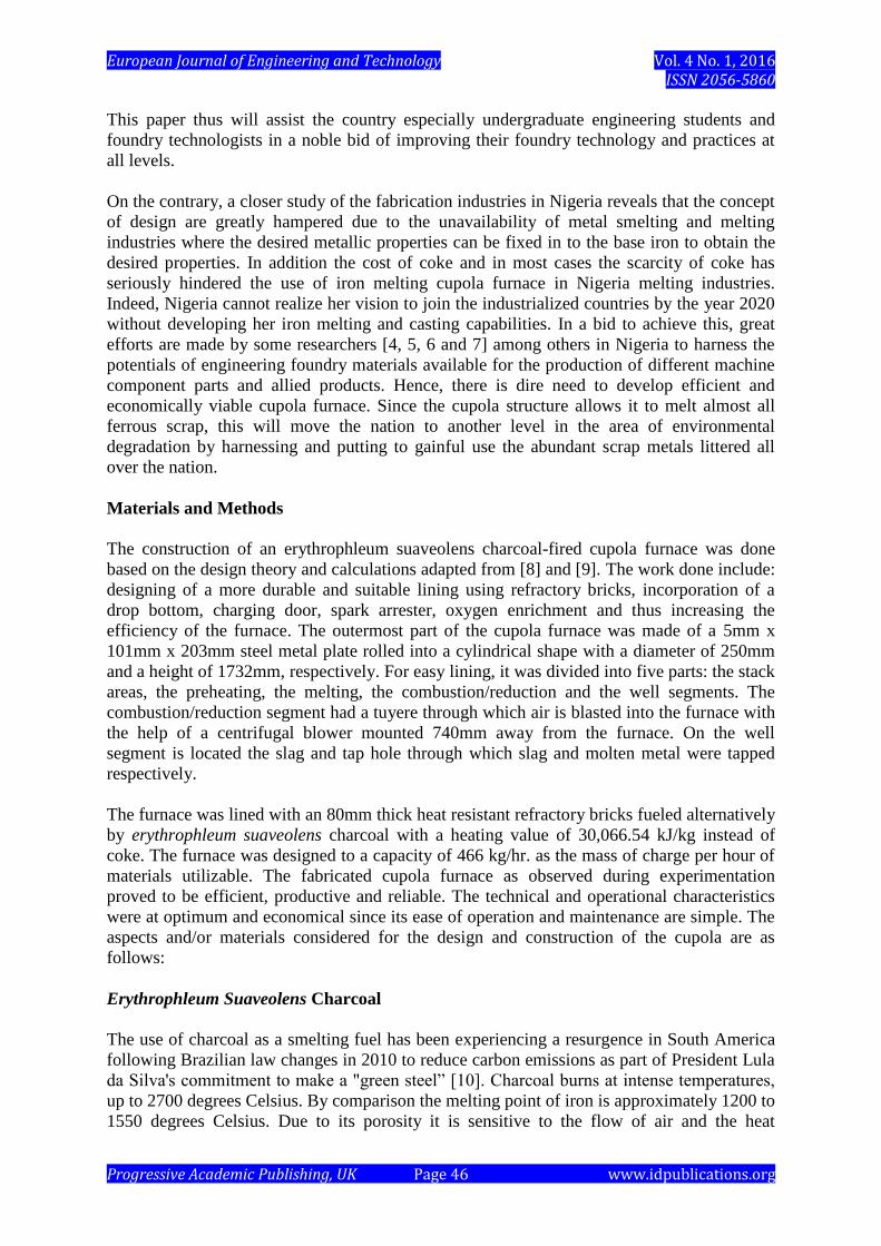
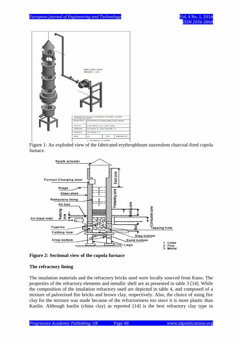
efficiency of the furnace. The outermost part of the cupola furnace was made of a 5mm x
101mm x 203mm steel metal plate rolled into a cylindrical shape with a diameter of 250mm
and a height of 1732mm, respectively. For easy lining, it was divided into five parts: the stack
areas, the preheating, the melting, the combustion/reduction and the well segments. The
combustion/reduction segment had a tuyere through which air is blasted into the furnace with
the help of a centrifugal blower mounted 740mm away from the furnace. On the well
segment is located the slag and tap hole through which slag and molten metal were tapped
respectively.
The furnace was lined with an 80mm thick heat resistant refractory bricks fueled alternatively
by erythrophleum suaveolens charcoal with a heating value of 30,066.54 kJ/kg instead of
coke. The furnace was designed to a capacity of 466 kg/hr. as the mass of charge per hour of
materials utilizable. The fabricated cupola furnace as observed during experimentation
proved to be efficient, productive and reliable. The technical and operational characteristics
were at optimum and economical since its ease of operation and maintenance are simple. The
aspects and/or materials considered for the design and construction of the cupola are as
follows:
Erythrophleum Suaveolens Charcoal
The use of charcoal as a smelting fuel has been experiencing a resurgence in South America
following Brazilian law changes in 2010 to reduce carbon emissions as part of President Lula
da Silva's commitment to make a "green steel” [10]. Charcoal burns at intense temperatures,
up to 2700 degrees Celsius. By comparison the melting point of iron is approximately 1200 to
1550 degrees Celsius. Due to its porosity it is sensitive to the flow of air and the heat
European Journal of Engineering and Technology Vol. 4 No. 1, 2016 ISSN 2056-5860
Progressive Academic Publishing, UK Page 47 www.idpublications.org
generated can be moderated by controlling the air flow to the fire. For this reason charcoal is
an ideal fuel for a forge and is still widely used by blacksmiths. Charcoal is also an excellent
reducing fuel for the production of iron and has been used that way since Roman times. In the
16th century England had to pass laws to prevent the country from becoming completely
denuded of trees due to production of iron. In the 19th century charcoal was largely replaced
by coke, baked coal, in steel making due to cost. Charcoal is far superior fuel to coke,
however, because it burns hotter and has no sulfur. Until World War II charcoal was still
being used in Sweden to make ultra high-quality steel. In steel-making, charcoal is not only a
fuel, but a source for the carbon in the steel [11]. Erythrophleum Suaveolens is the tree whose
charcoal was used in this research work. Erythrophleum suaveolens occurs in moist semi-
deciduous forests, gallery forest and wooded grasslands, from sea-level up to 1100 m altitude.
It is absent from the evergreen forest [12]. The characteristics of the erythrophleum
suaveolens charcoal used in this work are presented in tables 1 and 2.
Table 1: Results of proximate analysis of Okaba coal and Erythrophleum Suaveolens
charcoal S/NO Parameters % Okaba coal Erythrophleum Suaveolens charcoal
1 Moisture 9.4 0.94
2 Ash 11.6 6.13
3 Volatile matter 35.3 6.77
4
5
Fixed carbon
Sulphur (ad)
43.7
0.6
86.16
0.003
Source: [13]
Table 2: Results of ultimate analysis of Okaba coal and Erythrophleum Suaveolens
charcoal S/NO Parameters Okaba coal (daf) Erythrophleum Suaveolens charcoal (ad)
1 % C 71 77.5
2 % H 5.9 9
3 % O 21.2 5.48
4
5
6
7
% N
% Ash
sulphur
Calorific value raw
(Kcal./Kg)
1.9
11.6
0.6 (ad)
6192.8056
1.89
6.13
0.003 (ad)
7158.6995
Source: [13]
The furnace
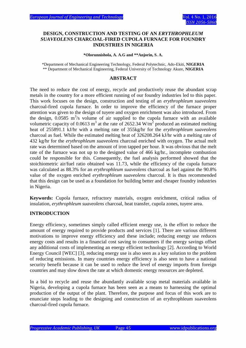
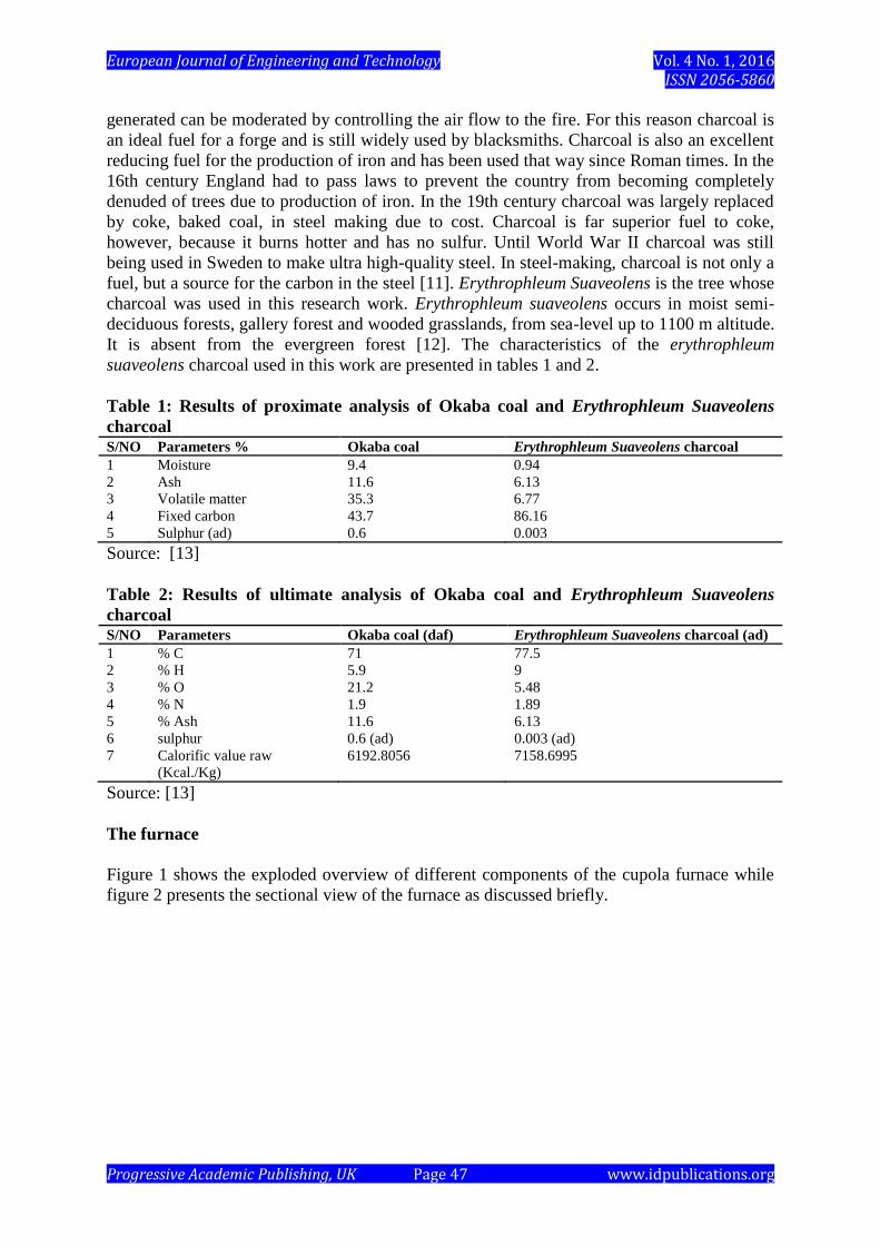
Figure 1 shows the exploded overview of different components of the cupola furnace while
figure 2 presents the sectional view of the furnace as discussed briefly.
European Journal of Engineering and Technology Vol. 4 No. 1, 2016 ISSN 2056-5860
Progressive Academic Publishing, UK Page 48 www.idpublications.org
Figure 1: An exploded view of the fabricated erythrophleum suaveolens charcoal-fired cupola
furnace.
Figure 2: Sectional view of the cupola furnace
The refractory lining
The insulation materials and the refractory bricks used were locally sourced from Kano. The
properties of the refractory elements and metallic shell are as presented in table 3 [14]. While
the composition of the insulation refractory used are depicted in table 4, and composed of a
mixture of pulverized fire bricks and brown clay, respectively. Also, the choice of using fire
clay for the mixture was made because of the refractoriness too since it is more plastic than
Kaolin. Although kaolin (china clay) as reported [14] is the best refractory clay type in

European Journal of Engineering and Technology Vol. 4 No. 1, 2016 ISSN 2056-5860
Progressive Academic Publishing, UK Page 49 www.idpublications.org
existence because it will not soften below 1750, they possess little plasticity due to their large
clay particles.
Table 3: Properties of refractory elements and metallic shell S/N Refractory element Length (m) Thermal conductivity (W/mK) Melting temperature (
oC)
1 Refractory brick (unshaped) 0.08 0.138 1870 (3400oF)
2 Binder (mortar) 0.005 0.48 -
3 Silicon carbide - - 1870 (3400 oF)
4
5
Limestone
Metal shell
-
0.03
-
45
2570 (4660 oF)
-
Table 4: Material contents of refractory lining S/N Material Thermal conductivity (W/mK) Temperature (
oC)
1 Refractory clay 1.035 450
2 Brown clay 0.221 20
Melting and Tapping temperature measurement
The melting and tapping temperature of the cupola was measured using the k-type
thermocouple and digital multimeter with the specifications presented in table 5. The melting
and tapping temperatures as measured during the experiment are presented in table 6.
Table 5: Digital Multimeter Specifications S/N Parameters Quantity/units
1 Max. voltage between terminals and earth ground 1000V dc or 750V rms ac (sine)
2 Power supply 9V NEDA 1604 6F22 006P
3 Ranging method Auto/Manual
4 Display LCD, 3999 counts max and bar graph consists of
38 segments
5 Operating temperature 5 oC to 35
oC
6 Storage temperature -10 oC to 60
oC
7 Dimension 78mm x 186mm x 35mm
8 Weight 300g (including battery)
Table 6: Melting zone and tapping temperatures Fuel type Melting zone temperature (oC) Tapping temperature (oC)
Erythrophleum suaveolens charcoal 1600 769
Erythrophleum suaveolens charcoal with oxygen
enrichment
1670 1074
DESIGN CONSIDERATIONS
According to Chastain [8] the following parameters were assumed:
i. Cupola diameter = 250 mm,
ii. ratio of metal to coke = 6:1
Cupola Height
The height of cupola is normally stated relative to its diameter. This ranges between 4D to 6D
and for a small cupola 5D is recommended [9]. Effective height of Cupola, H, is the distance
between the axis of the lower row of tuyeres and the charging door. Therefore, effective
height (H) of cupola using 5D as recommended by [9] is as shown in eqn. (1);
𝐻
𝐷= 5
…1
European Journal of Engineering and Technology Vol. 4 No. 1, 2016 ISSN 2056-5860
Progressive Academic Publishing, UK Page 50 www.idpublications.org
∴ 𝐻 = 5 × 250 = 1250 𝑚𝑚 where D = 250 mm.
Designs for Tuyere
This was designed in two steps; the area and the required number of tuyere.
Tuyere area
The tuyere area is based on the inside diameter of the cupola at the tuyere level. Standard
ratios for smaller cupolas range from 1/6 to 1/4 of cross sectional area of the cupola of the
tuyeres [8]. Tuyere area can be calculated as follows:
Using the ratio 1/6 the sectional area at tuyere level [8].
𝑡𝑢𝑦𝑒𝑟𝑒 𝑎𝑟𝑒𝑎, 𝐴𝑡 =1
6𝐴𝑐
…2
where;
Ac = Sectional area of cupola (m2) or Area of well
also;
𝐴𝑐 = 𝜋 (𝐷
2)
2
…3
= 3.14(2502⁄ )
2
= 49093.75 𝑚𝑚2 ≅ 0.049𝑚2
∴ 𝐴𝑡 =1
6𝐴𝑐 =
1
6× 0.049 = 0.00817 = 8170 𝑚𝑚2
Number of tuyere
Cupolas of 500 mm – 700 mm diameter have four tuyeres in each row [9]. The number of
tuyeres for the 250 mm diameter cupola is four. Therefore, the cross sectional area of the
combined four tuyere is 0.008m2 (8000mm
2).
The cross sectional area of each of the four tuyeres is
8170
4= 2042.5 𝑚𝑚2𝑜𝑟 0.0020425 𝑚2
also;
𝜋 (𝐷𝑡
2)
2
= 2042.5
∴ 𝐷𝑡 = √2042.5 × 4
3.142= 50.993 𝑚𝑚 ≅ 51 𝑚𝑚
i.e. tuyere diameter = 51 mm
Now to find a suitable diameter pipe;
𝐴𝑟𝑒𝑎 𝑜𝑓 𝑝𝑖𝑝𝑒, 𝐴𝑝 = 𝜋(𝐷𝑝
2)2
…4
where;
Dp = Pipe diameter
also;
𝑁𝑢𝑚𝑏𝑒𝑟 𝑜𝑓 𝑡𝑢𝑦𝑒𝑟𝑒𝑠 =𝐴𝑡
𝐴𝑝
…5

European Journal of Engineering and Technology Vol. 4 No. 1, 2016 ISSN 2056-5860
Progressive Academic Publishing, UK Page 51 www.idpublications.org
∴ 𝐴𝑝 =𝐴𝑡
4=
8170
4= 2042.5 𝑚𝑚2
∴ 𝐷𝑝 = √𝐴𝑝×4
𝜋= √
2042.5 × 4
3.142= 50.993 𝑚𝑚 ≅ 51 𝑚𝑚
Therefore, a 51 mm (≈2-inch) pipe is required.
Designs for Notch
Height of the slag notch and the available furnace volume
The height of the slag notch (HS) to base of the heart ranges from (0.7 to 1.1) D and for a
small cupola 0.7 D is recommended by [9].
Therefore, height of slag notch using 0.7D was given by [9] as shown in eqn. (6);
𝐻𝑠 = 0.7𝐷 …6
∴ 𝐻𝑠 = 0.7 × 250 = 175 𝑚𝑚 also;
the available furnace volume, Vf = (𝐴𝑐 × 𝐻𝑒) [8]
…7
where;
𝐻𝑒 = effective cupola height
𝐴𝑐 = Area of cupola = 0.049 m2 and
∴ 𝑉𝑓 = 1.25 × 0.049 = 0.06125 𝑚3 ≅ 0.0613 𝑚3
Size of iron notch
The size of iron notch up to 5 tons /hr is 15 mm in diameter [9]. Therefore, the size of iron
notch for this cupola will be taken as 15mm.
The size of slag notch
The size of slag notch up to 5ton /hr is 30 – 50mm in diameter and for a small cupola of 356
kg/hr, 30 mm is recommended [9]. Therefore, the size of slag notch for this cupola furnace
will be taken as 30 mm in diameter
Height of tuyere
Height of tuyere, Ht, from bottom plate includes the (height of the 50.8mm sand bottom) +
(175 mm height of the slag hole) + (127 mm constant) [8].
𝐻𝑡 = 50.8 + 175 + 127 = 352.8 mm
Cupola Leg Height
Minimum leg height is given as follows;
𝐻𝑚 = 𝐿𝑑 + 𝑎 + 𝑑𝑠 [8]
…8
Calculating the minimum leg height, the following parameters were assumed according to
Chastain (2000);
𝐿𝑑 = 𝑙𝑒𝑛𝑔𝑡ℎ 𝑜𝑓 𝑑𝑜𝑜𝑟 = 135 𝑚𝑚
𝑎 = 𝑐𝑜𝑛𝑠𝑡𝑎𝑛𝑡 = 152.4 𝑚𝑚

European Journal of Engineering and Technology Vol. 4 No. 1, 2016 ISSN 2056-5860
Progressive Academic Publishing, UK Page 52 www.idpublications.org
𝑑𝑠 = 𝑑𝑒𝑝𝑡ℎ 𝑜𝑓 𝑠𝑎𝑛𝑑 𝑏𝑒𝑑 𝑐𝑜𝑣𝑒𝑟𝑖𝑛𝑔 𝑡ℎ𝑒 𝑓𝑜𝑢𝑛𝑑𝑎𝑡𝑖𝑜𝑛 = 50.8 𝑚𝑚
∴ 𝐻𝑚 = 135 + 152.4 + 50.8 = 338.2 𝑚𝑚
Where: 𝐻𝑚 = 𝑚𝑖𝑛𝑖𝑚𝑢𝑚 𝑙𝑒𝑔 ℎ𝑒𝑖𝑔ℎ𝑡 𝑜𝑓 𝑐𝑢𝑝𝑜𝑙𝑎
Leg height may be adjusted upward from this figure to increase operator comfort.
Area of Wind Belt
The area of wind belt ranges between 1.3 At to 1.6 At [8]. Therefore, using 1.6 At as
recommended by [8], the equation will appear as shown in eqn. (9)
𝐴𝑤 = 1.6 At …9
1.6 × 8170 = 13072 𝑚𝑚2 But the cross sectional area of wind belt is
1.6 × 𝜋 (𝐷
2)
2
= 13072 𝑚𝑚2
∴ 𝐷 = √13072 × 4
3.142 × 1.6
= 101.985 𝑚𝑚 ≅ 102 mm =diameter of wind belt
Bed Height
Actual bed height depends upon the operation of the cupola. For large cupolas the height
given by [8] is modified as shown below;
𝐻𝑏=152.4 + 52.917√𝑃𝑏
1.73
…10
where;
𝐻𝑏=𝑏𝑒𝑑 ℎ𝑒𝑖𝑔ℎ𝑡 𝑃𝑏 = 𝑏𝑙𝑎𝑠𝑡 𝑝𝑟𝑒𝑠𝑠𝑢𝑟𝑒 where;
𝐻𝑏=𝑏𝑒𝑑 ℎ𝑒𝑖𝑔ℎ𝑡 (m)
𝑃𝑏 = 𝑏𝑙𝑎𝑠𝑡 𝑝𝑟𝑒𝑠𝑠𝑢𝑟𝑒 The constant of 152.4 mm is added to minimum height and represents the maximum height of
the bed this will usually give hotter iron. Calculating the minimum height of the bed for the
250 mm diameter cupola, 127mm blast pressure is recommended [8]. Therefore;
𝐻𝑏=52.917√127
1.73 = 453.39 mm
also,
Maximum bed height = 152.4 + 453.39 = 605.79 mm
Charge Weights
The weight of fuel, Wf, used per charge given by [8] is modified as;
𝑊𝑓 = 55.294𝐴𝑐
…11
Where; 𝐴𝑐 = 0.049 𝑚2
∴ 𝑊𝑓 = 55.294 × 0.049 = 2.709 𝐾𝑔 ≅ 3𝐾𝑔
The weight of iron (metal) charges is proportional to the weight of the fuel charges. Common
ratios are from 6:1 to 10:1.
European Journal of Engineering and Technology Vol. 4 No. 1, 2016 ISSN 2056-5860
Progressive Academic Publishing, UK Page 53 www.idpublications.org
Therefore, weight of iron at 6:1 ratio is
6 × 2.765 = 16.59 𝑘𝑔 ≅ 17 𝐾𝑔
The mass of charge of material
The mass of charge of material is given by [8] as;
𝑀𝑐𝑚 = 𝜌𝑟 . 𝑉𝑓
…12
where:
𝜌𝑟 = 𝑑𝑒𝑛𝑠𝑖𝑡𝑦 𝑜𝑓 𝑖𝑟𝑜𝑛 = 7.6 𝑔/𝑐𝑚3 = 7600𝑘𝑔/𝑚3
𝑉𝑓 = 𝑎𝑣𝑎𝑖𝑙𝑎𝑏𝑙𝑒 𝑓𝑢𝑟𝑛𝑎𝑐𝑒 𝑣𝑜𝑙𝑢𝑚𝑒 = 0.0613 𝑚3
∴ 𝑀𝑐𝑚 = 7600 × 0.0613 = 465.88 𝐾𝑔 ≈ 466𝐾𝑔 = 𝑚𝑒𝑙𝑡 𝑟𝑎𝑡𝑒 𝑜𝑓 466𝑘𝑔/ℎ𝑟. also;
𝑒𝑓𝑓𝑒𝑐𝑡𝑖𝑣𝑒 ℎ𝑒𝑖𝑔ℎ𝑡 𝑜𝑓 𝑤𝑒𝑙𝑙, 𝐻𝑤 =𝑉𝑤
𝐴𝑐 [8]
…13
where:
volume of well, Vw = (𝐻𝑠 × 𝐴𝑐) = 0.175 × 0.049 = 0.0086𝑚3 [8]
…14
𝐻𝑤 = 𝑒𝑓𝑓𝑒𝑐𝑡𝑖𝑣𝑒 ℎ𝑒𝑖𝑔ℎ𝑡 𝑜𝑓 𝑤𝑒𝑙𝑙
𝐻𝑤 =8600 𝑐𝑚3
490 𝑐𝑚2= 17.55 𝑐𝑚 0𝑟 175.5 𝑚𝑚
The required air flow rate for cupola
According to [8], best cupola operation occurs with incomplete combustion and that stack
gases should contain 13% CO2, 13.2% CO and 73.8% N. The CO burns to CO2 as it is
discharged from the stack, giving a large visible flame if melting at night. The amount of air
required to melt kilograms of iron per hour can be calculated. 0.454 kg of carbon requires
3.1998 m3 of air to produce the 13% CO2- 13.2% CO ratio. Charcoal contains approximately
90% carbon [8]. Therefore, an air requirement for cupola was given by [8] as shown in eqn.
(15);
𝑀𝑐𝑚 ×𝑞𝑐
𝑞𝑚×
𝑞𝑐𝑎
𝑞𝑐× 1hr. = 𝑞�̇�
…15
466 ×1
6×
0.9
1×
1 ℎ𝑜𝑢𝑟
60 𝑚𝑖𝑛.= 1.165 𝑘𝑔 𝑚𝑖𝑛.⁄
also; 𝑞𝑎
𝑞𝑐𝑎× 𝑞�̇� = 𝑟𝑒𝑞𝑢𝑖𝑟𝑒𝑑 𝑎𝑖𝑟 𝑓𝑙𝑜𝑤 𝑟𝑎𝑡𝑒 𝑓𝑜𝑟 𝑐𝑢𝑝𝑜𝑙𝑎 [8]
…16 3.1998
0.454 × 1.165 = 8.21𝑚3/𝑚𝑖𝑛
where; 𝑞𝑐
𝑞𝑚= ratio of charcoal to metal,
𝑞𝑐𝑎
𝑞𝑐 = ratio of carbon to charcoal,
𝑞�̇� = quantity of charcoal required per minute, 𝑞𝑎
𝑞𝑐𝑎 = ratio of air to carbon.
The shop blower rating to be used on cupola will depend on the required cubic meter of air
per minute (m3/min.)
European Journal of Engineering and Technology Vol. 4 No. 1, 2016 ISSN 2056-5860
Progressive Academic Publishing, UK Page 54 www.idpublications.org
Selection of Cupola Blowers
The recommended blower size (Z) by [8] is modified as;
.min/1113
mAC
…17
∴ 𝑍 = 111 × 0.049 = 5.43 𝑚3/𝑚𝑖𝑛. where AC
= 0.049 m2
Blowers are frequently sized up 10% to make up for leaks in the system and variations in
temperature. However, they are often run at 80% to 90% of the calculated value. Therefore,
the 10 % sized up value is 5. 974 𝑚3/𝑚𝑖𝑛. ≈ 6𝑚3/𝑚𝑖𝑛. i.e. the recommended blower size
for this cupola. Recommended blower sizes for a range of cupola are shown in Table 7 [8].
Table 7: Blower sizes for cupola operation Inside
Diameter
in (inches)
Area
(inches2)
Actual
cfm
recommended
Blower size
(cfm) m3/min.
Discharge
pressure
Oz
10 78.5 165 216 6.12 8
18 254 510 700 19.82 16
23 415 830 1140 32.28 20
For this design, an electrically powered centrifugal blower was selected over axial, due to its
obvious advantages [15]. The specifications of the blower are given as in table 8.
Table 8: Blower specifications S/N Parameters Quantity/units
1 Number of blades 6
2 Rated speed 2800
3 Rated voltage 220V
4 Volume flow rate 8.5 m3/min.
5 Diameter of discharge pipe 74mm (0.074m)
6 Rated current 250A
Oxygen Enrichment
Oxygen enrichment of the blast air is used for two main reasons; to increase the melt rate, or
to increase the temperature of the tap. Other reasons for oxygen enrichment would include
reduction of coke and the reduction of sulfur in the tap. If a cupola is producing its maximum
output, the output may be further increased by as much as 25% with the addition of oxygen to
the blast air as shown in Table 9 [8].
Table 9: Increase in melt rate relative to the percent higher oxygen levels. Oxygen Increase in melt rate
1% 8%
2% 15%
3% 21%
4% 25%
While the reduction of the blast is dependent upon the percent of oxygen introduced and is
summarized in the Table 10 [8].
European Journal of Engineering and Technology Vol. 4 No. 1, 2016 ISSN 2056-5860
Progressive Academic Publishing, UK Page 55 www.idpublications.org
Table 10: Reduction of the blast relative to the percent of oxygen introduced. Oxygen Blast reduction
1% 6%
2% 11%
3% 16%
4% 20%
Calculating the volume flow rate (m3/min.) of oxygen for a 5.43 𝑚3/𝑚𝑖𝑛 blast (actual blast)
using 4 % oxygen enrichment [8];
𝑉�̇� = 𝑍 × % 𝑜𝑥𝑦𝑔𝑒𝑛 𝑒𝑛𝑟𝑖𝑐ℎ𝑚𝑒𝑛𝑡 …18
𝑉�̇� = 5.43 × 4100⁄ = 0.217 𝑚3/𝑚𝑖𝑛
The equation for calculating the new reduced blast air flow rate for a percentage increase in
oxygen for a actual blast of 5.43 𝑚3/𝑚𝑖𝑛 was given by [8] as shown in eqn. (19);
𝑍𝑟 = [𝑍– (𝑍 × % 𝑜𝑥𝑦𝑔𝑒𝑛 𝑟𝑒𝑑𝑢𝑐𝑡𝑖𝑜𝑛)] …19
𝑍𝑟 = [5.43 – (5.43 × 20100⁄ )] = 4.344 𝑚3/𝑚𝑖𝑛
where;
𝑉�̇� = required oxygen flow rate
𝑍𝑟 = new reduced blast air flow rate
Volume of air supplied
A shop made manometer was used to take the air pressure measurement. The pitot tubes
connected to the manometer was inserted through a hole in the side of the duct and pointed
squarely into the airflow. The air pressure readings were taken with the manometer and the
velocity and volume of airflow can therefore be calculated from the manometer reading as
follows:
Velocity of airflow given by [8] is modified as;
𝑉 = 7658√h …20
Where;
𝑉 = 𝑣𝑒𝑙𝑜𝑐𝑖𝑡𝑦 𝑖𝑛 𝑚/𝑚𝑖𝑛. ℎ = ℎ𝑒𝑖𝑔ℎ𝑡 𝑖𝑛 𝑚𝑒𝑡𝑒𝑟 𝑤𝑎𝑡𝑒𝑟 𝑐𝑜𝑙𝑢𝑚𝑛 = 0.045𝑚 = 4.5 𝑐𝑚
∴ 𝑉 = 7658√0.045 = 1624.50709 𝑚/𝑚𝑖𝑛. Volume flow rate of airflow is calculated by:
𝑉𝑎 = 𝐴𝑚𝑉 [8]
…21
where;
𝐴𝑚 = 𝑎𝑟𝑒𝑎 𝑜𝑓𝑏𝑙𝑎𝑠𝑡 𝑚𝑎𝑖𝑛 𝑖𝑛 𝑚2 Calculating the volume of airflow for 250 mm cupola with a 51 mm diameter blast main:
Actual inside diameter of blast main, Dp = 51 mm
Area of blast main in square feet given by [8] is modified as;
Area of blast main (𝐴𝑚) in square meter = 3. 325 (𝐷𝑝
2⁄ )
2
…22
∴ 𝐴𝑚 = 3.325(0.0512⁄ )
2
= 0.00216 𝑚2
𝑉𝑎 = 0.00216 × 1624.50709 = 3.5089 𝑚3/𝑚𝑖𝑛. = 0.0585 𝑚3/𝑠
European Journal of Engineering and Technology Vol. 4 No. 1, 2016 ISSN 2056-5860
Progressive Academic Publishing, UK Page 56 www.idpublications.org
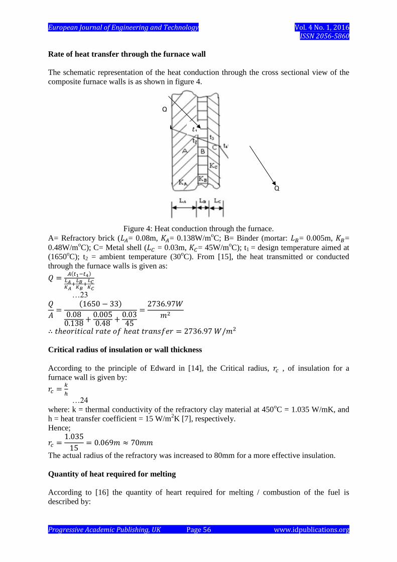
Rate of heat transfer through the furnace wall
The schematic representation of the heat conduction through the cross sectional view of the
composite furnace walls is as shown in figure 4.
Figure 4: Heat conduction through the furnace.
A= Refractory brick (𝐿𝐴= 0.08m, 𝐾𝐴= 0.138W/moC; B= Binder (mortar: 𝐿𝐵= 0.005m, 𝐾𝐵=
0.48W/moC); C= Metal shell (𝐿𝐶 = 0.03m, 𝐾𝐶= 45W/m
oC); t1 = design temperature aimed at
(1650oC); t2 = ambient temperature (30
oC). From [15], the heat transmitted or conducted
through the furnace walls is given as:
𝑄 =𝐴(𝑡1−𝑡4)
𝐿𝐴𝐾𝐴
+𝐿𝐵𝐾𝐵
+𝐿𝐶𝐾𝐶
…23 𝑄
𝐴=
(1650 − 33)
0.080.138 +
0.0050.48 +
0.0345
=2736.97𝑊
𝑚2
∴ 𝑡ℎ𝑒𝑜𝑟𝑖𝑡𝑖𝑐𝑎𝑙 𝑟𝑎𝑡𝑒 𝑜𝑓 ℎ𝑒𝑎𝑡 𝑡𝑟𝑎𝑛𝑠𝑓𝑒𝑟 = 2736.97 𝑊/𝑚2
Critical radius of insulation or wall thickness
According to the principle of Edward in [14], the Critical radius, 𝑟𝑐 , of insulation for a
furnace wall is given by:
𝑟𝑐 =𝑘
ℎ
…24
where: k = thermal conductivity of the refractory clay material at 450oC = 1.035 W/mK, and
h = heat transfer coefficient = 15 W/m2K [7], respectively.
Hence;
𝑟𝑐 =1.035
15= 0.069𝑚 ≈ 70𝑚𝑚
The actual radius of the refractory was increased to 80mm for a more effective insulation.
Quantity of heat required for melting
According to [16] the quantity of heart required for melting / combustion of the fuel is
described by:
Q
𝑡1
Q
European Journal of Engineering and Technology Vol. 4 No. 1, 2016 ISSN 2056-5860
Progressive Academic Publishing, UK Page 57 www.idpublications.org
𝑄𝑚 = 𝐶𝑚 × 𝑇𝑚 × 𝐺𝑚 …25
where: 𝐶𝑚 = specic heat capacity of cast iron = 0.46 kJ/kgK;
𝑇𝑚 = 𝑡𝑒𝑚𝑝𝑒𝑟𝑎𝑡𝑢𝑟𝑒 𝑑𝑖𝑓𝑓𝑒𝑟𝑒𝑛𝑐𝑒, (𝑇2 − 𝑇1) = 1650𝑜𝐶 − 33𝑜𝐶
𝑎𝑛𝑑 𝐺𝑚 = 𝑐𝑢𝑝𝑜𝑙𝑎 𝑓𝑢𝑟𝑛𝑎𝑐𝑒 𝑐𝑎𝑝𝑎𝑐𝑖𝑡𝑦 𝑜𝑟 𝑚𝑒𝑙𝑡 𝑟𝑎𝑡𝑒 = 466𝑘𝑔/ℎ𝑟 (Designed value)
Hence, the quantity of heat required for melting is calculated as:
𝑄𝑚 = 0.46 × (1650 − 33) × 466 = 346620.12kJ/hr (Theoretical)
Efficiency / Output of the cupola
According to [4] the efficiency of the cupola is given by:
𝐸𝑓𝑓𝑖𝑐𝑖𝑒𝑛𝑐𝑦
=𝑄𝑢𝑎𝑛𝑡𝑖𝑡𝑦 𝑜𝑓ℎ𝑒𝑎𝑡 𝑟𝑒𝑞𝑢𝑖𝑟𝑒𝑑𝑓𝑜𝑟 𝑚𝑒𝑙𝑡𝑖𝑛𝑔 − 𝑐𝑎𝑙𝑜𝑟𝑖𝑓𝑖𝑐 𝑣𝑎𝑙𝑢𝑒 𝑜𝑓 𝑡ℎ𝑒 𝑓𝑢𝑒𝑙 ×
𝑄𝑢𝑎𝑛𝑡𝑖𝑡𝑦 𝑜𝑓ℎ𝑒𝑎𝑡 𝑟𝑒𝑞𝑢𝑖𝑟𝑒𝑑𝑓𝑜𝑟 𝑚𝑒𝑙𝑡𝑖𝑛𝑔100
Mathematically,
𝜀 =𝑄𝑚−Cvf
𝑄𝑚× 100
…26
∴ 𝜀 =346620.12 − 30066.54
346620.12× 100 = 91.3%
Where: calorific value of Erythrophleum Suaveolens charcoal, Cvf is 30066.54kJ/kg
91.3% is the expected or theoretical efficiency of the cupola furnace.
Fuel analysis
The stoichiometric air/fuel ratio is calculated thus:
Let the equivalent formula for the E. S charcoal sample = CiHjOkNlSm
Then, the combustion equation for the E.S charcoal is written as:
CiHjOkNlSm + xO2 + x79
21N2 → pCO2 + qH2O + rSO2 + sN2
…27
where;
C = 77.5 %; H = 9%; O = 5.48 %; N = 1.89 %; S = 0.003 %; C: 12i = 77.5; i = 6.46; H: 1j= 9; j = 9
O: 16k = 5.48; k = 0.343; N: 14l = 1.89; l = 0.135; S: 32m = 0.003; m = 0.00009 Hence, the combustion equation becomes;
C6.46H9O0.343N0.135S0.00009 + xO2 + x79
21N2 → pCO2 + qH2O + rSO2 + sN2
Balancing the equation yields:
C: 6.46 = p; p = 6.46
H: 9 = 2q; q = 4.5
S: 0.00009 = r; r = 0.00009
O: 0.343 + 2x = 2p + q + 2r = 2(6.46) + 4.5 + 2(0.00009)
0.343 + 2x = 17.42018
x = 8.54
N: 0.135 + 2 ×79
21x = 2s = 0.135 + 2(3.762)8.54
2s = 64.38996
𝑠 = 32.195 Hence, the balanced combustion equation becomes;
European Journal of Engineering and Technology Vol. 4 No. 1, 2016 ISSN 2056-5860
Progressive Academic Publishing, UK Page 58 www.idpublications.org
C6.46H9O0.343N0.135S0.00009 + 8.54O2 + 8.5479
21N2
→ 6.46CO2 + 4.5H2O + 0.00009SO2 + 32.195N2
Thus, the stoichiometric air/fuel ratio required = 8.54(32)+8.54(
79
21)28
100= 11.73
Actual rate of heat transfer through the furnace wall
Actual rate of heat transferred through the furnace wall is calculated as follows: 𝑄
𝐴=
(1600 − 33)
0.080.138 +
0.0050.48 +
0.0345
=2652.34𝑊
𝑚2
∴ 𝑎𝑐𝑡𝑢𝑎𝑙 𝑟𝑎𝑡𝑒 𝑜𝑓 ℎ𝑒𝑎𝑡 𝑡𝑟𝑎𝑛𝑠𝑓𝑒𝑟 = 2652.34 𝑊/𝑚2
Actual quantity of heat used for melting with E.S charcoal as fuel
Using equation 25; where: 𝐶𝑚 = specic heat capacity of cast iron = 0.46 kJ/kgK;
𝑇𝑚 = 𝑡𝑒𝑚𝑝𝑒𝑟𝑎𝑡𝑢𝑟𝑒 𝑑𝑖𝑓𝑓𝑒𝑟𝑒𝑛𝑐𝑒, (𝑇2 − 𝑇1) = 1600𝑜𝐶 − 33𝑜𝐶
𝑎𝑛𝑑 𝐺𝑎𝑚 = 𝑎𝑐𝑡𝑢𝑎𝑙 𝑚𝑒𝑙𝑡 𝑟𝑎𝑡𝑒 = 355𝑘𝑔/ℎ𝑟 Hence, the actual quantity of heat used for melting with E.s charcoal as fuel is calculated as:
𝑄𝑚 = 0.46 × (1600 − 33) × 355 = 255891.1kJ/ℎ𝑟
Actual efficiency / Output of the cupola with E.S charcoal as fuel
Using equation 26;
𝜀 =255891.1 − 30066.54
255891.1× 100 = 88.3%
88.3% is the actual efficiency of the cupola furnace.
Quantity of heat used for melting with combined E.S charcoal and oxygen enrichment
as fuel
Using equation 25; where: 𝐶𝑚 = specic heat capacity of cast iron = 0.46 kJ/kgK;
𝑇𝑚 = 𝑡𝑒𝑚𝑝𝑒𝑟𝑎𝑡𝑢𝑟𝑒 𝑑𝑖𝑓𝑓𝑒𝑟𝑒𝑛𝑐𝑒, (𝑇2 − 𝑇1) = 1670𝑜𝐶 − 33𝑜𝐶
𝑎𝑛𝑑 𝐺𝑎𝑚 = 𝑎𝑐𝑡𝑢𝑎𝑙 𝑚𝑒𝑙𝑡 𝑟𝑎𝑡𝑒 = 433.2𝑘𝑔/ℎ𝑟 Hence, the actual quantity of heat used for melting with E.s charcoal as fuel is calculated as:
𝑄𝑚 = 0.46 × (1670 − 33) × 433.2 = 326208.264kJ/hr
Efficiency / Output of the cupola with combined E.S charcoal and oxygen enrichment as
fuel
Using equation 26;
𝜀 =326208.264 − 30066.54
326208.264× 100 = 90.8%
90.8% is the actual efficiency of the cupola furnace.
CONCLUSION AND RECOMMENDATIONS
Conclusion
An Erythrophleum suaveolens charcoal-fired cupola furnace has been developed. The
produced cupola could further assist manufacturers who wish to build larger furnaces for
European Journal of Engineering and Technology Vol. 4 No. 1, 2016 ISSN 2056-5860
Progressive Academic Publishing, UK Page 59 www.idpublications.org
commercial application with reduced cost implication. Furthermore, the fabricated cupola as
modified during test running proved to be more economical having the optimum technical
and operational characteristics with the capability of accepting a wide range of materials
without reducing melts quality. This furnace will therefore play an important role in the metal
recycling industry because of its inherent qualities such as productivity, efficiency, reliability,
simplicity, ease of operation and maintainability.
Recommendations
From the study conducted, these recommendations were proffered:
That the design should be adopted by foundry technologists
The foundry industries should embrace this design as a basis for further improvement
and cost reduction in iron melting processes.
Acknowledgements
The authors acknowledge the National Metallurgical Development Centre, Jos, Federal
Polytechnic, Bauchi and The Federal Polytechnic Ado-Ekiti for allowing the use of their
workshops at various stages of this work.
REFERENCES
1. Diesendorf, M. (2007). Greenhouse solutions with sustainable energy. UNSW Press,
pp.86.
2. Anonymous (2008). The twin pillars of sustainable energy: synergies between energy
efficiency and renewable energy technology and policy. Aceee.org. Retrieved May 05
, 2008; from:http://web.arhive.org/web/ 3. World Energy Council (2012). Energy efficiency policies around the world: Review a
nd Evaluation. Accessed from: http://www.worldenergy.org/
4. Offor, P.O; Daniel, C.C. and Obikwelu, D.O.N (2010). Effects of Various Quenching
Media on the Mechanical Properties of Intercritically Annealed 0.15 wt% C {0.43
wt% Mn Steel. Nigerian Journal of Technology,Vol.29, No.2, pp.76-81.
5. Offor, P.O; Daniel, C.C. and Okorie, B.A (2011). The Effects of Intercritical Heat
Treatments on the Mechanical Properties of 0.14 wt% C { 0.56 wt% Mn { 0.13 wt%
Si Structural Steel. Nigerian Journal of Technology, Vol.30, No.3, pp.29-34.
6. The Engineering ToolBox. Solids-Specific Heats. A Comprehensive List of Some
Common Solids as Brick, Cement, Glass and Many More and their Speci_c Heats-
Imperial and SI Units, www.engineeringtoolbox.com/specific-heat-solids-d_154.html.
7. Ugwu ,H.U. and Ogbonnaya, E.A. (2013). Design and testing of a cupola furnace for
Michael
Okpara University of Agriculture, Umudike. Nigerian Journal of Technology
(NIJOTECH) Vol.32, No.1, pp.22-29.
8. Chastain, D.S. (2000). Iron melting cupola furnaces for the small foundry.
Jacksonville, FL; USA.
9. Lipnitsky, A. (1978). Melting of cast iron and non-ferrous alloys. Peace Publisher,
Moscow, pp.56
10. Kato1, M.; DeMarini D. M.; Carvalho, A. B.; Rego, M. A. V.; Andrade1, A. V.;
Bonfim, A.S.V. and Loomis D. (2012). World at work: Charcoal producing industries
in north eastern Brazil. Retrieved 16 September 2012; from:
http://oem.bmj.com/content.

European Journal of Engineering and Technology Vol. 4 No. 1, 2016 ISSN 2056-5860
Progressive Academic Publishing, UK Page 60 www.idpublications.org
11. Wikipedia, the free encyclopedia (2012). Charcoal. Retrieved 20 December 2012; fro
m: http://www.woodgas.com/biomass.htm
12. Okeyo, J.M., (2006). Erythrophleum suaveolens (Guill. & Perr.) Brenan. In:
Schmelzer, G.H. & Gurib-Fakim, A. (Editors). Prota 11(1): Medicinal plants/Plantes
médicinales 1. [CD- Rom]. PROTA, Wageningen, Netherlands.
13. Olorunnishola, A.A.G and Akintunde, M.A, (Dec. 2013). Characterizing Erythrophle
um Suaveolens Charcoal as a Viable Alternative Fuel to Coke in Iron Melting In
Nigeria. IOSR Journal of Mechanical and Civil Engineering (IOSR-JMCE), e-ISSN:
2278-1684,p-ISSN: 2320-334X, Volume 10, Issue 3 (Nov. - Dec. 2013), PP 06-11.
14. Ugwu, H. U. and Ojobor, S. N. (2011). Design and Fabrication of Thermal
Conductivity Measuring Equipment. International Review of Mechanical
Engineering, Vol. 5, Number 1, pp.134-142.
15. Rajput, R. K. (2007). Heat and Mass Transfer in S.I. Units. S. Chand & Company Ltd,
First Multi colour Illustrative Revised Edition, Ram Nagar, New Delhi, India.
16. Krivandin, V. A. (1980). Metallurgical Furnaces. Imported Publishers, Ltd, Hardcover
Edition: ISBN0828518300, Canada.