Embed Size (px)
Citation preview

Design Criteria Document for the
Hybrid Spectrometer (HYSPEC)
SNS SING14B-00-DC0001-R00 Date: 15 August 2005
August 2005

This report was prepared as an account of work sponsored by an agency of the United States government. Neither the United States government nor any agency thereof, nor any of their employees, makes any warranty, express or implied, or assumes any legal liability or responsibility for the accuracy, completeness, or usefulness of any information, apparatus, product, or process disclosed, or represents that its use would not infringe privately owned rights. Reference herein to any specific commercial product, process, or service by trade name, trademark, manufacturer, or otherwise, does not necessarily constitute or imply its endorsement, recommendation, or favoring by the United States government or any agency thereof. The views and opinions of authors expressed herein do not necessarily state or reflect those of the United States government or any agency thereof.

SING14B-00-DC0001-R00
DESIGN CRITERIA DOCUMENT FOR THE HYBRID SPECTROMETER
(HYSPEC)
M. E. Hagen and
W. J. Leonhardt
Date Published: August 2005
Prepared by OAK RIDGE NATIONAL LABORATORY
P.O. Box 2008 Oak Ridge, Tennessee 37831-6285
managed by UT-Battelle, LLC
for the U.S. DEPARTMENT OF ENERGY
Office of Science Basic Energy Science
under contract DE-AC05-00OR22725
DESIGN CRITERIA DOCUMENT FOR THE
HYBRID SPECTROMETER (HYSPEC)
August 2005
Mark Hagen Instrument Scientist, HYSPEC
Date
William J. Leonhardt Instrument Engineer, HYSPEC
Date
John Haines SING MIE Project Manager
Date

iii
TABLE OF CONTENTS
Page
LIST OF FIGURES ................................................................................................................................v
LIST OF TABLES.................................................................................................................................vi
ACRONYMS....................................................................................................................................... vii
1. INTRODUCTION............................................................................................................................1
2. SYSTEM REQUIREMENTS AND DESCRIPTION......................................................................4 2.1 DETECTORS .........................................................................................................................4
2.1.1 Linear Position-Sensitive Detectors............................................................................4 2.1.2 LPSD Mounting Frame...............................................................................................4 2.1.3 Neutron Beam Monitors..............................................................................................4 2.1.4 LPSD 8-Pack Modules................................................................................................5
2.2 OPTICAL COMPONENTS ...................................................................................................5 2.2.1 Core Vessel Insert .......................................................................................................5 2.2.2 Shutter Insert/Guide ....................................................................................................5 2.2.3 Beam Line Guide ........................................................................................................5 2.2.4 Focusing Crystals......................................................................................................10 2.2.5 Translation Mechanism for the Focusing Crystal Arrays .........................................12 2.2.6 Radial Collimator ......................................................................................................12 2.2.7 Wide Angle Supermirror Polarization Analyzer.......................................................13
2.3 CHOPPERS..........................................................................................................................14 2.3.1 T0 Chopper ...............................................................................................................14 2.3.2 T1A Frame Overlap Disk Chopper ...........................................................................14 2.3.3 T1B Order Suppression Disk Chopper .....................................................................15 2.3.4 T2 Straight (Short) Slotted Fermi Chopper...............................................................15
2.4 SAMPLE ENVIRONMENT ................................................................................................19 2.4.1 Sample Stage and Goniometer ..................................................................................19 2.4.2 X-Rail Components...................................................................................................19
2.5 SHIELDING.........................................................................................................................21 2.5.1 Beam Line Shielding.................................................................................................21 2.5.2 Drum Shield Housing for Focusing Crystals ............................................................22 2.5.3 Drum Shield Shutter..................................................................................................22 2.5.4 Detector Vessel Shielding .........................................................................................23 2.5.5 Beam Stop .................................................................................................................23
2.6 DATA ACQUISITION ........................................................................................................23 2.7 INSTRUMENT-SPECIFIC SUPPORT EQUIPMENT........................................................24
2.7.1 Drum Shield to Sample Stage Support Arm .............................................................24 2.7.2 Detector Vessel .........................................................................................................25 2.7.3 Motor Drive System..................................................................................................26 2.7.4 Instrument Control Computer ...................................................................................26 2.7.5 Control Cabin............................................................................................................26 2.7.6 Furniture....................................................................................................................26
2.8 INSTRUMENT INFRASTRUCTURE ................................................................................27 2.8.1 Incident Beam Line Vacuum ....................................................................................27 2.8.2 Detector Vessel Argon Gas System ..........................................................................27 2.8.3 Air Pad System..........................................................................................................27

iv
2.8.4 Sample Area Exclusion Zone and Interlocks ............................................................27 2.8.5 External Building ......................................................................................................27 2.8.6 Personnel Protection System.....................................................................................28 2.8.7 Utilities......................................................................................................................28
3. SYSTEM INTERFACES ...............................................................................................................29 3.1 PHYSICAL...........................................................................................................................29
3.1.1 SNS Target Systems..................................................................................................29 3.1.2 SNS Instrument Systems...........................................................................................29 3.1.3 SNS Target Building.................................................................................................30
3.2 FUNCTIONAL.....................................................................................................................30 3.2.1 SNS Target Systems..................................................................................................30 3.2.2 SNS Instrument Systems...........................................................................................30 3.2.3 SNS Target Building.................................................................................................30
4. SAFETY REQUIREMENTS .........................................................................................................31 4.1 SAFETY FUNCTIONS........................................................................................................31 4.2 GENERAL SAFETY REQUIREMENTS............................................................................31 4.3 SAFETY IMPORTANCE CLASSIFICATION AND NATURAL PHENOMENOM
HAZARDS (NPH) PERFORMANCE CLASSIFICATION ................................................31 4.4 SAFETY DESIGN LIMITS .................................................................................................31 4.5 SAFETY DESIGN BASIS CONDITIONS..........................................................................31 4.6 SAFETY PERFORMANCE PARAMETERS .....................................................................31 4.7 RELIABILITY REQUIREMENTS......................................................................................32 4.8 SAFETY-SPECIFIC INSTRUMENTATION AND MONITORING REQUIREMENTS..32 4.9 OCCUPATIONAL SAFETY REQUIREMENTS ...............................................................32 4.10 ENVIRONMENTAL REQUIREMENTS............................................................................32
5. QUALITY ASSURANCE REQUIREMENTS..............................................................................33
6. OPERATIONS AND MAINTENANCE REQUIREMENTS........................................................34 6.1 OPERATING MODES.........................................................................................................34
6.1.1 Normal Operation .....................................................................................................34 6.1.2 Abnormal Operation .................................................................................................34 6.1.3 Maintenance Operations ...........................................................................................34
6.2 RELIABILITY, AVAILABILITY, AND MAINTAINABILITY REQUIREMENTS........34 6.3 REMOTE MAINTENANCE................................................................................................35 6.4 GENERAL MAINTENANCE .............................................................................................35 6.5 ABNORMAL EVENTS AND RECOVERY PROCEDURES ............................................35
7. INSTALLATION REQUIREMENTS ...........................................................................................36
8. INTEGRATED SYSTEM TESTING REQUIREMENTS.............................................................37
9. COMMISSIONING PLANS..........................................................................................................38
10. CODES AND STANDARDS ........................................................................................................39
11. POSSIBLE FUTURE UPGRADES ...............................................................................................40
REFERENCES .....................................................................................................................................44

v
LIST OF FIGURES
Figure Page 1. Schematic layout of HYPSEC on BL14B................................................................................................. 1 2. A schematic 3-d rendering of the HYSPEC experimental area. ............................................................... 2 3. The reflectivity curve used in modeling the supermirror guide............................................................... 6 4 Conceptual layout of the contents of Box A.............................................................................................. 7 5. The effect of the guide curvature on the neutron fluence at Box B .......................................................... 8 6. The conceptual layout of Box B, the drum shield and focusing crystal arrays......................................... 9 7. Double Focusing HOPG(002) monochromator ...................................................................................... 10 8. The fluence of neutrons in a 20 mm x 20 mm area at the sample position............................................. 11 9. A Heusler (Cu2MnAl) monochromator................................................................................................... 12 10. An example of a radial collimator......................................................................................................... 12 11 Arrangement of the solid state collimator and bender polarizer. ........................................................... 13 12. Array of polarizer benders with magnets and yoke, plus motors.......................................................... 13 13. The general design of a horizontal axis T0 chopper. ............................................................................ 14 14. The general design of a disk chopper.................................................................................................... 14 15. The straight slotted Fermi chopper used on IN6 at ILL........................................................................ 15 16. The total cross sections for various absorbing materials. ..................................................................... 16 17. Transmission of Al/Gd slit package for various energies and lengths.................................................. 17 18. FWHM resolution widths for the Fermi chopper running at 180 Hz for various energies ................... 18 19. The fluence of neutrons through the Fermi chopper for different frequencies ..................................... 18 20. The sample stage, goniometer and connection arm on the IN1 triple axis. .......................................... 19 21 A linear Soller collimator....................................................................................................................... 20 22. Beam defining apertures ....................................................................................................................... 20 23. The provisional layout of the beamline shielding. ................................................................................ 21 24. A pop-up/down beamstop on the IN14 triple axis at ILL ..................................................................... 23 25. Data acquisition system layout. ............................................................................................................ 24 26. A schematic three dimensional rendering of the detector vessel. ......................................................... 25 27. Transmission of a perfect Si/Gd slit package for various energies and lengths.................................... 40 28. The fractional increases in fluence at 180Hz by using supermirror coated perfect Si slits ................. 41 29. FWHM resolution widths for the Fermi chopper at 180Hz with supermirror blades ........................... 42 30. Wide angle 3He cell............................................................................................................................... 42

vi
LIST OF TABLES
Table Page
1. Summary of the nominal parameters for the various guide sections ...................................................... 10 2. The burst times and incident energy widths for the Fermi chopper........................................................ 16

vii
ACRONYMS
ALARA as-low-as-reasonably-achievable ASME American Society of Mechanical Engineers CCR closed cycle refrigerator CVI core vessel insert DAS data acquisition system DOE U.S. Department of Energy ES&H environment, safety, and health FHA fire hazard analysis LPSD linear position-sensitive detector ORNL Oak Ridge National Laboratory PPS Personnel Protection System RAID redundant array of inexpensive disks HYSPEC Hybrid Spectrometer SAD Safety Assessment Document SING SNS Instrument–Next Generation SNS Spallation Neutron Source SSC structures, systems, and components T0 T zero WBS work breakdown structure WSS work smart standards
1
1. INTRODUCTION
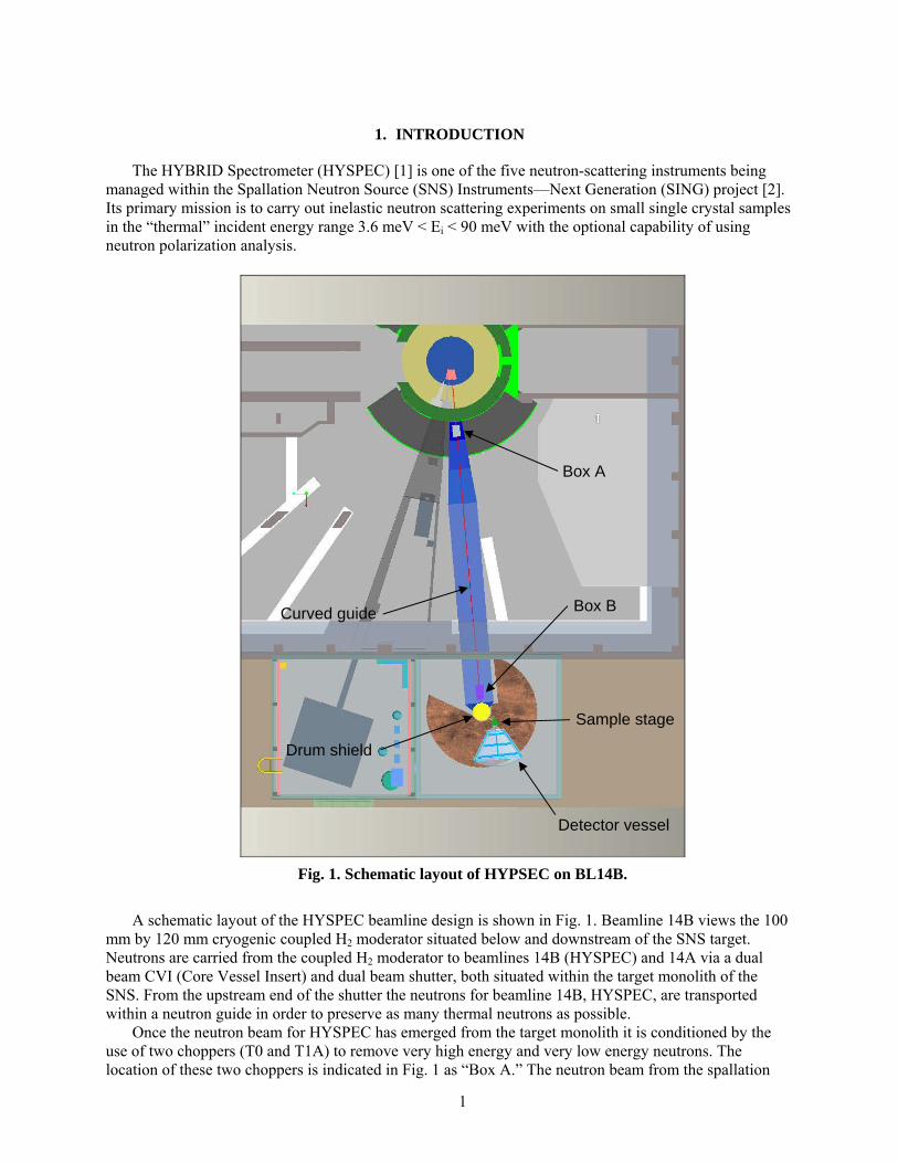
The HYBRID Spectrometer (HYSPEC) [1] is one of the five neutron-scattering instruments being managed within the Spallation Neutron Source (SNS) Instruments—Next Generation (SING) project [2]. Its primary mission is to carry out inelastic neutron scattering experiments on small single crystal samples in the “thermal” incident energy range 3.6 meV < Ei < 90 meV with the optional capability of using neutron polarization analysis.
Fig. 1. Schematic layout of HYPSEC on BL14B.
A schematic layout of the HYSPEC beamline design is shown in Fig. 1. Beamline 14B views the 100
mm by 120 mm cryogenic coupled H2 moderator situated below and downstream of the SNS target. Neutrons are carried from the coupled H2 moderator to beamlines 14B (HYSPEC) and 14A via a dual beam CVI (Core Vessel Insert) and dual beam shutter, both situated within the target monolith of the SNS. From the upstream end of the shutter the neutrons for beamline 14B, HYSPEC, are transported within a neutron guide in order to preserve as many thermal neutrons as possible.
Once the neutron beam for HYSPEC has emerged from the target monolith it is conditioned by the use of two choppers (T0 and T1A) to remove very high energy and very low energy neutrons. The location of these two choppers is indicated in Fig. 1 as “Box A.” The neutron beam from the spallation
Box A
Box B Curved guide
Drum shield
Detector vessel
Sample stage
2
source has a wide spectrum of neutron energies from ~1 GeV downwards. For the HYSPEC instrument we only require incident neutron energies Ei in the thermal range ~3.6 meV < Ei < ~90 meV. The choppers in Box A, work alongside the curved guide and choppers in Box B (to be described shortly), to remove the unwanted neutrons that could cause both radiological and experimental background. The T0 chopper is used to greatly reduce the flux of neutrons in the high energy range (~500 meV to 1 GeV), while the T1A chopper is used to remove neutrons of low energy Ei < ~3.6 meV. These low energy neutrons can lead to a “frame overlap” problem in which they travel so slowly down the beamline that they are overtaken by the neutrons of the desired energy from the next SNS pulse. A detailed discussion of choppers T0 and T1A is given in Sections 2.3.1 and 2.3.2, respectively.
The band of neutrons emerging from Box A is then transported out of the SNS Target Building by a ~23 m long curved neutron guide and delivered to the HYSPEC experimental area, located in an external building, as indicated in Fig. 1. This curved guide also has a filtering function as well as a transport function, removing neutrons with energies in the range ~100 meV < Ei < 500 meV.
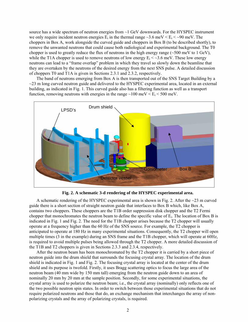
Fig. 2. A schematic 3-d rendering of the HYSPEC experimental area.
A schematic rendering of the HYSPEC experimental area is shown in Fig. 2. After the ~23 m curved guide there is a short section of straight neutron guide that interfaces to Box B which, like Box A, contains two choppers. These choppers are the T1B order suppression disk chopper and the T2 Fermi chopper that monochromates the neutron beam to define the specific value of Ei. The location of Box B is indicated in Fig. 1 and Fig. 2. The need for the T1B chopper arises because the T2 chopper will usually operate at a frequency higher than the 60 Hz of the SNS source. For example, the T2 chopper is anticipated to operate at 180 Hz in many experimental situations. Consequently, the T2 chopper will open multiple times (3 in the example) during an SNS frame and the T1B chopper, which will operate at 60Hz, is required to avoid multiple pulses being allowed through the T2 chopper. A more detailed discussion of the T1B and T2 choppers is given in Sections 2.3.3 and 2.3.4, respectively.
After the neutron beam has been monochromated by the T2 chopper it is carried by a short piece of neutron guide into the drum shield that surrounds the focusing crystal array. The location of the drum shield is indicated in Fig. 1 and Fig. 2. The focusing crystal array is located at the center of the drum shield and its purpose is twofold. Firstly, it uses Bragg scattering optics to focus the large area of the neutron beam (40 mm wide by 150 mm tall) emerging from the neutron guide down to an area of nominally 20 mm by 20 mm at the sample position. Secondly, for some experimental situations, the crystal array is used to polarize the neutron beam; i.e., the crystal array (nominally) only reflects one of the two possible neutron spin states. In order to switch between those experimental situations that do not require polarized neutrons and those that do, an exchange mechanism that interchanges the array of non-polarizing crystals and the array of polarizing crystals, is required.
Box B
Drum shield
Goniometer
Detector vessel
LPSD’s

3
The Bragg scattering process carried out by the focusing crystals causes the direction of the neutron beam to be changed. This directional change depends on the particular neutron energy Ei and, if the angular direction change is denoted by 2θM, it is given by the equation,
⎟⎟⎠
⎞⎜⎜⎝
⎛= −
iMM Ed
81.812
1sin22 1θ (1)
where dM is the crystallographic spacing of the reflecting planes in the crystals in units of Å and the energy Ei is in units of meV. This directional change with incident energy means that it must be possible to change the position of the sample by rotating it about an axis through the center of the focusing crystal array (center of the drum shield). The sample and its sample environment device (for example, a CCR or cryostat), are mounted on a goniometer that allows the sample orientation to be rotated and tilted. The stage on which the goniometer is mounted is carried on air-pads, and is connected by a rigid arm to the drum shield, as illustrated in Fig. 2. The arm, from the drum shield to sample, needs to be able to mount various optional devices for different experimental configurations.
In order to detect the neutrons scattered from the sample a detector vessel is used, as shown in Fig. 2. The vessel is attached by an arm to the sample stage and can be rotated about an axis through the center of the sample. The neutron detectors themselves are Linear Position Sensitive Detector (LPSD) tubes arranged in vertically oriented packs of 8 at the back of the detector vessel. The detector vessel itself will be filled with argon gas which has a much higher transmission for neutrons than air.
At the front of the detector vessel there is space for a number of optional optical devices that can condition the scattered beam from the sample. Firstly, in experimental situations where a polarized beam is not required, a radial collimator can be placed before the front window of the detector vessel. The geometry of the radial collimator will be such that it will remove contaminant scattering from the walls of the sample environment equipment into the scattered beam. Alternatively, if polarization analysis is required in the particular experiment then this radial collimator can be replaced by a polarization analyzer. The radial collimator and polarization analyzer are discussed in more detail in Sections 1.1.1 and 2.2.7, respectively. The data from the array of LPSDs in the detector vessel will be recorded using a standard SNS data acquisition system.
In Section 2 of this document, the various components of the instrument are described in more detail. Section 2 is organized into subsections according to the WBS structure for instruments in the SING project. Section 3 deals with the interfaces that exist between HYSPEC and both other beamlines and the SNS facility, in general.
4
2. SYSTEM REQUIREMENTS AND DESCRIPTION
HYSPEC consists of the following major components. • Detectors • Optical components • Choppers • Sample environment • Shielding • Data acquisition • Instrument-specific support equipment • Instrument infrastructure
The design criteria and a brief description of each of these components are provided in this section.
2.1 DETECTORS
2.1.1 Linear Position-Sensitive Detectors
The detector array on HYSPEC will be an assembly of 160 linear position sensitive detectors (LPSDs) each 1.2 m long by 25 mm diameter. These detectors will be vertically oriented in the detector vessel as shown in Fig. 2 at a radial distance from the sample of 4.5m. Thus within the horizontal plane each detector will subtend an angle of width ~0.23°. The lengths of the detectors will be divided by the electronics into pixels of length 15 mm, which corresponds to an angle of width ~0.20° subtended at the sample position. The timing resolution for each pixel on the LPSD tube should be less than or equal to 1 µs and the dead time of the tube should be no more than 30 µs, corresponding to a linear (proportional) counting regime extending up to 10000 counts/s.
A description of the LPSDs for HYSPEC is given in Section 3.1.4 of the Equipment Specification – Linear Position Sensitive Detector document (107030300-EQ0002-R00) of December 2004 [3]. It should be noted that this specification is identical to that for the SEQUOIA spectrometer given in Section 3.1.5 of Ref. [3].
As described in Section 2.7.2, the detector vessel in which the LPSD tubes will be located will be filled with an argon gas atmosphere, and as a consequence the electronics attached to the LPSD will be designed to operate in such an atmosphere [4].
2.1.2 LPSD Mounting Frame
The LPSD 8-pack modules will be mounted on a structural frame within the argon filled detector vessel. This frame will support and accurately locate 20 modules along with their associated electronics and shielding. The center of each 8 pack will be located on a vertical cylinder with a radius of 4.5 m from the sample position. The detector pack will be tangent to the cylinder at this point. The frame will be designed to provide access to the modules for easy replacement and/or adjustment as required during installation and maintenance operations.
2.1.3 Neutron Beam Monitors
For diagnostics, normalization of count rates and calibration of incident energies, three beam monitors will be placed in the system. A beam monitor is a low-efficiency (~10-3 - 10-5 of the fluence at 3.6 meV < Ei < 90 meV) detector that covers the full area of the beam. One will be placed before the T1B chopper, another immediately after the T2 Fermi chopper and one after the focusing crystal array in the line between the crystal array and the sample (outside of the drum shield). In order to sample the beam
5
before the T1B chopper and after the T2 chopper, the monitors will need to have an active area 40 mm wide by 150 mm tall. It is desirable that the monitors before the T1B chopper, and after the T2 chopper, should be time of flight capable monitors. This will greatly assist in beamline set-up, monitoring and diagnostics. The monitor between the drum shield and sample need not be time of flight capable, although for standardization purposes there is no negative impact if it is time of flight capable.
2.1.4 LPSD 8-Pack Modules
The LPSDs will be grouped in modules of eight on an aluminum-backed structure. The LPSD 8-Pack modules (modules) will serve as the smallest individually replaceable unit of detectors. The modules will be assembled with the LPSDs, an aluminum frame, neutron-absorbing material, preamplifiers, and signal digitizing electronics following the standard SNS design for such modules. The modules will be individually assembled and tested according to a plan set forth by the SNS detector and Data Acquisition Groups [5]. The modules will be designed to plug into the LPSD mounting frame with no additional alignment or adjustment required. If a pack is removed and replaced with another, each pixel will be located to within 2 mm of the original pixel position. The 8-packs will be electrically isolated from the frame and from any neighboring 8-packs. The 8-packs will be able to operate in the argon atmosphere in the detector vessel. The number of 8-packs installed at the completion of the construction project will be 20. The LPSD 8-packs specified for HYSPEC are identical to those specified for the SEQUOIA [6] chopper spectrometer. As a consequence, it will be possible to have a common set of spares for these 8-packs.
2.2 OPTICAL COMPONENTS
2.2.1 Core Vessel Insert
The Core Vessel Insert (CVI) is the interface between beamlines 14A and 14B (HYSPEC) and the core vessel. For HYSPEC the primary criteria in the design of the CVI is that the 40 mm wide by 132 mm tall guide at the start of the shutter insert for beamline 14B should be able to view the full (100 mm wide x 120 mm tall) face of the cryogenic coupled H2 moderator. No instrument is currently specified for beamline 14A and in keeping with earlier practice on beamline 11 the criteria used [7] in the design of the CVI is that beamline 14A should be able to extract a full beam, at least 100 mm wide by 120 mm tall. Ray-tracing calculations [8] have been performed to calculate the internal dimensions of the CVI that satisfy these criteria and appropriate engineering drawings [9] produced subject to these specifications.
2.2.2 Shutter Insert/Guide
For HYSPEC the shutter insert will contain the piece of guide described in Section 2.2.3.1. The shutter insert for HYSPEC will be part of a dual-beam shutter for beamlines 14A and 14B. A steel housing provides the interface between the guide and the shutter insert. The shutter insert will have aluminum alloy 6061 windows to seal it from the environment external to the shutter insert. The shutter insert will be filled with He gas to a nominal pressure of 3 psi (21 kPa) over atmosphere and no higher than 5 psi (34 kPa) over atmosphere. The He gas is provided by SNS Target Systems as described in the Interface Control Document [10].
2.2.3 Beam Line Guide
From the upstream end of the shutter up until 0.3 m before the focusing crystal array the neutron beam on HYSPEC is transported by neutron guides. The purpose of this is to preserve in the beam as many thermal neutrons as is possible, subject to the caveat that those neutrons are capable of being reflected by the focusing crystal array. The guide configuration has been analyzed and optimized by the use of Monte Carlo ray tracing simulations with the McStas package [11]. Detailed results of these simulations are given in Ref. [12].
In the following subsections 2.2.3.1 to 2.2.3.6, and Table 1, we give a summary description of each of the guide sections that resulted from these simulations. A more detailed description of this guide
6
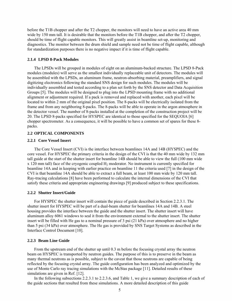
configuration is given in Ref. [13]. In general the guide surfaces are to be coated with m=3 supermirror and in Fig. 3 we show the reflectivity curve used in the simulations for the m=3 case (taken from Ref. [12]).
0.00 0.02 0.04 0.06 0.08 0.10
0.0
0.2
0.4
0.6
0.8
1.0
Guide reflectivity function
Ref
lect
ivity
q0 (A-1)
R0=0.98, m=3,a=5.54, q0=0.022, w=0.0001
Fig. 3. The reflectivity curve used in modeling the supermirror guide
2.2.3.1 Expanding Guide Section in shutter G1A
The neutron guide on HYSPEC begins at the upstream end of the shutter. At this point the guide is 40 mm wide and 132 mm tall with its horizontal and vertical center lines passing through the center of the cryogenic coupled H2 moderator. It should be noted that there is no guide in the CVI and that the inner dimensions of the CVI are such that the upstream window to the guide has a full view of the face of the moderator (see Ref. [8]). This section of guide within the shutter is 1.87 m long with a constant width of 40 mm. However, it expands vertically from the 132 mm at the upstream end to 140 mm at the downstream end of the shutter. All 4 surfaces of the guide will be coated with m=3 supermirror.
An investigation of whether there would be any advantage to tapering the horizontal width of the guide showed that, in terms of the flux of neutrons at the very end of the guide system (in the external building), there was very little, if any, gain in doing this (see Ref. [12]). As noted in subsection 2.2.2, this section of guide within the shutter is maintained in a He gas atmosphere with aluminum windows at each end.
2.2.3.2 Shutter to Box A Expanding Guide Section G1B and Guide G1C
After the shutter the neutron beam passes through the target monolith wall and emerges out into the SNS Target Building and the HYSPEC beamline. In this region the supermirror guide continues to expand vertically from 140 mm at the upstream end to 150 mm at 6.4 m from the moderator. This section of guide is known as G1B. From 6.4m to 8.4m, where it interfaces to the T0 chopper in Box A (see Section 2.2.3.3), the guide has a constant height of 150 mm and is known as G1C. Throughout G1B and
7
G1C the width of the guide is constant at 40 mm and all 4 surfaces of the guide are coated with m=3 supermirror. At the upstream (shutter) end of this section of guide there is a vacuum window, while at the downstream (Box A) end the guide has a windowless interface to Box A and shares the same vacuum as Box A and the following guide sections.
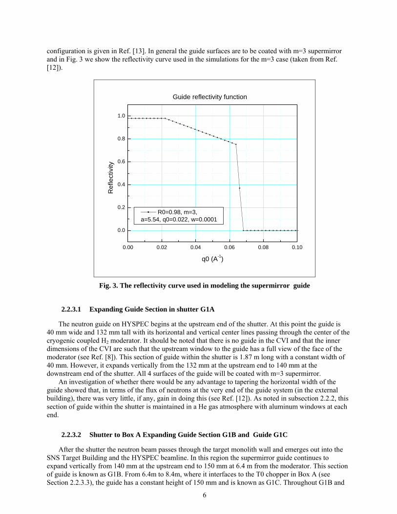
2.2.3.3 Box A Guide
The T0 chopper is located at a distance of 8.5 m from the moderator. The T0 chopper itself is described in Section 2.3.1. Following this at a distance of 9.33 m the T1A frame overlap disk chopper is located. As is common practice nowadays, it is desirable to integrate choppers with a guide in such a way that there is a windowless vacuum connection (i.e., both choppers and guide share a common vacuum). Conceptually the arrangement of guide and choppers is shown in Fig. 4. It should be noted that the dimensions given in Fig. 4 are approximate only. Furthermore, while the combination of the guide and two choppers is referred to as Box A, it does not necessarily have to take the form of a box. The reference to a “box” should be taken as a conceptual “wrapper” for the combination of guide pieces, choppers, mounting fixtures and shielding within the “box” volume in this region. The cross section of guide in Box A is 40 mm wide by 150 mm tall and all surfaces of guide are coated with m=3 supermirror.
Fig. 4. Conceptual layout of the contents of Box A.
2.2.3.4 Curved Guide Section G2
Following Box A, there is a 23.5 m long section of curved guide. The cross section of this guide is 40 mm wide by 150 mm tall. The radius of curvature of this section of guide is 2.305 km. The outer curved surface and the top and bottom sections of the guide are to be coated with m=3 supermirror, while the inner surface is to be coated with m=1. The purpose of a section of curved guide is to ensure that the focusing crystal array in the drum shield is out of “line of sight” of the moderator, i.e. at no point on the exit face of the guide can any point on the entrance face of the guide be seen by a straight ray. For a simple circularly curved guide it can be easily shown that to be out of line of sight in this fashion the exit face of the guide must be displaced by a perpendicular distance of 4x the width of the guide from the position of the entrance face. In the case of the HYSPEC guide layout there are in fact also straight sections of guide, both before and after the curved section. However it is still possible to numerically solve the appropriate equations and determine the displacement that is required to be out of line of sight.
The reason for requiring that the focusing crystal array is out of line of sight of the moderator is related to the reduction of the flux of fast neutrons that arrive at the focusing crystal array and hence must be stopped by the drum shield (see Section 2.5.2). The further out of line of sight the greater the reduction in fast neutron flux.
T0 chopper T1A chopper
Guide
8
For the radius of curvature of 2.305 km for the curved guide section, combined with the lengths of the straight guide sections before and after the curved guide, the focusing crystal array is perpendicularly displaced by 160 mm from the entrance face of the guide in the shutter (see Section 2.2.3.1). Preliminary calculations performed with MCNPX [14]suggest that the combination of the T0 chopper, the curved guide and the drum shield will be sufficient to reduce the radiological levels on the outside of the drum shield to well below those required by the SNS [15]. Further, MCNPX calculations are being performed to verify this in detail.
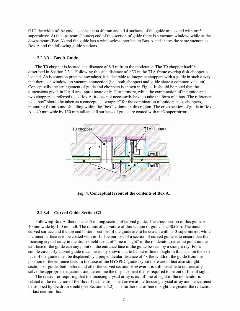
Although the attenuation effect of the curved guide on the thermal neutrons is far less than its effect on the fast neutrons it does still occur. In Fig. 5 we show a comparison (taken from Ref. [12]) of the fluence of neutrons at the end of the straight section of guide G3 (see Section 1.1.1.1) just after the curved section for different displacements of the focusing crystal array. For energies up to ~30 meV there is very little change due to the increasing curvature. However, at 90 meV there is a reduction by a factor of ~2x with a curvature of ~2.305 km corresponding to a displacement of 160 mm. Despite this loss at 90 meV the advantage in terms of using a smaller drum shield diameter (see Section 2.5.2) which is allowed by the fast neutron reduction due to this guide curvature leads us to choose a curvature of ~2.305 km.
0 10 20 30 40 50 60 70 80 90 1001E8
1E9
1E10Fluence at the entranceto Box-B for
offset = 0 cm offset = 12cm offset = 14cm offset = 16cm
Flue
nce(
n/s)
Energy(meV)
Fig. 5. The effect of the guide curvature on the neutron fluence at Box B.
2.2.3.5 Box B Guide
Following the end of the curved guide G2, there is a 1.57 m long piece of guide, 40 mm wide by 150 mm tall, and which is coated on all 4 surfaces with m=3 supermiror. This piece of guide has a windowless interface to the curved guide G2 and Box B, sharing a common vacuum with the rest of the chopper and guide systems. In Box B the T1B and T2 choppers (see Sections 2.3.3 and 2.3.4) are contained. As was the case for the T0 and T1A choppers in Box A, we envisage that the choppers in Box B will have a windowless integration with the guide. A conceptual layout for Box B is shown in Fig. 6.

9
Fig. 6. The conceptual layout of Box B, the drum shield and focusing crystal arrays.
The pieces of guide contained in Box B are all of cross section 40 mm wide by 150 mm tall and are
coated on all 4 surfaces with m=3 supermirror. Also to be contained within Box B is a secondary shutter, whose purpose is to close the beam before
it enters the drum shield. This shutter should contain a portion of the guide so that when the shutter is open the continuity of the neutron transport is preserved and when the shutter is closed this piece of guide is replaced with a sufficient thickness of neutron absorber and steel to stop the beam. This shutter must be integrated with, and controlled by, the Personnel Protection System.
2.2.3.6 Straight Guide Section G4
The final piece of guide is a short section of straight guide G4 that carries the neutron beam from Box B into the drum shield housing the focusing crystals. It has a 40 mm wide by 150 mm tall cross section with all 4 surfaces coated with m=3 supermirror. At the upstream end of this guide there is a windowless connection to Box B, so that the vacuum in guide G4 is common with the vacuum in Box B and the rest of the chopper and guide systems. At the downstream end of G4 (inside the drum shield) there is a vacuum window that terminates the end of the guide system.
Box B guide
Secondary shutter
T1B disk chopper
T2 Fermi chopper
Guide G4 Focusing crystal arrays
10
Table 1. Summary of the nominal parameters for the various guide sections
Width (mm) Height (mm) Guide Section Length of section (m) Entrance Exit Entrance Exit
Supermirror coating
Radius of curvature (km)
G1A 1.87 40 40 132 140 3 --- G1B 2.10 40 40 140 150 3 --- G1C 1.95 40 40 150 150 3 ---
Box A
0.54 0.11
40 40
40 40
150 150
150 150
3 3
--- ---
G2 Outer Inner Top
Bottom
23.51 40 40 150 150 3 1 3 3
2.305
Box B
1.57 0.25 0.78
40 40 40
40 40 40
150 150 150
150 150 150
3 3 3
--- --- ---
G4 0.60 40 40 150 150 3 ---
2.2.4 Focusing Crystals
The 40 mm wide by 150 mm tall beam that emerges from the final guide section G4 (see Section 2.2.3.6) is focused onto the sample (nominally a 20 mm x 20 mm area) by the use of Bragg scattering optics using an array of crystals. The conceptual layout of the focusing crystal array with respect to the guide G4 and the drum shield (see Section 2.5.2) is shown in Fig. 6.
There are two scenarios for this focusing, when experiments are being performed in a non-polarized mode of operation and when they are being performed in a polarized mode. In the former case, HOPG (Highly Oriented Pyrolitic Graphite) crystals can be used for the Bragg scattering optics since these have the highest reflectivity for thermal neutrons. In the situations where a polarized beam is required the HOPG focusing array will be replaced with an array of Heusler (Cu2MnAl) crystals that will polarize the reflected neutron beam. In Sections 2.2.4.1 and 2.2.4.2 respectively, we describe these two cases.
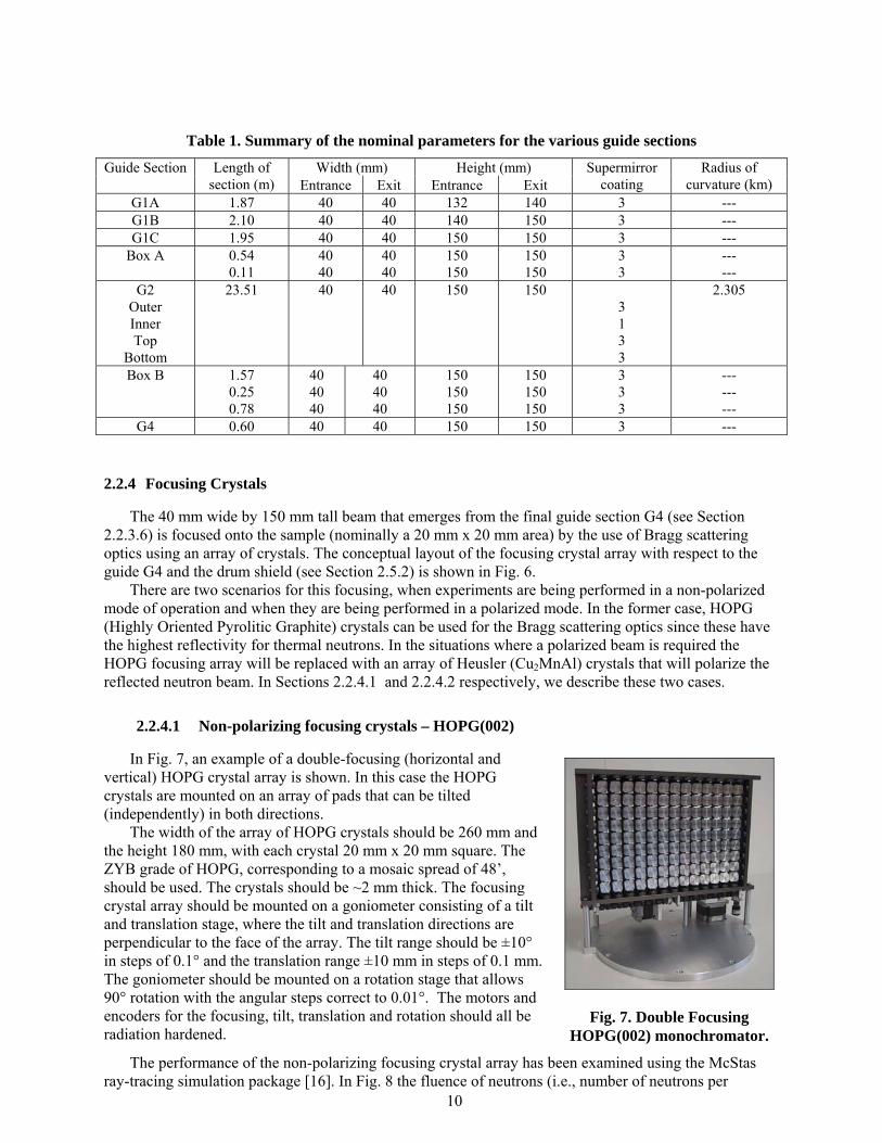
2.2.4.1 Non-polarizing focusing crystals – HOPG(002)
In Fig. 7, an example of a double-focusing (horizontal and vertical) HOPG crystal array is shown. In this case the HOPG crystals are mounted on an array of pads that can be tilted (independently) in both directions.
The width of the array of HOPG crystals should be 260 mm and the height 180 mm, with each crystal 20 mm x 20 mm square. The ZYB grade of HOPG, corresponding to a mosaic spread of 48’, should be used. The crystals should be ~2 mm thick. The focusing crystal array should be mounted on a goniometer consisting of a tilt and translation stage, where the tilt and translation directions are perpendicular to the face of the array. The tilt range should be ±10° in steps of 0.1° and the translation range ±10 mm in steps of 0.1 mm. The goniometer should be mounted on a rotation stage that allows 90° rotation with the angular steps correct to 0.01°. The motors and encoders for the focusing, tilt, translation and rotation should all be radiation hardened.
Fig. 7. Double Focusing HOPG(002) monochromator.
The performance of the non-polarizing focusing crystal array has been examined using the McStas ray-tracing simulation package [16]. In Fig. 8 the fluence of neutrons (i.e., number of neutrons per
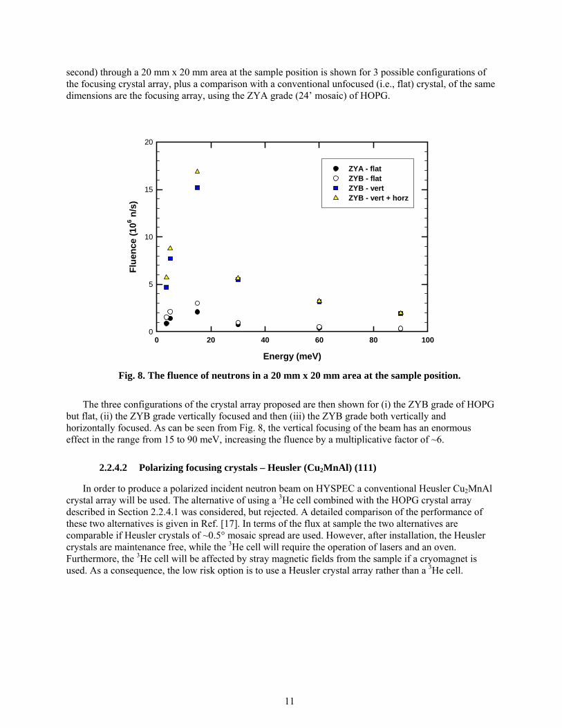
11
second) through a 20 mm x 20 mm area at the sample position is shown for 3 possible configurations of the focusing crystal array, plus a comparison with a conventional unfocused (i.e., flat) crystal, of the same dimensions are the focusing array, using the ZYA grade (24’ mosaic) of HOPG.
Energy (meV)
0 20 40 60 80 100
Flue
nce
(106 n
/s)
0
5
10
15
20
ZYA - flatZYB - flatZYB - vertZYB - vert + horz
Fig. 8. The fluence of neutrons in a 20 mm x 20 mm area at the sample position.
The three configurations of the crystal array proposed are then shown for (i) the ZYB grade of HOPG
but flat, (ii) the ZYB grade vertically focused and then (iii) the ZYB grade both vertically and horizontally focused. As can be seen from Fig. 8, the vertical focusing of the beam has an enormous effect in the range from 15 to 90 meV, increasing the fluence by a multiplicative factor of ~6.
2.2.4.2 Polarizing focusing crystals – Heusler (Cu2MnAl) (111)
In order to produce a polarized incident neutron beam on HYSPEC a conventional Heusler Cu2MnAl crystal array will be used. The alternative of using a 3He cell combined with the HOPG crystal array described in Section 2.2.4.1 was considered, but rejected. A detailed comparison of the performance of these two alternatives is given in Ref. [17]. In terms of the flux at sample the two alternatives are comparable if Heusler crystals of ~0.5° mosaic spread are used. However, after installation, the Heusler crystals are maintenance free, while the 3He cell will require the operation of lasers and an oven. Furthermore, the 3He cell will be affected by stray magnetic fields from the sample if a cryomagnet is used. As a consequence, the low risk option is to use a Heusler crystal array rather than a 3He cell.
12
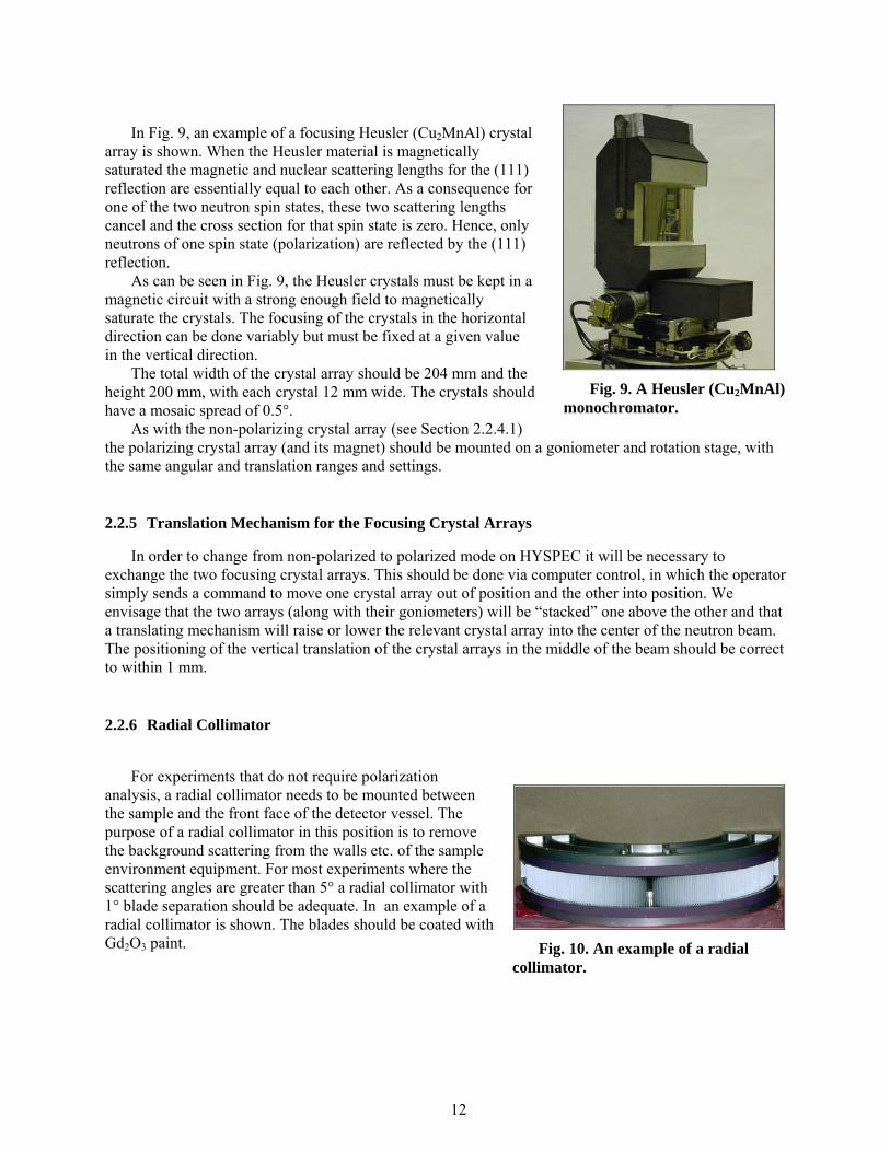
In Fig. 9, an example of a focusing Heusler (Cu2MnAl) crystal
array is shown. When the Heusler material is magnetically saturated the magnetic and nuclear scattering lengths for the (111) reflection are essentially equal to each other. As a consequence for one of the two neutron spin states, these two scattering lengths cancel and the cross section for that spin state is zero. Hence, only neutrons of one spin state (polarization) are reflected by the (111) reflection.
As can be seen in Fig. 9, the Heusler crystals must be kept in a magnetic circuit with a strong enough field to magnetically saturate the crystals. The focusing of the crystals in the horizontal direction can be done variably but must be fixed at a given value in the vertical direction.
The total width of the crystal array should be 204 mm and the height 200 mm, with each crystal 12 mm wide. The crystals should have a mosaic spread of 0.5°.
As with the non-polarizing crystal array (see Section 2.2.4.1)
Fig. 9. A Heusler (Cu2MnAl)
monochromator.
the polarizing crystal array (and its magnet) should be mounted on a goniometer and rotation stage, with the same angular and translation ranges and settings.
2.2.5 Translation Mechanism for the Focusing Crystal Arrays
In order to change from non-polarized to polarized mode on HYSPEC it will be necessary to exchange the two focusing crystal arrays. This should be done via computer control, in which the operator simply sends a command to move one crystal array out of position and the other into position. We envisage that the two arrays (along with their goniometers) will be “stacked” one above the other and that a translating mechanism will raise or lower the relevant crystal array into the center of the neutron beam. The positioning of the vertical translation of the crystal arrays in the middle of the beam should be correct to within 1 mm.
2.2.6 Radial Collimator
For experiments that do not require polarization
analysis, a radial collimator needs to be mounted between the sample and the front face of the detector vessel. The purpose of a radial collimator in this position is to remove the background scattering from the walls etc. of the sample environment equipment. For most experiments where the scattering angles are greater than 5° a radial collimator with 1° blade separation should be adequate. In an example of a radial collimator is shown. The blades should be coated with Gd2O3 paint.
Fig. 10. An example of a radial
collimator.
13
2.2.7 Wide Angle Supermirror Polarization Analyzer
The combination of the Heusler crystal array described in Section 2.2.4.2 and the Mezei polarization flipper described in Section 2.4.2.1 means that incident neutron beams with both spin polarizations can be produced on HYSPEC. However, in order to carry out experiments with full polarization analysis, it is also necessary to be able to analyze the scattered beam from the sample in such a way that both of the scattered neutron polarization states can be separated. Furthermore, the polarization analyzer system needs to able to perform this analysis over the horizontal angular range of 60° subtended by the detector vessel (see Section 2.7.2). While it would be desirable to be able to cover the full vertical angular range of ±7.5° subtended by the detector vessel, the most important part of this range to cover is that close to the horizontal plane of ±3.7°.
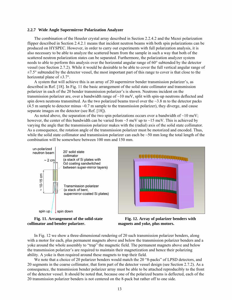
A system that will achieve this is an array of 20 supermirror bender transmission polarizer’s, as described in Ref. [18]. In Fig. 11 the basic arrangement of the solid state collimator and transmission polarizer in each of the 20 bender transmission polarizer’s is shown. Neutrons incident on the transmission polarizer are, over a bandwidth range of ~10 meV, split with spin-up neutrons deflected and spin down neutrons transmitted. As the two polarized beams travel over the ~3.8 m to the detector packs (4.5 m sample to detector minus ~0.7 m sample to the transmission polarizer), they diverge, and cause separate images on the detector (see Ref. [18]).
As noted above, the separation of the two spin polarizations occurs over a bandwidth of ~10 meV; however, the center of this bandwidth can be varied from ~5 meV up to ~15 meV. This is achieved by varying the angle that the transmission polarizer makes with the (radial) axis of the solid state collimator. As a consequence, the rotation angle of the transmission polarizer must be motorized and encoded. Thus, while the solid state collimator and transmission polarizer can each be ~50 mm long the total length of the combination will be somewhere between 100 mm and 150 mm.
Fig. 11. Arrangement of the solid-state
collimator and bender polarizer. Fig. 12. Array of polarizer benders with
magnets and yoke, plus motors.
In Fig. 12 we show a three-dimensional rendering of 20 such transmission polarizer benders, along
with a motor for each, plus permanent magnets above and below the transmission polarizer benders and a yoke around the whole assembly to “trap” the magnetic field. The permanent magnets above and below the transmission polarizer’s are required to maintain their magnetization and hence their polarizing ability. A yoke is then required around these magnets to trap their field.
We note that a choice of 20 polarizer benders would match the 20 “8-packs” of LPSD detectors, and 20 segments in the coarse collimator, that form part of the detector vessel design (see Section 2.7.2). As a consequence, the transmission bender polarizer array must be able to be attached reproducibly to the front of the detector vessel. It should be noted that, because one of the polarized beams is deflected, each of the 20 transmission polarizer benders is not centered on the 8-pack but rather off to one side.
14
In order that the SNS 15 T compensated cryomagnet can be used with this polarization analyzer the front face of the device must lie outside of a radial distance of ~ 0.55 m from the sample position. This means that the supermirror polarizer’s themselves will be at a distance of ~0.7 m from the sample. In order to cover the vertical angle of of ±3.7° the polarizing mirrors will need to be ~90 mm tall at this distance. The blades of the solid state collimator should be a similar height. The active width of the collimator and polarizer should be 20 mm.
2.3 CHOPPERS
There are four choppers to be used on HYSPEC, two of them in Box A and two in Box B. A detailed description of the specifications for these choppers is given in Ref. [19]. In the following subsections we outline these choppers.
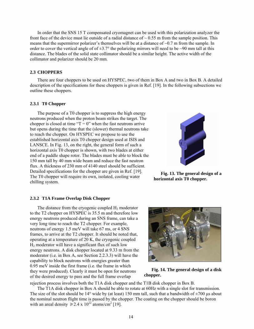
2.3.1 T0 Chopper
The purpose of a T0 chopper is to suppress the high energy neutrons produced when the proton beam strikes the target. The chopper is closed at time “T = 0” when the fast neutrons arrive but opens during the time that the (slower) thermal neutrons take to reach the chopper. On HYSPEC we propose to use the established horizontal axis T0 chopper design used at ISIS and LANSCE. In Fig. 13, on the right, the general form of such a horizontal axis T0 chopper is shown, with two blades at either end of a paddle shape rotor. The blades must be able to block the 150 mm tall by 40 mm wide beam and reduce the fast neutron flux. A thickness of 230 mm of 4140 steel should be sufficient. Detailed specifications for the chopper are given in Ref. [19]. The T0 chopper will require its own, isolated, cooling water chilling system.
Fig. 13. The general design of a horizontal axis T0 chopper.
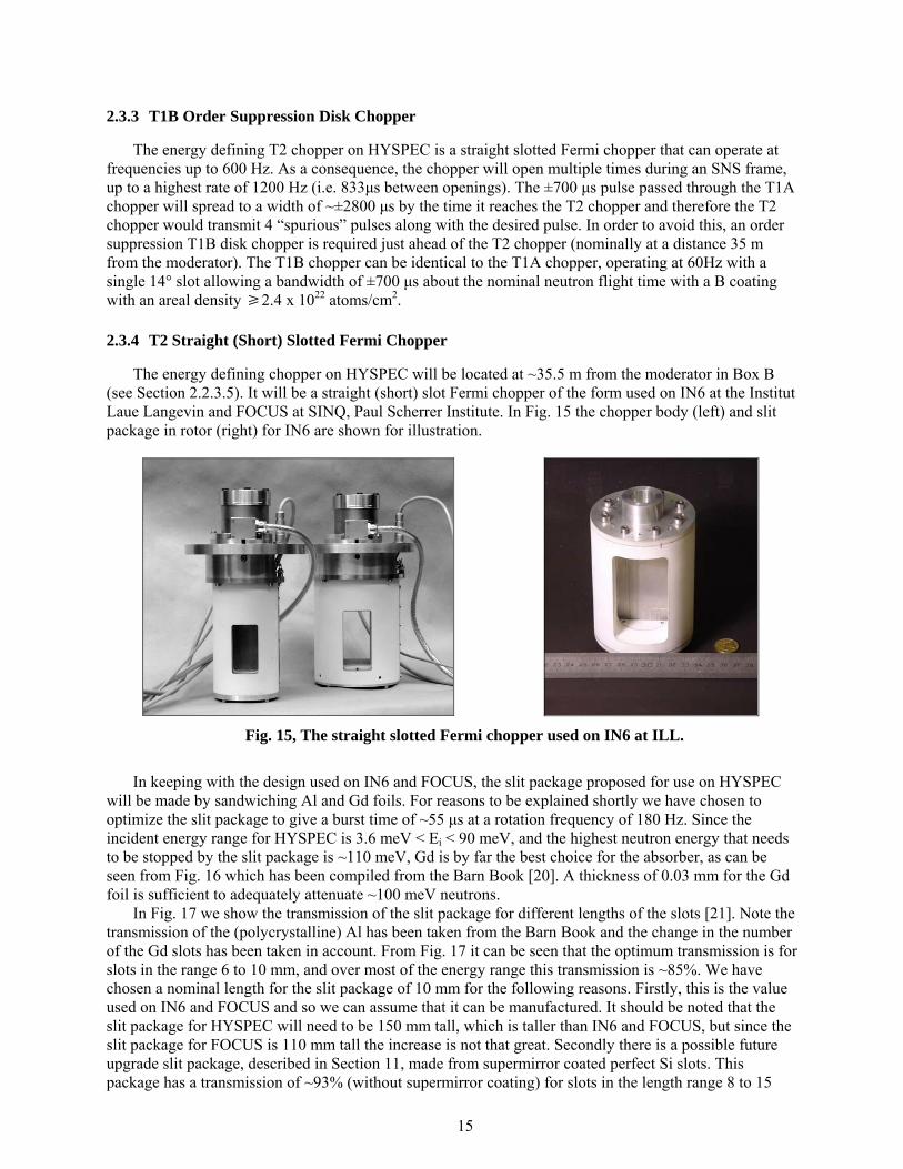
2.3.2 T1A Frame Overlap Disk Chopper
The distance from the cryogenic coupled H2 moderator to the T2 chopper on HYSPEC is 35.5 m and therefore low energy neutrons produced during an SNS frame, can take a very long time to reach the T2 chopper. For example, neutrons of energy 1.5 meV will take 67 ms, or 4 SNS frames, to arrive at the T2 chopper. It should be noted that, operating at a temperature of 20 K, the cryogenic coupled H2 moderator will have a significant flux of such low energy neutrons. A disk chopper located at 9.33 m from the moderator (i.e. in Box A, see Section 2.2.3.3) will have the capability to block neutrons with energies greater than 0.95 meV inside the first frame (i.e. the frame in which they were produced). Clearly it must be open for neutrons of the desired energy to pass and the full frame overlap
Fig. 14. The general design of a disk chopper.
rejection process involves both the T1A disk chopper and the T1B disk chopper in Box B. The T1A disk chopper in Box A should be able to rotate at 60Hz with a single slot for transmission.
The size of the slot should be 14° wide by (at least) 150 mm tall, such that a bandwidth of ±700 µs about the nominal neutron flight time is passed by the chopper. The coating on the chopper should be boron with an areal density 2.4 x 10²² atoms/cm2 [19].
15
2.3.3 T1B Order Suppression Disk Chopper
The energy defining T2 chopper on HYSPEC is a straight slotted Fermi chopper that can operate at frequencies up to 600 Hz. As a consequence, the chopper will open multiple times during an SNS frame, up to a highest rate of 1200 Hz (i.e. 833µs between openings). The ±700 µs pulse passed through the T1A chopper will spread to a width of ~±2800 µs by the time it reaches the T2 chopper and therefore the T2 chopper would transmit 4 “spurious” pulses along with the desired pulse. In order to avoid this, an order suppression T1B disk chopper is required just ahead of the T2 chopper (nominally at a distance 35 m from the moderator). The T1B chopper can be identical to the T1A chopper, operating at 60Hz with a single 14° slot allowing a bandwidth of ±700 µs about the nominal neutron flight time with a B coating with an areal density 2.4 x 10²² atoms/cm2.
2.3.4 T2 Straight (Short) Slotted Fermi Chopper
The energy defining chopper on HYSPEC will be located at ~35.5 m from the moderator in Box B (see Section 2.2.3.5). It will be a straight (short) slot Fermi chopper of the form used on IN6 at the Institut Laue Langevin and FOCUS at SINQ, Paul Scherrer Institute. In Fig. 15 the chopper body (left) and slit package in rotor (right) for IN6 are shown for illustration.
Fig. 15, The straight slotted Fermi chopper used on IN6 at ILL.
In keeping with the design used on IN6 and FOCUS, the slit package proposed for use on HYSPEC
will be made by sandwiching Al and Gd foils. For reasons to be explained shortly we have chosen to optimize the slit package to give a burst time of ~55 µs at a rotation frequency of 180 Hz. Since the incident energy range for HYSPEC is 3.6 meV < Ei < 90 meV, and the highest neutron energy that needs to be stopped by the slit package is ~110 meV, Gd is by far the best choice for the absorber, as can be seen from Fig. 16 which has been compiled from the Barn Book [20]. A thickness of 0.03 mm for the Gd foil is sufficient to adequately attenuate ~100 meV neutrons.
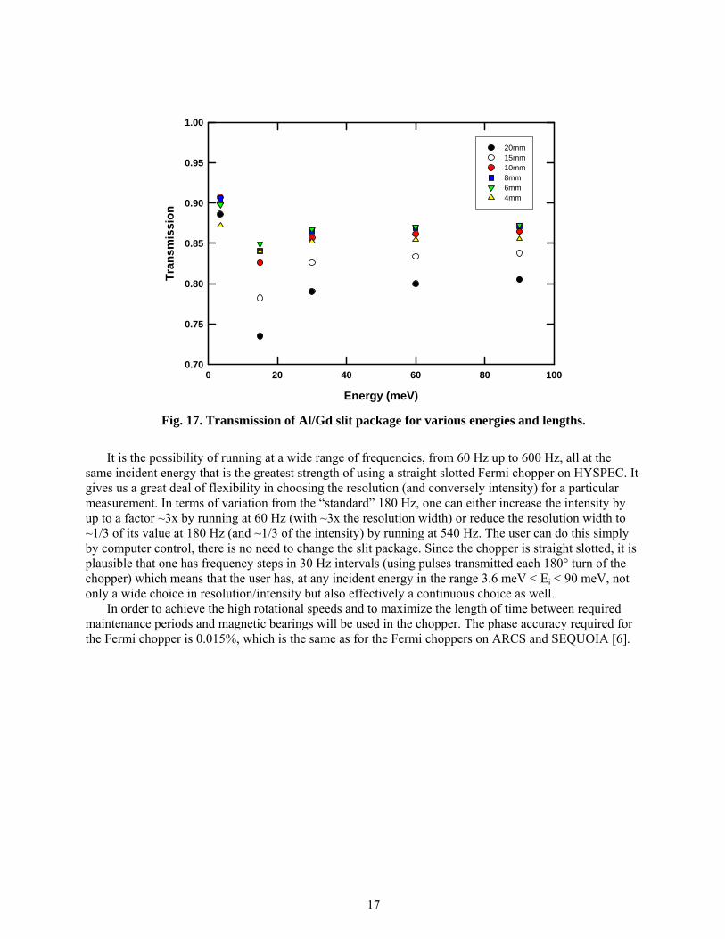
In Fig. 17 we show the transmission of the slit package for different lengths of the slots [21]. Note the transmission of the (polycrystalline) Al has been taken from the Barn Book and the change in the number of the Gd slots has been taken in account. From Fig. 17 it can be seen that the optimum transmission is for slots in the range 6 to 10 mm, and over most of the energy range this transmission is ~85%. We have chosen a nominal length for the slit package of 10 mm for the following reasons. Firstly, this is the value used on IN6 and FOCUS and so we can assume that it can be manufactured. It should be noted that the slit package for HYSPEC will need to be 150 mm tall, which is taller than IN6 and FOCUS, but since the slit package for FOCUS is 110 mm tall the increase is not that great. Secondly there is a possible future upgrade slit package, described in Section 11, made from supermirror coated perfect Si slots. This package has a transmission of ~93% (without supermirror coating) for slots in the length range 8 to 15

16
mm. Thus, 10 mm is a length that works both for the established slit package design and for a possible future upgrade.
1 10 100 1000100
101
102
103
104
105
106
nat. boron nat.gadolinium Li6 cadmium
Tota
l cro
ss-s
ectio
n (b
arns
)
Energy(meV)
Fig. 16. The total cross sections for various absorbing materials.
Monte Carlo ray tracing simulations [22] of the straight slotted Fermi chopper have been carried out
using the flux distribution from the coupled H2 moderator and the guide system proposed for HYSPEC. In Table 2 we give the burst times and energy widths of the neutron pulse produced by the Fermi chopper operating at frequencies of 180 Hz (standard), 60 Hz and 360 Hz. It should be noted that the simulation results reported here have been carried out using 100% transmission for the slots and no supermirror coating (results for simulations including the supermirror coating are given in Section 11).
Table 2. The burst times and incident energy widths for the Fermi chopper.
180Hz 60Hz 360Hz Energy (meV) ∆T (µs) ∆Ei (meV) ∆T (µs) ∆Ei (meV) ∆T (µs) ∆Ei (meV)
3.6 56 0.032 172 0.047 29 0.032 5.0 55 0.046 169 0.072 29 0.044 15 55 0.166 167 0.331 27 0.132 30 55 0.308 166 0.820 27 0.200 60 55 0.800 162 2.053 26 0.413 90 51 1.325 162 3.399 26 0.701
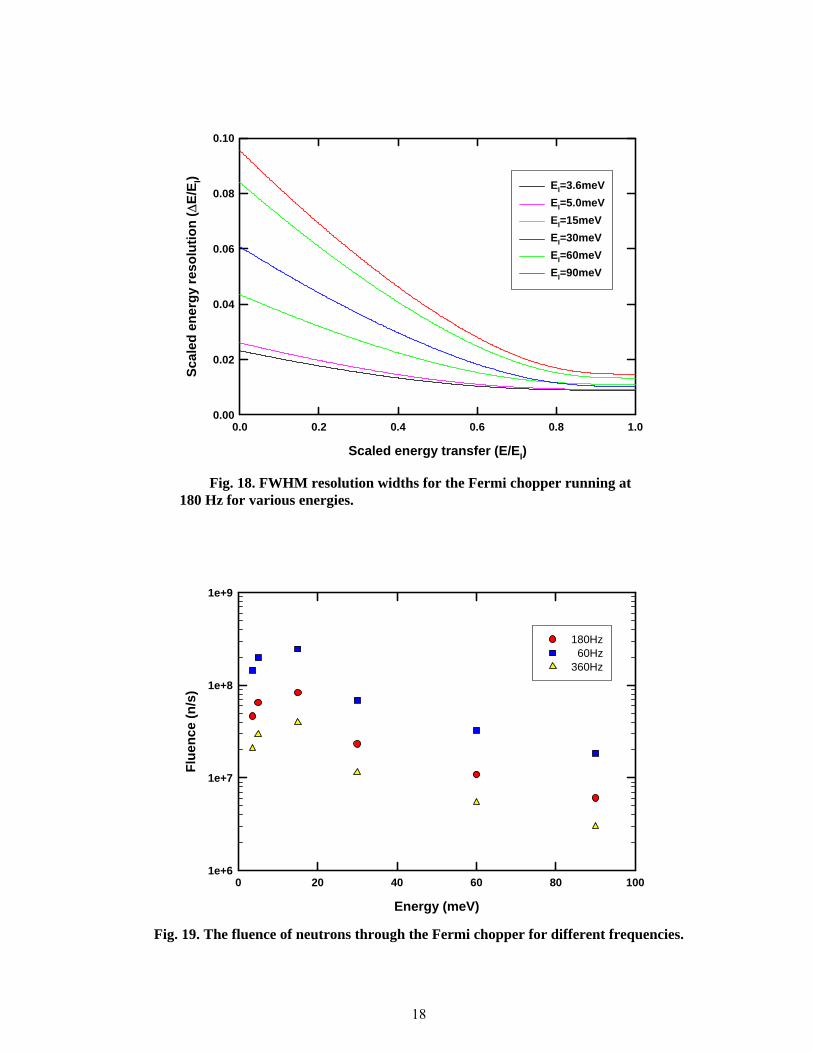
The resolution widths calculated from the burst times and incident energy widths given in Table 2 for
the 180 Hz rotation frequency are shown in Fig. 18 in terms of scaled energies (both the width and energy transfer are divided by the incident energy). The fluence (total number of neutrons per second) through the chopper running at 180 Hz is shown in Fig. 19 by the red circles. Also shown in Fig. 19 is the fluence if the chopper is run at 60 Hz (blue squares) and 360 Hz (green triangles). The effect on the burst time and incident energy width of running at these other frequencies can be seen from the values in Table 2.
17
Energy (meV)
0 20 40 60 80 100
Tran
smis
sion
0.70
0.75
0.80
0.85
0.90
0.95
1.00
20mm15mm10mm8mm6mm4mm
Fig. 17. Transmission of Al/Gd slit package for various energies and lengths.
It is the possibility of running at a wide range of frequencies, from 60 Hz up to 600 Hz, all at the
same incident energy that is the greatest strength of using a straight slotted Fermi chopper on HYSPEC. It gives us a great deal of flexibility in choosing the resolution (and conversely intensity) for a particular measurement. In terms of variation from the “standard” 180 Hz, one can either increase the intensity by up to a factor ~3x by running at 60 Hz (with ~3x the resolution width) or reduce the resolution width to ~1/3 of its value at 180 Hz (and ~1/3 of the intensity) by running at 540 Hz. The user can do this simply by computer control, there is no need to change the slit package. Since the chopper is straight slotted, it is plausible that one has frequency steps in 30 Hz intervals (using pulses transmitted each 180° turn of the chopper) which means that the user has, at any incident energy in the range 3.6 meV < Ei < 90 meV, not only a wide choice in resolution/intensity but also effectively a continuous choice as well.
In order to achieve the high rotational speeds and to maximize the length of time between required maintenance periods and magnetic bearings will be used in the chopper. The phase accuracy required for the Fermi chopper is 0.015%, which is the same as for the Fermi choppers on ARCS and SEQUOIA [6].
18
Scaled energy transfer (E/EI)
0.0 0.2 0.4 0.6 0.8 1.0
Scal
ed e
nerg
y re
solu
tion
( ∆E/
E I)
0.00
0.02
0.04
0.06
0.08
0.10
EI=3.6meVEI=5.0meVEI=15meVEI=30meVEI=60meVEI=90meV
Fig. 18. FWHM resolution widths for the Fermi chopper running at
180 Hz for various energies.
Energy (meV)
0 20 40 60 80 100
Flue
nce
(n/s
)
1e+6
1e+7
1e+8
1e+9
180Hz 60Hz360Hz
Fig. 19. The fluence of neutrons through the Fermi chopper for different frequencies.
19
2.4 SAMPLE ENVIRONMENT
2.4.1 Sample Stage and Goniometer
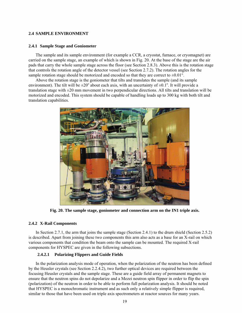
The sample and its sample environment (for example a CCR, a cryostat, furnace, or cryomagnet) are carried on the sample stage, an example of which is shown in Fig. 20. At the base of the stage are the air pads that carry the whole sample stage across the floor (see Section 2.8.3). Above this is the rotation stage that controls the rotation angle of the detector vessel (see Section 2.7.2). The rotation angles for the sample rotation stage should be motorized and encoded so that they are correct to ±0.01°.
Above the rotation stage is the goniometer that tilts and translates the sample (and its sample environment). The tilt will be ±20o about each axis, with an uncertainty of ±0.1o. It will provide a translation stage with ±20 mm movement in two perpendicular directions. All tilts and translation will be motorized and encoded. This system should be capable of handling loads up to 300 kg with both tilt and translation capabilities.
Fig. 20. The sample stage, goniometer and connection arm on the IN1 triple axis.
2.4.2 X-Rail Components
In Section 2.7.1, the arm that joins the sample stage (Section 2.4.1) to the drum shield (Section 2.5.2) is described. Apart from joining these two components this arm also acts as a base for an X-rail on which various components that condition the beam onto the sample can be mounted. The required X-rail components for HYSPEC are given in the following subsections.
2.4.2.1 Polarizing Flippers and Guide Fields
In the polarization analysis mode of operation, when the polarization of the neutron has been defined by the Heusler crystals (see Section 2.2.4.2), two further optical devices are required between the focusing Heusler crystals and the sample stage. These are a guide field array of permanent magnets to ensure that the neutron spins do not depolarize and a Mezei neutron spin flipper in order to flip the spin (polarization) of the neutron in order to be able to perform full polarization analysis. It should be noted that HYSPEC is a monochromatic instrument and as such only a relatively simple flipper is required, similar to those that have been used on triple axis spectrometers at reactor sources for many years.
20
The dimensions of the flipper and guide field can be estimated from the sizes of the focusing crystal arrays (see Section 2.2.4.2) and the nominal sample size (20 mm x 20 mm), along with the estimated radius of the drum shield of 0.9 m (see Section 2.5.2). Using these dimensions, a flipper and guide field with an active height of 120 mm and width of 50 mm is adequate.
2.4.2.2 Soller Collimators
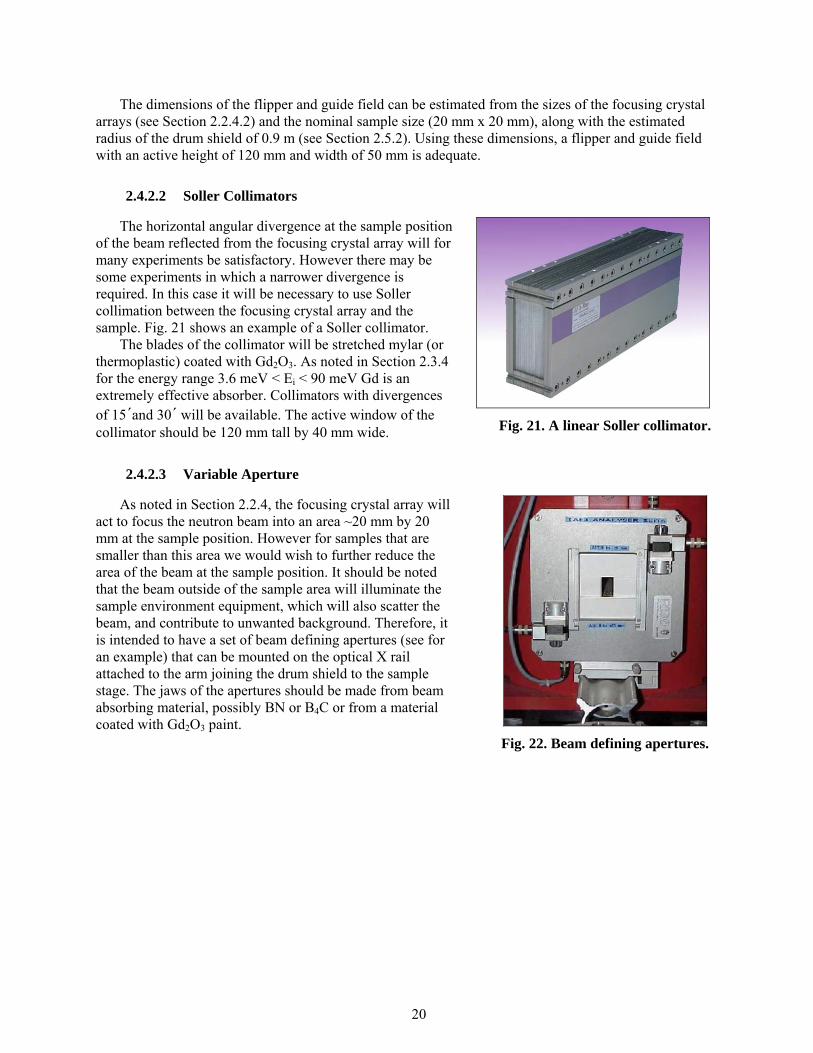
The horizontal angular divergence at the sample position of the beam reflected from the focusing crystal array will for many experiments be satisfactory. However there may be some experiments in which a narrower divergence is required. In this case it will be necessary to use Soller collimation between the focusing crystal array and the sample. Fig. 21 shows an example of a Soller collimator.
The blades of the collimator will be stretched mylar (or thermoplastic) coated with Gd2O3. As noted in Section 2.3.4 for the energy range 3.6 meV < Ei < 90 meV Gd is an extremely effective absorber. Collimators with divergences of 15´and 30´ will be available. The active window of the collimator should be 120 mm tall by 40 mm wide.
Fig. 21. A linear Soller collimator.
2.4.2.3 Variable Aperture
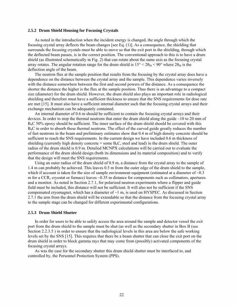
As noted in Section 2.2.4, the focusing crystal array will act to focus the neutron beam into an area ~20 mm by 20 mm at the sample position. However for samples that are smaller than this area we would wish to further reduce the area of the beam at the sample position. It should be noted that the beam outside of the sample area will illuminate the sample environment equipment, which will also scatter the beam, and contribute to unwanted background. Therefore, it is intended to have a set of beam defining apertures (see for an example) that can be mounted on the optical X rail attached to the arm joining the drum shield to the sample stage. The jaws of the apertures should be made from beam absorbing material, possibly BN or B4C or from a material coated with Gd2O3 paint.
Fig. 22. Beam defining apertures.

21
2.5 SHIELDING
2.5.1 Beam Line Shielding
To ensure that the HYSPEC beamline will meet all SNS requirements [15] for radiation levels substantial amounts of shielding will be placed around the various sections of the beamline. The conceptual design of the shielding for the beamline makes significant use of MCNPX simulation techniques to evaluate the effectiveness of the shielding composition and thickness. The shielding design for the HYSPEC beamline out to the edge of the SNS Target Building is shown in Fig. 23 [24].
Fig. 23. The provisional layout of the beamline shielding.
In the external building there are two sections of shielding that surround the beamline, that which
surrounds Box B and the drum shield that surrounds the focusing crystals. Furthermore the experimental area in the external building is surrounded by a shielding wall to create an interlocked exclusion zone when the shutters are open and the beam is on. The drum shield is discussed separately in Section 2.5.2 and the sample area exclusion zone in Section 2.8.4.
The shielding will be a mix of light or heavy concrete and steel. Where feasible, this will be poured in place, using appropriate material to subdivide it into removable sections. Additionally, precast blocks of concrete will be used. The initial shielding model [24] is as follows. For the first 11 to 15 m of the beamline the shielding immediately adjacent to the beam line will consist of ~0.4 m thick steel. Outside of the steel in the first 11.4 m, the shielding will be heavy concrete (HDC) and then light concrete (OC) from 11.4 to 15 m. Beyond this, out to ~33 m, the shielding will be light concrete with steel plate (~10 mm) backing the guide. In the region around Box B in the external building it may be necessary to again use steel (or perhaps some lead/steel combination) alongside the light concrete. The T1B and T2 choppers in box B will emit gamma rays when neutrons are absorbed by the slits/disk and some metallic shielding (lead or steel) will be required to shield against these gamma rays. Currently a layer of 0.4 m of steel has been included; however this will be revised when appropriate MCNPX shielding calculations become available.
The structural support for the shielding will be designed in concert with the supports for the beam line guide to minimize displacement of the guide once the shielding is installed.
22
2.5.2 Drum Shield Housing for Focusing Crystals
As noted in the introduction when the incident energy is changed, the angle through which the focusing crystal array deflects the beam changes [see Eq. (1)]. As a consequence, the shielding that surrounds the focusing crystals must be able to move so that the exit port in the shielding, through which the deflected beam passes, is in the correct position. The conventional approach to this is to have a drum shield (as illustrated schematically in Fig. 2) that can rotate about the same axis as the focusing crystal array rotates. The angular rotation range for the drum shield is 15° < 2θM < 90° where 2θM is the deflection angle of the beam.
The neutron flux at the sample position that results from the focusing by the crystal array does have a dependence on the distance between the crystal array and the sample. This dependence varies inversely with the distance somewhere between the first and second powers of the distance. As a consequence the shorter the distance the higher is the flux at the sample position. Thus there is an advantage to a compact size (diameter) for the drum shield. However, the drum shield also plays an important role in radiological shielding and therefore must have a sufficient thickness to ensure that the SNS requirements for dose rate are met [15]. It must also have a sufficient internal diameter such that the focusing crystal arrays and their exchange mechanism can be adequately contained.
An internal diameter of 0.6 m should be sufficient to contain the focusing crystal arrays and their devices. In order to stop the thermal neutrons that enter the drum shield along the guide ~10 to 20 mm of B4C 50% epoxy should be sufficient. The inner surface of the drum shield should be covered with this B4C in order to absorb these thermal neutrons. The effect of the curved guide greatly reduces the number of fast neutrons in the beam and preliminary estimates show that 0.4 m of high density concrete should be sufficient to reach the SNS requirements. In the current design we have included 0.6 m thickness of shielding (currently high density concrete + some B4C, steel and lead) in the drum shield. The outer radius of the drum shield is 0.9 m. Detailed MCNPX calculations will be carried out to evaluate the performance of the drum shield design (both its dimensions and its material composition) and to verify that the design will meet the SNS requirements.
Using an outer radius of the drum shield of 0.9 m, a distance from the crystal array to the sample of 1.4 m can probably be achieved. This leaves 0.5 m from the outer edge of the drum shield to the sample, which if account is taken for the size of sample environment equipment (estimated at a diameter of ~0.3 m for a CCR, cryostat or furnace) leaves ~0.35 m distance for components such as collimators, apertures and a monitor. As noted in Section 2.7.1, for polarized neutron experiments where a flipper and guide field must be included, this distance will not be sufficient. It will also not be sufficient if the SNS compensated cryomagnet, which has a diameter of ~1 m, is used on HYSPEC. As discussed in Section 2.7.1 the arm from the drum shield will be extendable so that the distance from the focusing crystal array to the sample stage can be changed for different experimental configurations.
2.5.3 Drum Shield Shutter
In order for users to be able to safely access the area around the sample and detector vessel the exit port from the drum shield to the sample must be shut (as well as the secondary shutter in Box B (see Section 2.2.3.5 ) in order to ensure that the radiological levels in this area are below the safe working levels set by the SNS [15]. This requires that there be a beam shutter that can close the exit port on the drum shield in order to block gamma rays that may come from (possibly) activated components of the focusing crystal arrays.
As was the case for the secondary shutter this drum shield shutter must be interfaced to, and controlled by, the Personnel Protection System (PPS).
23
2.5.4 Detector Vessel Shielding
The detector vessel (see Section 2.7.2) will be internally shielded to avoid scattering of neutrons from the inside faces of the detector walls. Since the neutrons that enter through the front window of the detector vessel will be thermal neutrons this internal shielding can be done very simply by covering the interior (aluminum plate) surfaces of the detector vessel with B4C “crispy-mix”. 2.5.5 Beam Stop
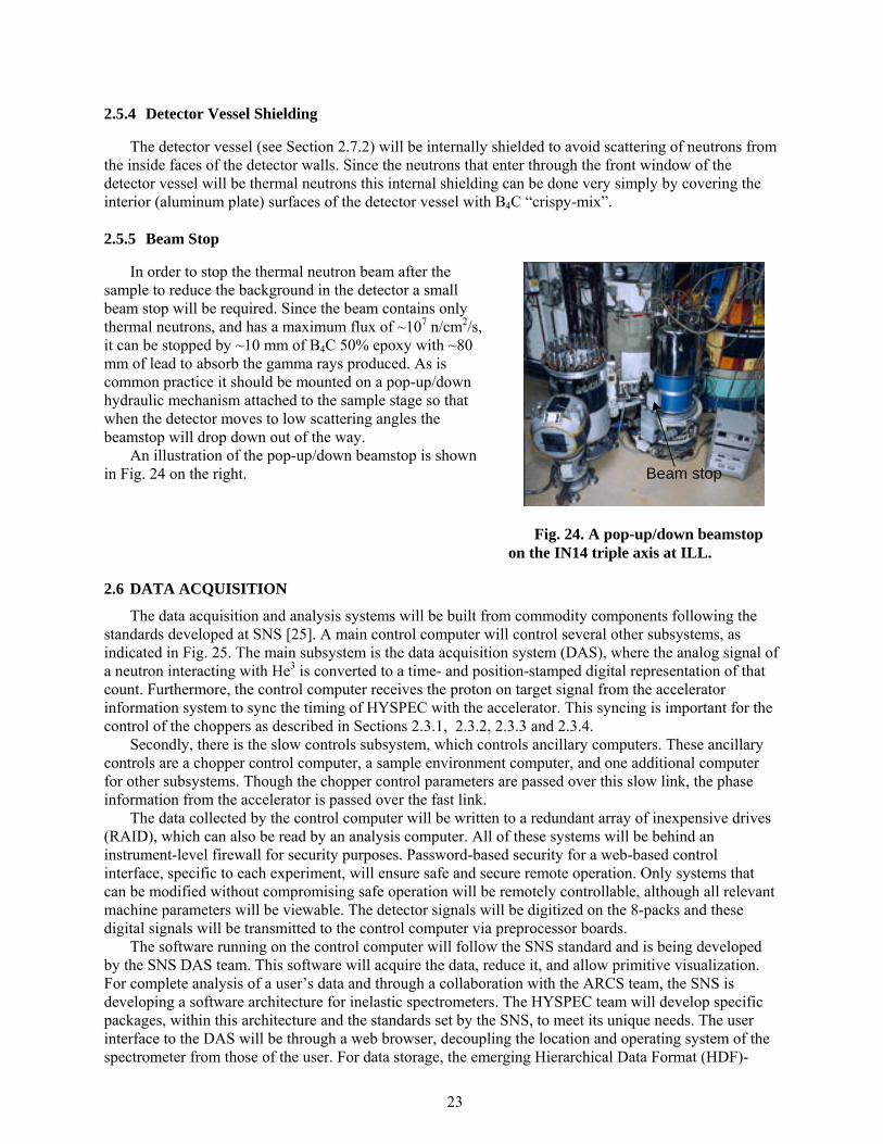
In order to stop the thermal neutron beam after the sample to reduce the background in the detector a small beam stop will be required. Since the beam contains only thermal neutrons, and has a maximum flux of ~107 n/cm2/s, it can be stopped by ~10 mm of B4C 50% epoxy with ~80 mm of lead to absorb the gamma rays produced. As is common practice it should be mounted on a pop-up/down hydraulic mechanism attached to the sample stage so that when the detector moves to low scattering angles the beamstop will drop down out of the way.
An illustration of the pop-up/down beamstop is shown in Fig. 24 on the right.
Fig. 24. A pop-up/down beamstop on the IN14 triple axis at ILL.
2.6 DATA ACQUISITION
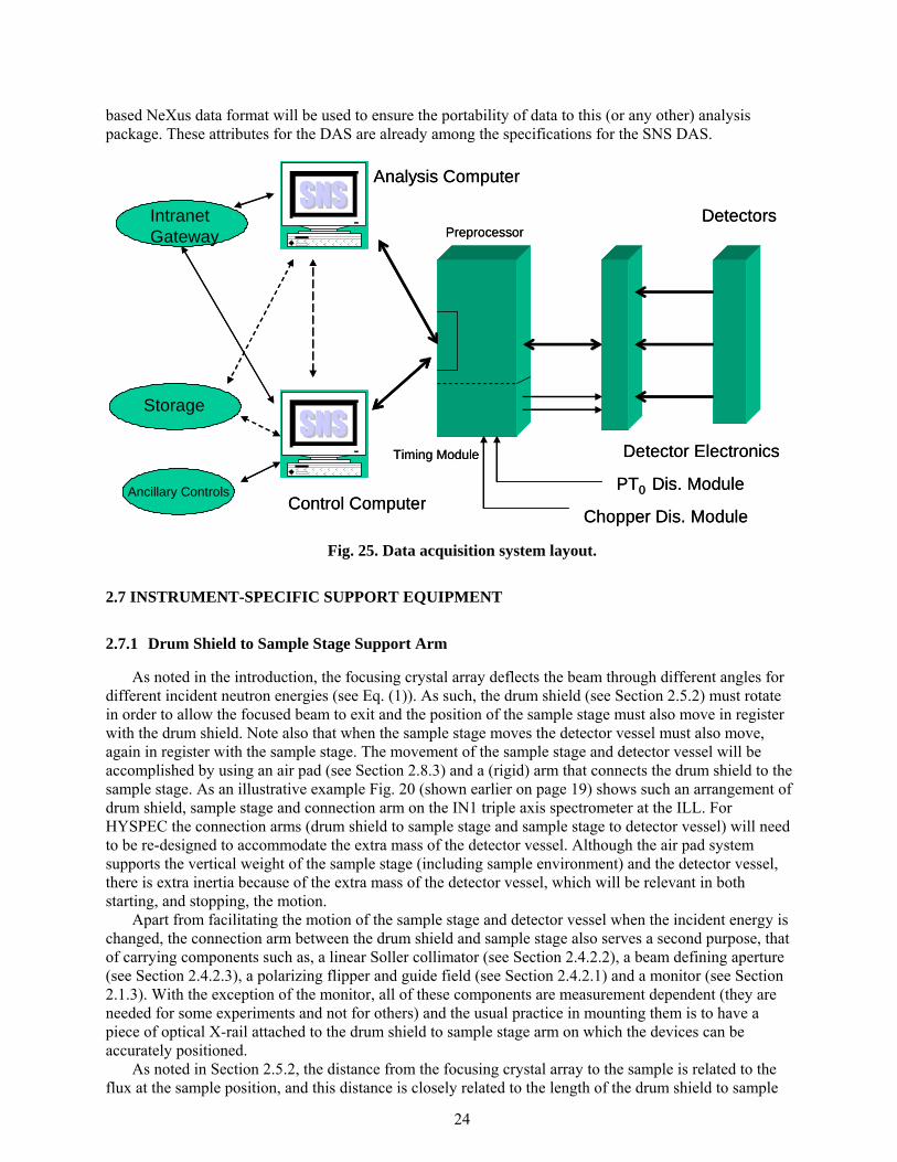
The data acquisition and analysis systems will be built from commodity components following the standards developed at SNS [25]. A main control computer will control several other subsystems, as indicated in Fig. 25. The main subsystem is the data acquisition system (DAS), where the analog signal of a neutron interacting with He3 is converted to a time- and position-stamped digital representation of that count. Furthermore, the control computer receives the proton on target signal from the accelerator information system to sync the timing of HYSPEC with the accelerator. This syncing is important for the control of the choppers as described in Sections 2.3.1, 2.3.2, 2.3.3 and 2.3.4.
Secondly, there is the slow controls subsystem, which controls ancillary computers. These ancillary controls are a chopper control computer, a sample environment computer, and one additional computer for other subsystems. Though the chopper control parameters are passed over this slow link, the phase information from the accelerator is passed over the fast link.
The data collected by the control computer will be written to a redundant array of inexpensive drives (RAID), which can also be read by an analysis computer. All of these systems will be behind an instrument-level firewall for security purposes. Password-based security for a web-based control interface, specific to each experiment, will ensure safe and secure remote operation. Only systems that can be modified without compromising safe operation will be remotely controllable, although all relevant machine parameters will be viewable. The detector signals will be digitized on the 8-packs and these digital signals will be transmitted to the control computer via preprocessor boards.
The software running on the control computer will follow the SNS standard and is being developed by the SNS DAS team. This software will acquire the data, reduce it, and allow primitive visualization. For complete analysis of a user’s data and through a collaboration with the ARCS team, the SNS is developing a software architecture for inelastic spectrometers. The HYSPEC team will develop specific packages, within this architecture and the standards set by the SNS, to meet its unique needs. The user interface to the DAS will be through a web browser, decoupling the location and operating system of the spectrometer from those of the user. For data storage, the emerging Hierarchical Data Format (HDF)-
Beam stop
24
based NeXus data format will be used to ensure the portability of data to this (or any other) analysis package. These attributes for the DAS are already among the specifications for the SNS DAS.
Preprocessor
Detector Electronics
Detectors
Storage
PT0 Dis. Module
Chopper Dis. Module
IntranetGateway
Ancillary Controls
Timing Module
Analysis Computer
Control Computer
Preprocessor
Detector Electronics
Detectors
Storage
PT0 Dis. Module
Chopper Dis. Module
IntranetGateway
Ancillary Controls
Timing Module
Analysis Computer
Control Computer
Fig. 25. Data acquisition system layout.
2.7 INSTRUMENT-SPECIFIC SUPPORT EQUIPMENT
2.7.1 Drum Shield to Sample Stage Support Arm
As noted in the introduction, the focusing crystal array deflects the beam through different angles for different incident neutron energies (see Eq. (1)). As such, the drum shield (see Section 2.5.2) must rotate in order to allow the focused beam to exit and the position of the sample stage must also move in register with the drum shield. Note also that when the sample stage moves the detector vessel must also move, again in register with the sample stage. The movement of the sample stage and detector vessel will be accomplished by using an air pad (see Section 2.8.3) and a (rigid) arm that connects the drum shield to the sample stage. As an illustrative example Fig. 20 (shown earlier on page 19) shows such an arrangement of drum shield, sample stage and connection arm on the IN1 triple axis spectrometer at the ILL. For HYSPEC the connection arms (drum shield to sample stage and sample stage to detector vessel) will need to be re-designed to accommodate the extra mass of the detector vessel. Although the air pad system supports the vertical weight of the sample stage (including sample environment) and the detector vessel, there is extra inertia because of the extra mass of the detector vessel, which will be relevant in both starting, and stopping, the motion.
Apart from facilitating the motion of the sample stage and detector vessel when the incident energy is changed, the connection arm between the drum shield and sample stage also serves a second purpose, that of carrying components such as, a linear Soller collimator (see Section 2.4.2.2), a beam defining aperture (see Section 2.4.2.3), a polarizing flipper and guide field (see Section 2.4.2.1) and a monitor (see Section 2.1.3). With the exception of the monitor, all of these components are measurement dependent (they are needed for some experiments and not for others) and the usual practice in mounting them is to have a piece of optical X-rail attached to the drum shield to sample stage arm on which the devices can be accurately positioned.
As noted in Section 2.5.2, the distance from the focusing crystal array to the sample is related to the flux at the sample position, and this distance is closely related to the length of the drum shield to sample
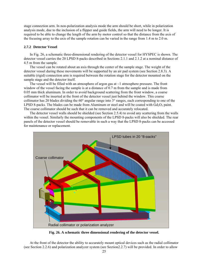
25
stage connection arm. In non-polarization analysis mode the arm should be short, while in polarization analysis mode, due to the inclusion of a flipper and guide fields, the arm will need to be longer. It is required to be able to change the length of the arm by motor control so that the distance from the axis of the focusing array to the axis of the sample rotation can be varied in the range from 1.4 m to 2.0 m. 2.7.2 Detector Vessel
In Fig. 26, a schematic three-dimensional rendering of the detector vessel for HYSPEC is shown. The detector vessel carries the 20 LPSD 8-packs described in Sections 2.1.1 and 2.1.2 at a nominal distance of 4.5 m from the sample.
The vessel can be rotated about an axis through the center of the sample stage. The weight of the detector vessel during these movements will be supported by an air pad system (see Section 2.8.3). A suitable (rigid) connection arm is required between the rotation stage for the detector mounted on the sample stage and the detector itself.
The vessel will be filled with an atmosphere of argon gas at ~1 atmosphere pressure. The front window of the vessel facing the sample is at a distance of 0.7 m from the sample and is made from 0.05 mm thick aluminum. In order to avoid background scattering from the front window, a coarse collimator will be inserted at the front of the detector vessel just behind the window. This coarse collimator has 20 blades dividing the 60° angular range into 3° ranges, each corresponding to one of the LPSD 8-packs. The blades can be made from Aluminum or steel and will be coated with Gd2O3 paint. The coarse collimator should be such that it can be removed and accurately relocated.
The detector vessel walls should be shielded (see Section 2.5.4) to avoid any scattering from the walls within the vessel. Similarly the mounting components of the LPSD 8-packs will also be shielded. The rear panels of the detector vessel should be removable in such a way that the LPSD 8-packs can be accessed for maintenance or replacement.
Fig. 26. A schematic three dimensional rendering of the detector vessel.
At the front of the detector the ability to accurately mount optical devices such as the radial collimator
(see Section 2.2.6) and polarization analyzer system (see Section2.2.7) will be provided. In order to allow
Coarse collimator
Radial collimator or polarization analyzer
LPSD tubes in 20 “8-packs”
26
for the use on HYSPEC of the SNS compensated cryomagnet, which has a diameter of ~1 m, the front edge of the mounting and optical devices should be outside a radial distance from the sample of 0.55 m.
The detector vessel, support structures and optical devices should be made from non-magnetic materials in order to allow for the possible use of un-compensated cryomagnets on HYSPEC.
2.7.3 Motor Drive System
The overall HYSPEC spectrometer contains a number of, motor controlled, moving parts. Specifically these are:
• The rotation and tilt angles (goniometer) for the focusing crystal arrays. • The vertical and horizontal focusing mechanisms for the focusing crystal arrays. • The rotation angle for the drum shield. • The (optional) aperture defining the beam size at the sample (see Section 1.1.1). • The rotation and tilt angles (goniometer) for the sample. • The rotation angle for the detector vessel. • The rotation motors on the supermirror polarization analyzer (see Section 2.2.7).
All of these motions will require both, the appropriate stepper (or DC) motor, and encoder(s) to ensure accurate and precise motion. The angles should be known to within ±0.01°.
The stepper (or DC) motors will require a motor control system to drive the motors at the appropriate speeds for accurate and precise motion. Such a system will require a “tuning” of the motion during the installation period. The motor control system will also need to interface to the instrument control computer, in order to receive positioning instructions.
2.7.4 Instrument Control Computer
In order to control the instrument a computer capable of carrying out the relevant communication to the data acquisition system, the chopper control systems, the motor control and sample environment control systems is required. Also an appropriate data analysis computer, a printer and networking equipment (for user laptops) will be needed.
2.7.5 Control Cabin
The control cabin for HYSPEC will be an enclosed structure that will house all of the primary operating computers and equipment for the instrument. The cabin will be a self-contained unit with electrical; data and communications; and heating, ventilating, and air conditioning services according to SNS standards [26]. The cabin will be a modification of an off-the-shelf structure, and will conform to all applicable codes and regulations. The location of the control cabin will depend upon the design of the external building (see Section 2.8.5). It is preferable to locate the cabin inside the external building, however if there is insufficient space it could be located outside (adjacent to) the external building.
2.7.6 Furniture
The furniture for HYSPEC will be used to populate the control cabin and the sample environment area with generally available work surfaces, seating, and storage components to support the users and instrument scientists.

27
2.8 INSTRUMENT INFRASTRUCTURE
2.8.1 Incident Beam Line Vacuum
To maintain vacuum conditions as clean as possible, dry pump systems will be used.
• In order to achieve a windowless system through the guides and choppers, these pumps will be required to maintain a vacuum that is appropriate for the operation of the choppers. If necessary, the choppers can be water cooled in order to relax the requirements on the vacuum system.
• The system will allow the vacuum in each guide section to be coupled to or isolated from other guide sections. Each section must be able to be decoupled to test for leaks in a specific section. It should be possible to isolate Boxes A and B from the rest of the guide system (see Section 6.1.2). The mechanism for isolating (and coupling) the vacuum in different sections will be remotely controlled using gate valves.
• The guide system needs to be coupled to allow for continued operation in case one of the vacuum pumps is out for service.
This system will also provide vacuum for the chopper equipment, including roughing pumps and turbo pumps for each chopper.
2.8.2 Detector Vessel Argon Gas System
As noted in Section 2.7.2 the detector vessel for HYSPEC will contain an argon gas at ~1 atmosphere pressure. A system to fill and empty the vessel of the argon gas is required. The cubic capacity of the vessel is currently estimated at 12.7 m3.
2.8.3 Air Pad System
The motion of the sample stage (Section 2.4.1) and detector vessel (Section 2.7.2) when the drum shield rotates will be achieved by using the established technique of air pads. The system works as follows. Before the motion starts the air pad system is activated and the sample and detector stages are lifted above the floor level. After the sample and detector stages have been successfully raised from the floor, the motion begins, and the sample stage and detector vessel float across the floor surface on the air pads. When the sample and detector stages reach their new position the air is turned off and they descend to the floor. The speed of motion of the sample stage and detector vessel across the floor does not need to be rapid. To move from one angular extreme (15°) to the other extreme (90°) a time of 2 minutes or less would be sufficient.
2.8.4 Sample Area Exclusion Zone and Interlocks
When the drum shield shutter (see Section 2.5.2) is open, the region around the drum shield, sample stage and detector vessel will be an exclusion zone where personnel are not permitted. This zone will be surrounded by a shielding wall of concrete blocks with a labyrinth entrance that is interlocked. A wall constructed from 300 mm thick concrete blocks should be sufficient for the purpose.
It should not be possible to open the shutter until the appropriate clearing and interlocking of the exclusion zone has taken place. Furthermore, if the interlock on the entrance to the exclusion zone should be tripped then the shutter should immediately close.
2.8.5 External Building
The location of the HYSPEC experimental area outside of the SNS Target Building requires the construction of an external building adjacent to the SNS Target Building. The utilities and services required for the construction and operation of the HYSPEC experimental area must therefore be provided by connection to the utilities/services provided for the SNS Target Building. The foundations of the

28
building should be such that they will ensure stability against settling of the building with respect to the SNS Target Building.
Inside the external building an overhead crane will be required for the construction and operation of the HYSPEC beamline. This crane must be capable of lifting the largest component beamline component in the external building.
The level of the floor inside the external building will need to be raised with respect to the level of the floor in the SNS Target Building (see Fig. 23 for an illustration). This floor should be capable of sustaining (at least locally) the heaviest beamline components, the drum shield and the shielding around the guide and Box B. The region around the drum shield, sample stage, and detector vessel will be an exclusion zone (see Section 2.8.4) and consequently a shielding wall around this area will need to be constructed inside the external building.
The control cabin for HYSPEC (see Section 2.7.5) can be accommodated in one of two ways; it can be included inside the external building or as an external building itself, adjacent to the HYSPEC building. If the latter is the case, then the control cabin should have doorway access to the HYSPEC external building. As well as the instrument control cabin, general space will be required in the external building for the storage of equipment off the beamline and outside of the exclusion zone.
Access to the HYSPEC building will need to be provided from the SNS Target Building, both at the mezzanine level and at ground floor levels. This access is required for the transport of irradiated samples and sample environment equipment to the relevant repositories inside the SNS Target Building. Both of these access doors will need to be interlocked to the Personnel Protection System (PPS). During the construction phase, access from outside of the building will be required in order to bring in large components (e.g., the drum shield).
2.8.6 Personnel Protection System
The Personnel Protection System (PPS) provides interlocks to prevent radiation exposure to personnel that would exceed regulatory requirements. The envisioned system includes an interlock on the entrance to the sample exclusion zone, such that personnel cannot enter the zone unless the secondary and drum shield shutters are closed. 2.8.7 Utilities
Several different utility services will be required by HYSPEC. These utilities include water, electricity, data, and communication lines. The electrical requirements are the same as is standard for SNS instruments. These and other services will be supplied by the Target Building general utilities [27], with tie-ins provided by the HYSPEC project.
29
3. SYSTEM INTERFACES
The HYSPEC instrument will have physical and functional interfaces with several systems associated
with the SNS, as listed subsequently. General information about the hardware that forms the physical interface, and the parameters that define the functional interface between HYSPEC and these systems, are contained in SNS Interface Control Documents, 107000000-IC0001 [26] and 100000000-IC0001 [27].
All of the interfaces will be verified with the interface control documentation and the latest geometric models of the physical components.
3.1 PHYSICAL
3.1.1 SNS Target Systems
HYSPEC will interface with SNS Target Systems components in several areas:
• Core vessel and core vessel mounting flange • Shutter assembly cavity and drive system • Outer guide rail • Interstitial shielding • Target liner flange
As soon as the above components are installed and measured, the definitions of these physical interfaces will be updated in the HYSPEC models.
3.1.2 SNS Instrument Systems
HYSPEC will interface with SNS Instrument Systems components as follows:
• Beam line 14A – CVI, Primary shutter, Beam line shielding, external building. As noted in Section 2.2.1 the CVI for beam lines 14A and 14B has been designed to allow a full size beam to be extracted for beam line 14A in the future. A similar criterion applies to the shutter and bulk shield liner. The HYSPEC shielding will be designed so that it can be integrated with beam line shielding for 14A at a future date. The design of the external building for HYSPEC will not block the possible extraction of beam line 14A out from the SNS Target Building.
• Beam line 15 – Shielding. The shielding of beam line 15 crosses the bisector between beam lines 14B and 15. The design of the shielding for these beam lines must be coordinated.
• Beam lines 13 and 15 – Magnetic field “interference.” An analysis of the possible effect on beam lines 13 and 15 of interference from magnetic fields generated at the sample position on HYSPEC by use of the SNS cryomagnets, has been carried out [27] by Dr. W.T. Lee, SNS Magnetic Field Coordinator. All of the compensated SNS cryomagnets can be run at full field without causing interference. Of the two 10T uncompensated SNS cryomagnets, one can be operated up to 9T and the other up to 2T without causing interference. These cryomagnets will not be operated above these fields on HYSPEC.
• Instrument standardized components; such as sample mounting, data acquisition, choppers, and detectors.
• Instrument Systems space allocation requirements.
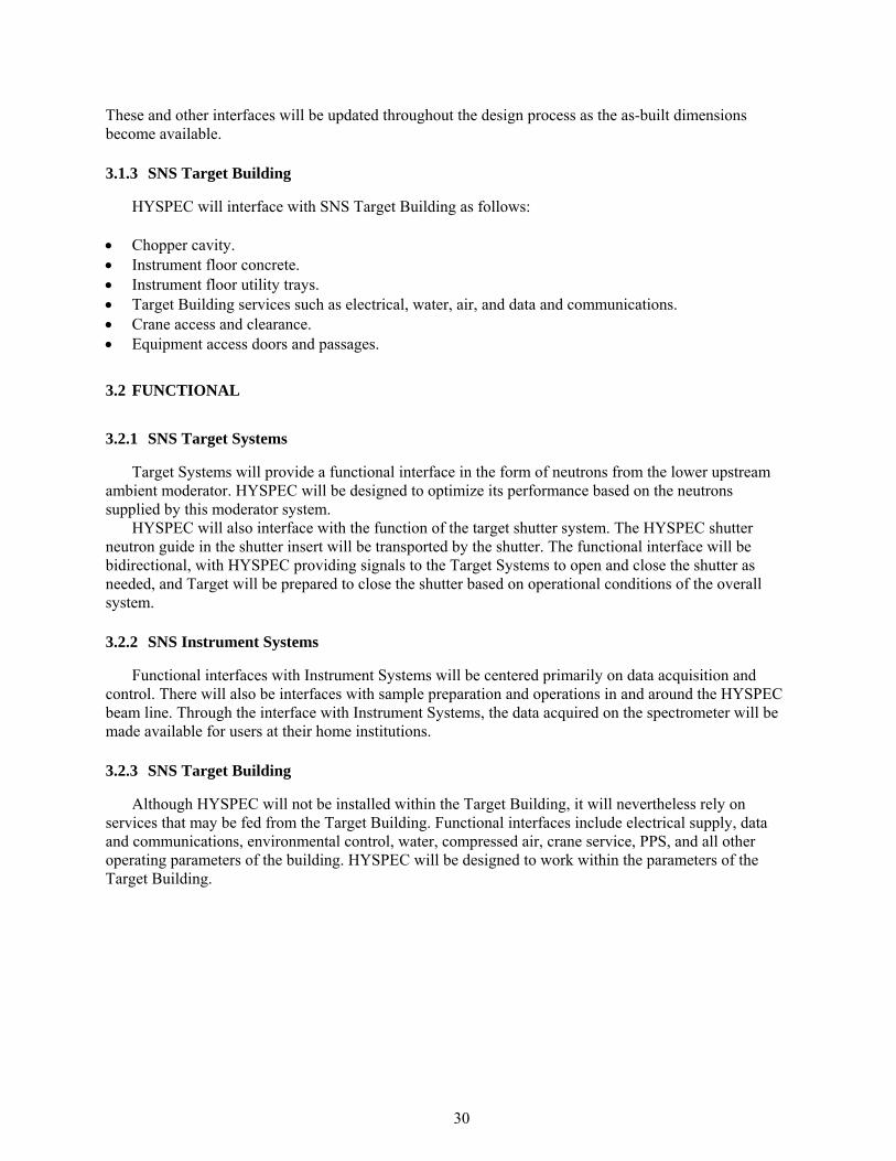
30
These and other interfaces will be updated throughout the design process as the as-built dimensions become available.
3.1.3 SNS Target Building
HYSPEC will interface with SNS Target Building as follows:
• Chopper cavity. • Instrument floor concrete. • Instrument floor utility trays. • Target Building services such as electrical, water, air, and data and communications. • Crane access and clearance. • Equipment access doors and passages.
3.2 FUNCTIONAL
3.2.1 SNS Target Systems
Target Systems will provide a functional interface in the form of neutrons from the lower upstream ambient moderator. HYSPEC will be designed to optimize its performance based on the neutrons supplied by this moderator system.
HYSPEC will also interface with the function of the target shutter system. The HYSPEC shutter neutron guide in the shutter insert will be transported by the shutter. The functional interface will be bidirectional, with HYSPEC providing signals to the Target Systems to open and close the shutter as needed, and Target will be prepared to close the shutter based on operational conditions of the overall system.
3.2.2 SNS Instrument Systems
Functional interfaces with Instrument Systems will be centered primarily on data acquisition and control. There will also be interfaces with sample preparation and operations in and around the HYSPEC beam line. Through the interface with Instrument Systems, the data acquired on the spectrometer will be made available for users at their home institutions.
3.2.3 SNS Target Building
Although HYSPEC will not be installed within the Target Building, it will nevertheless rely on services that may be fed from the Target Building. Functional interfaces include electrical supply, data and communications, environmental control, water, compressed air, crane service, PPS, and all other operating parameters of the building. HYSPEC will be designed to work within the parameters of the Target Building.

31
4. SAFETY REQUIREMENTS
4.1 SAFETY FUNCTIONS
The primary safety function of HYSPEC is to provide shielding to reduce personnel exposure to radiation. The primary safety significant components include the following:
• Core vessel insert front window, and parts of the insert that hold the window and/or serve as part of the core vessel pressure boundary and the neutron shutter position indication [both items are designated as credited engineering controls in the Spallation Neutron Source Safety Assessment Document For Neutron Facilities (SAD)] [29].
4.2 GENERAL SAFETY REQUIREMENTS
Because of the radioactive nuclide inventory in the target mercury, defense in depth will be applied to HYSPEC as needed to ensure that SAD requirements are met and to ensure the highest practicable evel of worker safety.
Ongoing safety studies will be monitored to identify all new requirements and the system will be designed to be in full compliance with the SAD. The following sections contain the requirements directly applicable to HYSPEC. The requirements for other systems that work in conjunction with HYSPEC to provide the required defense in depth are located in the SAD and the Design Criteria Document for those respective systems.
4.3 SAFETY IMPORTANCE CLASSIFICATION AND NATURAL PHENOMENOM HAZARDS (NPH) PERFORMANCE CLASSIFICATION
HYSPEC assembly structures, systems, and components (SSCs) shall meet applicable seismic requirements specified in SNS 102030100-ES0004-R00, SNS Seismic Basis of Design, Volume I: Target Facility and Equipment.
4.4 SAFETY DESIGN LIMITS
The SNS project has developed the shielding policy and has conducted shielding design in accordance with this policy. For example, the SNS design guideline for accessible shield faces in continuously occupied areas is a radiation level <0.25 mrem/h (Section 7.8 of the SAD).
4.5 SAFETY DESIGN BASIS CONDITIONS
Requirements for the safety-related inner neutron beam windows are given by SAD in Section 5.2.8. No special design basis conditions involving HYSPEC have been identified other than the general requirement that failure of a HYSPEC SSC shall not cause failure of the safety-related neutron beam window or the safety-related neutron shutter position indicators.
4.6 SAFETY PERFORMANCE PARAMETERS
Requirements for inner neutron beam windows are given by SAD in Section 5.2.8.

32
4.7 RELIABILITY REQUIREMENTS
The instrument PPS, like the balance of the PPS, follows ISA-S84.01-1996, as explained in the SNS Safety Assessment Document for Proton Facilities [15]. ISA-S84.01 includes reliability requirements commensurate to the hazard controlled by the safety-instrumented system (the PPS in this case). The relevant requirements for the Instrument PPS will be determined by the HYSPEC hazard analysis. The reliability requirement will depend on potential radiation dose rate inside the instrument cave.
4.8 SAFETY-SPECIFIC INSTRUMENTATION AND MONITORING REQUIREMENTS
There are no credited engineering controls or monitoring functions identified for HYSPEC, except the shutter position indication devices, which are part of the safety-related accelerator PPS.
4.9 OCCUPATIONAL SAFETY REQUIREMENTS
All designs shall conform to the requirements of the Occupational Safety and Health Standards, 29 CFR 1910[30]. HYSPEC shall be designed, constructed, and operated in a manner to protect the safety of workers, the public, and the environment. This shall be accomplished in compliance with the SNS Environment, Safety, and Health (ES&H) Plan [31]. The ES&H Plan includes the following elements:
• Adhering to U.S. Department of Energy (DOE) Policy 450.4, Safety Management System. • Adhering to Oak Ridge National Laboratory (ORNL) work smart standards (WSS). • Implementing radiation protection in accordance with 10 CFR 835, “Occupational Radiation
Protection.” [32] • Implementing shielding requirements. • Controlling hazards by eliminating them whenever practical. • Following industry consensus standards, unless a good reason not to has been approved. • Implementing construction safety programs to ensure worker safety during construction and testing. • Incorporating energy conservation features required by 10 CFR 435 with guidance from NSNS/97-6. • Performing independent design review on SSCs designated as credited engineering controls in the
SAD. • Implementing hazard identification and control.
4.10 ENVIRONMENTAL REQUIREMENTS
HYSPEC shall be designed, constructed, and operated in such a manner to protect the safety of workers, the public, and the environment. This shall be accomplished in compliance with the SNS Environment, Safety, and Health (ES&H) Plan [30].

33
5. QUALITY ASSURANCE REQUIREMENTS
All activities associated with HYSPEC will be conducted in accordance with the requirements
contained in SNS SINGPRJ-20-QA0001-R00 [33] and with accepted engineering standards and practices. Good engineering practices imbedded within the established design process will ensure safe and reliable operation of the instrument and will mitigate conditions that pose a threat to success. In all cases, consensus standards will be used to accomplish design activities. Where standards do not exist to adequately control an activity, appropriate administrative controls will be considered and created if required.
Thoughtfully derived and properly “graded” controls for design, manufacturing, installation, testing, and operation of HYSPEC will be established before execution of each of these activities. Additional controls will only be proposed in cases where they enhance the probability of success.
Successful quality assurance program performance will be verified through validation activities such as design reviews, surveillance activities, inspections, tests, and readiness reviews. A list of drawings will be developed during detailed design.

34
6. OPERATIONS AND MAINTENANCE REQUIREMENTS
6.1 OPERATING MODES
6.1.1 Normal Operation
In HYSPECs normal operating state the shutter will be open and the T0, T1A, and T1B choppers will be phased to permit the desired energy band of neutrons to pass and to inhibit neutrons from the prompt pulse. The neutron guide tube will be evacuated, and the T1 Fermi chopper will be phased to permit the transmission of neutrons of the desired energy. Furthermore, the speed of the T2 Fermi chopper will be set to provide the desired energy resolution. Neutron detection events will be recorded using the DAS. The events will be stored on a RAID accessible to both a data analysis computer and the control computer. The data will also be accessible by the user from his or her home institution via a conduit through an instrument- and SNS-level firewall.
6.1.2 Abnormal Operation
In the rare event that certain subsystems fail on the instrument, it can still be operated in a safe manner until maintenance operations can be performed. If the T0 and/or T1A choppers fail in an open position, the instrument can still be operated, albeit with an enhanced background. The instrument can also operate without the vacuum system for the guide sections of the incident beam line, as long as a suitable vacuum can be achieved in Box A and Box B for the choppers to run (see Section 2.8.1 in relation to the requirement that different sections of the vacuum system can be isolated). There will be a significant loss in signal if a vacuum cannot be achieved in the guide sections, but the instrument will remain operable.
If there should be a problem with the argon gas handling system for the detector vessel it is possible to operate with air in the vessel. In this case, the signal will be reduced and the background enhanced but the instrument remains operable.
The instrument can operate with a reduced number of operating detector banks, assuming there are enough available for the user to complete the necessary measurements. The counting function of the instrument will not depend on operation of the ancillary and analysis computers. Therefore, an abnormal mode where data are collected but not viewable until maintenance is performed is also envisioned.
If the motor control of the drum shield and focusing crystal arrays should fail then, if they should fail in positions where the angles of the drum shield and crystal array are in register then the instrument will remain operable, albeit at a fixed incident energy. If the angles should not be in register will each other the instrument will not be operable until they are repaired.
If the vacuum for Box B could not be achieved or the choppers T1B and T2 failed then the instrument will be not be operable until they are repaired.
6.1.3 Maintenance Operations
HYSPEC components requiring scheduled maintenance shall be designed to be replaceable within a standard shutdown period.
6.2 RELIABILITY, AVAILABILITY, AND MAINTAINABILITY REQUIREMENTS
The HYSPEC instrument will join the suite of neutron scattering instruments operated by the SNS. Engineering, fabrication, and installation of the HYSPEC instrument will follow the Quality Assurance procedures that have been developed by the SNS Experimental Facilities Division. Failure of any portion of the HYSPEC instrument system, other than the Safety Significant inner window on the core vessel insert, will not affect the continued operation of the SNS facility or any other SNS instruments. Because of its safety function, the inner window on the core vessel insert has been designed, analyzed, fabricated, and inspected to standards that ensure high reliability.

35
Other HYSPEC instrument components shall be designed with the appropriate combination of high-reliability components, redundancy, and maintenance accessibility. Beamline components that will require maintenance with regular frequency are T0 and Fermi-choppers. The HYSPEC instrument will be designed to facilitate removal of equipment that will require regular maintenance such as the T0 chopper and Fermi-Choppers. The maintenance frequency is expected to be approximately once every four years for the T0 chopper and once every two years for the Fermi- choppers. The reliability of the entire T0 chopper system including the rotor assemblies, bearings, drive motors, and drive motor control system shall be such that it can operate continuously at rated speed for at least 24 months between maintenance periods. The reliability of the entire Fermi-chopper system including the rotor assemblies, bearings, drive motors, and drive motor control system shall be such that it can operate continuously at rated speed for at least 24 months between maintenance periods. HYSPEC will require the sellers to provide a listing of components subject to wear and/or performance degradation along with a mean-time-between-failures (MTBF) for each type of chopper. In addition, a apare parts list shall be provided. The window thickness for the choppers shall be minimized to provide optimal neutron transmission while being consistent with standard vacuum practice and operating safety requirements. HYSPEC will include design features in the components and shielding to ensure easy accessibility and maintainabuility of the equipment that requires regular maintenance or with limited lifetime.
6.3 REMOTE MAINTENANCE
HYSPEC will be designed to minimize the need for remote installation and removal. Accommodations will be made in the design of components that are in areas of potentially high residual radiation.
6.4 GENERAL MAINTENANCE
HYSPEC will be designed for maintenance operations within a reasonable amount of shutdown time. Component access and handling will be addressed in the design.
6.5 ABNORMAL EVENTS AND RECOVERY PROCEDURES
Consequences of identified, credible off-normal events shall be identified during detail design. Recovery procedures and features to permit recovery shall be defined for each identified event.

36
7. INSTALLATION REQUIREMENTS
Installation requirements will be addressed in the detailed design phase. For HYSPEC components within the Target Building access to the 30-ton crane and the 7½ -ton Javelin crane will be factored into the detailed design of componets, especially shielding sections. For HYSPEC components in the external building, the availability of a 10-ton crane (see Section 2.8.5) will be factored into the detailed design of components.
Building size and access requirements will be considered for large components, such as the detector vacuum vessel. Further installation requirements for HYSPEC will be established during detail design.

37
8. INTEGRATED SYSTEM TESTING REQUIREMENTS
After completion of installation and before commissioning with the neutron beam, a series of tests
will be performed on HYSPEC to ensure and demonstrate its readiness for operation. These tests will include checking that the chopper system can be appropriately phased by the chopper control computer, that the control computer is talking to the preprocessors, that the control computer can control all of the ancillary control computers, and that all the computers can be accesed through the instrument-level firewall following the appropriate security procedures. In addition, all of the safety systems will be tested in an integrated fashion. The integrated system testing will be varified by an instrument readiness review that will indicate that the instrument is ready for beam and can move onto comissioning. Completion of the integrated system testing and the readiness review constitute project completion (CD-4) for HYSPEC within the SING MIE project.

38
9. COMMISSIONING PLANS
Although commissioning with beam and operation are not part of the HYSPEC scope under the SING project, this subject is briefly discussed in the following.
Commissioning will provide an opportunity to tune the instrument for optimal performance. Commissioning will involve several parts. A vanadium standard sample will be used to characterize the relative sensitivity of the detectors and to optimize the various chopper configurations. Several standard samples will be used to further characterize the performance of the instrument at various values of energy transfer and count rate. A few standard single crystals will be used to test the operation of the goniometer. Many of the samples will be provided by the instrument development team members. Commissioning will also involve iteratively adding shielding near the detector to reduce background.

39
10. CODES AND STANDARDS
Design will be performed in accordance with ORNL WSS. In addition, nationally recognized codes will be employed wherever necessary.
Pressure-containing components shall be designed and fabricated per the intent of the American Society of Mechanical Engineers (ASME) Boiler & Pressure Vessel Code, Section VIII, or the ASME Code for Pressure Piping (ASME B31.1) [34], as applicable. Vacuum vessels will be designed per applicable vacuum vessel standards. The applicable codes for other aspects of the design will be determined during detail design and will be specific to the component to which they are applied. The codes will be contained in the specifications and drawings used for procurement, fabrication, testing, and installation of system components. It is anticipated that standard codes can be used in the following areas:
• Materials specifications (with modifications as required for special service conditions). • Welding and welding inspection codes. • Others—TBD.
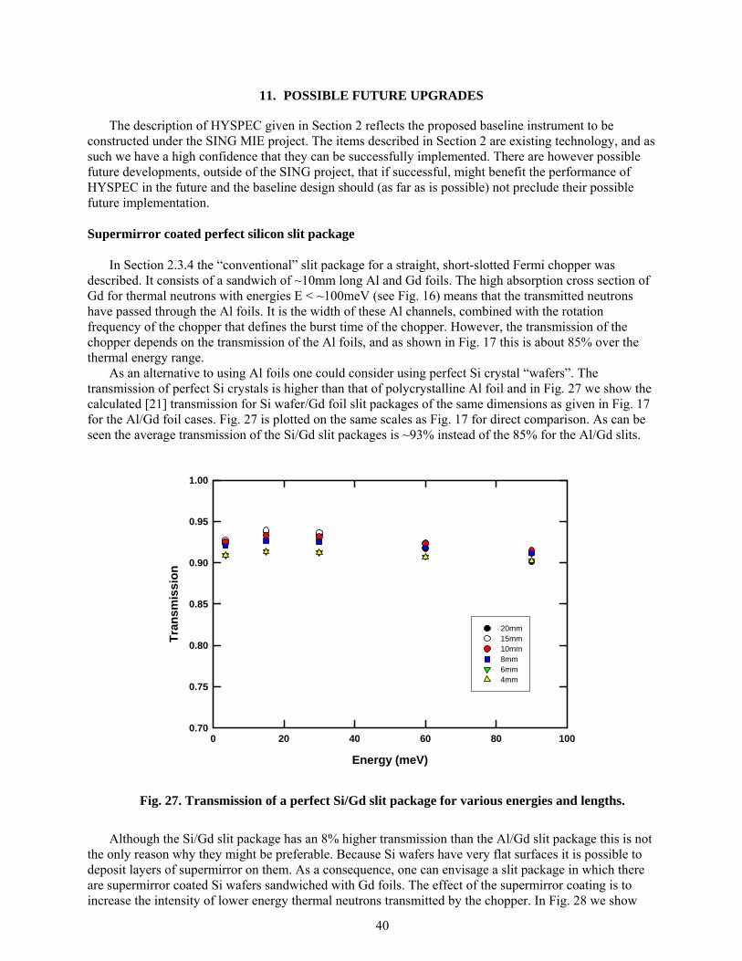
40
11. POSSIBLE FUTURE UPGRADES
The description of HYSPEC given in Section 2 reflects the proposed baseline instrument to be constructed under the SING MIE project. The items described in Section 2 are existing technology, and as such we have a high confidence that they can be successfully implemented. There are however possible future developments, outside of the SING project, that if successful, might benefit the performance of HYSPEC in the future and the baseline design should (as far as is possible) not preclude their possible future implementation.
Supermirror coated perfect silicon slit package
In Section 2.3.4 the “conventional” slit package for a straight, short-slotted Fermi chopper was described. It consists of a sandwich of ~10mm long Al and Gd foils. The high absorption cross section of Gd for thermal neutrons with energies E < ~100meV (see Fig. 16) means that the transmitted neutrons have passed through the Al foils. It is the width of these Al channels, combined with the rotation frequency of the chopper that defines the burst time of the chopper. However, the transmission of the chopper depends on the transmission of the Al foils, and as shown in Fig. 17 this is about 85% over the thermal energy range.
As an alternative to using Al foils one could consider using perfect Si crystal “wafers”. The transmission of perfect Si crystals is higher than that of polycrystalline Al foil and in Fig. 27 we show the calculated [21] transmission for Si wafer/Gd foil slit packages of the same dimensions as given in Fig. 17 for the Al/Gd foil cases. Fig. 27 is plotted on the same scales as Fig. 17 for direct comparison. As can be seen the average transmission of the Si/Gd slit packages is ~93% instead of the 85% for the Al/Gd slits.
Energy (meV)
0 20 40 60 80 100
Tran
smis
sion
0.70
0.75
0.80
0.85
0.90
0.95
1.00
20mm15mm10mm8mm6mm4mm
Fig. 27. Transmission of a perfect Si/Gd slit package for various energies and lengths.
Although the Si/Gd slit package has an 8% higher transmission than the Al/Gd slit package this is not
the only reason why they might be preferable. Because Si wafers have very flat surfaces it is possible to deposit layers of supermirror on them. As a consequence, one can envisage a slit package in which there are supermirror coated Si wafers sandwiched with Gd foils. The effect of the supermirror coating is to increase the intensity of lower energy thermal neutrons transmitted by the chopper. In Fig. 28 we show
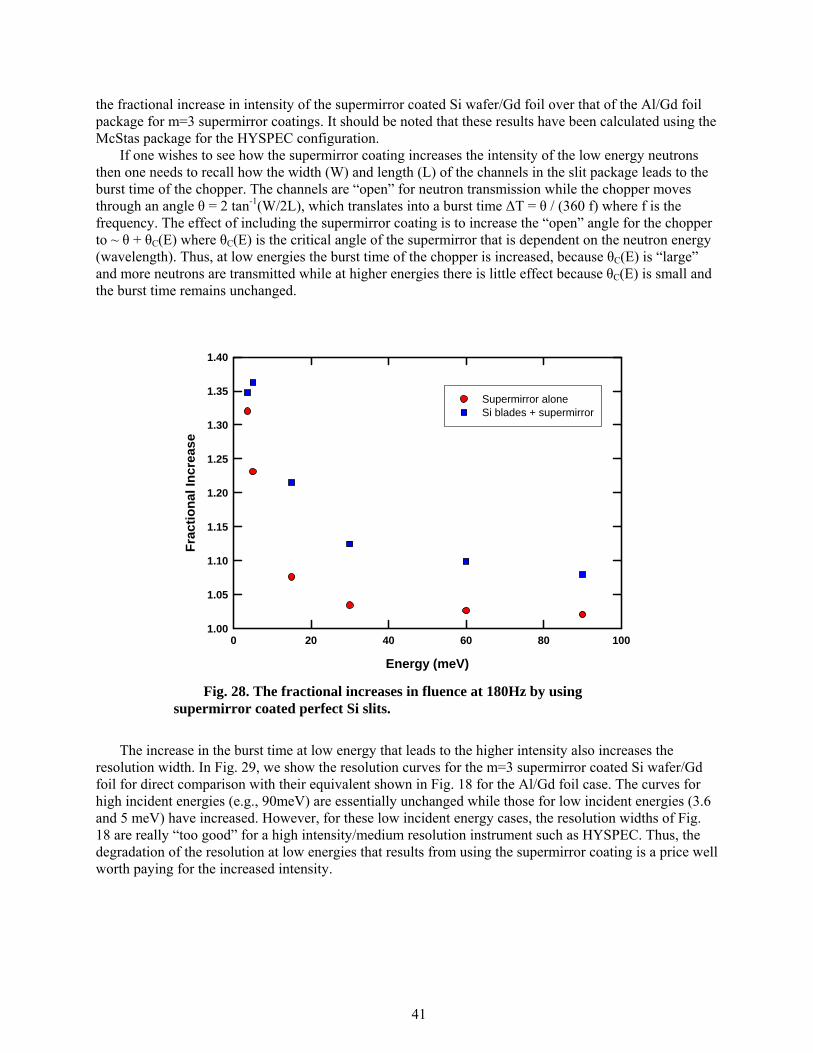
41
the fractional increase in intensity of the supermirror coated Si wafer/Gd foil over that of the Al/Gd foil package for m=3 supermirror coatings. It should be noted that these results have been calculated using the McStas package for the HYSPEC configuration.
If one wishes to see how the supermirror coating increases the intensity of the low energy neutrons then one needs to recall how the width (W) and length (L) of the channels in the slit package leads to the burst time of the chopper. The channels are “open” for neutron transmission while the chopper moves through an angle θ = 2 tan-1(W/2L), which translates into a burst time ∆T = θ / (360 f) where f is the frequency. The effect of including the supermirror coating is to increase the “open” angle for the chopper to ~ θ + θC(E) where θC(E) is the critical angle of the supermirror that is dependent on the neutron energy (wavelength). Thus, at low energies the burst time of the chopper is increased, because θC(E) is “large” and more neutrons are transmitted while at higher energies there is little effect because θC(E) is small and the burst time remains unchanged.
Energy (meV)
0 20 40 60 80 100
Frac
tiona
l Inc
reas
e
1.00
1.05
1.10
1.15
1.20
1.25
1.30
1.35
1.40
Supermirror aloneSi blades + supermirror
Fig. 28. The fractional increases in fluence at 180Hz by using
supermirror coated perfect Si slits.
The increase in the burst time at low energy that leads to the higher intensity also increases the
resolution width. In Fig. 29, we show the resolution curves for the m=3 supermirror coated Si wafer/Gd foil for direct comparison with their equivalent shown in Fig. 18 for the Al/Gd foil case. The curves for high incident energies (e.g., 90meV) are essentially unchanged while those for low incident energies (3.6 and 5 meV) have increased. However, for these low incident energy cases, the resolution widths of Fig. 18 are really “too good” for a high intensity/medium resolution instrument such as HYSPEC. Thus, the degradation of the resolution at low energies that results from using the supermirror coating is a price well worth paying for the increased intensity.
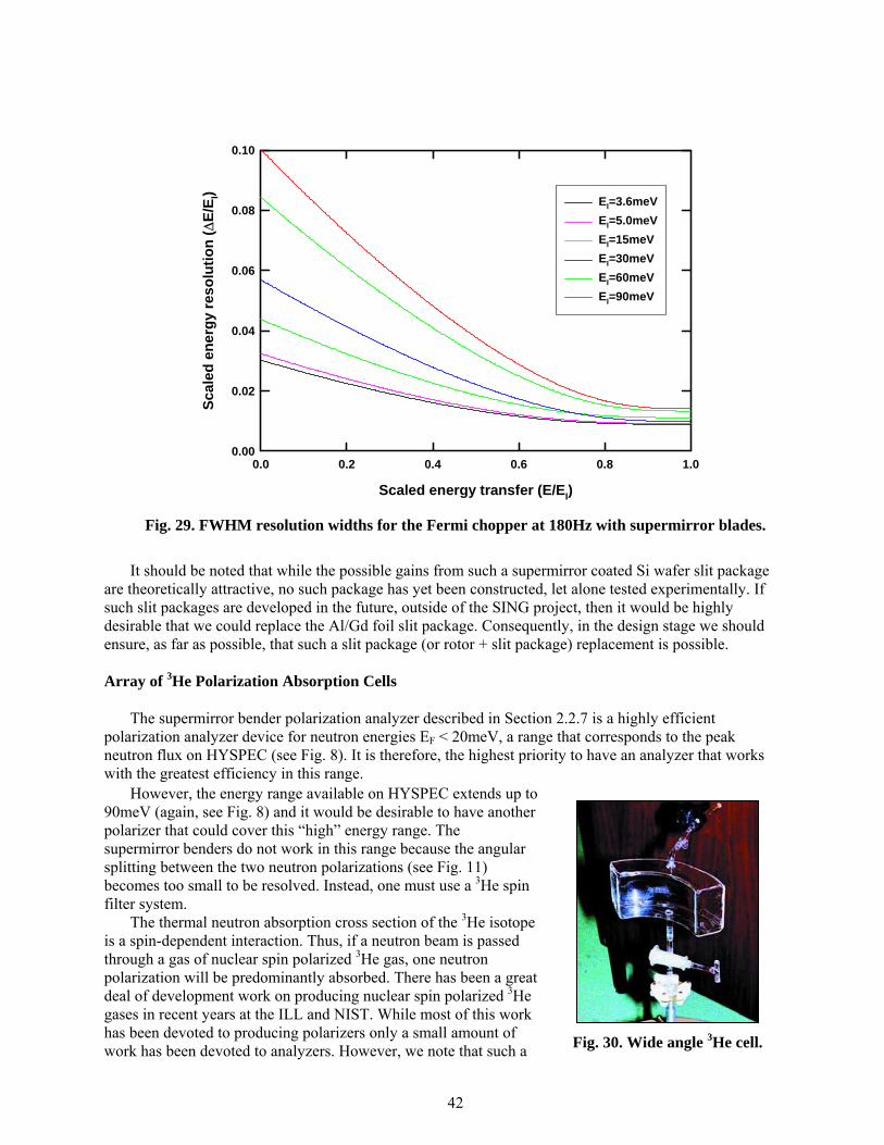
42
Scaled energy transfer (E/EI)
0.0 0.2 0.4 0.6 0.8 1.0
Scal
ed e
nerg
y re
solu
tion
( ∆E/
E I)
0.00
0.02
0.04
0.06
0.08
0.10
EI=3.6meVEI=5.0meVEI=15meVEI=30meVEI=60meVEI=90meV
Fig. 29. FWHM resolution widths for the Fermi chopper at 180Hz with supermirror blades.
It should be noted that while the possible gains from such a supermirror coated Si wafer slit package
are theoretically attractive, no such package has yet been constructed, let alone tested experimentally. If such slit packages are developed in the future, outside of the SING project, then it would be highly desirable that we could replace the Al/Gd foil slit package. Consequently, in the design stage we should ensure, as far as possible, that such a slit package (or rotor + slit package) replacement is possible.
Array of 3He Polarization Absorption Cells
The supermirror bender polarization analyzer described in Section 2.2.7 is a highly efficient
polarization analyzer device for neutron energies EF < 20meV, a range that corresponds to the peak neutron flux on HYSPEC (see Fig. 8). It is therefore, the highest priority to have an analyzer that works with the greatest efficiency in this range.
However, the energy range available on HYSPEC extends up to 90meV (again, see Fig. 8) and it would be desirable to have another polarizer that could cover this “high” energy range. The supermirror benders do not work in this range because the angular splitting between the two neutron polarizations (see Fig. 11) becomes too small to be resolved. Instead, one must use a 3He spin filter system.
The thermal neutron absorption cross section of the 3He isotope is a spin-dependent interaction. Thus, if a neutron beam is passed through a gas of nuclear spin polarized 3He gas, one neutron polarization will be predominantly absorbed. There has been a great deal of development work on producing nuclear spin polarized 3He gases in recent years at the ILL and NIST. While most of this work has been devoted to producing polarizers only a small amount of work has been devoted to analyzers. However, we note that such a
Fig. 30. Wide angle 3He cell.
43
3He device was used by Stewart et al. in a powder diffraction experiment on D1B at the ILL [35]. The cell used in this experiment is shown in Fig. 30. The design shown in Fig. 30 would not be directly applicable to the situation on HYSPEC. Instead, a design involving an array of 10 cells of 40mm2 area by 120mm long placed in front of the detector vessel would be more appropriate [36]. If these cells are filled with 3He gas up to 2atm then they can perform polarization analysis up to 90meV.
However, it should be noted that each of these cells will require its own “holding” magnetic field to maintain the nuclear spin polarization of the 3He gas and a mu-metal shield to protect against stray external magnetic fields. The length of such shield is ~300mm. A conceptual design for such a device for HYSPEC has been outlined by Passell, Hagen, and Lee [36]. While such a 3He gas cell polarization analyzer is able to analyze the neutron polarization over a relatively wide range of final neutron energies (~5meV up to 90meV) calculations of the solid angle it will cover show that it is much smaller than that of the supermirror bender described in Section 2.2.7.
However, such a device would allow HYSPEC to access a wider energy range and as a future upgrade, allow some experiments that are not possible with the supermirror polarization analyzer to be performed.

44
REFERENCES
[1] HYSPEC: A Crystal Time of Flight Spectrometer for the Spallation Neutron Source, S. Shapiro and I. Zaliznyak, BNL Report 52677 (December 2002)
[2] Project Execution Plan for the SNS Instruments – Next Generation (SING) Project, SNS SINGPRJ-10-PN0004-R01, UT-Battelle, LLC, Oak Ridge Natl. Lab, Oak Ridge, TN (April 2005).
[3] Equipment Specification Linear Position Sensitive Detector, Experimental Facilities Instrument Systems Shared Design/Activity Detectors WBS 1.7.3.3, SNS-107030300-EQ0002-R00, R.G. Cooper and P.R. Summers (December 2004)
[4] Private communication (e-mail) from R. Cooper, head of SNS detector group (August, 2005)
[5] Evaluation of Reuter Stokes Linear Position Sensitive Detectors for the ARCS Instrument, SNS-DRAFT
[6] Design Criteria Document for the High Resolution Chopper Spectrometer (SEQUOIA), SNS SING17-00-DC0001-R01, G. Granroth and D. Vandergriff, (October 2004)
[7] Private communication, R.K. Crawford.
[8] Internal Dimensions of the Core Vessel Insert for Beamlines 14A and 14B, HYSPEC Technical Note 0008, V.J. Ghosh (January 2005)
[9] SNS Drawing # SING-14B-20M8U8714A-050, January 2005
[10] Spallation Neutron Source Interface Control Document 1.6 Target Systems and 1.7 – Instrument Systems, SNS 100000000-IC0001, UT-Battelle, LLC, Oak Ridge Natl. Lab, Oak Ridge, TN (May 2003)
[11] User and Programmers Guide to the Neutron Ray-Tracing Package McStas, Version 1.8, P. Willendrup, E. Farhi, K. Lefmann, P. Olaf-Astrand, M. Hagen and K. Nielsen, Riso National Laboratory report Riso-R-1416(EN), (May 2004)
[12] McStas Simulations for Guide Configuration Optimization, HYPSEC Technical Note 0009, V.J. Ghosh (February 2005)
[13] Description of the Proposed Neutron Guides for HYSPEC, HYSPEC Technical Note 0002, V.J. Ghosh and M. Hagen, (January 2005)
[14] Talk presented at HYSPEC IDT Meeting September 10th 2004 by V.J. Ghosh. (See talks on website http://neutrons.phy.bnl.gov/CNS/hyspec/index.htm)
[15] Spallation Neutron Source Safety Assessment Document for Proton Facilities, SNS 102030103 ES0018-R00, Spallation Neutron Source Project Office, Oak Ridge, Tennessee, June 2005.
[16] McStas Results for the HYSPEC Focusing Crystals, HYSPEC Technical Note 0012, M. Hagen (March 2005)

45
[17] 3He Transmission Polarizer Options for HYSPEC, HYSPEC Technical Note 0006, I. Zaliznyak (October 2004)
[18] Polarized Beam Operation of the HYBRID Spectrometer at the Pulsed Spallation Neutron Source, I.Zaliznyak, V.J. Ghosh, S.M. Shapiro and L.Passell, Physica B 356, 150-155 (2005)
[19] The Proposed Choppers for HYSPEC, HYSPEC Technical Note 0001, L. Passell (October 2004)
[20] Neutron Cross Sections, BNL report 325, D.J. Hughes and J.A. Harvey (July 1955)
[21] Calculation of Slit Transmissions for a Straight Slotted Fermi Chopper, HYSPEC Technical Note 0013, L. Passell (March 2005)
[22] McStas results for the HYSPEC chopper system, HYSPEC Technical Note 0011, M. Hagen (March 2005)
[23] Review of the Shielding Designed for Various SNS Instruments with Emphasis on the use of these Studies to Develop a Starting Shielding Model for the HYSPEC Guides, HYSPEC Technical Note 0003, V.J. Ghosh and M. Hagen (October 2004)
[24] An Initial Model for the HYSPEC Shielding, HYSPEC Technical Note 0010, V.J. Ghosh and M. Hagen (March 2005)
[25] Instrument Systems Data Acquisition Design Criteria Document, IS-1.7.3.2-4034-SP-A-00, UT-Battelle, Oak Ridge Natl. Lab, Oak Ridge, TN (Dec. 20, 2000).
[26] Spallation Neutron Source Interface Control Document Interfacing WBS Elements 1.7 – Instrument Systems and 1.8 – Conventional Facilities, SNS 107000000-IC0001, UT-Battelle, LLC, Oak Ridge Natl. Lab, Oak Ridge, TN (July 2000).
[27] Spallation Neutron Source Interface Control Document Sample Environment Interface Flanges SNS 107030501-IC001-R00, UT-Battelle, Oak Ridge Natl. Lab, Oak Ridge, TN (Mar. 25, 2003).
[28] Magnetic fringe field analysis for HYSPEC, SING14B-00-CA0001-R00, Dr. W.T. Lee, UT-Battelle, LLC, Oak Ridge Natl. Lab, Oak Ridge, TN (August 2005)
[29] Spallation Neutron Source Safety Assessment Document for Neutron Facilities, SNS
102030102 ES0016-R00, Spallation Neutron Source Project Office, Oak Ridge, Tennessee, August 2005,
[30] Title 29, Part 1910, “Occupational Safety and Health Standards,” 29 CFR 1910 (Revised Feb. 2002).
[31] SNS Environment, Safety, and Health (ES&H) Plan, SNS 102030000ES0001R00, Lockheed
Martin Energy Research Corp., Oak Ridge Natl. Lab., Oak Ridge, TN (Dec. 1, 1999).
[32] Title 10, Part 835, “Occupational Radiation Protection,” 10 CFR 835, U.S. Department of Energy, Washington, D.C., December 14, 1993
[33] Spallation Neutron Source Instruments Next Generation—SING Quality Assurance Plan, SINGPRJ-20-QA0001-R00, UT-Battelle, LLC, Oak Ridge Natl. Lab, Oak Ridge, TN (March

46
2004).
[34] ASME Boiler and Pressure Vessel Code, Section VIII, American Society of Mechanical Engineers, Fairfield, N.J. (July 2001).
[35] J. R. Stewart, K. H. Andersen, H. Humblot, C. Ritter and T. Roberts, R. Cywinski, W. Heil, ILL Annual Report, http://www.ill.fr/AR-02/site/areport/fb_108.htm (2002).
[36] Private communication, L. Passell, M. Hagen and W.T. Lee (2005)