Embed Size (px)
Citation preview
Design Data 6
Loads and Supporting Strengths Elliptical and Arch Pipe
The hydraulic and structural characteristics of elliptical and arch shapes offer advantages, under certain conditions, over the circular shape commonly used for sewer and culvert pipe. For minimum cover conditions, or where vertical clearance is limited by existing structures, horizontal elliptical and arch pipe are particularly suitable since the vertical heights are less than the height of hydraulically equivalent circular sizes. Horizontal elliptical and arch pipe have greater flow capacity for the same depth of flow than most other structures of equivalent full capacity. Vertical elliptical pipe, because of its narrower span, requires less excavation for trench installations and is subjected to less backfill load. Because of the greater
Original Ground
Bd
H
height of section of vertical elliptical pipe, increased side support is realized in embankment installations and the fill load is also reduced because of the smaller span. These structural characteristics make vertical elliptical pipe particularly suitable where deep trenches or high embankment fills are necessary. In addition, the geometric properties of vertical elliptical pipe make its use advantageous where horizontal clearance is limited by existing structures. Hydraulically, vertical elliptical pipe provides higher flushing velocities under minimum flow conditions.
0 1 2 3 4 5
14
12
10
8
6
4
2
0
Values of Load Coefficient Cd
Val
ues
of
Bd
H
San
d an
d G
rave
l K
µ' =
0.1
65S
atur
ated
Top
Soi
l K
µ' =
0.1
50O
rdin
ary
Cla
y K
µ' =
0.1
30S
atur
ated
Cla
y K
µ' =
0.1
10
Figure 1 Trench Installation
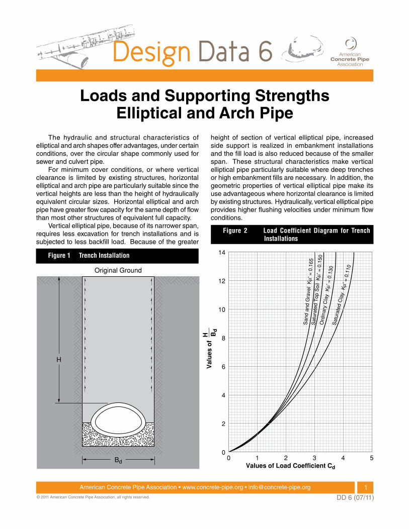
Figure 2 Load Coefficient Diagram for Trench Installations
1American Concrete Pipe Association • www.concrete-pipe.org • [email protected]
DD 6 (07/11)© 2011 American Concrete Pipe Association, all rights reserved.
Horizontal and vertical elliptical pipe represent two different products from the standpoint of structural strength, hydraulics and type of application. Arch pipe is similar to horizontal elliptical pipe in that the ratios of vertical rise to horizontal span are approximately the same for both shapes.
Design Procedure The design procedure for the selection of pipe strength requires:
1. Determination of Earth Load 2. Determination of Live Load 3. Selection of Bedding 4. Determination of Load Factor 5. Application of Factor of Safety 6. Selection of Pipe
DEtErminAtion of EArth LoAD The two most common types of installations are trench and positive projecting embankment.
trench installations Trench installations are normally used in the construction of sewers. The pipe is installed in a relatively narrow trench excavated in undisturbed soil and then covered with backfill extending to the original ground surface. When a rigid pipe is installed in a narrow trench and backfilled, the backfill material will tend to settle. As illustrated in Figure 1, this downward movement generates friction forces along the trench walls, which act upward to help support the weight of the backfill material. The magnitude of the frictional forces depends on the unit weight of the backfill material w, the value of Rankine’s lateral pressure ratio K, and the coefficient of sliding friction µ’, between the backfill material and trench walls. The backfill load on a pipe installed in a trench condition is equal to the weight of the mass of backfill material within the trench less the summation of the frictional load transfers, and is computed by the equation:
Wd = Cd w B2d (1)
where Wd = backfill load, pounds per linear foot Cd = load coefficient for trench installations w = unit weight of backfill material, pounds per
cubic foot Bd = width of trench at the top of the pipe, feet
Figure 2 presents values of the load coefficient Cd, for various types of soils and H/Bd ratios. The H term
represents the height of backfill from the top of the pipe to the original ground surface.
Embankment installations Positive projecting embankment installations are normally used in the construction of culverts. The pipe is installed on the original ground or compacted fill and then covered by an earth fill or embankment. In considering earth loads on rigid pipe installed in a positive projecting embankment condition, it is convenient to designate the prism of fill directly above the pipe and bounded by vertical planes tangent to the sides of the pipe as the interior prism. The exterior prisms are the prisms of fill adjacent to the vertical planes on both sides of the pipe. Since the length of the exterior prisms are greater than the interior prism, the exterior prisms of fill will compress more than the interior prism as the embankment is built up. As illustrated in Figure 3, the relative settlements between the interior prism and exterior prisms generate downward frictional forces along the vertical planes adjacent to the sides of the pipe. The fill load on a pipe installed in a positive projecting embankment condition is equal to the weight of the prism of fill over the pipe plus the summation of the downward frictional forces, and is computed by the equation:
Wc = Cc w B 2c (2)
Interior Prism
Plane of Equal Settlement
Top of Embankment
Exterior Prism
BeforeLoading
AfterLoading
Exterior Prism
Bc
Figure 3 Embankment Installation
2American Concrete Pipe Association • www.concrete-pipe.org • [email protected]
DD 6 (07/11)© 2011 American Concrete Pipe Association, all rights reserved.
0 2 4 6 8 10 12 14 16 18 20
14
12
10
8
6
4
2
0
Values of Load Coefficient CC
Val
ues
of
BC
H
Complete Condition
Incomplete C
ondition
r sdp =
0
0.1
0.3
0.5
1.0
2.0
Kµ = 0.19
0 2 4 6 8 10 12 14 16 18 20
14
12
10
8
6
4
2
0
Values of Load Coefficient CC
Val
ues
of
BC
H
Complete Condition
Incomplete C
ondition
r sdp =
0
0.1
0.3
0.5
1.0
2.0
Kµ = 0.19
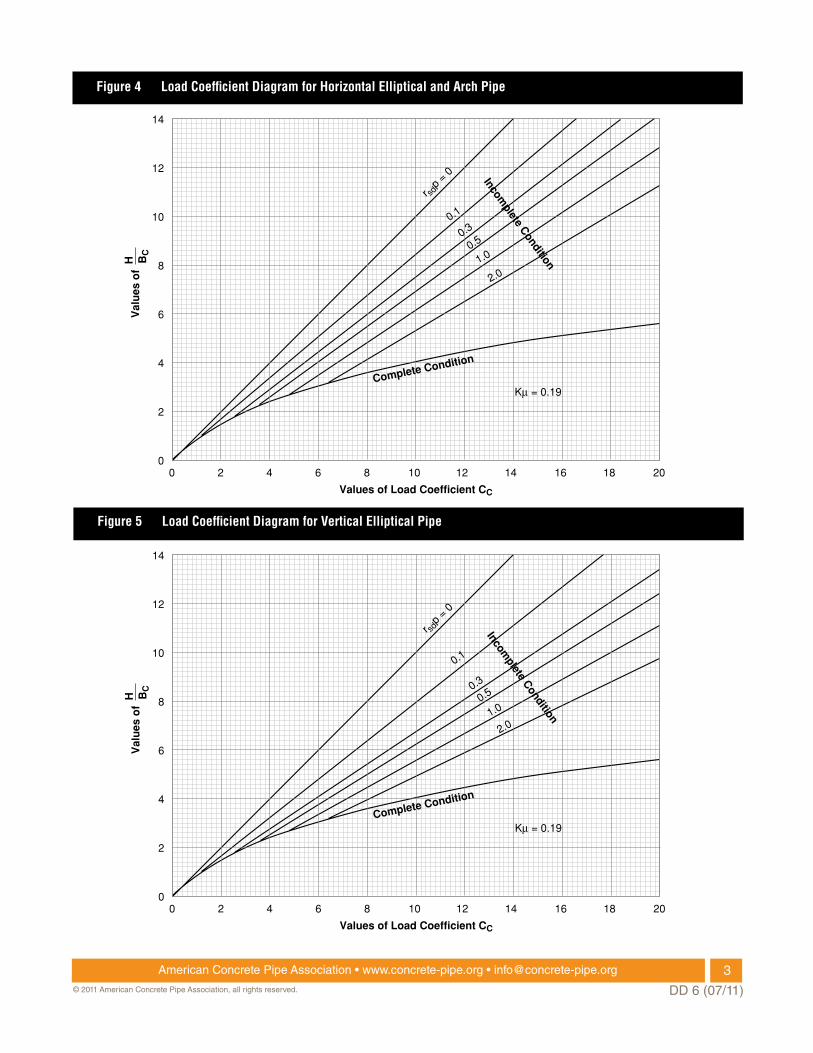
Figure 4 Load Coefficient Diagram for Horizontal Elliptical and Arch Pipe
Figure 5 Load Coefficient Diagram for Vertical Elliptical Pipe
3American Concrete Pipe Association • www.concrete-pipe.org • [email protected]
DD 6 (07/11)© 2011 American Concrete Pipe Association, all rights reserved.
where Wc = fill load, pounds per linear foot Cc = load coefficient for positive projecting
embankment installations w = unit weight of fill material, pounds per cubic
foot Bc = outside horizontal span of the pipe, feet
Figure 4 presents values of the load coefficient Cc for horizontal elliptical pipe and arch pipe and Figure 5 presents values of the load coefficient Cc for vertical elliptical pipe. In Figures 4 and 5, load coefficient values are presented for various H/Bc ratios and values of rsdp. The H term represents the height of fill above the top of the pipe. The rsd term represents the settlement ratio which evaluates the magnitude of the relative settlements, including the settlement of the original ground and the deflection of the pipe. Recommended design values of the settlement ratio are listed in Table 1. The p term represents the projection ratio which is defined as the vertical distance the pipe projects above the original ground divided by the outside vertical height* of the pipe. As indicated in Figures 4 and 5, the load coefficient is dependent on the product of the settlement ratio and the projection ratio rsdp.
* The projection ratio is defined differently from circular pipe (circular pipe based on horizontal diameter). The difference arises from the inequality of vertical height to horizontal width for elliptical and arch pipe.
Depending on the height of fill H, outside horizontal span of the pipe Bc, and the product of the settlement ratio and projection ratio rsdp, the downward frictional forces may or may not act throughout the entire height of fill. If the frictional forces act throughout the entire fill height, this condition is classified as the ComPLETE ConDITIon and is represented by the curved line in Figures 4 and 5. Under the complete condition unequal settlements will occur at the fill surface. If the frictional forces do not act throughout the entire fill height, this condition is classified as the InComPLETE ConDITIon and is represented by the straight rsdp lines in Figures 4 and 5.
transition Width When a pipe is installed in a trench condition the backfill load is a function of the trench width, as given
by equation (1). For any given size of pipe, type of soil and height of backfill, as the trench width is increased a limiting width is reached beyond which the trench width no longer affects the load. The trench width at which this condition occurs is defined as the TRAnSITIon WIDTH. At the transition width the load on the pipe is a maximum and remains constant. This maximum load is given by the embankment equation (2). Therefore, backfill loads for trench installations should be computed by the trench equation (1) for all trench width which give a load equal to or less than the maximum load computed by the embankment equation (2). maximum loads as computed from equation (2) will usually result in trench installations involving shallow cover or large trench widths relative to the size of the pipe under consideration.
DEtErminAtion of LivE LoAD In the selection of pipe to be installed under shallow cover, it is necessary to evaluate the effect of live loads. Live load considerations are usually necessary in the design of pipe installed with shallow cover under railroads, airports and unsurfaced highways. Complete discussions and design procedures for the determination of live load are presented in Design Data 1.
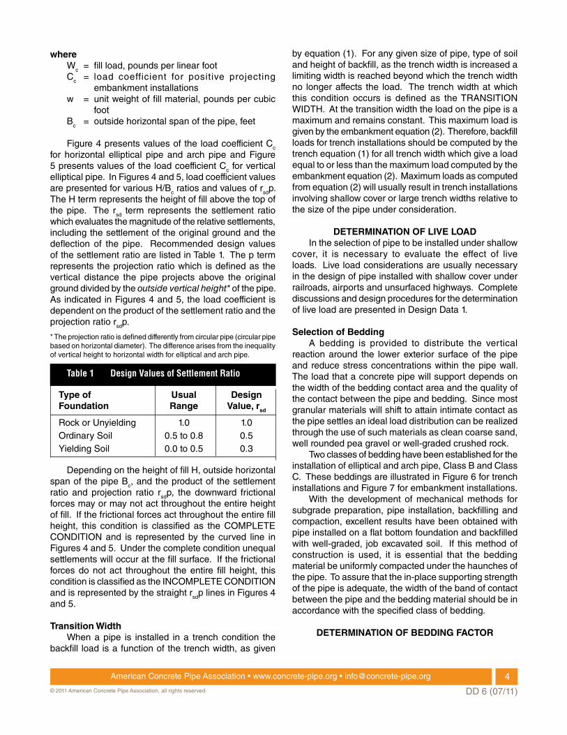
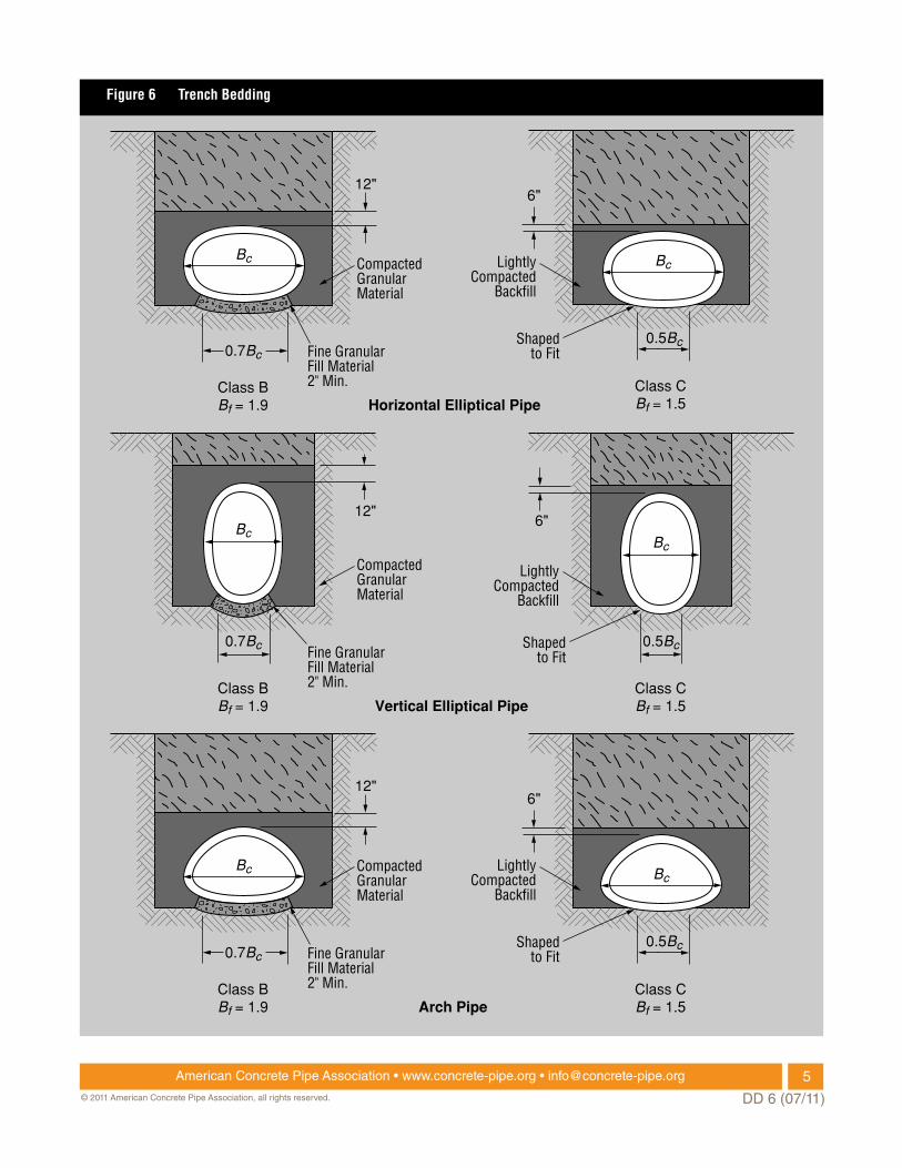
Selection of Bedding A bedding is provided to distribute the vertical reaction around the lower exterior surface of the pipe and reduce stress concentrations within the pipe wall. The load that a concrete pipe will support depends on the width of the bedding contact area and the quality of the contact between the pipe and bedding. Since most granular materials will shift to attain intimate contact as the pipe settles an ideal load distribution can be realized through the use of such materials as clean coarse sand, well rounded pea gravel or well-graded crushed rock. Two classes of bedding have been established for the installation of elliptical and arch pipe, Class B and Class C. These beddings are illustrated in Figure 6 for trench installations and Figure 7 for embankment installations. With the development of mechanical methods for subgrade preparation, pipe installation, backfilling and compaction, excellent results have been obtained with pipe installed on a flat bottom foundation and backfilled with well-graded, job excavated soil. If this method of construction is used, it is essential that the bedding material be uniformly compacted under the haunches of the pipe. To assure that the in-place supporting strength of the pipe is adequate, the width of the band of contact between the pipe and the bedding material should be in accordance with the specified class of bedding.
DEtErminAtion of BEDDing fActor
type of Usual Design foundation range value, rsd
Rock or Unyielding 1.0 1.0 ordinary Soil 0.5 to 0.8 0.5 Yielding Soil 0.0 to 0.5 0.3
Table 1 Design Values of Settlement Ratio
4American Concrete Pipe Association • www.concrete-pipe.org • [email protected]
DD 6 (07/11)© 2011 American Concrete Pipe Association, all rights reserved.
Arch Pipe
Vertical Elliptical Pipe
Horizontal Elliptical Pipe
Class BBf = 1.9
Bc
12"
CompactedGranularMaterial
Fine GranularFill Material 2" Min.
0.7Bc
Class BBf = 1.9
Bc Bc
12"
CompactedGranularMaterial
Fine GranularFill Material 2" Min.
0.7Bc
Class BBf = 1.9
Bc
12"
CompactedGranularMaterial
Fine GranularFill Material 2" Min.
0.7Bc
Class CBf = 1.5
Bc
0.5Bc
Class CBf = 1.5
Bc
6"
LightlyCompacted
Backfill
Shaped to Fit
0.5Bc
Class CBf = 1.5
6"
LightlyCompacted
Backfill
Shaped to Fit
6"
LightlyCompacted
Backfill
Shaped to Fit
0.5Bc
Figure 6 Trench Bedding
5American Concrete Pipe Association • www.concrete-pipe.org • [email protected]
DD 6 (07/11)© 2011 American Concrete Pipe Association, all rights reserved.
Arch Pipe
Vertical Elliptical Pipe
Horizontal Elliptical Pipe
Bc
Class B
BcpB'cp max.=0.7
B'c
H
Fine Granular FillMaterial 2" Min.
Compacted Soil
0.1B'c0.3B'c
Class B
pB'cp max.=0.7
B'c
H
Fine Granular FillMaterial 2" Min.
Compacted Soil
0.1B'c0.3B'c
Class B
pB'cp max.=0.7
B'c
H
Fine Granular FillMaterial 2" Min.
Compacted Soil
0.1B'c0.3B'c
Class C
BcpB'cB'c
H
0.1B'c
Shaped to Fit
Class C
pB'cB'c
H
0.1B'c
Shaped to Fit
Class C
pB'cB'c
H
0.1B'cShaped to Fit
Bc Bc
Bc
Figure 7 Embankment Bedding
6American Concrete Pipe Association • www.concrete-pipe.org • [email protected]
DD 6 (07/11)© 2011 American Concrete Pipe Association, all rights reserved.
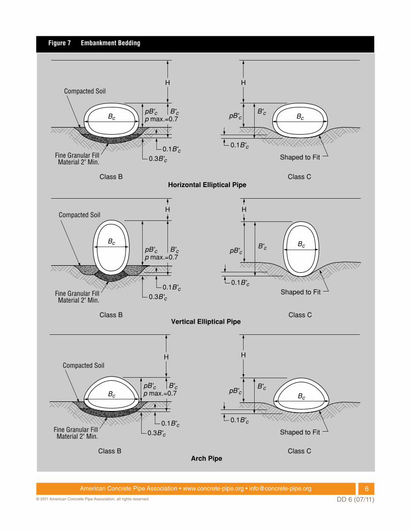
A common method to determine the inherent strength of pipe is to conduct a three-edge bearing test. The three-edge bearing test is the most severe loading to which any pipe will be subjected, since a concentrated load is imposed at the top of the pipe and the reaction is along two narrow surfaces at the bottom of the pipe. Under installed conditions the vertical load is distributed over the width of the pipe and the reaction is distributed in accordance with the type of bedding. A comparison of three-edge bearing forces and the distribution of external forces under installed conditions is illustrated in Figure
8. The bedding factor Bf, is the ratio of the strength of a pipe under installed conditions of loading and bedding to the strength of the pipe in the three-edge bearing test.
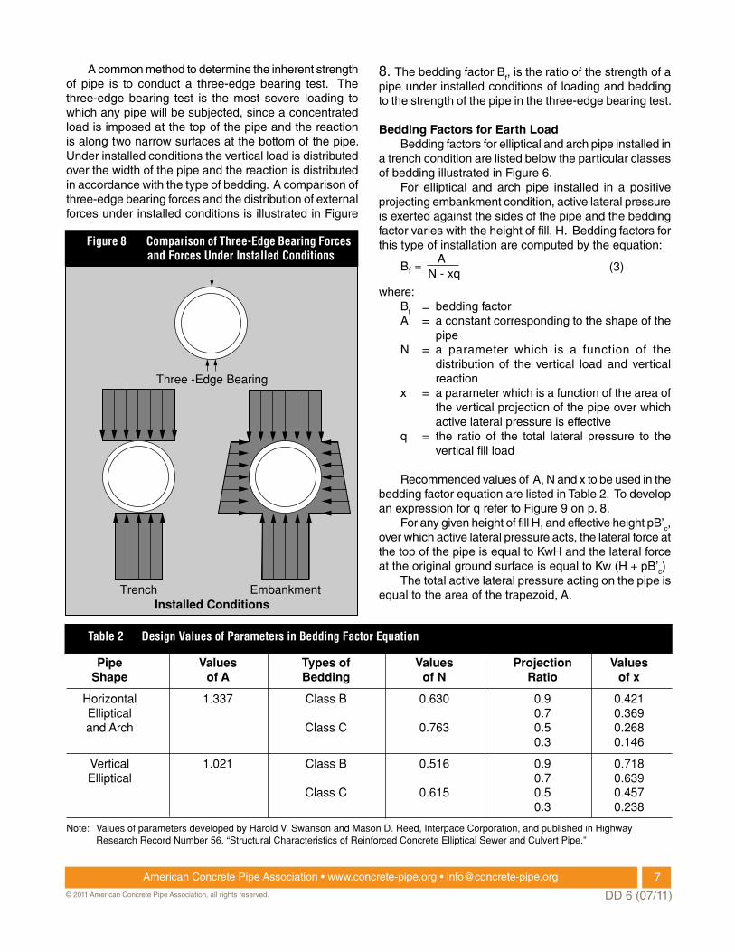
Bedding factors for Earth Load Bedding factors for elliptical and arch pipe installed in a trench condition are listed below the particular classes of bedding illustrated in Figure 6. For elliptical and arch pipe installed in a positive projecting embankment condition, active lateral pressure is exerted against the sides of the pipe and the bedding factor varies with the height of fill, H. Bedding factors for this type of installation are computed by the equation:
Bf = N - xq
A(3)
where: Bf = bedding factor A = a constant corresponding to the shape of the
pipe n = a parameter which is a function of the
distribution of the vertical load and vertical reaction
x = a parameter which is a function of the area of the vertical projection of the pipe over which active lateral pressure is effective
q = the ratio of the total lateral pressure to the vertical fill load
Recommended values of A, n and x to be used in the bedding factor equation are listed in Table 2. To develop an expression for q refer to Figure 9 on p. 8. For any given height of fill H, and effective height pB’c, over which active lateral pressure acts, the lateral force at the top of the pipe is equal to KwH and the lateral force at the original ground surface is equal to Kw (H + pB’c) The total active lateral pressure acting on the pipe is equal to the area of the trapezoid, A.
Three -Edge Bearing
TrenchInstalled Conditions
Embankment
Pipe Values Types of Values Projection Values Shape of A Bedding of N Ratio of x
Horizontal 1.337 Class B 0.630 0.9 0.421 Elliptical 0.7 0.369 and Arch Class C 0.763 0.5 0.268 0.3 0.146
Vertical 1.021 Class B 0.516 0.9 0.718 Elliptical 0.7 0.639 Class C 0.615 0.5 0.457 0.3 0.238
Note: Values of parameters developed by Harold V. Swanson and Mason D. Reed, Interpace Corporation, and published in Highway Research Record Number 56, “Structural Characteristics of Reinforced Concrete Elliptical Sewer and Culvert Pipe.”
Figure 8 Comparison of Three-Edge Bearing Forces and Forces Under Installed Conditions
Table 2 Design Values of Parameters in Bedding Factor Equation
7American Concrete Pipe Association • www.concrete-pipe.org • [email protected]
DD 6 (07/11)© 2011 American Concrete Pipe Association, all rights reserved.
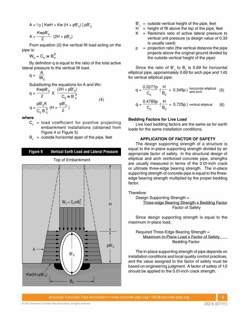
A = [ KwH + Kw (H + pB'c) ] pB'c
A = (2H + pB'c)
1/2
KwpB'c2
From equation (2) the vertical fill load acting on the pipe is:
Wc = Cc w B2c
By definition q is equal to the ratio of the total active lateral pressure to the vertical fill load.
q =
Wc
A
Substituting the equations for A and Wc:
q =
pB'c
KwpB'c2 2
c
(2H + pB'c)
Cc w B
2cCc B
X
q =pB'cK
(H + )2
(4)
where Cc = load coefficient for positive projecting
embankment installations (obtained from Figure 4 or Figure 5)
Bc = outside horizontal span of the pipe, feet
B’c = outside vertical height of the pipe, feet H = height of fill above the top of the pipe, feet K = Rankine’s ratio of active lateral pressure to
vertical unit pressure (a design value of 0.33 is usually used)
p = projection ratio (the vertical distance the pipe projects above the original ground divided by the outside vertical height of the pipe)
Since the ratio of B’c to Bc is 0.69 for horizontal elliptical pipe, approximately 0.69 for arch pipe and 1.45 for vertical elliptical pipe:
q =0.2277p
( + 0.345p )Cc
H
Bc
horizontal ellipticaland arch
q =0.4785p
( + 0.725p )Cc
H
Bcvertical elliptical
(5)
(6)
Bedding factors for Live Load Live load bedding factors are the same as for earth loads for the same installation conditions.
APPLicAtion of fActor of SAfEty The design supporting strength of a structure is equal to the in-place supporting strength divided by an appropriate factor of safety. In the structural design of elliptical and arch reinforced concrete pipe, strengths are usually measured in terms of the 0.01-inch crack or ultimate three-edge bearing strength. The in-place supporting strength of concrete pipe is equal to the three-edge bearing strength multiplied by the proper bedding factor.
Therefore: Design Supporting Strength = Three-edge Bearing Strength x Bedding Factor Factor of Safety
Since design supporting strength is equal to the maximum in-place load,
Required Three-Edge Bearing Strength = maximum In-Place Load x Factor of Safety Bedding Factor
The in-place supporting strength of pipe depends on installation conditions and local quality control practices, and the value assigned to the factor of safety must be based on engineering judgment. A factor of safety of 1.0 should be applied to the 0.01-inch crack strength.
Bc
HWc = CcwB
A
Top of Embankment
Kw(H+pB'c)
pB'c
2c
B'c
Figure 9 Vertical Earth Load and Lateral Pressure
8American Concrete Pipe Association • www.concrete-pipe.org • [email protected]
DD 6 (07/11)© 2011 American Concrete Pipe Association, all rights reserved.
Technical data herein is considered reliable, but no guarantee is made or liability assumed.
minimum D-Loads In Three-Edge Bearing TestPounds Per Linear Foot Per Foot of Inside Horizontal Span
Horizontal Elliptical Arch Vertical Elliptical 0.01” Crack Ultimate 0.01” Crack Ultimate 0.01” Crack Ultimate D0.01 Dult. D0.01 Dult. D0.01 Dult. HE-A 600 900 II 1000 1500 VE-II 1000 1500 HE-I 800 1200 III 1350 2000 VE-III 1350 2000 HE-II 1000 1500 IV 2000 3000 VE-IV 2000 3000 HE-III 1350 2000 VE-V 3000 3750 HE-IV 2000 3000 VE-VI 4000 5000A
ST
m C
507
Cla
ss
AS
Tm
C50
6 C
lass
AS
Tm
C50
7 C
lass
Selection of Pipe The American Society for Testing and materials (ASTm) has developed standard specifications for reinforced concrete elliptical culvert, storm drain and sewer pipe and reinforced concrete arch culvert, storm drain and sewer pipe. Each specification contains design criteria and tables of minimum strengths. Since numerous pipe sizes are available, three-edge bearing strengths are classified by D-loads. The D-load is the load per linear foot per foot of nominal inside horizontal span of the pipe in feet. Table 3 lists minimum 0.01-inchcrack and ultimate D-loads based on the strength classes covered by ASTm specifications for elliptical and arch pipe.
The selection of required pipe strength for elliptical and arch pipe is computed by the equation:
D-load = x F.S. (7)
WL+WE
Bf x S
where D-load = three-edge bearing test strength of pipe
expressed in pounds per linear foot per foot of nominal inside horizontal span. The three-edge bearing test strength is the test load to produce either a 0.01-inch crack (D0.01) or ultimate load (Dult.)
WL = live load WE = earth load Bf = bedding factor S = inside horizontal span of the pipe, feet F.S. = factor of safety
The following examples illustrate the design procedure for the selection of required pipe strength.
Example 1: Horizontal elliptical Pipe
given: A 38-inch x 60-inch horizontal elliptical pipe (equivalent 48-inch circular) with a 5-1/2-inch wall thickness is to be installed in a 7-foot wide trench and covered with 1.0 foot of sand and gravel backfill material weighing 110 pounds per cubic foot.
find: The required pipe strength in terms of the 0.01-inch crack D-load.
Solution: 1. Determination of Earth Load (WE). For trench installations involving shallow cover the load should be computed by both the trench equation and the embankment equation and the lesser value used. The trench backfill load is given by equation (1).
Wd = Cd w B 2d
From Figure 2, for H/Bd = 0.14 and sand and gravel backfill, the load coefficient Cd = 0.14
Bd
HBc
Table 3 Three-Edge Bearing Test Strengths
9American Concrete Pipe Association • www.concrete-pipe.org • [email protected]
DD 6 (07/11)© 2011 American Concrete Pipe Association, all rights reserved.
Wd = 0.14 x110 x (7)
Wd = 755 pounds per linear foot
2
The embankment fill load is given by equation (2).
Wc = Cc w B 2c
In evaluating the embankment fill load a settlement ratio rsd, and projection ratio p, must first be assumed. Based on an rsd
value of 0.7 and p value of 0.7, the product rsdp = 0.49.
From Figure 4, for H/Bc = 0.17 and rsdp = 0.49, the load coefficient Cc = 0.17.
Wc = 0.17 x110 x (5.92)
Wc = 652 pounds per linear foot
2
Since Wc is less than Wd, the trench width does not affect the load and the load is a maximum of 652 pounds per linear foot.
2. Determination of Live Load (WL) From Design Data 32: Highway Live Loads
on Concrete Elliptical Pipe for H = 1.0 foot, Bc = 5.92 feet, a single 16,000 pound dual wheel load on an unsurfaced roadway, 30 percent impact, the live load is 2,610 pounds per linear foot.
3. Selection of Bedding A Class C bedding will be assumed.
4. Determination of Bedding Factor (Bf) From Figure 6, for horizontal elliptical
pipe installed on a Class C bedding the bedding factor is 1.5.
5. Application of Factor of Safety (F.S.) A factor of safety of 1.0 based on the 0.01-
inch crack will be applied.
6. Selection of Pipe The D-load is given by equation (7).
D-load = x F.S.WL+WE
Bf x S
D0.01 = x 1.02,610 +652
1.5 x 5.0
Answer: D0.01 = 435 pounds per linearfoot per foot of insidehorizonal span
From Table 3, the minimum 0.1-inch crack D-load for an ASTm C507 Class HE-I pipe is 800. Therefore, a Class HE-I would be more than adequate.
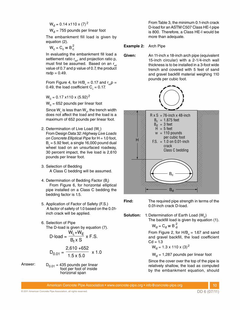
Example 2: Arch Pipe
given: An 11-inch x 18-inch arch pipe (equivalent 15-inch circular) with a 2-1/4-inch wall thickness is to be installed in a 3-foot wide trench and covered with 5 feet of sand and gravel backfill material weighing 110 pounds per cubic foot.
find: The required pipe strength in terms of the 0.01-inch crack D-load.
Solution: 1. Determination of Earth Load (WE) The backfill load is given by equation (1).
Wd = Cd w B 2d
From Figure 2, for H/Bd = 1.67 and sand and gravel backfill, the load coefficient Cd = 1.3
Wd = 1.3 x 110 x (3)
Wd = 1,287 pounds per linear foot
2
Since the cover over the top of the pipe is relatively shallow, the load as computed by the embankment equation, should
Bd
H
Bc = 1.875 feetBd = 3 feetH = 5 feetw = 110 pounds
per cubic footF.S. = 1.0 on 0.01-inch
crack Class C bedding
= 76-inch x 48-inchR x S
Bc
10American Concrete Pipe Association • www.concrete-pipe.org • [email protected]
DD 6 (07/11)© 2011 American Concrete Pipe Association, all rights reserved.
be compared with the trench load to determine if the 3-foot trench width exceeds the transition width.
The fill is given by equation (2).
Wc = Cc w B 2c
From Figure 4, for H/Bc = 2.67, an assumed rsdp = 0.5, the load coefficient Cc = 3.75.
Wc = 3.75 x 110 x (1.875)
Wc = 1,450 pounds per linear foot
2
Since Wc is larger than Wd the 3-foot trench width is less than the transition width and the load is given by the trench equation Wd = 1,287.
2. Determination of Live Load (WL) From Design Data 31: Highway Live Loads
On Concrete Arch Pipe, for H= 5 feet, Bc = 1.875 feet, alternate loading on an unsurfaced roadway, the live load is 410 pounds per linear foot.
3. Selection of Bedding A Class C bedding will be assumed for
this example.
4. Determination of Bedding Factor (Bf) From Figure 6, for each arch pipe installed
on a Class C bedding, the bedding factor is 1.5.
5. Application of Factor of Safety (F.S.) A factor of safety of 1.0 based on the 0.01-
inch crack will be applied.
6. Selection of Pipe The D-load is given by equation (7).
D-load = x F.S.WL+WE
Bf x S
D0.01 = x 1.0410 + 1287
1.5 x 1.5 Answer: D0.01 = 754 pounds per linear
foot per foot of insidehorizonal span
From Table 3, the minimum 0.01-inch crack D-load for an ASTm C506 Class II pipe is 1,000. Therefore, a Class II pipe would be more than adequate.
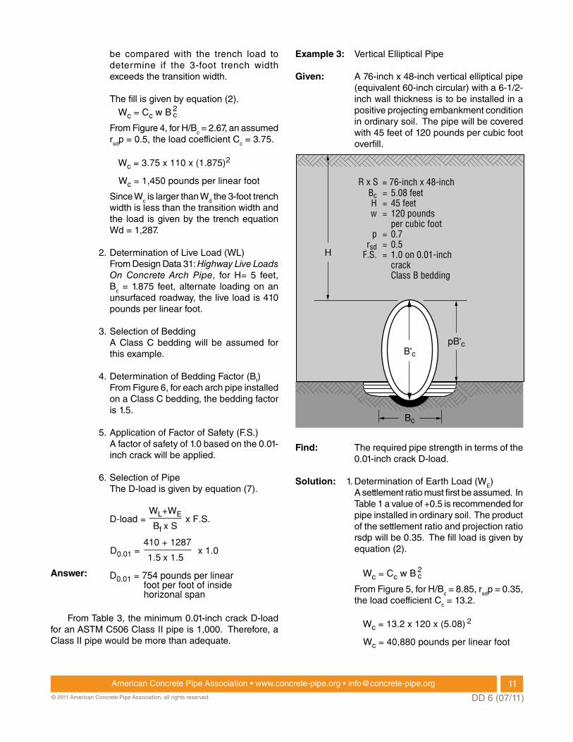
Example 3: Vertical Elliptical Pipe
given: A 76-inch x 48-inch vertical elliptical pipe (equivalent 60-inch circular) with a 6-1/2-inch wall thickness is to be installed in a positive projecting embankment condition in ordinary soil. The pipe will be covered with 45 feet of 120 pounds per cubic foot overfill.
find: The required pipe strength in terms of the 0.01-inch crack D-load.
Solution: 1. Determination of Earth Load (WE) A settlement ratio must first be assumed. In
Table 1 a value of +0.5 is recommended for pipe installed in ordinary soil. The product of the settlement ratio and projection ratio rsdp will be 0.35. The fill load is given by equation (2).
Wc = Cc w B 2c
From Figure 5, for H/Bc = 8.85, rsdp = 0.35, the load coefficient Cc = 13.2.
Wc = 13.2 x 120 x (5.08)
Wc = 40,880 pounds per linear foot
2
pB'c
Bc
H
Bc = 5.08 feetH = 45 feetw = 120 pounds
per cubic footp = 0.7
rsd = 0.5F.S. = 1.0 on 0.01-inch
crack Class B bedding
= 76-inch x 48-inchR x S
B'c
11American Concrete Pipe Association • www.concrete-pipe.org • [email protected]
DD 6 (07/11)© 2011 American Concrete Pipe Association, all rights reserved.
2. Determination of Live Load (WL) At a depth of 45 feet live load is negligible.
3. Selection of Bedding A Class B bedding with a projection ratio
of 0.7 will be assumed for this example. In actual design, it may be necessary to consider types of beddings in order to arrive at the most economical overall installation.
4. Determination of Bedding Factor (Bf) The bedding factor is given by equation
(3).
Bf = N - xq
A
From Table 2, for vertical elliptical pipe. A = 1.021, for Class B bedding n = 0.516 and for a projection ratio of 0.7 x = 0.639.
Bf = 0.516 – 0.639q
1.021
The q term in the bedding factor equation is given by equation (6).
q =0.4785p
Cc
0.4785 x 0.7
13.2
H
Bc
q =
q = 0.237
( + 0.725p )
( 8.85 + 0.725 x 0.7)
Substituting the value of q in the bedding factor equation:
Bf =
Bf = 2.80
0.516 – 0.639q x 0.2371.021
5. Application of Factor of Safety (F.S.) A factor of safety of 1.0 based on the 0.01-
inch crack will be applied.
6. Selection of Pipe The D-load is given by equation (7).
D-load = x F.S.WL+WE
WL+WE = Wc = 40,880
Bf x S
D0.01 = x 1.040,880
2.8 x 4.0
Technical data herein is considered reliable, but no guarantee is made or liability assumed.
Answer: D0.01 = 3,650 pounds per linearfoot per foot of insidehorizonal span
From Table 3, the minimum 0.01-inch crack D-load for an ASTm C507 Class VE-VI pipe is 4,000. Therefore, a Class VE-VI vertical elliptical pipe would be more than adequate.
12American Concrete Pipe Association • www.concrete-pipe.org • [email protected]
DD 6 (07/11)© 2011 American Concrete Pipe Association, all rights reserved.

![[XLS]Standard and non-standard item code table · Web view91" X 58" ELLIPTICAL PIPE 02582 91" X 58" ELLIPTICAL CONC. PIPE 02630 98" X 63" ELLIPTICAL PIPE 02632 98" X 63" ELLIPTICAL](https://img.pdfslide.net/doc/110x75/5ae3d8767f8b9a5d648e7b87/xlsstandard-and-non-standard-item-code-view91-x-58-elliptical-pipe-02582-91-x.jpg)


![[XLS] · Web view91" X 58" ELLIPTICAL PIPE 02582 91" X 58" ELLIPTICAL CONC. PIPE 02630 98" X 63" ELLIPTICAL PIPE 02632 98" X 63" ELLIPTICAL CONC. PIPE 02680 106" X 68" ELLIPTICAL](https://img.pdfslide.net/doc/110x75/5ae3d8767f8b9a5d648e7b83/xls-view91-x-58-elliptical-pipe-02582-91-x-58-elliptical-conc-pipe-02630-98-x.jpg)