Embed Size (px)
Citation preview
DESIGN, DEVELOPMENT and EVALUATION of STANFORD/AMES EVA PREHENSORS
/’
progress report for the period April, 1986 to March, 1987
submitted to:
National Aeronautics and Space Administration Ames Research Center
Moffet Field, CA 94035
[NASA-CR-181116) D E S I G N , DEVELOPMENT A N D N-7-25763 .1
EVA LU AT1 ON OF S T A N F O R D/AH ES EXTR A-VEB XLX LAB RCTIVITY (EVA) P B E H E N S O R S Progress B 3 p o r t , Apr, 1986 - Bar. 1987 [Stanford Univ,) 46 Unclas p A v a i l : EITIS HC Ao3/HF A01 ZSCL 05tf G3/54 0082687
su bmi t t ed by:
Professor Larry J. Leifer
in collaboration with: J . Jameson, M. LeBlanc, D. Wilson, E. Sabelman & D. Schwandt
Center for Design Research Stanford University
Department of Mechanical Engineering Stanford, CA 94305
’ ..+prill987 9
1
https://ntrs.nasa.gov/search.jsp?R=19870016330 2018-05-23T05:04:31+00:00Z

1 1
Design. Development and Evaluation of Stanford/Ames EVA Prehensors
SUMMARY
Space Station operations and maintenance are expected to make unprecedented demands on astronaut Extra-Vehicular Activity (EVA). With the Space Station expected to operate with a 8-10 psi atmosphere (versus 4 psi for Shuttle operations), the effectiveness of pressurized gloves is called into doubt a t the same time that EVA activity levels must be increased. To address the need for more frequent and more complex EVA missions and also to extend the dexterity, duration and safety of EVA astronauts, NASA-Ames Research Center and Stanford University have an ongoing cooperative agreement to explore and compare alternative solutions. Nearing completion toward this objective is the initial development of a series of Stanford/Ames manually-powered EVA Prehensors.
Each prehensor consists of a shroud forming a pressure enclosure around the astronaut’s hand, and a linkage system to transfer the motions and forces of the hand to mechanical digits connected to the shroud. Three different prehensors are currently under development, each representing an increasing degree of complexity: the “l-DOF” or “Prosthetic Prehensor” having a detachable two- or three-fingered end-effector is intended to establish criteria for mechanical simplicity, compactness, comfort and ease of training by which more capable devices can be measured. The “2-DOF” or “Multi-Grasp Prehensor” has a fixed thumb plus two fingers capable of pinching against each other and against the thumb independently; a second thumb can potentially be added to perform specialized tasks. The more versatile “6-DOF” or “Direct-Link Prehensor” having three articulated fingers permits all six basic forms of grasp, in particular, finger-tip manipulation for precise work and cylindrical grasp for heavy tasks. A collateral task is the development and implementation of a “Performance Assessment Work Station” for evaluating the prehensor designs.
This design study is applicable to teleoperators both in improved translation of human hand motion into simple linear and rotary movements for transmission to a remote device, and in creating more capable end effectors for such self-powered robots. Ultimately, man and machine should be capable of working either independently or side-by-side on both dexterous and strenuous tasks.
INTRODUCTION
This report summarizes progress to date on work proposed in 1983 and continued in 1985 [see Appendices A & B], including two or more design iterations on three different types of manually powered prehensors, construction of functional mockups of each and culminating in submission of detail drawings and specifications for suit-compatible sealed units for testing under realistic conditions.
Some evolution of nomenclature has occurred since submission of the last progress report. Where “prehensor” and “end effector” previously had been used interchangeably, the former term is presently considered to refer to the entire assembly below the wrist, and the latter only to the fingers or other specialized terminal component. The two prehensors which are derived from prosthetics research have been renamed: “PP-1” being equivalent to “1-DOF” and “PP-2” to “2-DOF”. The “Direct Link Prehensor” is synonomous with "6-DOF" . Relatively little attention has been given to the proposed “Hi-Fi Hand”, which does not yet have a defined number of degrees-of-freedom (DOF).
PROBLEM STATEMENT and GOALS
In its most general form, the intent of this design effort is to determine whether the function of the gloved hand may be adequately replaced or improved upon by a mechanical gripper powered by the muscular movement of the user’s hand. The motivation stems from the present and foreseen incapacity of the EVA Suit glove to accommodate the extremes of required function: from low-load,
2

i
Design. Development and Evaluation of Stanford/Ames EVA Prehensors
highly intricate tasks exemplified by instrument repair and adjustment, to prolonged heavy-load activities such as truss assembly or satellite retrieval.
The working hypothesis is that direct coupling of hand motion to a mechanism can provide precision and short-term high-exertion function at least equivalent to the best gloves, and can be more easily equipped with external augmentation for those situations in which human muscular strength and endurance are lacking. Other expected advantages are:
0 Improved su i t integrity through reduced number of joints 0 Equal or better sensory feedback due to direct hard linkage to end effectors 0 Reduction of hand fatigue and abrasion due to elimination of pressure stiffening 0 Improved airflow and cooling of the hand 0 Potential for mechanical advantage to assist high-load tasks
Simplified size scaling, both of human interface and tool-holding end effectors 0 Tool interchangeability with teleoperators and autonomous robots
Possibility of freeing fingers for in-suit switch activation
Despite longstanding industrial experience with human-powered prehensors in such areas as radioactive materials handling and undersea hardsuit diving, there are perceived disadvantages of prehensors compared to gloves. In part, such perceptions are a product of inexperience: the astronaut typically has not previously been required to operate such devices and does not know their capabilities and limitations as well as he/she does a glove’s. The prehensor designer also lacks experience, which can only be gained b y feedback from astronaut or other users following functional trials. For example, impact of a particular design upon visual field, excessive use of certain muscle groups causing accelerated fatigue, possible compression or abrasion of soft tissue or skin at pressure points, or dimensional incompatibility with certain suit-related t a s k s such as glare shield operation cannot be completely predicted.
Thus, in order to achieve initial acceptance, the performance of prehensors must be clearly superior to gloves for a given task. One method of comparison is to provide a glove for one hand and a prehensor for the other, which may in fact be the preferred mode in many cases. The prehensor design must also be inherently safe and reliable and its usage self-evident from the outset.
WORK A C C O M P L I S H E D
The three Stanford/Ames EVA Prehensor designs, currently a t various stages of fabrication and documentation, are manually controlled directly by the astronaut through a mechanical linkage. The prehensors present increasing degrees-of-freedom and dexterity, from a single straight-line motion imparted by closure of the fingers, through two DOF, in which the user’s fingers and thumb operate independent planes of motion of the prehensor’s fingers, to six DOF, consisting of a three- fingered end-effector assembly, each finger of which possesses two independent articulations. All perehensors were designed for attachment to a standard wrist coupling, as found on the AX-5 hard suit prototype, so that realistic tests can be performed under normal and reduced gravity as simulated by water flotation.
The l D O F , 2 D O F and 6 D O F prehensors may be positioned on a Spectrum of Dexterity [Figure 11, with the greatest dexterity given by the human hand (at least 32 DOF). The human hand is capable of six basic forms of grasp [Figure 21; the reduction in mobility imposed by a glove or prehensor prevents effective use of as many as five of these grasps.
1. SINGLE DEGREEOF-FREEDOM PREHENSOR-1DOF
The one degree-of-freedom, two-finger prosthetic prehensor provides a modified pinch grasp [Figures 3 Q 41. Features include interchangeable gripper modules to provide for other end-
3
Design. Development and Evaluation of Stanford/Ames EVA Prehensors
effector arrangements such as three fingers [Figure 51 or ratchet wrenches, within the single- motion constraint. The user’s hand is relatively unrestrained, compared to more complex prehensors. This design is restricted to a single linear hand motion and is intended to use off-the-shelf prosthetic hardware wherever feasible. The constraint on mobility is intended to establish criteria for mechanical simplicity, compactness, comfort and ease of training by which more capable devices can be measured.
The mechanism is based on a T-bar, the stem of which passes between the user’s index and second fingers [Figure 31 and thence through a rolling diaphragm seal in a 5 1/2 inch diameter radially symmetrical shroud. Closure of the fingers pulls the arm of the T toward a palm rest attached to the inner side walls of the shroud. The outer end of the T-bar stem terminates in a male threaded coupling, which has a linear range of travel of about 1 1/4 inch. The axis of motion of the coupling is at a 15 degree angle and offset medially 7/8 inch from the shroud axis. Pressure sealing is by a rolling diaphragm surrounding the T stem as it penetrates the shroud, providing a degree of off-axis and torsional play which simplifies the design of T-bar guides and end-effector linkages.
Two methods of guiding the T-bar have been employed. In the initial functional mock-up, the motion of the ends of the T-bar arm is constrained by linear slides to be co-planar with the shroud axis; the pinned ends of the T-bar stem and the compliance of the rolling diaphragm accommodate varying stem angles. The T-bar can be fixed in any position by rotation of the thumb, which causes cams t o bring brake pads into contact with the linear slides; this prevents muscle fatigue when an object must be grasped for long periods of time. The second method, chosen for the pressurized suit-compatible version, employs a D-ring pivoted to the shroud at the midpoint of the curved side, with the T-bar arm serving as the straight side. The pivot block has two brake pads which are brought to bear on the D-ring by abduction of the thumb; a detent provides sufficient locking force to hold the D-ring in place against moderate loads.
The cylinder surrounding the threaded coupling of the T-bar stem has 8 indentations for mating to a female ball-lock collar on the detachable manipulator, while the coupling simultaneously engages a female-threaded core. The end effector can thus be locked at 45O intervals about its axis. A variety of end effectors, some specialized for tasks such as torquing bolts, would be available and would compensate for the limited grasp of the device. Typically, a fixed finger is attached to the ball-lock fitting while one or more moveable fingers are actuated by motion of the core via a lever arm. A set of Army Prosthetic Research Laboratory APRL #6 fingers is illustrated in Figure 4; both fingers move, being attached to symmetrical modified Roberts Linkage straight-line mechanisms. This linkage provides a wide finger opening for a convenient stroke length, and in addition has a component of motion toward the hand during closure, which results in a more secure grip than a simple pinch.
A full-scale functional mock-up including shroud but omitting the wrist coupling was constructed of acrylic plastic; fitted with a single-moving-finger hook-shaped end-effector, it proved capable of reasonably precise pinch grasp, such as holding a pencil, but was not intended for high-load situations. At the time of writing, detail drawings for both left- and right-hand versions of the pressure-rated I-DOF prehensor have been submitted for fabrication. Tests are to be performed with the left-hand 1-DOF unit being simultaneously compared to right-hand versions of other prehensors or gloves.
2. TWO DEGREEOF-FREEDOM PREHENSOR-2DOF
The two degree-of-freedom, three-finger prehensor with one finger (“thumb”) fixed, achieves multiple grasp configurations (Figure 61, and should provide experimental data regarding the cost and benefit of incremental degrees of freedom. The major features of this design are:
4

Design. Development and Evaluation of Stanford/Ames EVA Prehensors
1. A palm sheath against which axial thrust and side loads are transferred) 2. Flexion of the user’s four fingers moves the two free end-effector “fingers” in the same
physiological plane toward the fixed “thumb”. Force is transferred from the fingers by a sheath or collar located around the intermediate phalanges. This sheath is pivoted inside a U-shaped bar, the tips of which are pivoted to a support frame. An adjustable long link joins one arm of the U to a short lever connected to a shaft penetrating the shroud via a rotary seal. Secondary levers on the shaft operate the end-effector fingers) which are pivoted within yokes.
3. The user’s thumb abduction/adduction in a sheath around the distal phalange actuates the end-effector fingers in a plane perpendicular to that of finger flexion (toward or away from the “thumb))). This motion permits by-passing the “thumb” for cylindrical grasp, lateral pinch against the side of the “thumb)) and tip grasp by one or both moving “fingers”. The linkage consists of a bent adjustable-length lever with the sheath at one end and flucrum near the other end, which is connected by a rod to a lever-shaft-lever unit penetrating the shroud through a shaft seal. A final pair of links transfer motion to the yokes supporting the end-effector fingers.
4. The shroud has three main components: a wrist coupling) a hand containment molded of fiberglass-epoxy, and a machined housing for the seals and final linkage elements. An additional fixed “thumb” can be added to this section.
5. The fixed ‘‘thumb” is anchored to the shroud housing by a face spline such that it can be repositioned a t several angles relative to the arm axis. Alternate thumbs having contours adapted to specialized functions can be easily installed.
An acrylic mock-up, excluding the shroud) w a s fabricated and demonstrated. The 2-DOF pressure-suit compatible prototype has been submitted for fabrication in a right-hand version only.
3. SIX DEGREE-OF-FREEDOM PREHENSOR-6DOF
The six degree-of-freedom) semi-anthropomorphic prehensor with two degrees-of-freedom for each of three fingers) demonstrates some ability to manipulate objects single-handedly, as well as grasp them [Figure 71 . Two fingers (“index” and “ring))) consist of three segments and three planar hinge joints: proximal, medial and distal; the “thumb” has only two segments and joints. All but the distal segment are accompanied by separate coupler bars which control the angle (curl) of the intervening joint. Despite restriction of motion of each digit t o a single plane perpendicular to a common plane, the end-effector is capable of tip prehension and out-of-plane manipulation of objects being grasped. This dexterity is possible because the mechanical index and ring fingers are separated and oriented such that the tips of the corresponding distal links almost touch when curled) the angle between the respective planes of motion being 15’. The mechanical thumb is oriented such that the angle between the ring finger and thumb planes of motion is 58.5’.
The control of the prehensor is facilitated by matching of the configuration of the mechanical fingers t o the user’s hand; in a sense, the mechanical fingers appear as a “projection” of the human fingers which control them. The thumb and index fingers of the operator control the similarly juxtaposed mechanical thumb and index finger. The mechanical ring finger) however, is controlled by moving the user’s middle, ring and little fingers in unison.
Motion of the user’s fingers is coupled to the mechanism by sheaths or rings around the intermediate and distal phalanges; another set of rings around the proximal phalanges couples motion of the hand as a whole to the shroud and thence to the EVA suit arm. A series of levers and tension/compression rods conveys finger motion first to the approximate physiological
5

Design, Development and Evaluation of Stanford/Ames EVA Prehensors
centers of rotation, and then to concentric shafts having rotating pressure seals that penetrate the end of the shroud. The net ratio of mechanical finger motion to the displacement of the control links is slightly greater than one, resulting in a slight mechanical disadvantage in terms of force transmitted from the user’s hand to the mechanical fingers. This allows the mechanical fingers to reach useful positions corresponding generally to close proximity of the mechanical fingers and thumb.
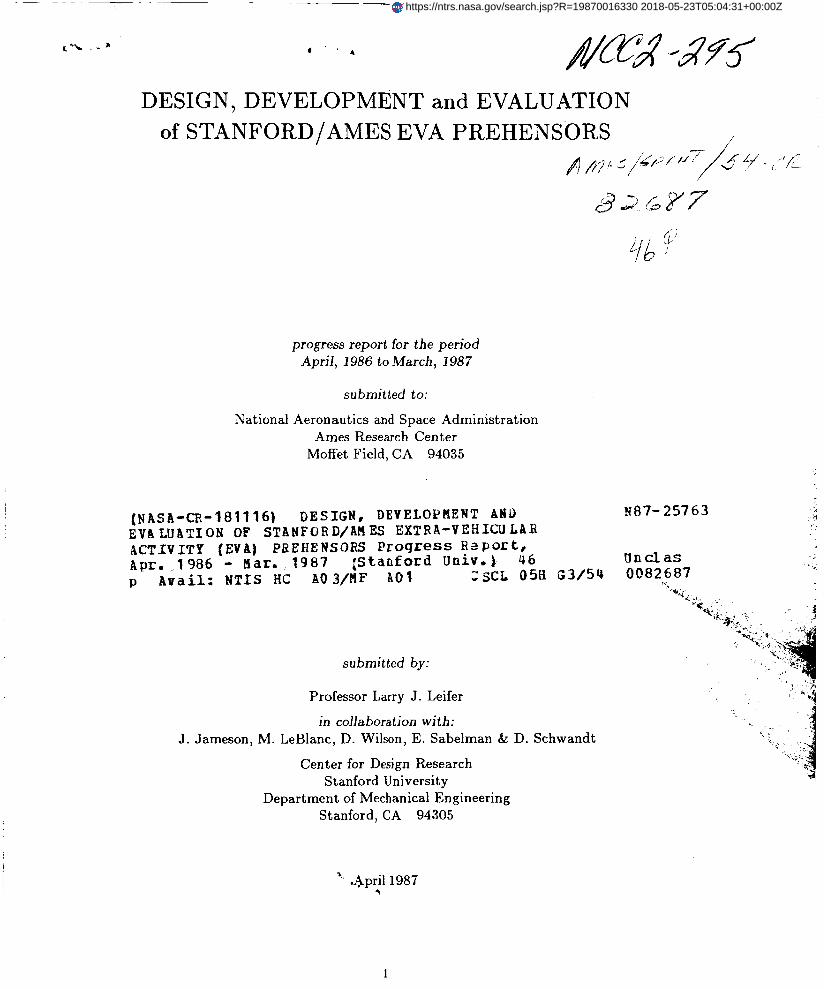
The 6-DOF prehensor has been fabricated in a suit-compatible right-handed version with the exception of the shroud. It was exhibited at the Ames AX-5 Suit Review and subjected to preliminary grasp tests with and without the rotary pressure seals installed. It is presently being fitted with a molded fiberglass shroud [Figure 81 and machined wrist coupling ring.
The 6-DOF prehensor has been demonstrated to be capable of cylindrical, lateral, spherical, three-jaw chuck, tip and hook types of grasp, using a variety of shapes of objects being manipulated [see Appendix C]. It provides superior feedback of grasp force and object shape compared to remotely controlled robotic grippers having greater degrees-of-freedom (e.g. : the Utah/MIT Hand). Initially, the 6-DOF prototype had smooth machine-finish finger tips which limited the ability to grasp articles also having smooth surfaces; later, the distal finger and thumb segments were coated with rubber suspension, which provided increased friction.
4. POWER-AUGMENTED ANTHROMORPHIC PREHENSOR
Design of an externally powered prehensor having more degrees-of-freedom than six has not been attempted, due in part to the greater-than-expected capability of the 6-DOF prehensor compared to published results of devices such as the Utah-MIT hand. Conversion of the 6-DOF prehensor to a totally motor-driven version for use as a robotic or teleoperator end-effector is being pursued under a separate contract.
Preliminary concepts have also been generated for power- or manually-operated prehensors having anthromorphic fingers, but a non-physiologic relationship of finger planes. One concept permits variation of finger motion plane, so that a large variety of thumb-to-finger angles are available.
5. PERFORMANCE ASSESSMENT WORK STATION (PAW)
Originally the plan for evaluation of EVA prehensor prototypes was to construct a “black box” capable of testing all possible grasp and manipulation modalities. Because of the large number of possible t a sks and because of the need t o test prehensor/suit interaction under simulated near-weightless conditions, this all-inclusive approach has been abandoned in favor of a series of activities more closely resembling actual usage in EVA situations. This test series will be combined with precise biomechanical descriptions of the functional requirements, so that prehensors can be compared to gloved and unemcumbered human hand performance, and with standard and specially-devised performance tests such as are used in rehabilitation assessment following injury to the hand [see Appendix D].
In addition to existing standardized human hand assessment tests and NASA in-house and contracted tests that may be used as is or modified for evaluating prehensor vs. gloved and un-encumbered hand performance, the following performance measurement protocols may be applied to prehensor tasks:
1. Stanford Instrumented Grasp Strength Assessment. Grasps are fundamental to human hand interaction with the environment. Not only must tools, parts and equipment be grasped for manipulation to perform useful work, it is particularly important during EVA that astronauts effectively grasp handrails, cables or bars for positioning, reorientation and
6

Design, Development and Evaluation of Stanford/Ames EVA Prehensors
translation in space. A six degree-of-freedom force/moment transducer [Figure 91 may be adapted to measure applied forces and moments in each of the three orthogonal directions (x,y,z), for various types of grasp, including: (1) hook, (2) cyclindrical, (3) spherical, (4) three-jaw chuck, (5) palmar, (6) lateral, (7) finger tip, and (8) hoop grasp.
A variety of functional hand tasks will be identified to represent the broad spectrum of possible hand functions. Included are tasks already envisioned for EVA. In addition, tasks experienced during daily living will be implemented as a means for assessing unexpected capabilities for use in future EVA planning. Assessment will be both qualitative and quantitative, depending upon the specific task. A simple point system may be used with partial credit given for successful completion of portions of a task , as defined for each task.
3. University of Minnesota Tracking System. Developed by James Carey at the University of Minnesota, this state-of-the-art diagnostic tracking system uses a power (cyclindrical) grasp dynamometer to track force, and a finger joint goniometer to track joint angle, as a diagnostic tool and an assessment tool to monitor patient progress in therapy. The subject must try to follow a set waveform pattern on a computer screen. The software captures the trail of joint angle or force superimposed on the target track, and then statistically computes the tracking error. Possible tracking strategies include: (1) joint angle, angular velocity and acceleration; and (2) individual joint or grasp force/moment generation. It is possible that an important motion with specifc velocity profile may be unattainable with a gloved hand or one of the prehensors, and this will objectively demonstrate any limitations. The University of Minnesota has provided us with a copy of their software and a list of computer hardware needed for implementation.
2. Stanford Functional Hand Task Assessment.
Since the decision was made to concentrate on off-the-shelf performance assessment protocols, equipment fabrication related to the PAW has been minimal. A JR3 °ree-of-freedom force- moment sensor was obtained for a temporary trial, and was found to be suitable for purposes of the PAW either as a stand-alone device [Figure 91 or attached to another structure such as a rotary crank.
PLANS FOR FUTURE WORK
In September, 1986, a draft supplementary proposal was prepared for submission to NASA- ARC in May, 1987 to add development of graphic simulation software for real-time dynamic analysis of prehensor design and control to the project. This phase would complement development of the PAW by generating a computer model of each prehensor and its properties, with the potential for predicting performance rather than relying on post facto testing to refine a design. To the extent that objects in the user’s environment are included in the model, it could also be valuable as a training tool for reducing the learning period necessary for the user community to switch from glove to prehensor.
Inasmuch as several of the investigators are involved in projects of the Rehabilitation R&D Center of Palo Alto Veterans Administration Hospital, it would be beneficial t o integrate studies of prehensor performance with similar investigations of hand biomechanical anatomy and function. For example , a proposal h a s been submitted for VA review (authors: Sabelman, Schwandt, et al) to develop a high-resolution computer model of human hand anatomy and biomechanics, with the capability of illustrating response of soft tissues ot objects in the environment. I t would require little modificaiton to model the prehensor/hand interface, and possibly predict sites of excess pressure on the skin and abnormal muscle or tendon angle. A second proposal is in preparation (authors: Hentz, Schwandt, Sabelman) to implement
7

/
Design, Development and Evaluation of Stanford/Ames EVA Prehensors
performance assessment for rehabilitation purposes using the same parameters adn task reconstruction as proposed above for EVA prehensors. All integrated studies would contribute to and be subject to the conditions of existing NASA-VA Technology Transfer Agreements.
8

Design. Development and Evaluation of Stanford/Ames EVA Prehensors
PUBLICATION AND PRESENTATIONS
1. JPL Telerobotics Conference (two papers) 2. Ames AX-5 suit review
BIBLIOGRAPHY
Bender, L.F. Prostheses and Rehabilitation After A r m A mputation, (Springfield, IL: C.H. Thomas), ch. 9, pp. 122-137, 1974.
Blaschke, A.C., Santschi, W.R. “Studies t o determine functional requirements affecting hook fingers design”, Univ. of Calif. Dept. of Engineering Special Technical Report No. 12, pp. 1-21, May, 1949.
Brooks, T.L., Bejczy, A.K. “Survey of hand controllers for teleoperation” , J P L Invention Report NPO-16610/6105, R.S. Jamieson, ed., pp. 1-72, Jan., 1986.
Gilad, 1. “Motion pattern analysis for evaluation and deisgn of a prosthetic hook”, Arch Phys Med Rehabil, v. 66, pp. 399-402, 1985.
Jacobsen, S.C., Wood, J.E., Knutti, D.F., Biggers, K.B. “The Utah/MIT dextrous hand: Work in progress”, Robotics Research, (Cambridge, MA: MIT Press), pp. 601-653, 1984.
Klopsted, P., Wilson, P. et al, Human Limbs and Their Substitutes, (McGraw-Hill), 1954.
Radocy, R. “Voluntary closing control: A successful new design approach to an old concept”, Clin Prosth t3 Orthotics, v. 10, pp. 82-86, 1986. Santschi, W.R., ed. Manual of Upper Eztrernity Prosthetics, 2nd. ed. (UCLA Dept. of
Taylor, C. & Schwarz, R., “The anatomy and mechanics of the human hand”, ArtificiaE Limbs, v.2, no. 2, May 1955.
Engineering), ch. 4, pp. 39ff, 1958.
ILLUSTRATIONS
Fig 1. Spectrum of dexterity Fig 2. Basic forms of grasp Fig 3. I-DOF overview: (A.) plan view, (B.) lateral view Fig 4. 1-DOF two-finger Roberts linkage end effector Fig 5. I-DOF three-finger end effector Fig 6. 2-DOF overview: (A.) plan view, (B.) lateral view Fig 7. 6-DOF finger control mechanism: (A.) plan, (B.) side view Fig 8. 6-DOF shroud configuration Fig 9. PAW force & moment transducer
APPEND1 CES
A. Original proposal B. Continuing agreement proposal of March, 1986 C. Jameson paper from JPL Telerobotics conference D. PAW test options
9

c 0 ca 0 L.
r I- E L. a> Q X w
- 8
E 0
R c,
a R

n a z v)
0
Y 0 0 I
L
n F
A
U W
J
a
G
a v)
J
U W I v)
Qu -
a
U a 3 2

I
3 Q) .& > d cd +
pc
a
z .. 3 Q) .& Q) > 0
b4 0 f2 +
I
s Q)
> .r(
m


3 .d >
cd W L


B
c Q) L 3 bo L .-
I
U u1 I

Figure 8. 6-DOF shroud configuration
. .-

0 ccr

Cooperat ive Agreement Proposal
for
D e s i g n and Development of an
FXA Prehensor
Submitted t o
NASA-Ames Research Center Mountain View, Cal i fornia
For Work by Stanford University
. Stanford, California
October 1983

-1-
. In t roduc t ion
This proposal has generated from discussion by t h e s t a f f of NASA-Ames L i f e Sc iences /Man-Machine Sys tems and t h e f a c u l t y of S t a n f o r d U n i v e r s i t y ' s Mechanical Engineering Department/Design Div i s ion .
Problem Statement
I n present manned space exploration, a s t ronau t s wear p ro tec t ive s u i t s w i t h g l o v e s for manual f u n c t i o n s . I n f u t u r e e x t r a - v e h i c u l a r a c t i v i t y (EVA) manned space explorat ion, t h e present gloves w i l l comprise d e x t e r i t y due t o t h e fo l lowing f ac to r s :
0 Increased space s u i t p re s su r i za t ion 0 Increased thermal hazard 0 Increased r ad ia t ion hazard 0 Increased r i s k of accident
P r o j e c t Object ive
The g o a l of t h e p r o j e c t I s to produce a work ing p r o t o t y p e of a hand prehensor which w i l l funct ion s a t i s f a c t o r i l y i n the hazardous EVA manned space environment.
The ob jec t ive t h e prehensor
0
0
of the design prototype i s t o a l low an a s t ronau t t o opera te i n such a manner that:
t h e hand is i n a safe environment and only the prehensor i s i n t h e hazardous environment the prehensor can perform requi red func t iona l t a s k s t h e system is acceptable t o t h e a s t ronau t s f o r wear and use
Approach
The g e n e r a l p l a n i s t o b r i n g knowledge f r o m t h e f i e l d s of r o b o t i c s and p r o s t h e t i c s t o bear on t h i s man-machine problem. Experience and technology from these two f i e l d s i s not of ten shared but is re levant t o t h e problem at hand and i s access ib l e through the i n v e s t i g a t o r s involved.
I t i s g i v e n t h a t a r m m o t i o n s o t h e r t h a n t h e hand can be ach ieved s a t i s f a c t o r i l y I n EVA m i s s i o n s by p r e s e n t l y known t e c h n o l o g y and, t h e r e f o r e , w i l l n o t be cons idered in t h i s p r o j e c t . Tha t i s , s h o u l d e r , elbow, forearm and w r i s t functions w i l l be excluded. Only t h e prehens i le func t ions of the hand a r e included i n t h e o b j e c t i v e .

The s p e c i f i c s t e p s for conducting the goal of t h e p r o j e c t a r e a s fo l lows:
1) Review t h e l i t e r a t u r e of t echno logy i n r o b o t i c s , p r o s t h e t i c s , c o n t r o l and machine in te l l igence .
2) V i s i t key f a c i l i t i e s t o assess cu r ren t work I n p r o s t h e t i c t e r m i n a l d e v i c e s and m a n i p u l a t o r s f o r n u c l e a r , u n d e r w a t e r and o t h e r a p p l i c a t i o n s -
3) Document t h e f a c t o r s c r i t i c a l i n EVA m a n i p u l a t i o n s , e.g. g r a s p , s ensa t ion , c o n t r o l , dex te r i ty , too l ing , s a f e t y , and f a t igue .
4) Specify performance requirements f o r t he man-machine prehensor i n t h e form of a dec is ion matr ix by which t o eva lua te designs.
5 ) Val ida te performance requirements w i t h NASA-Ames s t a f f .
6 ) Generate ideas f o r s o l u t i o n of problem, s e l e c t t h e most promising ideas , and bu i ld four concept models.
7 ) Together w i t h NASA-Ames s t a f f , select one p re fe r r ed des ign using the dec is ion mat r ix as a guide.
8) Build a f u n c t i o n a l prototype of t h e p re fe r r ed design.
9 ) T e s t t h e p r o t o t y p e i n t h e S t a n f o r d U n i v e r s i t y l a b o r a t o r y t o t r o u b l e shoot any obvious flaws- Modify prototype i f necessary.
10) T e s t t h e p r o t o t y p e a t NASA-Ames i n h a z a r d o u s e n v i r o n m e n t cond i t ions to assess performance a g a i n s t requirements.
Document t h e p r o j e c t and i t s r e s u l t s by means of w r i t t e n r e p o r t and v ideo tape.
11) .I
12) Pursue f u r t h e r development as i nd ica t ed in t h e second year.
Time Schedule 1 I
yea r 3 6 9 mos. mos .
I I I I
\ \ c / / /
review l i t e r a t u r e genera te designs select 1 design test pro to type Phase v i s i t f a c i l i t i e s bu i ld 4 models bu i ld pro to type document resultp Two spec. pe r f . req'mts.
Rbsources
The Mechan ica l E n g i n e e r i n g Department a t S t a n f o r d i s w e l l q u a l i f i e d and equipped t o conduct t h e proposed work. It has over 20 yea r s of a n a l y t i c a l and p r a c t i c a l experience i n t h e design of robots and man-machine systems. A major p r o j e c t dea l ing wi th i n t e r a c t i v e robots f o r quadr ip l eg ic s has been underway for , f i v e years a t the VA Medical Center i n Pa lo Alto.
The P r o s t h e t i c S e r v i c e a t Ch i ld ren ' s H o s p i t a l a t S t a n f o r d h a s been provid ing a r t i f i c i a l arms t o amputees s i n c e i t opened n ine yea r s ago. This t e c h n o l o g y has I n c l u d e d b o t h b o d i l y powered and e x t e r n a l l y powered v a r i e t i e s of hook and hand te rmina l devices. Important i n t h i s work w i t h amputees, as i t i s w i t h quadriplegics, is t h e psychosocial acceptance of t h e devices.
I n v e s t i g a t o r s L e i f e r and LeBlanc h a v e s o l i d f o u n d a t i o n s i n t h e neuromuscular biomechanics, k i n e s i o l o g y , and motor c o n t r o l n e c e s s a r y t o u n d e r t a k e t h i s work and c o n t r i b u t e t o t h e s t a t e of t h e a r t . C u r r i c u l a v i tae a r e a t tached.
I n c o m b i n a t i o n w i t h o t h e r r e s o u r c e s and p e o p l e a v a i l a b l e a t S t a n f o r d Un ive r s i ty , t h e VA Medical Center i n P a l o Alto, and Children's Hosp i t a l a t S tanford , a unique opportunity ex i s t s f o r i n f u s i o n and innovation.
Staff
L. L e i f e r w i l l d i r e c t t h e p r o j e c t , e v a l u a t e d e s i g n i d e a s , and p r o v i d e l i a i s o n w i t h NASA-Ames s t a f f , M. LeBlanc v i11 c o n t r i b u t e p r o s t h e t i c e x p e r i e n c e and t e c h n o l o g y t o t h e p r o j e c t by v a y of prob lem a n a l y s i s , performance s p e c i f i c a t i o n s , design ideas, eva lua t ing models, and preparing t h e w r i t t e n r e p o r t . J, Jameson, a long w i t h L, L e i f e r , v i11 c o n t r i b u t e r o b o t i c s e x p e r i e n c e and technology to t h e p r o j e c t by way of problem a n a l y s i s , performance spec i f i ca t ions , des ign ideas , eva lua t ing models, and p r e p a r a t i o n v i d e o documenta t ion . G. Toye and J- L a n g s t o n w i l l conduct l i t e r a t u r e searches, con t r ibu te design ideas , bu i ld t h e f o u r models, assist i n eva lua t ion of models, cons t ruc t the working prototype, snd l a b test t h e p ro to type a t Stanford.
)
MED 4-84-N
Estimated budget f o r a per iod of one year beginning December 1, 1983
1. S a l a r i e s
Prof . L. l e i f e r , P r inc ipa l Inves t iga tor 5% time academic year 5% t i m e summer
J. Jamenson - 20% time G. Toye-Student Research Assistant-50% t i m e J. Langston-Student Research Assistant-50% time
S e c r e t a r i a l Services-30% t i m e Total Direct S a l a r i e s
11. Univers i ty Staff Benefi ts - 23.5% of salaries through 8/31/84, 23.9% t h e r e a f t e r
111. M. Ie Blanc, Collaborating Inves t iga tor a t Chi ldren ' s & s p i t a l Rehabi l i ta t ion Engineering Center (see a t t ached)
$2,390 783
6,450 9,110 9,110
6,000 3-333-3
7,987
_- --\--. I r r
/:- * $24,695
I V . Miscellaneous suppl ies , computer supp l i e s , L-- . photocopy cos t s , communication 1,300
Graphic Services 1,800 )
Travel-Langston, Toye, Perceptronics (LA) Leifer, LeBlanc, Boeing Corp. ( S e a t t l e ) , Jamenson, Iangston, NOSC (San Mego) 3,750
Report preparat ion and reproduction 1,200
Engineering Support Services - 1.53% of gross p r o j e c t cos t s 2,295
Modified t o t a l d i r e c t cost6 76,870
Univers i ty Overhead-69% of Modified t o t a l d i r e c t cos t s
Equipment
Force Instrumentation-to be fabr ica ted Kinematic instrumentation-to be f a b r i c a t e d Concept-model hand ampl i f ie rs (4) t o be
Funct iona l prototype hand amplif ier- to f ab r i ca t ed
be fabr ica ted
53,040
20.090
Tota l amount requested $150,000

.0 -5- * CHILDRENS HOSPITAL at Stanford
520 Willow Road, Polo Alto, California 94304 / (415) 3274UXI
November 1 4 , 1983
Mr. Robert Burtman Research Coordination Off ice S tanford Univers i ty School of Engineering Building 530 Stanford , CA 94305
Dear M r . Burtman:
Conf l r m i n g your t e l ephone conve r sa t ion las t week wi th Ken J e n s e n , D i r e c t o r of Finance a t C h i l d r e n ' s H o s p i t a l , below i s conf i rmat ion of Maurice LeBlanc's s a l a r y and bene f i t s f o r him t o s e r v e as a consul tant on the NASA propoal which Professor Le i f e r is preparing:
Sa la ry $51,00O/year @ 40% $ 20,400 CH@S Fringe Benef i t s @ 21.05% 4,295
Total: $ 24,695
Sincerely,
Colet te Duncan Financial Analyst

. ..
DESIGN, DEVELOPHENT, and ASSESSPLENT of an
EVA PREBENSOR
a c o n t i n u i n g c o o p e r a t i v e agreement p r o j e c t p r o p o s a l
s u b m i t t e d t o t h e
NATIONAL AERONAUTICS and SPACE ADMINISTTRATION Ames Research C e n t e r
Moffe t F i e l d , CA 94035
s u b m i t t e d by :
P r o f e s s o r L a r r y J. L e i f e r Cen te r f o r Des ign R e s e a r c h
S t a n f o r d U n i v e r s i t y .
Department of Mechanica l E n g i n e e r i n g S t a n f o r d , C a l i f o r n i a 94305
firth 1986

INTRODUCTlON TO TEE PROBLEM
The development of a new c l a s s of human-powered s p a c e s u i t "end e f fec tors" , or " p r e h e n s o r s " h o l d s p romise t o e x t e n d t h e d e x t e r i t y , m i s s i o n d u r a t i o n , and s a f e t y of EVA a s t r o n a u t s . The major t h r u s t s of t h e p r o j e c t are p r e s e n t e d as f o l l o w s :
1. p r e h e n s o r s d e r i v e d f rom p r o s t h e t i c s r e s e a r c h ( t h e s e p r e h e n s o r s are p r e s e n t l y i d e n t i f i e d as "PP-1 and PP-2");
2. t h e "Direct L ink P r e h e n s o r " (DLP) , a t h r e e - f i n g e r e d , s emi -an th ropomorph ic , s i x degree-of -f reedom p r e h e n s o r ;
3. t h e "Hi-Fi hand" (HF), a n an th ropomorph ic , power-augmented p r e h e n s o r ;
4 . t h e "Pe r fo rmance Assessment W o r k s t a t i o n " (PAW), c o m p r i s i n g a n i n t e g r a t e d set of manual d e x t e r i t y t a s k s , and p o s s i b l y a c o m p u t e r i z e d m o n i t o r i n g s y s t e m ,
The above items are d i s c u s s e d i n more d e t a i l i n t h e o r i g i n a l p r o p o s a l , which is i n c l u d e d i n t h e a p p e n d i x (under t h e s e c t i o n e n t i t l e d "Approach") .
TASK SPEC IF ICATION
The c u r r e n t s t a t u s of e a c h of t h e items above a l o n g w i t h p r o g r e s s s c h e d u l e s for t h e p roposed g r a n t year are p r e s e n t e d i n t h e f o l l o w i n g . Note t h a t t h e e rgonomic a n a l y s i s ment ioned i n t h e o r i g i n a l p r o p o s a l h a s been d ropped f rom t h e p r o j e c t due t o s h i f t s i n p r i o r i t i e s .
1. P r o s t h e t i c P r e h e n s o r s - The f i r s t " s p a c e s u i t r eady" v e r s i o n , PP-1, i s e x p e c t e d t o be comple t ed b y the b e g i n n i n g of t h i s g r a n t y e a r . A c o n c e p t u a l model of a n enhanced v e r s i o n h a s been c o n s t r u c t e d and w i l l serve as a bas i s fo r PP-2, which is t o be comple t ed ( s p a c e s u i t r e a d y ) by O c t . 1, 1986. T e s t i n g of PP-1 and PP-2 w i l l be t h e n be per formed u s i n g t h e PAW (see below), The remainder of t h e g r a n t y e a r w i l l t h e n be d e v o t e d t o t h e c o n s t r u c t i o n of a c o n c e p t u a l p r o t o t y p e of a t h i r d v e r s i o n (PP-3).
2. Direct Link P r e h e n s o r - The f i r s t v e r s i o n of t h i s p r e h e n s o r (DLP-1) i s c u r r e n t l y b e i n g f a b r i c a t e d . It i s e x p e c t e d t o be as sembled by A p r i l 1, 1986. Dur ing t h e proposed g ran t y e a r t h i s p r e h e n s o r s h a l l be mounted o n t h e NASA Ames AX-5 s p a c e s u i t and t e s t e d w i t h t h e PAW. R e s u l t s from t h e s e t e s t s w i l l h e l p p o i n t t h e way t o a more r e f i n e d v e r s i o n (DLP-2). T h i s new v e r s i o n i s e x p e c t e d t o be q u i t e s imi la r to t h e o r i g i n a l v e r s i o n , e x c e p t f o r small r e f i n e m e n t s i n d e s i g n , s u c h a s c o n t r o l s which a r e more compa tab le and are a d j u s t a b l e t o f i t v a r i o u s hand s i z e s , o r a l t e r a t i o n of t h e a n g l e of t h e "working plane" of t h e thumb w i t h r e s p e c t t o t h e f i n g e r s . DLP-2 i s t o be completed and t e s t e d t h e end of t h e proposed ):rant y e a r .
3. HI-FI Hand - Work on t h i s p r e h e n s o r is s c h e d u l e d t o b e g i n a t t h e o u t s e t of t h e p roposed g r a n t y e a r . Exper ience g a i n e d f rom t h e t h e d e s i g n of t h e Direct Link P r e h e n s o r has lowered our e x p e c t a t i o n s f o r a a c h i e v i n g a

r e a l i s t i c design of a highly anthromorphic prehensor, p a r t i c u l a r l y because of t h e assoc ia ted l a rge number of degrees-of-freedom. Hence, a more modest concept i s evolving which i s s i m i l a r t o the DLP, but with add i t iona l f e a t u r e s such as:
a. one t o t h r e e add i t iona l degrees-of-freedom, such as thumb f l ex ion and extension i n two d i rec t ions in s t ead of one f o r t he DLP, o r allowing the two f i n g e r s opposing the thumb t o spread a p a r t ;
b. power augmentation - re ta in ing a d i r e c t l inkage s y s t e m but adding power augmentation (s imilar t o power s t ee r ing ) has the p o t e n t i a l of (1) reducing the range of motion of the human hand required t o opera te the prehensor, r e su l t i ng I n a smal le r , l e s s cumbersome pressure enclosure, ( 2 ) reducing astronaut f a t i g u e , and (3) enhancing f o r c e feedback.
Note t h a t t he s implest form of power augentat ion would be t o use a s i n g l e ex te rna l ly powered ac tua to r such t h a t i t operated the j o i n t s of t h e prehensor i n unison t o achieve a "power grasp", leaving the human power for small, manipulative t a s k s . A working concept model of t h e HI-FI hand, s u f f i c i e n t l y robust t o allow f o r d e x t e r i t y t e s t i n g , is t o be completed by the end of t he proposed grant year.
4. Perfonnance Work S ta t ion - Work on t h i s system has been delayed due t o a g rea t e r emphasis placed on PP-2, but completed drawings of PAW-1 w i l l be ready a t t h e beginning of the proposed grant year. Fabr ica t ion and assembly are scheduled t o be completed by June 1, 1986. In tegra t ion of t h e hardware with a computerized monitoring s y s t e m is t o be completed by August 1 , 1986. Tests with PAW-1 w i l l be performed before and a f t e r t h e computer i s added.

, . PROPOSAL: ME 25-85 RENEWAL
NASA NCC 2-295
Estimated Budget f o r a Period of One Year Beginning Apr i l 1, 1986
I. Direct Sa la r i e s
A. Professor L.J. Le i fe r , Pr incipal Inves t iga tor 1 . 5% t i m e academic year 2. 5% t i m e summer
B . One (1) Research Assoicate, 50% t i m e
C. One ( 1 ) Graduate Student Research Ass i s t an t , 50% time
D. One (1) Graduate Student Research Ass i s t an t , 50% t i m e
E. Sec re t a r i a l Services - 11% t i m e
TOTAL DIRECT SALARIES :
11. University Staff Benefi ts
$ 3,026 967
18,020
10,222
9,602
2,556
$44,393
$11,327
A . 25.4% of s a l a r i e s thru 08-31-86 B. 25.6% of s a l a r i e s t he rea f t e r
111. Consultant Fees 12,047
I V . Miscellaneous: supp l i e s , communications photocopy c o s t s , e tc . 300
V. Report preparat ion and reproduction 300
V I . Travel to Johnson Space Center 740
V I I . Computer Maintenance and Supplies 6,293
V I I I . Engineering suppport services - 1.72% of Gross project cos t s 2,580
MODIPlED TOTAL DIRECT COSTS: $77,980

I X . University overhead
A. 69% of modified t o t a l d irect cost thhl 08-31-86 B . 73% of modified t o t a l d irect cost thereafter
X. Equipment (to be fabricated)
A. Prehensor Evaluation Lab B. Prosthet ic Prehensor C. Dexterous Passive Prehensor D. Power Prehensor
X I . Subcontract - Childrens Hospital ( s e e IV above portion not subject t o University Overhead.
ToTIIl. ANNUAL AMOUNT BEQUESTED
$ 2 2 . 4 19 3 3 , 2 0 6
2 0 0 1,000
500 2,000
12,695
$150,000

REPORT ON T H E STANFOKWAMES DIRECT-LINK SPACE SUIT PREHENSOR
John W. Jameson
Mechanical Engineering Dept., Design Division, 5th Floor Terman Engineering Center, Stanford, CA 94305
Abstract
Researchers at the Center for Design Research at Stanford University, in collaboration with NASA Ames at Moffet Field, California, are developing hand-powered mechanical prehensors to replace gloves for EVA spacesuits. This paper covers the design and functional properties of the fust version "Direct Link Prehensor" (DLP). It has a total of six degrees-of-freedom and is the most elaborate of three prehensors being developed for the project. The DLP has a robust design and utilizes only linkages and revolute joints for the drive system. With its anthropomorphic configuration of two fingers and a thumb it is easy to control and is capable of all of the basic prehension patterns such as cylindrical or lateral pinch grasps. Kinematic analysis reveals that, assuming point contacts, a grasped object can be manipulated with three degrees-of-freedom---yet in practice more degrees-of-freedom are possible.
1.0 Introduction
One of the greatest difficulties astronauts encounter during EVA is simply the use of their hands, resulting primarily from the high stiffness of the gloves due to the suit's pressurization. Although space suit glove technology has improved markedly in - !he past several years, the hisher suit pressures expected for future EVA'S will s igacant ly offset these improvements. This and other considerations provide the motivation for the development of hand-powered space suit prehensors (see the reference article [3] for more general background on the prehensor project).
The primary goal for the design of the DLP was to incorporate as many degrees-of-freedom as possible while maintaining ruggedness and reliability. An anthropomorphic configuration was selected partly because of its proven effectiveness and partly because of the difficulty humans have with simultaneously controlling more than two or three degrees-of-freedom unless the corresponding motions are "natural".
The motion of the operator's hand is conveyed to the mechanical fingers by a system comprised purely of linkages connected by revolute joints. The minimization of moving parts, along with the absence of cables or gears, results in the DLP possessing smooth, accurate, and sensitive finger conwl with good force/position reflection.
2.0 Finger Geometry and Control
Figure 1 shows two photos of the DLP (version I) and indicates the basic components of the device, namely, the mechanical fingers, the "shroud ears", and the control mechanisms. Note that the entire shroud has not been completed yet. It shall be molded of fiberglass around the shroud ears and provide a pressurized environment around the astronaut's hand. The whole assembly -will then be attached to the space suit in the same manner as a glove. The first version DLP shown in the photographs can fit approximately 95% of the U.S. male population and withstand large grip forces (roughly 150 pounds). Note that most of the DLP is fabricated from aluminum.
The motion of each mechanical fmgerlthumb of the DLP is restricted to a corresponding plane, as best observed in Figure 2, and the planes of motion are all perpendicular to a common plane called the "palm plane" (this phrase is used in the following only to connote orientation, i.e., the

position of the palm plane is not important). The angle between the planes of motion of the mechanical "index" and "ring" fingers is fifteen degrees. In the following, it is convenient to define the "average finger plane of motion" (AFPM) as that plane which is also perpendicular to the palm plane and which bisects the angle between the index and ring mechanical finger planes of motion. The angle between the plane of motion of the mechanical "thumb" and the AFPM is fifty-five degrees. The index and ring fingers are separated oriented such that their tips almost touch when the fingers are substantially curled, hence providing tip prehension for small objects.
Figure 3 shows plan and side views of the index and ring finger control assemblies, without the shroud ears. The index and ring fingers are identical in construction and each have three links, referred to as the proximal, medial, and distal links, and three corresponding revolute joints. Each finger, however, has only two degrees-of-freedom since the motions of the medial and distal links are coupled by a coupler linkage. This coupling results in a curling motion of the fingers similar to that exhibited by human hands, and is particularly useful for "power grasps" such as cylindrical or spherical grasps (see Sec. 4.0). Note that a "palm" is attached to the shroud ears (see Figure 1 a) to assist in these types of grasps.
The motion of the operator's hand is transmitted through a system of control linkages (see Figure 3). These linkages, along with the pushrods, form a set of (approximate) parallelograms which keep the mechanical fingers in the same orientation as the control linkages. In order to provide controls which operate most comfortably, the joints of the control linkages should pass through the corresponding joints of the hand. However, the planes of motion for the control linkages for the (mechanical) index and ring fingers are parallel---which is not the case for a human hand since the proximal (or metacarpophalangeal) joints for the latter form an arch. This fact is manifested as a slight discomfort when the hand of the operator is closed (in a fist). The DLP could be constructed such that the said planes correspond more closely to a human hand, but the shroud was found by the author to be impractically large due to the resulting mechanism.
1
(4 Figure I Photos of thefirst version DLP

(-
Motion is imparted to t h e n t r o l 11- t h r G t h e medial and distal links (or second and third phalanges) of the operator's hand, and each phalange tailor-fitted to a nng attached to a corresponding control linkage. For the thumb, both the proximal and distal links (or f i i t and third phalanges) have ring attachments to the control linkages.
Control of the DLP is natural since the configuration of the mechanical fingers parallels that of the operator's hand; in a sense, the mechanical fingers appear as a "projection" of the human fingers which control them. The thumb and index fingers of the operator control the similarly juxtaposed mechanical thumb and index finger; the mechanical ring finger is controlled by moving the operator's middle, ring, and little fingers in unison. The only possible alternative for control allocation would be to let the operator's little finger alone control the mechanical ring finger since it is virtually impossible for one to move his or her index and middle fingers (in unison) independently of the ring and little fingers (in unison).
As with the mechanical fingers, the motions of the medial and distal control linkages are coupled by a coupler linkage (see Figure 3). Although the distal control linkages are not absolutely necessary to control the motion of the mechanical fingers, they are included to facilitate the fine control needed for manipulation of objects. In order to minimize the weight (and inertia) of the controls, the distal control linkages have low mass and strength properties. However, when the operator imparts a grip force on the distal linkages over a prescribed amount, damage is avoided by mechanical ovemde mechanisms which allow the distal linkages to rotate beyond the positions determined by the coupler linkage.
The ratio of motion of the control linkages to the mechanical fingers is approximately 1.00 to 1.07. This essentially allows the mechanical fingers to reach useful positions which would otherwise result in collisions between parts of the control linkages.
The f i t version DLP incorporates ball bearings for the control linkages and bushings for the remaining joints. With this arrangement, most of the friction in the drive system arises from the teflon rotary seals located around the concentric shafts (two shafts for each fingedthumb), the axes of which pass through the corresponding proximal joints of the mechanical fingers/thumb. These seals allow transmission of finger motion via rotary motion across the pressure differential of the shroud wall.
.
.- .~
3.0 Other Geometric Characteristics
An important factor affecting prehensor (and glove) performance is the location of the "neutral position" of the suit's flexible wrist joint compared with that for the operator's hand. The neutral position of the operator's wrist corresponds to the long axis of his forearm when the latter, along with the palm of the hand, is laid flat on a supporting surface. From this position the wrist can be flexed and extended approximately q u a l angles. Ideally, this position also corresponds to the neutral position of the wrist joint for the suit, a circumstance detennined by the prehensor (or glove) design. As shown in Figure 4, for the first version DLP the operator's hand is extended approximately twenty degrees beyond its neutral position for the corresponding neutral position of the wrist assembly, which unfortunately results in twenty degrees less ex5nsion capability than the ideal case (note that z,,, is the neutral axis for the wrist joint, and zoh is the neutral a x i s for the operator's wrist). This disadvantage stems from the presence of the thumb control mechanism---a problem which shall be addressed for future designs to a degree proportional to how badly the overall performance of the DLP is affected. Note that the diminishment of wrist mobility is not a problem for gloves.
Another factor affecting prehensor performance is the geometrical relation between the mechanical finger ensemble and the operator's hand. Denoting a reference frame fixed with respect to the mechanical finger ensemble as MH (for "mechanical hand"), and denoting a similar frame fixed with respect to the hand as OH, then for a hypothetical prehensor design six parameters are needed to specify the position and orientation of OH with respect to MH. How these parameters affect overall EVA performance depends partly on ergonomic considerations, such as having the task space comfortably located in front of the operator's face, and partly on manipulation issues,

f
ORIGIWAL' PAGE IS OF POOR QUALITY
"index"
Figure 2 Planes of motion for the mechanical fingers
I
I 4 Mechanical
Fingers I
Ffflger Controls
!
i
Pressure seals located 011 concentric shafts
Plan View d Finger Control Mechanism (fingers extended) (finger curled)
Side View of Finger Control Mechanism
Figure 3 Plan and side views of the index and ring finger control assemblies (shroud omitted)

s u c h a e a b w o f the operator to rn-e mechanical finger%i&ons/forces to his o w 5 motions/forces. The configuration for the DLP, described in the next paragraph, resulted to a large extent from the desire to implement the uncomplicated linkage system.
Figure 4 shows the relationships between the MH and OH Cartesian frames for the first version DLP when the wrist joint is at its neutral position, where the x-axes of both frames are perpendicular to the page. The orientations of OH and MH are identical and the xz-plane of each corresponds to the plane of the fingers when they are fully extended. Each respective x-axes lies along a l&e-(approxima&ly) connecting the corresponding fmt (or metacarpophalangeal) joints. Note that p is the position vector of the origin of MHk-ith respct to OH---it lies in the yz-planes of MH and OH and is 6.25 inches long.
4.0 Prehension Patterns
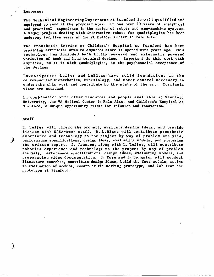
In spite of the limitation of planar motion of the mechanical fingers, the DLP is capable of all the basic prehension patterns and, when in the' hands of a moderately experienced operator, can manipulate objects with a surprising degree of dexterity. Figure 5 shows three forms of tip prehension which are commonly used for manipulative tasks. Figure 6 shows (a) cylindrical, (b) spherical, and (c) lateral pinch grasps. The former is especially important for astronaut mobility because of the use of hand rails for EVA locomotion. Figure 7a shows a useful grasp for turning a screw driver (by rotating the forearm), and Figure 7b shows how a powered rotary tool can be operated.
.- - __
Figure 4 The neutral axes and the relatiomhip between MH and OH
_. - _- 5.0 Manipulative Capability
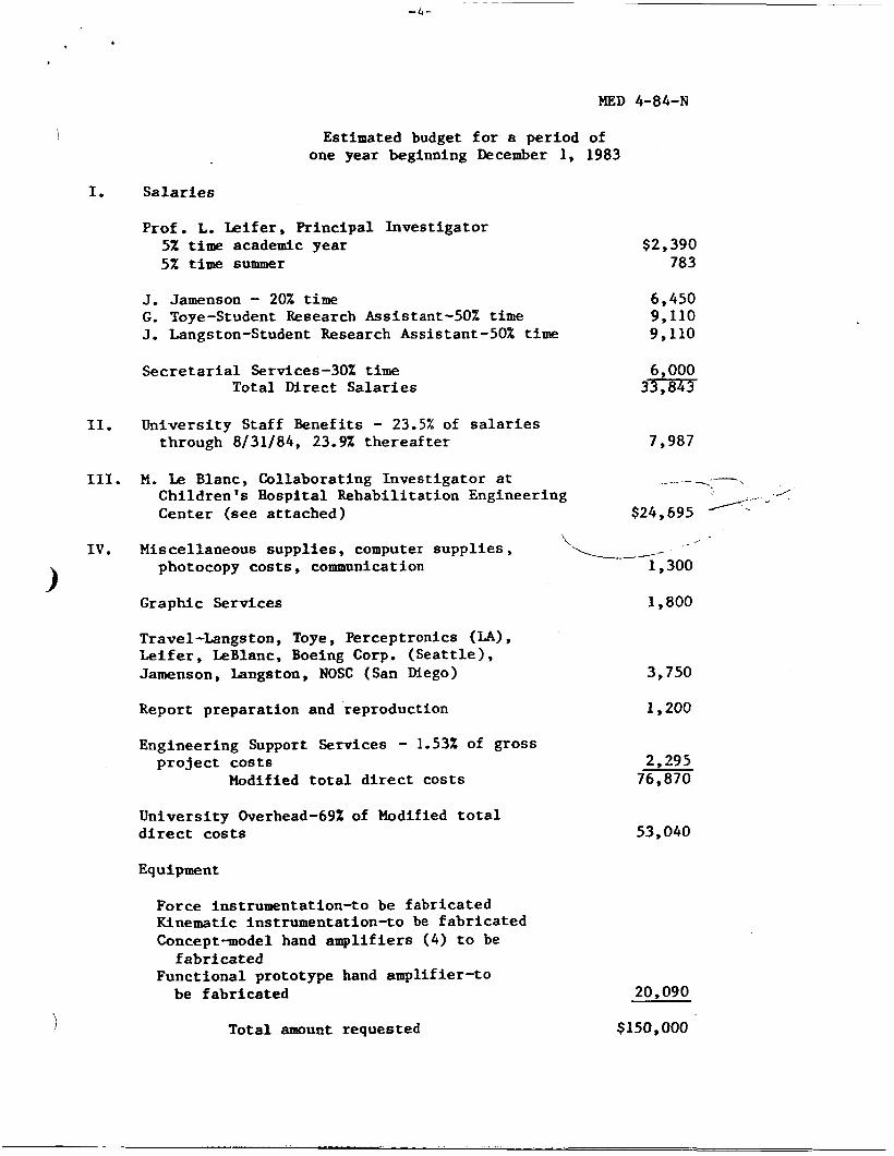
Tip prehension is the most common pattern used for manipulation, and for the DLP this may be with either two or three finger tips. For the latter case, assuming point contacts between the finger tips and the object, kinematic considerations reveal that the object can be manipulated with three degrees-of-freedom with respect to the hand. However, since sliding can occur at some contacts without seriously disrupting the stability of the grasp, manipulations which do not quite conformi& above ideal case armmihk , Considering the idealized case presently, the velocity of a contact point on the object can be written as
vi= q, + w+, X xi, for i=1,2,3
where y is the velocity vector of the ith contact, q, and w+, are the velocity vector and angular

f
Figure 5 Three forms of tip prehension
(a) fb)
Figure 6 Cylindrical, spherical, and lateral pinch grasps
ORIGINAI; FKGE Is OF POOR QUALITY
Figure 7 Two other usefizl grasps for the DLP
velocity vector, respectively, of the object with respect to the hand, and gi is the position of the ith contact in the object reference frame. Each contact must move in a corresponding (mechanical finger motion) plane, and, defining these planes by their normal unit vectors e, i=1,2,3, this requirement can be written as
Ei-v i=Q, for i=1,2,3. (2)
Combining eqs. (1) and (2) and expressing the result in matrix form gives:
where Px,i, Py,i, and Pz,i are the components of t i , and rx,i, ry,i, and rGi are the components of q (for i=1,2,3). The homogeneous solutions to eq. 3 represent the possible motions of the object with respect to the hand. For the DLP the matrix in eq. (3) has a rank of three and hence there are (6-3=3) three homogeneous solutions. Figure 8 shows an object grasped at three points (cl, c2, and c3) on the xy-plane of the object frame, and this plane is defined to be parallel to the palm plane. The columns of the matrix corresponding to wx, wy, and vz (the x and y-components of

f
ORIGINAE PlKGll OF POOR QU-
Figure 8 Manipulative components forthe DLP grasping an object with all contacts on a plane parallel to the palm plane
and the z-component of a, respectively) for this case are all completely filled with zeroes, indicating that the object can be manipulated with arbitrary magnitudes of w,, wy, and vz (these components are indicated on Figure 8). Note that this is only the case when all contacts are in a plane parallel to the palm plane. For either rotation components (wx or w,,), this occurs at the onset of the motion since either rotation moves the contacts out of the (palm) plane---whereupon slightly different homogeneous solutions apply. Figure 9 shows a sequence of photos indicating the motion components wx and vz (unfortunately, the author does not presently have photos which show these motions uncoupled) and Figure 10 indicates the rotation component w for a cylindrical object grasped by the DLP. Y
Figure 9 A sequence indicating the w, and vz motion components

0RfGINA.E P A S IS OF POOR QUALIm
Figure 10 A sequence indicating the wy motion component
Figure 11 A sequence indicating a morion rwt conforming to the idealized three point contact case
In practice manipulations can be performed with the DLP that do not comply with the idealized case just described. For example, almost pure rotation about the y-axis (w,) can be imparted to the object even when the contacts are not contained in x-y plane since this motion entails only a small amount of sliding at the contacts (note that Figure 10 indicates a rather larger angular displacement). Another example is revealed in Figure 11, which shows a sequence indicating a motion which contains primrily a rotation component about the z-axis and a translation component in the x-y plane (this also involves a small amount of sliding motion).
_ _ -
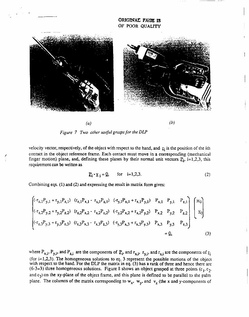
6.0 Conclusion
One factor affecting the acceptability of the DLP which has not been discussed much is how comfortable it is to wear and operate. Presently the 'controls have rings which are custom fitted around the operator's fingers. It may be desirable to make these rings adjustable in diameter and to make them semi-rigid structures. The location of the joint axes of the control mechanisms, as well as the location of the rings themselves also play an important role in the overall comfort of the DLP. An effort is currently underway to provide for more adjustment capability so that one DLP could fit a wide range of hand sizes without any significant re-assembly.
A drawback to the DLP is its somewhat large shroud size (recall, however, that the model shown in the photos is for a large hand size and the author has rather small hands). The main contributor to this condition is the requirement for the shroud to encompass the operator's hand for its full range of motion---another is the space needed for the control mechanisms. The former could be made less of a factor by reducing the ratio of motion of the operator hand to the mechanical hand (and perhaps compensating for the lack of force capability by some sort of power assist). The effect of the latter conhbutor---particularly on the width of the shroud---might be minimized by alternate mechanisms which hopefully place the control joint axes near those of the operator's hand, although the author has not yet concieved of any practical embodiments.
Another area for improvement of the DLP is in its manipulative capability, although the concommitant increase in mechanism complexity may impede this effort for awhile. Assuming ideal three point contact (with no sliding), at least nine independently controlled joints would be needed to impart arbitrary motions to the object---a configuration which is used for the Stanford/JPL Hand [l]. The likely locations for the additional degrees-of-freedom for the DLP would be to add lateral motion capability to each mechanical finger and the thumb. The thumb seems to be the best candidate initially (for a lateral motion capability) since it could, besides improving dexterity, more significantly enhance the number of prehension patterns. Note that the angle of the thumb plane with respect to the finger planes of motion for the DLP was based partly on a study done by Lozach [2], who found that an angle of forty five degrees seemed to be optimum for many tasks.
Preliminary results with the DLP have shown that the device may indeed be useful for EVA'S. Further evaluation will commence after completion of the shroud. The DLP will then be connected to the NASNAmes AX-5 Hard Suit for testing in the Ames neutral bouyancy tank.
7.0 Acknowledgements
This work was sponsered by the NASA Ames research center at Moffet Field, California. The author is especially appreciative of the support and advice of Mr. Vic Vykukal, the NASA Ames technical monitor for the prehensor project, and the support of Dr. Larry Leifer, Principle Investigator for the project at Stanford University.
8.0 References
[ 11 J. K. Salisbury, Kinematic and Force Analysis of Articulated Hands, Ph.D. Dissertation, Dept. of Mechanical Engineering, Stanford University, May, 1982.
[2] Lozach, Y., "The Preferred Working Plane for an Active Thumb," 2nd International Conference on Rehabilitation Engineering, Ottowa, Canada, 1984.
[3] L. Leifer, J. Jameson, M. Leblanc, D. Wilson, E. Sableman, and D. Schwandt, "Design, Development, and Evaluation of an EVA Prehensor," Proc. of the Workshop on Space Telerobotics, Pasadena, California, January 20--22, 1987.

, . ,'r * c
u DESIGN, DEVELOPMENT, and ASSESSMENT of a n EVA PREHENSOR z
PERFORMANCE ASSESSMENT WORKSTATION (PAW) Design S p e c i f i c a t i o n s
D r a f t : August 2 2 , 1986 (.) Douglas schwandt
The Per formance Assessment W o r k s t a t i o n draws on a b a t t e r y of new and e x i s t i n g tests t o compare t h e EVA p r e h e n s o r s , space s u i t g loved hand, a n d human hand, T h e s e t e s t s i n c l u d e : ( A ) s t a n d a r d i z e d human h a n d a s s e s s m e n t tes ts ; (B) N A S A i n - h o u s e a n d c o n t r a c t e d t es t s ; ( C ) U. o f Minnesota Track ing System; ( D ) S t a n f o r d I n s t r u m e n t e d Grasp S t r e n g t h Assessment; and (E) S t a n f o r d F u n c t i o n a l Hand Task Assessment .
A. S t a n d a r d i z e d Human Hand Assessment T e s t s .
1. Minnesota Ra te of Manipula t ion . T h e s e t e s t s u s e a m a t r i x o f r o u n d f l a t b l o c k s i n h o l e s
on a h o r r i z o n t a l s u r f a c e . S e v e r a l t i m e d t e s t s w i t h n o r m a l i z e d . d a t a cover : (1) P l a c i n g ; ( 2 ) Turn ing ; ( 3 ) D i s p l a c i n g ; ( 4 ) One- Hand T u r n i n g a n d P l a c i n g ; a n d (5) Two-Handed T u r n i n g a n d P l a c i n g ,
2. Valpar Component Work Sample 4 . T h i s V a l p a r t i m e d t e s t c o n s i d e r s uppe r e x t r e m i t y
r ange of m o t i o n and hand d e x t e r i t y , a s t h e sub jec t a s s e m b l e s ( w i t h o u t u s i n g t o o l s ) n u t s f rom a t r a y o n t o b o l t s p r o t r u d i n g f rom i n t e r n a l and e x t e r n a l faces of a box ( w i t h round open ing on o n e s i d e f o r i n t e r n a l a c c e s s ) . T h i s t e s t i n v o l v e s t h e u s e of s h o u l d e r , e lbow, w r i s t and f i n g e r s w i t h and w i t h o u t v i s u a l feedback .
3 . B e n n e t t Hand Tool D e x t e r i t y T e s t , I n t h i s t e s t , t h e s u b j e c t a s s e m b l e s n u t s a n d b o l t s
t h r o u g h h o l e s i n v e r t i c a l p l a t e s u s i n g b o t h h a n d s , w i t h a n d w i t h o u t hand t o o l s .
4 . Jamar Dynamometer. C y l i n d r i c a l hand g r a s p s t r e n g t h a s s e s s m e n t a g a i n s t a m e c h a n i c a l s p r i n g guage.
5. Pinch Meter. Pa lmer , L a t e r a l and F i n g e r T i p g r a s p s t r e n g t h is measured on a mechan ica l s p r i n g guage.
B. NASA In-House and Con t rac t ed Tes ts .
c
1. SRI Remote Man ipu la t ion T a s k Board. T h i s t e s t was p e r f o r m e d a s a s t u d y f o r J P L u n d e r
a NASA g r a n t t o compare two r e m o t e m a n i p u l a t o r s w i t h t h e human h a n d i n t h e p e r f o r m a n c e o f b a s i c u n i t t a s k o p e r a t i o n s i n c l u d i n g : Move, T u r n , A p p l y P r e s s u r e , G r a s p , R e l e a s e , Pre- P o s i t i o n , I n s e r t , Disengage, Crank, Con tac t .
2, Space S u i t Glove T e s t . NASA-Ames pe r fo rmed a v a r i e t y of hand
1

. . . .
C.
- t e s t s w i t h a n a s t r o n a u t w e a r i n g a
s p a c e s u i t w i t h t h e h i g h e r g l o v e p r e s s u r e . T h e s e t e s t s ' i n c l u d e d u s e of t h e Work S i m u l a t o r , a n d a r e d o c u m e n t e d i n a NASA v i d e o e n t i t l e d , "ZPS w i t h Don P e t e r s o n a t ILC 9/11/85,
3 . Ease Access T e s t . T h e NASA E a s e Access T e s t i s a s i m u l a t i o n o f s p a c e s t a t i o n a s s e m b l y u s i n g a l a r g e
t r u s s f r a m e ,
Univ. of Minnesota T r a c k i n g System. D e v e l o p e d by J a m e s C a r e y a t t h e U o f M i n n e s o t a , t h e
s y s t e m u s e s a power ( c y l i n d r i c a l ) g r a s p dynamometer t o t r a c k f o r c e a n d a f i n g e r j o i n t g o n i o m e t e r t o t r a c k j o i n t a n g l e , a s a d i a g n o s t i c t o o l a n d a n a s s e s s m e n t t o o l t o m o n i t o r p r o g r e s s i n t h e r a p y , The subjec t m u s t t r y t o f o l l o w a s e t waveform p a t t e r n on a n App le Compute r s c r e e n , The s o f t w a r e c a p t u r e s t h e t r a i l o f j o i n t a n g l e o r f o r c e s u p e r i m p o s e d on t h e t a r g e t t r a c k , a n d t h e n s t a t i s t i c a l l y c o m p u t e s t o f i t . P o s s i b l e t r a c k i n g s t r a t e g i e s i n c l u d e : j o i n t a n g l e , a n g u l a r v e l o c i t y , a n g u l a r a c c e l e r a t i o n , force/moment , m u l t i p l e t a s k or 3d tracking. It is p o s s i b l e t h a t a n i m p o r t a n t m o t i o n w i t h s p e c i f i c v e l o c i t y p r o f i l e may b e u n a t t a i n a b l e w i t h a g l o v e d h a n d o r p r e h e n s o r , a n d t h i s w i l l o b j e c t i v e l y d e m o n s t r a t e a l i m i t a t i o n .
D. S t a n f o r d I n s t r u m e n t e d Grasp S t r e n g t h Assessment . Grasps a r e fund- a m e n t a l t o human
hand i n t e r a c t i o n w i t h t h e envi ronment . P a r t i c u l a r l y i m p o r t a n t t o s p a c e work i s t h e g r a s p i n g o f h a n d r a i l s , c a b l e s , o r b a r s f o r r e o r i e n t a t i o n a n d t r a n s l a t i o n i n s p a c e , a n d t h e g r a s p i n g o f ob- jects f o r m a n i p u l a t i o n .
A JR3 s i x degree-of-freedom f o r c e and moment t r a n s d u c e r i s used t o m e a s u r e m e a s u r e a p p l i e d f o r c e s a n d moment s i n e a c h o f t h e t h r e e o r t h o g o n a l d i r e c t i o n s ( x , y , z ) , f o r e a c h t y p e of g r a s p : ( I ) Hook; ( 2 ) C y l i n d r i c a l ; ( 3 ) S p h e r i c a l ; ( 4 ) T h r e e - J a w C h u c k ; ( 5 ) P a l m e r ; ( 6 ) L a t e r a l ; ( 7 ) F i n g e r T ip ; ( 8 ) S l i p p e r O b j e c t s ; ( 9 ) M u l t i p l e O b j e c t s ; and (9) Hoop g r a s p s .
E. S t a n f o r d F u n c t i o n a l Hand Task Assessment , T h e f o l l o w i n g ' t a s k s r e p r e s e n t t h e b r o a d
s p e c t r u m of hand f u n c t i o n s used i n d a i l y l i v i n g . The p r e m i s e f o r u s e of t h e s e t a s k s i n t h e a s s e s s m e n t o f EVA p r e h e n s o r s i s t h a t t h e u l t i m a t e g o a l i s f o r humans t o f u n c t i o n a s d e f t l y i n s p a c e a s o n e a r t h . A l t h o u g h some of t h e s e t a s k s may n o t r e p r e s e n t t h o s e e x p e c t e d t o be used i n n e a r - f u t u r e s p a c e s t a t i o n s u i t e d work, t h e y s h o u l d p r o v i d e an e x t e n s i v e compar i son of t h e EVA prehenscrrs w i t h t h e h i g h p r e s s u r e g l o v e d h a n d a n d t h e u n h i n d e r e d human hand . P e r h a p s 1 0 o r 1 5 o f t h e f o l l o w i n g t a s k s w i l l be s e l e c t e d a s a r e p r e s e n t a t i v e d u r i n g a n y o n e t e s t i n g p e r i o d . A s i m p l e p o i n t s y s t e m may be used w i t h p a r t i a l c r e d i t g i v e n f o r s u c c e s s f u l com- p l e t i o n o f p o r t i o n s of a t a s k , a s d e f i n e d f o r e a c h t a s k . T a s k s may be chosen from t h e f o l l o w i n g l i s t :
2

Grasp slippery object (soap, marbles, etc) Grasp water baloons of different sizes without puncturing Grasp floating vs. weighted objects for water tests Grasp variety of shaped/weight objects (balls, cylinders, cones,
Grasp "pick-up sticks" Grasp specific colored wires out of bunch of wires Grasp edge and peal-off tape or label Grasp sheet of paper Open and close clothes pin Catch objects (ball or frisbee or bean bag) Pump up blood pressure cuff (and tracking task, squeeze accuracy) Pop a baloon (develop high local pressures or forces) Grasp pulling ropes with varied resistance/friction/size/pinch
grips Passive clamping (toggle mechanism--human hand can clamp pen
woven between fingers without actively using muscles) Scoop up many objects (M&Ms, coins, marbles, etc) Spread rubber bands - weave around objects (replace O-rings) Untangle knot Hand-held calculator hold/operate different size keyboards Air hose connector (and other connectors) Use chopsticks/tweezers (orient two or more objects as a combined
Open/close latches (simple toggles, push and turn latches, etc.) Use keys Hold pencil and write numbers Operate torque wrench to specified torque Move individual joints independently or in various combinations Attach/detach tether hooks Turn knobs Operate levers (pencil sharpener over ctr. cams suction cups) Combination lock to open workstation Squeeze triggers Remove and replace pins Start/turn threaded fastener Hold/position/thread cables Open/close safety pins Orienting puzzle pieces Fan a deck of cards Exchange card from top to bottom with one hand Operate joystick (roller, force, position, velocity, acceleration,
Operate hand tools (screw driver, pliers, vise grips, forceps,
Operate power tools Hold/guide a sliding rope/cable Proprioception tasks (with eyes closed ("groping"), grasp object
off Velcro on clothing, measure finger location/opening, select certain objects out of grab bag, find objects and grasp from in sand, or fluid)
cubes, etc.)
tool or utensile)
joystick with fire button)
wrenches, palm spinner tool to drive screw)
Press thumb tack Stack concentric cylinders Hold different size screws in palm and reorient to use
Physical Shape/Size/Properties:
c 3

* < l b
Cover holes on a flute (pulpyness of digits, and range) Swim in or stir fluids (developable frontal area) Piano key spread Select various piano chords Probe different size openings
(- -l Thermal conductivity Electrical conductivity
Sensing temperature Sensing pressure Surface finish detection (smoothness/roughness)
Cranks/winches (wobble (implicit torques), circular, elliptical) Linear drives (sliding shaft (nail remover)) Turn/spin objects (wing nuts)
Launch Small Objects: Flick object (bottle caps, coins ... holding wrist fixed, furthest Flip coins Controlledangularmomentum- intermediate momentofinertia
Handle Large Objects: Guide large (or certain shape) objects through maze in water/air
Handle large flat panels Balance beach ball on hand - make it spin on finger Juggle two bean bags (requires quick/accurate throw/catch)
Smart hand features
Finger/thumb sweep around another finger/thumb Reach different parts of body
Sign language Star Trek communicator
Static/Dynamic Modeling of Hand: 'Vibration isolation/control (snare drum stick) Analyze dynamics of extended/weighted prehensor, and influence of
Friction tests (use JR3 as force plate between finger grip)
Smoothing/dusting/wiping/clearing surface
Construct "dog house"
Pulling tasks - will hand hold together Fatigue testing - alternating grasps (test fatigue on finger
Determine working load limits Identify stress concentrations Reliability and failure modes Durablility (withstand clamping force on digits) Individual joint torque vs. angular position
Carry full cup of water
Sensation:
Drive Systems:
distance)
(without touching walls)
Sma r t ne s s :
Range of Motion:
Communication: C '
springs, dampening, etc. (using Kane's Dynamics)
Complex Surface Interaction:
Complex Tasks:
Strength Tests:
interfaces)
Balance Tasks:
c 4

LIST of BASIC HAND FUNCTIONS:
(G) Grasp, (GH) Grasp--Hook, (GC) Grasp--Cylindrical,
(GL) Grasp--Lateral, (GF) Grasp--Finger Tip, (GM) Grasp--Minimal-Friction, (GE) Grasp--External-Hoop, (GOP) Gr asp--Mu1 t iple-0bj ects-Precision, (GOS) Grasp--Multiple-Objects-Scoop, (R) Rotate, (T) Translate, (SI Separate, (SM) Smooth, (L) Launch, (C) Catch, (SC) Scrape, (PI Pry, (CHI Chisel, (GU) Guide (moving object through hand (sliding rope)), (RO) Re-Orient (within hand), (I) Insert, (AF) Apply External Force, (AM) Apply External Moment, (PP) Pre-Position, (RE) Release, (CO) Contact, (CR) Crank, (D) Disengage, (PO) Position, (AP) Apply External Pressure (squeeze), (REA) Reach, (MT) Multi-Task, (POK) Poke, (TA) Tap, (LO) Locate, (VF) Visual Feedback, (FF) Force-Feedback, (PF) Position Feedback
j (GS) Grasp--Spherical, (GT) Grasp--Three-Jaw-Chuck, (GP) Grasp--Palmer,
WORKSTATION CONCEPTS: cube, lazy Susan disk, kiosk, tiltable spinning game board, presentation of tasks on working surface/tray, lexan mtl.
COMPUTER: presents a task; records data; analyzes data; compares
SENSORS: Hall Effect (position); voltage comparitors/potentiometers,
hands; graphically simulates hand motion; plans grasps.
etc.
c MEASUREMENTS: strength, dexterity or manipulation (translation, rotation, re-orientation), time (duration), impulse, accuracy, physical dimensions/shape, proprioception, sensation thresholds, associated body dynamics, approach (pronation/supination), hand function before and after using glove/prehensors (fatigue, endurance, sensation, tenderness, and score on std. tests, etc.) repeatability, resolution, work and power output, rxn time, document with photos/video/notes, position, velocity, acceleration, task completion.
CONSIDERATIONS: subject has no posture limitations in performing tasks (standing, seated, kneeling); constraints may be imposed later; second hand may at times help stablized workstation/task, but not participate in primary function (generally); include both fine and gross motor activities friction tests may be difficult to isolate variables; strength-mobility-coordination; segmented protocol; hierarchy of tasks (range): specific basic motions b forces ----- specific tool level tasks --- assembly
ASTRONAUT TASKS for EVA SPACE STATIONS: (from Williams report)
c
Mo bi 1 i ty Translate on handrails Translate on cables [translation speed = 0.5 to 1.0 ft/sec] Control attitude
Hold handrails Stability
5

* b + . a - . Hold handgrips P o s i t i o n f o o t r e s t r a i n t s Operate t e ther hooks
Operate MMU Use j o y s t i c k s Use knobs and levers
Assembly, Se rv ic ing , and Repair Hold, p o s i t i o n , and t h r e a d c a b l e s Plug and unplug connec tors Hold power t o o l s Use manual t o o l s
c3
p l i e r s , d i ags , v i s e g r i p s , f o r c e p s , e tc . s c rewdr ive r s wrenches
Operate manual winch Remove and r e p l a c e p i n s P u s h l a r g e o b j e c t s around Use threaded f a s t e n e r s Handle l a r g e p a n e l s / p l a t e s Squeeze t r i g g e r s F l i p note pad Handle smal l o b j e c t s ( "n i ce b u t no t necessary") Se l f donning ( " n i c e b u t not necessary") Odd ang le g r a s p
c
*.
6