Embed Size (px)
Citation preview

1
“DESIGN & DEVELOPMENT OF A PYROLYSIS
REACTOR”
A THESIS SUBMITTED IN PARTIAL FULFILLMENT
OF THE REQUIREMENTS FOR THE DEGREE OF
BACHELOR OF TECHNOLOGY
IN
MECHANICAL ENGINEERING
BY
RAHUL
Under the Guidance of
Prof. S. Murugan
Department of Mechanical Engineering
National Institute of Technology Rourkela
Rourkela – 769 008

2
National Institute of Technology
Rourkela
CERTIFICATE
This is to certify that the project entitled, “Design & Development of a Pyrolysis
Reactor” submitted by Mr. Rahul in partial fulfillments for the requirements for
the award of Bachelor of Technology Degree in Mechanical Engineering at
National Institute of Technology, Rourkela (Deemed University) is an authentic
work carried out by him under my supervision and guidance.
To the best of my knowledge, the matter embodied in the report has not been
submitted to any other University / Institute for the award of any Degree or
Diploma.
Date:
(Prof. S. Murugan)
Dept. of Mechanical Engineering,
National Institute of Technology
Rourkela - 769008, Orissa

3
ACKNOWLEDGEMENT
I would like to express my deep sense of gratitude to my supervisor, Prof. S
Murugan, for his excellent guidance, suggestions and constructive criticisms and
valuable suggestion throughout this project work.
I would like to express my gratitude to Prof. R.K. Sahoo (Head of the
Department) and Prof. K.P. Maity (Project Coordinator) for their valuable
suggestions and encouragements at various stages of the work. I am also thankful
to all staff & members of Department of Mechanical Engineering, NIT Rourkela.
I greatly appreciate & convey my heartfelt thanks to my colleagues’ flow of
ideas, dear ones & all those who helped me in completion of this work.
NIT Rourkela RAHUL

4
CONTENTS
Page No
Chapter 1 INTRODUCTION 6-14
1.1 FUELS FOR SI ENGINES
1.2 FUELS FOR CI ENGINES
Chapter 2 VEGETABLE OIL & PYROLYSIS OIL 15-26
2.1 VEGETABLE OIL
2.2 PYROLYSIS OIL
2.3 BIOFUEL
Chapter 3 LITERATURE ON PYROLYSIS OIL 27
Chapter 4 DESIGN OF A PYROLYSIS SETUP 28-32
Chapter 5 PYROLYSIS OF WASTE WOOD 33-52
Chapter 6 CONCLUSION 53
Chapter 7 REFERENCES 54-57

5
ABSTRACT
Researchers led by rise in energy demand, stricter emission norms & exhausting oil resources are
in search for an alternative fuel for IC engines. Some alternative fuels such as Alcohols,
Biodiesel, LPG, CNG etc have been in the transport sector on a commercial scale. A renewed
interest has been currently received for the pyrolysis of solid wastes. Simplification of the
disposal of many wastes can be done by pyrolysis to some extent. Analysis of the properties of
the oil derived from wastes was done & compared with the petroleum products. In this paper,
description of the study of using waste pyrolysis oil is being done. The oil has been obtained
from waste substances by the method of vacuum pyrolysis.

6
1. INTRODUCTION
The study of fuels for IC engines has been carried out ever since these engines came into
existence. The engine converts heat energy which is obtained from the chemical combination of
the fuel with oxygen, into mechanical energy. Since the heat energy is derived from the fuel, a
fundamental knowledge of types of fuels & their characteristics is essential in order to
understand the combustion phenomenon. The characteristics of the fuel used have considerable
influence on the design, efficiency, output & particularly, the reliability & durability of the
engine. Further, the fuel characteristics play a vital role in the atmospheric pollution caused by
the engines used in automobiles.
The energy sources available can be divided into 3 types:
1. Primary energy sources:
Primary energy sources can be defined as sources which provide a net supply of energy.
Coal, oil, uranium etc are examples. The energy required to obtain these fuels is much
less than what they can produce by combustion or nuclear reaction. Their energy yield
ratio, which is the energy fed back by the material to the energy received from the
environment is very high. The primary fuels only can accelerate growth but their supply
is limited. It becomes very essential to use these fuels sparingly. Primary fuels contribute
considerably to the energy supply.
2. Secondary fuels:
They produce no net energy. Though it may be necessary for the economy, these may not
yield net energy. Intensive agriculture is an example wherein terms of energy the yield is
less than input.
7
3. Supplementary sources:
These are defined as those whose net energy yield is zero & those requiring highest
investment in terms of energy. Insulation (thermal) is an example for this source.
Coal, natural gas, oil & nuclear energy using breedor reactor are net energy yielders
& are primary sources of energy. Secondary sources are like solar energy, wind energy, water
energy etc.
ENERGY CONSUMPTION AS A MEASURE OF PROSPERITY :
Energy is an important input in all sectors of any country’s economy. The standard of living of a
given country can be directly related to per capita energy consumption. Energy crisis is due to
the two reasons: firstly that the population of world has increased rapidly & secondly the
standard of living of human beings has increased. If we take the annual per capita income of
various countries & plot them against per head energy consumption, it will appear that the per
capita energy consumption is a measure of the per capita income or is a measure of the
prosperity of the nation. The per capita income of developed countries like USA is about 50
times more than per capita income of India & so also is the per capita energy consumption. The
per capita energy consumption in USA is 8000 kWh per year, whereas the same in India is 150
kWh. USA with 7 % of world’s population consumes 32 % of the total energy consumed in the
world, whereas India, a developing country with 20 % of world’s population consumes only 1 %.
Developing countries, at present export primary products such as food, coffee, tea, jute, & ores
etc .This does not give them the full value of their resources. To get better value, the primary
products should be processed to products for export. This needs energy.

8
Conclusions of the study on alternate energy strategies are:
1. The supply of fossil oil will soon fail to meet increasing demand, even if energy prices rise
50% above current levels in real terms. Additional constrains on oil production will hasten this
shortage, thereby reducing the time available for action on alternatives.
2. Demand for energy will continue to grow even if governments adopt vigorous policies to
conserve energy. This growth must increasingly be satisfied by energy resources other than oil,
which will be progressively reserved for uses that fossil oil can satisfy.
3. The continued growth of energy demand requires that energy resources be developed with the
utmost vigor. The change from a world economy dominated by fossil oil must start now. The
alternatives require 5 to 15 years to develop & the need for replacement fuels will increase
rapidly.
It has been concluded that world fossil oil production if likely to level-off very shortly & that
alternative fuels will have to meet growing energy demand. Large investments & long lead times
are required to produce these fuels on a scale large enough to fill the prospective shortage of
fossil oil, the fuel that now furnishes most of the world’s energy. The task for the world will be
to manage a transition from dependence on fossil oil to greater reliance on other alternative fuels.
ENERGY SOURCES & THEIR AVAILABILITY
Today, every country draws its energy needs from a variety of sources. We can broadly
categorize these sources as commercial & non-commercial. The commercial ones include fossil
fuels-coal, oil, natural gas, hydroelectric power, & nuclear power, while the non-commercial
sources include wood, animal waste & agricultural wastes. In an industrialized country like USA,
most of the energy requirements are met from commercial sources, while in an industrially less
developed country like India, the use of commercial & non-commercial sources are about equal.
Wood was dominant source of energy in pre-industrialization era. It gave way to coal & coke.
Use of coal reached a peak in the early part of twentieth century. Fossil oil get introduced at that

9
time & has taken a substantial share from wood * coal. Wood is no more regarded as a
conventional source. Hydroelectricity has already grown to a stable level in most of the
developed countries. A brief account of the various important sources of energy & their future
possibilities is as:-
The percent use of various sources for the total energy consumption in the world is:
Coal 32.5 %
Oil 38.3 %
Gas 19 %
Uranium 0.13 %1
Hydro 2 %
Wood 6.6 %
Dung 1.2 %
Waste 0.3 %
Coal, oil, gas, uranium & hydro are commercial or conventional energy sources. Looking at the
percent distribution, one finds that world’s energy supply comes mainly from fossil fuels. The
heavy dependence on fossil fuels stands out clearly. One of the so most significant aspects of the
current energy consumption pattern in many developing countries is that non-commercial
sources such as firewood, animal dung & agricultural waste represent a significant 8 % of the
total energy used in the world. They constitute about 4 times the energy produced by the hydro &
60 times the energy produced by nuclear sources. In some developing countries non-commercial
energy sources are a significant fraction of the total resources. This dependence of the
developing countries is likely to continue unless replaced by other alternative sources of energy.
Due to the limited fossil oil reserves, India has to depend on substantial imports for meeting its
future requirements. The bulk of the demand for fossil oil is from transport sector, & in order to
reduce the pressure from this sector, it is necessary to explore possibilities of developing
substitute fuels like bio-mass & pyrolysis oils.

10
1.1 FUELS FOR SI ENGINES
Fuels used in IC engines should possess certain basic qualities which are important for the
smooth running of the engines .Gasoline which is mostly used in the present day SI engines is
usually a blend of several low boiling paraffins, naphthalenes & aromatics in varying
proportions. Some of the important qualities of gasoline are:-
(i) Volatility:
Volatility is one of the main characteristic properties of gasoline which determines its suitability
for use in an SI engine. Since gasoline is a mixture of different hydrocarbons, volatility depends
on the fractional composition of the fuel. The usual practice of measuring the fuel volatility is the
distillation of the fuel in a special device at atmospheric pressure & in the presence of its own
vapor. The fraction that boils off at a definite temperature is measured. The characteristic points
are the temperatures at which 10, 40, 50 & 90% of the volume evaporates as well as the
temperature at which boiling of the fuel terminates. The more important aspects of volatility
related to engine fuels are in conjunction with the distillation curve:-

11
(ii) Starting & Warm up:
A certain part of the gasoline should vaporize at the room temperature for easy starting of the
engine. Hence, the portion of the distillation curve between about 0 & 10 % boiled off have
relatively low boiling temperatures. As the engine warms up, the temperature will gradually
increase to the operating temperature. Low distillation temperatures are desirable throughout the
range of the distillation curve for best warm-up.
(iii) Operating Range Performance:
In order to obtain good vaporization of the gasoline, low distillation temperatures are preferable
in the engine operating range. Better vaporization tends to produce both more uniform
distribution of fuel to the cylinders as well as better acceleration characteristics by reducing the
quantity of liquid droplets in the intake manifold.
(iv) Crankcase Dilution:
Liquid fuel in the cylinder causes loss of lubricating oil (by washing away oil from cylinder
walls) which deteriorates the quality of lubrication & tends to cause damage to the engine
through increased friction. The liquid gasoline may also dilute the lubricating oil & weaken the
oil film between rubbing surfaces. To prevent these possibilities, the upper portion of the
distillation curve should exhibit sufficiently low distillation temperatures to ensure that all
gasoline in the cylinder is vaporized by the time the combustion starts.
(v) Vapor Lock Characteristics:
High rate of vaporization of gasoline can upset the carburetor metering or even stop the fuel flow
to the engine by setting up a vapor lock in the fuel passages. This characteristic, demands the
presence of relatively high boiling temperature hydrocarbons throughout the distillation range.
Since this requirement is not consistent with the other requirements desired, a compromise must
be made for the desired distillation temperatures.

12
(vi) Antiknock Quality:
Abnormal burning or detonation in an SI engine combustion chamber causes a very high rate of
energy release, excessive temperature & pressure inside the cylinder adversely affects its thermal
efficiency. Therefore, the characteristics of the fuel used should be such that it resists the
tendency to produce detonation & this property is called its antiknock property. The antiknock
property of a fuel depends on the self-ignition characteristics of its mixture & vary largely with
the chemical composition & molecular structure of the fuel. In general, the best SI engine fuel
will be that having highest antiknock property, since this permits use of higher compression
ratios & thus the engine thermal efficiency & the power output can be greatly increased.
(vii) Gum Deposits:
Reactive hydrocarbons & impurities in the fuel have a tendency to oxidize upon storage & form
liquid & solid gummy substances. The gasoline containing hydrocarbons of the paraffin,
naphthalene & aromatic families forms little gum while cracked gasoline containing unsaturated
hydrocarbons is the worst offender. A gasoline with high gum content will cause operating
difficulties such as sticking valves & piston rings carbon deposits in the engine, gum deposits in
the manifold, clogging of carburetor jets & enlarging of the valve stems, cylinders & pistons.
The amount of gum increases with increased concentrations of oxygen, with rise in temperature,
with exposure to sunlight & also on contact with metals. Gasoline specifications therefore limit
both the gum content of the fuel & its tendency to form gum during storage.
(viii) Sulphur Content:
Hydrocarbon fuels may contain free sulphur, hydrogen sulphide & other sulphur compounds
which are objectionable for several reasons. The sulphur is a corrosive element of the fuel that
can corrode fuel lines, carburetors & injection pumps & it will unite with oxygen to form sulphur
dioxide that, in the presence of water at low temperatures, may form sulphurous acid. Since
sulphur has a low ignition temperature, the presence of sulphur can reduce the self-ignition
temperature, then promoting knock in the SI engine.

13
1.2 FUELS FOR CI ENGINES
(i) Knock Characteristics:
Knock in the CI engine occurs because of an ignition lag in the combustion of the fuel between
the time of injection & the time of actual burning. As the ignition lag increases, the amount of
fuel accumulated in the combustion chamber increases & when combustion actually takes place,
abnormal amount of energy is suddenly released causing an excessive rate of pressure rise which
results in an audible knock. Hence, a good CI engine fuel should have a short ignition lag & will
ignite more readily. Furthermore, ignition lag affects the starting, warm up, & leads to the
production of exhaust smoke in CI engines. The present day measure in the cetane rating, the
best fuel in general, will have a cetane rating sufficiently high to avoid objectionable knock.
(ii) Volatility:
The fuel should be sufficiently volatile in the operating range of temperature to produce good
mixing & combustion.
[Ref 7]
Figure above is a representative distillation curve of a typical diesel fuel.

14
(iii) Starting Characteristics:
The fuel should help in starting the engine easily. This requirement demands high enough
volatility to form a combustible mixture readily & a high cetane rating in order that the self-
ignition temperature is low.
(iv) Smoking & Odour:
The fuel should not promote either smoke or odour in the engine exhaust. Generally, good
volatility is the first prerequisite to ensure good mixing & therefore complete combustion.
(v) Viscosity:
CI engine fuels should be able to flow through the fuel system & the strainers under the lowest
operating temperatures to which engine is subjected to.
(vi) Corrosion & Wear:
The fuel should not cause corrosion & wear of the engine components before or after the
combustion. These requirements are directly related to the presence of sulphur, ash & residue in
the fuel.
(vii) Handling Ease:
The fuel should be a liquid that will readily flow under all conditions that are encountered in
actual use. This requirement is measured by the pour point & the viscosity of the fuel. The fuel
should also have a high flash point & a high fire point.
15
2. VEGETABLE OIL & PYROLYSIS OIL
2.1 VEGETABLE OIL
Bio-diesel, is an alternative for the diesel fuel, that is made from the renewable sources which are
biodegradable like the vegetable oil & the animal fats. It is a biodegradable, non-toxic &
possesses very low emission profiles. It is environmental friendly too.
One hundred years ago, Rudolf Diesel had first tested the vegetable oil as the fuel for his engine.
When cheap petroleum came, crude oil fractions were refined to serve as the fuel & diesel fuels
& diesel engines had started evolving together. Then in the 1940’s, vegetable oils had been used
again as a fuel in emergency times, during the period of World War II. Because of the increase in
crude oil prices, limited resources of fossil fuels & the environmental concern, there had been
renewed focus on vegetable oils & animal fats for production of bio-diesel fuel. Bio-diesel has
potential to reduce level of pollution & level of global warming
Bio-diesel is a mono-alkyl-esters of the long-chain-fatty-acids that are derived from the
renewable lipid sources. Bio-diesel is the name for the variety of the ester based oxygenated fuel
from the renewable biological sources. It could be used in the compression ignition engines with
little or without modifications.
.

16
2.2 PYROLYSIS OILS
Pyrolysis oil is a synthetic fuel. It’s extracted by biomass conversion to liquid by way of
destructive distillation converting dried biomass in the reactor at a temperature of 500°C
followed by cooling. Pyrolytic oil is basically resembles tar and contains very high levels of
oxygen to be called a hydrocarbon. So, this is the reason it’s distinctly different from similar
petroleum products.
Fuel oil characteristics:
The oil produced is an acidic one with a pH of 1.5-3.8 (2.8). The acidity is decreased by addition
of base compounds. The biomass begins with 10% to 15% moisture & the oil obtained doesn’t
end up with water content. Water molecules are split during the pyrolysis & held separately in
other compounds in the pyrolysis liquid. The density is equal to 1.2-1.3 (1.22) kg/l or 10.01-
10.85 (10.18) lbs/gallon, the value of which is much higher than diesel. The oxygen portion is
40-50%, mostly from the water content, & no sulfur is detected normally. The lower heating
value is about 16-21 (17.5) MJ/kg. The pour point is -12°C to -33°C, no cloud point can be
observed uptil -21°C. The carbon residue is 17-23 % wt (0.13% ash). The flash point is 40-
100°C, pyrolysis oil isn’t an auto-igniting one in a CI engine. The cetane number is 10. The
viscosity rises to a max in 12 months owing to polymerization. The pyrolysis oil isn’t stable
reacting with air and degasing. Pyrolysis oil can’t be blended with diesel.

17
2.3 BIOFUELS
Biofuels are the wide variety of fuels which that are derived from the biomasses. It includes
solid biomass, liquid fuels & various biogases. They are gaining more & more public & scientific
attention, due to factors like oil price spikes & the need for increasing energy security.
Bioethanol is basically an alcohol that is made by fermenting sugar components of the plant
materials & it’s made mostly from sugar & starch crops. With the advanced technology under
development, cellulosic biomass, like trees & grasses, are used as feedstocks for production of
ethanol. Ethanol can be used as fuel for the vehicles in the pure form, but it’s used mainly as
gasoline additive to increase the octane & improve the vehicle emissions. Bioethanol is applied
in the USA and in Brazil.
Biodiesel is manufactured from the vegetable oils, the animal fats or recycled greases. Biodiesel
can be used as a fuel for the vehicles in pure form, but it’s used as the diesel additive to decrease
the levels of particulates, carbon monoxide, and the hydrocarbons from diesel-powered vehicles.
Biodiesel is manufactured from the oils or fats by the use of transesterification & is the most
used biofuel in Europe.
Biofuels accounted for 1.8% of world's transport fuel in year 2008. Investments into the biofuels
production exceeded $4 billion in the world in year 2007 and is expanding.
18
3. LITERATURE SURVEY
I.de Marco Rotriguez et al had studied the behaviour & chemical analysis of the pyrolysis oil. In
that work it was reported that Pyrolysis Oil is a complex mixture of organic compounds of 5-20
carbons and with a higher proportion of aromatics. The percentages of aromatics, aliphatic,
nitrogenated compounds, benzothiazol were also determined in the pyrolysis oil at various
operating temperatures of the pyrolysis process. Roy et al.,conducted experiments on the
vacuum pyrolysis. In this work, a step-by-step approach has been used, starting from bench-scale
batch systems, to a process development unit & lastly a pilot plant, to experiment & develop
vacuum pyrolysis of waste wood. It had been reported that the yield is 55% oil, 25% carbon
black, 9% steel, 5% fiber and 6% gas. Adrian M. Cunliffe and Paul T. Williams (1998), had
studied the composition of oils derived from the batch pyrolysis of wastes in a nitrogen purged
static-bed batch reactor, which is used to pyrolyse 3 kg of shredded wastes at temperatures
between 450°C and 600°C. It had been reported that the pyrolysis of wastes produced oil similar
in properties to a light fuel oil, with similar calorific value, sulphur & nitrogen contents. The oil
had been found to contain 1.4 % sulphur and 0.45 % nitrogen on mass basis & have similar fuel
properties to those of diesel fuel. These oils contained significant concn. of polycyclic aromatic
hydrocarbons some of which had been shown to be either carcinogenic and or mutagenic. A
single oil droplet combustion study had been carried out & also the oil was analysed in detail for
its content of polycyclic aromatic hydrocarbons (PAH). The derived oil had been combusted in
an 18.3 kW ceramic-lined, oil-fired, spray burner furnace, 1.6 m in length and 0.5 m internal
diameter. Isabel de Marco Rodriguez et al., (2001) had studied the behavior and chemical
analysis of wastes pyrolysis oil. In the same work, an automatic distillation test was carried out at
500 deg. C to analyse the potential use of waste wood pyrolysis oil as petroleum fuels.

19
4. DESIGN OF A PYROLYSIS SETUP
Desirable parameters for the design:
a) Melting point of the substance
If mp is high, substance easily vaporizes & more oil is obtained.
b) Density
If density is lower, substance easily vaporizes & more oil is obtained.
c) Quality of substance
More is quality, more is the yield of oil.
d) Moisture content
More is moisture, less is the oil yield.
e) Reactor Temp
More is the reactor temp, more is the yield
f) Heating rate
More is the heating rate, more is the yield
g) Reactor size
There is an optimum for the reactor size to get maximum oil yield.
h) Feed rate
Feed rate is given according to the demand for the oil.

20
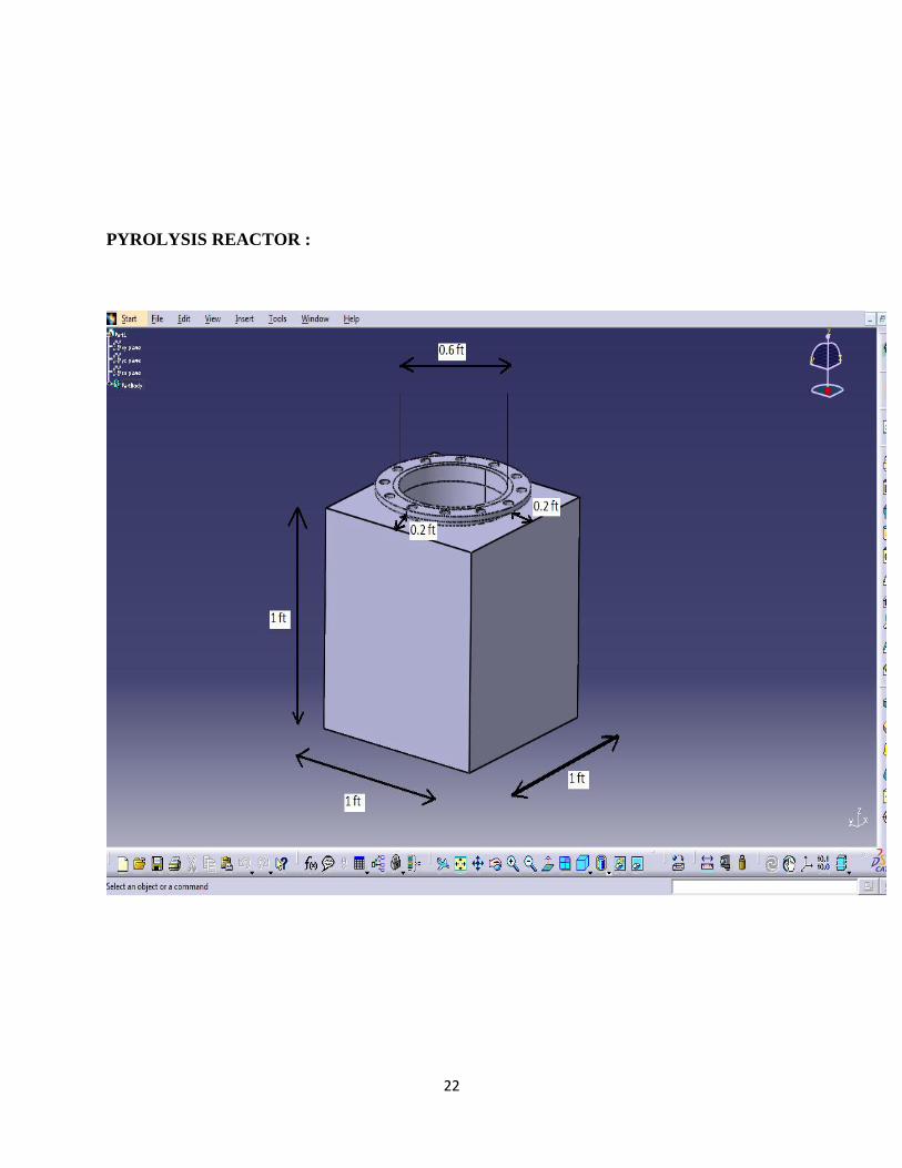
DESIGN SPECIFICATIONS:
Furnace outer dimensions: 1ft x 1ft x 1ft
Diameter of Central Cylindrical Core Heater: 0.6 ft
Height of Central Cylindrical Core Heater: 1 ft
Distance of the heater from the furnace bottom: 0.05 ft
Height of the heater above the furnace top: 0.05 ft
Total Height of the heater: 1 ft
Length of the condenser pipe from reactor top to inlet of condenser: 2 ft
Diameter of condenser: 1 ft
Length of condenser: 1.2 ft
Length of condenser exit to oil collector: 1 ft
21
22
PYROLYSIS REACTOR :

23
CENTRAL CORE HEATER :

24
5. PYROLYSIS OF WASTE WOOD

25
Product Distributions as a Function of Pyrolysis Reactor Temperature:
Outside Reactor Temp (°C)
Gas% Oil% Char, %
300 7 41 52
400 11 51 38
500 16 56 28
600 32 42 26

26
Elemental Composition of Oil:
Elemental composition (wt %)
Proximate analysis (Dry air wt %)
Carbon : 85 Volatile matter : 62
Hydrogen : 12 Fixed carbon : 24
Oxygen : - Moisture content : 1%
Nitrogen : 0.8 Ash content : 13
Sulphur : 2.2
Total : 100.00 : 100.00

27
Properties:
Property Diesel
Crude WPO DWPO10 DWPO20
Density@15
deg C (kg/m3)
830 920 839 848
Kinematic
Viscosity@40
deg C(cSt)
3.2 6.8 3.56 3.92
Calorific Value
(MJ/kg)
46.5 36 45.5 44.4
Flash Point
(deg C)
50 55 50.5 51
Fire Point
(deg C)
56 62 56.6 57.2
Sulphur
Content, %
0.045 0.1 0.05 0.056
Ash Content,% 0.01 - - -
Carbon
Residue,%
0.35 - - -
Aromatic
Content,%
26 - - -

28
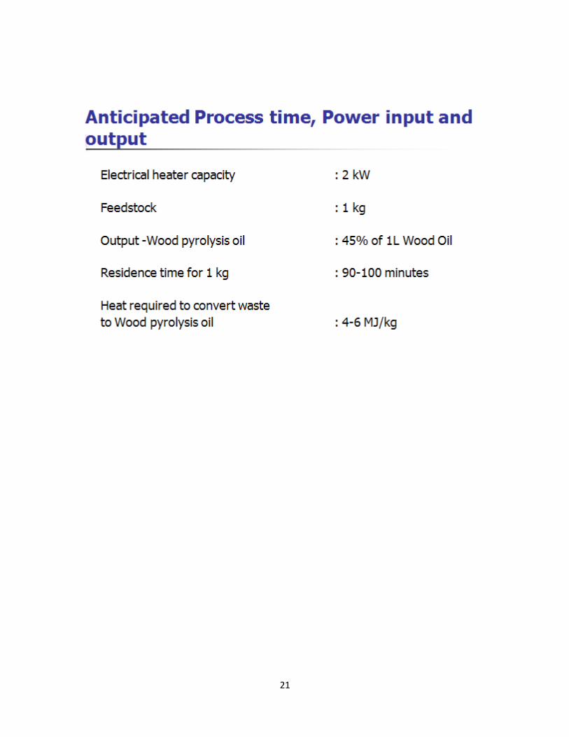
PROCESS TIME, POWER INPUT & OUTPUT
Electrical heater capacity : 2 kW
Feedstock : 1 kg
Output -Wood pyrolysis oil : 0.414 litres
Residence time for 1 kg : 95 minutes
Heat required to convert waste
to Wood pyrolysis oil : 5.3 MJ/kg

29
EXPERIMENTAL SETUP AND PROCEDURE
DIAGRAM
30
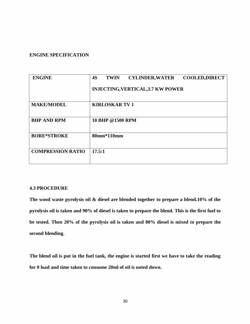
ENGINE SPECIFICATION
ENGINE 4S TWIN CYLINDER,WATER COOLED,DIRECT
INJECTING,VERTICAL,3.7 KW POWER
MAKE/MODEL KIRLOSKAR TV 1
BHP AND RPM 10 BHP @1500 RPM
BORE*STROKE 80mm*110mm
COMPRESSION RATIO 17.5:1
4.3 PROCEDURE
The wood waste pyrolysis oil & diesel are blended together to prepare a blend.10% of the
pyrolysis oil is taken and 90% of diesel is taken to prepare the blend. This is the first fuel to
be tested. Then 20% of the pyrolysis oil is taken and 80% diesel is mixed to prepare the
second blending.
The blend oil is put in the fuel tank, the engine is started first we have to take the reading
for 0 load and time taken to consume 20ml of oil is noted down.

31
DIESEL
Load
(Kgf)
Engine speed (rpm)
Time (sec.)
Ex. temp.
(°c)
Fuel consumption
(Kg/hr.)
Brake power (Kw)
Brake sp. Fuel consumption (Kg/Kw hr.)
Indicated power (Kw)
mechanical
( BP/IP) (%)
thermal
(%) sp
energy
consu-
mption
bsec
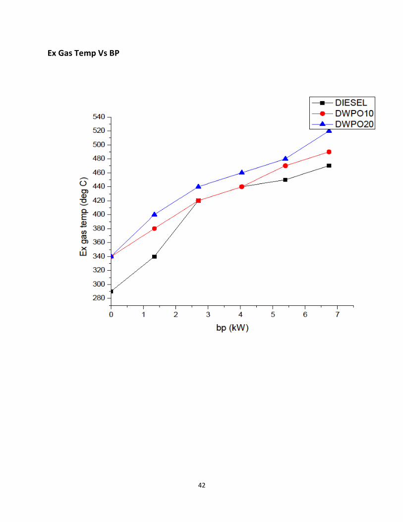
0 1500 74 290 0.81 0 0 4.7 0 0
5 1500 54 340 1.11 1.34 0.828
6.04 22.2 9.3 10.7
10 1500 45 420 1.33 2.7 0.492 7.4 36.5 15.7 6.35
15 1500 39 440 1.53 4.04 0.379 8.74 46.2 20.4 4.9
20 1500 33 450 1.81 5.39 0.336 10.1 53.4 23 4.34
25 1500 27 470 2.21 6.74 0.328 11.4 58.9 23.6 4.24

32
10DWPO-10% Blended Distilled Wood Pyrolysis Oil
Load
(Kgf) Engine speed (rpm)
Time (sec.)
Ex. temp.
(°c)
Fuel consumption
(Kg/hr.)
Brake power (Kw)
Brake sp. Fuel consumption (Kg/Kw hr.)
Indicated power (Kw)
mechanical
( BP/IP) (%)
thermal
(%) sp
energy
consu-
mption
bsec
0 1500 71 340 0.85 0 0 4.5 0 0
5 1500 52 380 1.16 1.34 0.823
5.84 22.9 9.15 10.4
10 1500 43 420 1.4 2.7 0.519 7.2 37.5 15.28 6.55
15 1500 37 440 1.65 4.04 0.408 8.54 47.3 19.39 5.16
20 1500 31 470 1.92 5.39 0.356 9.9 54.4 22.23 4.5
25 1500 26 490 2.29 6.74 0.34 11.24 59.96 23.31 4.3

33
20DWPO-20% Blended Distilled Wood Pyrolysis Oil
Load (Kgf)
Engine speed (rpm)
Time (sec.)
Ex. temp.
(°c)
Fuel consumption
(Kg/hr.)
Brake power (Kw)
Brake sp. Fuel consumption (Kg/Kw hr.)
Indicated power (Kw)
mechanical
( BP/IP) (%)
thermal
(%) sp
energy
consu-
mption
bsec
0 1500 69 340 0.88 0 0 4.4 0 0
5 1500 50 400 1.22 1.34 0.91
5.74 23.34 8.9 11.22
10 1500 41 440 1.49 2.7 0.552 7.1 38.03 14.69 6.81
15 1500 34 460 1.8 4.04 0.445 8.44 47.87 18.24 5.49
20 1500 29 480 2.1 5.39 0.39 9.79 55.06 20.81 4.81
25 1500 24 520 2.54 6.74 0.377 11.14 60 21.51 4.65
34
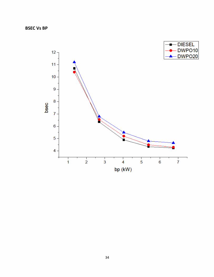
BSEC Vs BP

35
BSEC Vs BP

36
BSFC Vs BP

37
BSFC Vs BP

38
Th. Efficiency Vs BP

39
Th. Efficiency Vs BP

40
Mech Efficiency Vs BP

41
Mech Efficiency Vs BP
42
Ex Gas Temp Vs BP

43
Ex Gas Temp Vs BP

44
6. CONCLUSION
a)20 % blended oil consumes highest specific energy for same bp
b)As blending increases, fuel consumption increases for same bp
c)As blending increases, thermal efficiency decreases for same bp
d)As blending increases, mechanical efficiency increases for same bp
e)As the blending increases, exhaust gas temp increases for same bp

45
7. REFERENCES
[1] G. D. Rai, Non-Conventional Sources of Energy, Khanna Publishers-2004
[2] V. Ganesan, Internal Combustion of Engines, Tata McGraw-Hill Companies, 2008.
[3] S. Murugan, M.C. Ramaswamy, G. Nagarajan, Assessment of pyrolysis oil as an energy source
for diesel engines, Elsevier (2008)
[4] S. Murugan, M.C. Ramaswamy, G. Nagarajan, A comparative study on the performance,
emission and combustion studies of a DI diesel engine using distilled tyre pyrolysis oil–diesel
blends, Elsevier (2008)
[5] S. Murugan, M.C. Ramaswamy, G. Nagarajan, Performance, emission and combustion
studies of a DI diesel engine using Distilled Tyre pyrolysis oil-diesel blends, Elsevier (2008)
[6] S. Murugan, M.C. Ramaswamy, G. Nagarajan, The use of tyre pyrolysis oil in diesel engines,
Elsevier (2008)
[7] A. Sarioglan, H. Olgun, M. Baranak, A. Ersoz, H. Atakul and S. Ozdogan,
Diesel evaporation as the first step of hydrogen production, Elsevier (2007)
[8] http://en.wikipedia.org/wiki/Biofuel
[9] http://en.wikipedia.org/wiki/Pyrolysis_oil
[10] C. Roy, B. Labrecque, B. De Caumia, Recycling of scrap tyres to oil and carbon black by
vacuum pyrolysis. Resources, Conservation and Recycling 4 (1990) 203–213.
[11] S. Mirmiran, H. Pakdel, C. Roy, Characterization of used tire vacuum pyrolysis oil:
nitrogenous compounds from the naphtha fraction, Journal of Analytical and Applied Pyrolysis
22 (1992) 205–215.
[12] Chaala, C. Roy, Production of coke from scrap tire vacuum pyrolysis oil, Fuel Processing
Technology 46 (1996) 227–239.
[13] Napoli, Y. Soudais, D. Lecomte, S. Castillo, Scrap tyre pyrolysis: are the effluents valuable
products, Journal of Analytical and Applied Pyrolysis 40/41 (1997) 373–382.
[14] P.T. Williams, R.P. Bottrill, A.M. Cunliffe, Combustion of tyre pyrolysis oil, IChemE 76 (1998)
291–301.
[15] I. de Marco Rodriguez, M.F. Laresgoiti, A. Cabrero, Torres, M.J. Chomon, B. Caballero,
Pyrolysis of scrap tyres, Fuel Processing Technology 72 (2001) 9–22.
[16] A.A. Zabaniotou, Stavropoulos, Pyrolysis of used automobile tires and residual char
utilization, Journal of Analytical and Applied Pyrolysis 70 (2) (2003) 711–722.
[17] Ozlem Onay, Influence of pyrolysis temperature and heating rate on the production of bio-
oil and char from safflower seed by pyrolysis using a well-swept fixed-bed reactor, Fuel
Processing Technology 88 (5) (2007) 523–531.

46
[18] S. Frigo, R. Gentil, L. Tognotti, S. Zanforlin, G. Benelli, Feasibility of using flash wood
pyrolysis oil in diesel engines, SAE Paper No. 962529, 1996, pp. 165–173.
[19] C. Bertolli, D'Alessio, N. Del Giacomo, M. Lazzaro, P. Massoli, V. Moccia, Running Light duty
DI diesel engines with wood pyrolysis oil, SAE Paper 2000-01-2975, 2000, pp. 3090–3096.
[20] Farid Nasir, Md. Kawser Jamil, Pyrolysis rubber oil as an alternative renewable fuel in diesel
engines, Proceedings of Fifth Asia Pacific International Symposium on Combustion and Energy,
China, 1999, pp. 38–43.
[21] S. Murugan, M.C. Ramaswamy, G. Nagarajan, Production of tyre pyrolysis oil from waste
automobile tyres, In the Proceedings of National Conference on Advances in Mechanical
Engineering, 2006, pp. 899–906.
[22] Yoshiyuki Kidoguchi, Changlin Yang, Ryoji Kato, Kei Miwa, Effects of fuel cetane number
and aromatics on combustion process and emissions of a direct injection diesel engine, JSAE,
Review 21 (2000) 469–475.
[23] J.B. Heywood, Internal Combustion Engines Fundamentals, McGraw Hill, New York, 1998,
pp. 49–667.
[24] G. Nagarajan ,, S Renganayanan, A.N. Rao, Emission and performance characteristics of
neat ethanol fuelled DI diesel engine, International Journal of Ambient Energy 23 (No. 3)
(2002) 149–158.
[25] V. Pradeep, R.P. Sharma, Evaluation of performance, emission and combustion parameters
of a CI engine fuelled with biodiesel from rubber seed oil and its blends, SAE Paper
No. 2005 26-353, 2005, pp. 339–352. [26] J.P. Holman, Experimental Techniques, Tata McGraw
Hill Publications, 2003.
[27] Williams PT et al. Combustion of tyre pyrolysis oil. IChemE 1998;76:291–301.
[28] Zabaniotou AA, Stavropoulos G. Pyrolysis of used automobile tires and residual char
utilization. J Anal Appl Pyrol 2003;7(2):711–22.
[29] Isabel de Marco Rodriguez et al. Pyrolysis of scrap tyres. Fuel Process Technol 2001;72:9–
22.
[30] Frigo S et al. Feasibility of using flash wood pyrolysis oil in diesel engines. SAE 1996; paper
no. 962529. p. 165–173. [31] Bertoli C et al. Running light duty DI diesel engines with wood
pyrolysis oil. SAE paper no. 2000-01-2975. p. 3090–96.
[32] Murugan S, Ramaswamy MC, Nagarajan G. Running a diesel engine with higher
concentration TPO-DF. In: Proceedings of the National conference of research scholars in
mechanical engineering, IIT Kanpur; 2007.
[33] Bhandodaya Reddy G, Reddy KV, Ganesan V. Utilisation of non edible oil in diesel engine.
In: Proceedings of national conference in I.C engines; 2001. p. 211–16.
[34] Nagarajan G, Renganarayanan S, Rao AN. Emission and performance characteristics of neat
ethanol fuelled DI diesel engine. Int J Ambient Energy 2002;23(3):149–58.

47
[35] Kidoguchi Yoshiyuki. Effects of fuel cetane number and aromatics on combustion process
and emissions of a direct injection diesel engine. JSAE 2000;21:469–75. [36] Heywood JB.
Internal combustion engines fundamentals. McGraw Hill Publications; 1988.
[37] Lu Xing-cai et al. Effect of cetane number improver on heat release rate and emissions of
high speed diesel engine fueled with ethanoldiesel blend fuel. J Fuel 2004;83(14–15):2013–20.
[38] Williams PT et al. Combustion of tyre pyrolysis oil. IChemE 1998;76:291–301.
[39] Zabaniotou AA, Stavropoulos G. Pyrolysis of used automobile tires and residual char
utilization. J Anal Appl Pyrol 2003;7(2):711–22.
[40] Isabel de Marco Rodriguez et al. Pyrolysis of scrap tyres. Fuel Process Technol 2001;72:9–
22.
[41] Frigo S et al. Feasibility of using flash wood pyrolysis oil in diesel engines. SAE 1996; paper
no. 962529. p. 165–173.
[42] Bertoli C et al. Running light duty DI diesel engines with wood pyrolysis oil. SAE paper no.
2000-01-2975. p. 3090–96.
[43] Murugan S, Ramaswamy MC, Nagarajan G. Running a diesel engine with higher
concentration TPO-DF. In: Proceedings of the National conference of research scholars in
mechanical engineering, IIT Kanpur; 2007.
[44] Bhandodaya Reddy G, Reddy KV, Ganesan V. Utilisation of non edible oil in diesel engine.
In: Proceedings of national conference in I.C engines; 2001. p. 211–16.
[45] Nagarajan G, Renganarayanan S, Rao AN. Emission and performance characteristics of neat
ethanol fuelled DI diesel engine. Int J Ambient Energy 2002;23(3):149–58.
[46] Kidoguchi Yoshiyuki. Effects of fuel cetane number and aromatics on combustion process
and emissions of a direct injection diesel engine. JSAE 2000;21:469–75.
[47] Heywood JB. Internal combustion engines fundamentals. McGraw Hill Publications; 1988.
[48] Lu Xing-cai et al. Effect of cetane number improver on heat release rate and emissions of
high speed diesel engine fueled with ethanoldiesel blend fuel. J Fuel 2004;83(14–15):2013–20.
[49]. Adrian.M.Cunnliffe, Williams.P.T, 1998, Journal of Applied and Analytical Pyrolysis, 44,
131-152.
[50]. Anthony V. Bridgwater, (2004), Biomass Fast Pyrolysis, Journal of Thermal Science, 8, (2),
21-49.
[51]. Bertoli, C., D’Alessio, Del Giacomo, N., Lazzaro, M., Massoli,P., and Moccia, V., 2000,
Running Light duty DI Diesel Engines with Wood Pyrolysis Oil, SAE paper 2000-01-2975,
pp.3090-3096.
[52]. Chaala and Roy.C, 1996, Production of Coke From Scrap Tire Vacuum Pyrolysis Oil, Journal
of Fuel Processing Technology, 46, 227-239.
11
[53]. David Chiaramonti, Anja Oasmaa and Yrjö Solantausta, 2007, Power Generation Using Fast
Pyrolysis Liquids From Biomass, Renewable and Sustainable Energy Reviews, Vol. 11, Issue 6,

48
1056-1086.
[54]. Frigo, S., Gentil. R.L., Tognotti, 1996, Feasibility of Using Flash Wood Pyrolysis Oil in Diesel
Engines, SAE paper No.962529, 165-173.
[55]. Heywood, J.B, 1988, Internal Combustion Engines Fundamentals, McGraw Hill, New York,
491-667.
[56]. I de Marco Rotriguez, Laresgoiti.M.F, Carbero, M.A., Torres.A, Chomon. M.J., Caballero. B.,
2001, Pyrolysis of Scrap Tyres, Fuel Processing Technology, 72, 9-22.
[57]. Merchant, A.A., and Petrich, M.A., 1993, Pyrolysis of Scrap Tires and Conversion of Chars
to Activated Carbon. American Institute Chemical Engineering Journal, 39, 1370-1376.
[58].Murugan, S., Ramaswamy, M.C., Nagarajan, G., 2006, Production of Tyre Pyrolysis Oil from
Waste Automobile Tyres, In the Proceedings of National conference on Advances in Mechanical
Engineering, 899-906.
[59].Nagarajan., Rao, A.N and Renganarayanan,S., 2002, Emission and Performance ,
Characteristics of Neat Ethanol Fuelled DI Diesel Engine, International Journal of Ambient
Energy, 23, (3),149-158.
[60].Napoli, Y., Soudais, D. Lecomte and Castillo, S., 1997, Scrap Tyre Pyrolysis: Are the Effluents
Valuable Products, Journal of Analytical and Applied Pyrolysis, 40/41, 373-382.
[61].Ozlem Onay, 2007, Influence of Pyrolysis Temperature and Heating Rate on the Production
of Bio- Oil and Char from Safflower Seed by Pyrolysis, Using a Well-Swept Fixed-Bed Reactor,
Fuel Processing Technology, 88, (5), 523-531.
[62].Suat Ucara, Selhan Karagoza, Ahmet R. Ozkanb, Jale Yanikc,*, 2005,Evaluation of two
different scrap tires as hydrocarbon source by pyrolysis, Journal of Fuel, 84 ,1884–1892.
[63].Teng, T., Serio, M.A., Wójtowicz, M.A., Bassilakis,R., and Solomon, P.R., 1995, Reprocessing
of Used Tires into Activated Carbon and Other Products, Journal of Industrial and Engineering
Chemistry Research , 34 (9), 3102-3111.
[64].Yoshiyuki Kidoguchi, Changlin Yang, Ryoji Kato, Kei Miwa, 2000, Effects of Fuel Cetane
Number and Aromatics on Combustion Process and Emissions of a Direct Injection Diesel
Engine, JSAE, Review 21, 469-475.
[65].Yrjo Solantausta, Nils-Olof Nylund, Mfirten Westerholm, Tiina Koljonen and Anja Oasmaa,
1993 , Wood-Pyrolysis Oil as Fuel in a Diesel-Power Plant , Bioresource Technology , 46, 177-
188.
[66] Yu, C.W,.Bari.S, A.Ameena.,2002, Comparison of Combustion Characteristics of Waste
Cooking Oil with Diesel, I Mech E., Proceedings of Institution of Mechanical Engineers, 216, Part
D:J,Automobile,
237-243.
[67].Zabaniotou. A.A., and. Stavropoulos, 2003, Pyrolysis of Used Automobile Tires and Residual
Char Utilization, Journal of Analytical and Applied Pyrolysis, Vol.70, Issue 2, 711-722.

49

50

51

52