Embed Size (px)
Citation preview
ii
ti PROCUREMENT EXECUTIVE, MINISTRY OF DEFENCE
AERONAUTKAL RESEARCH COUNCIL
CURRENT PAPERS
Design Development of an Aircraft Strut in Carbon Fibre
Reinforced Plastic by
T. A. Colhngs
Structures Dept., R.A.E., Farnborough
LONDON: HER MAJESTY’S STATIONERY OFFICE
1972
PRICE f/ NET

UDC 629.13.012.563 : 621-23 : 661.66-426 : 678.046
CP No.1229 *
February 1972
DESIGN DEVELOPMENT OF AN AIRCRAFl' STRUT
IN CARBON FIBRE REINFORCED PLASTIC
T. A. Callings
SUMMARY
An actuator reaction strut from the VC IO aileron power control circuit,
made from steel, has been redoslgned, made and tested in carbon fibre reinforced
plastic (CFRP) with aluminium alloy ends, partly to demonstrate the weight
saving potential of CFRP in this type of application and partly to investigate
some of the problems of jointing and load diffusion which CFRP presents.
The strut has overall axial strength and stiffness requirements in both
tension and compression. All have been met with the redeslgned CFRP strut with
the exception of tensile stiffness, the low value of which was shown to be
fundamental to the form of end attachment adopted.
This Report describes the design, fabrication and testing of the CFRP
strut which weighed 43% less than the original steel component.
* Replaces RAE Technical Report 72032 - ARC 33853
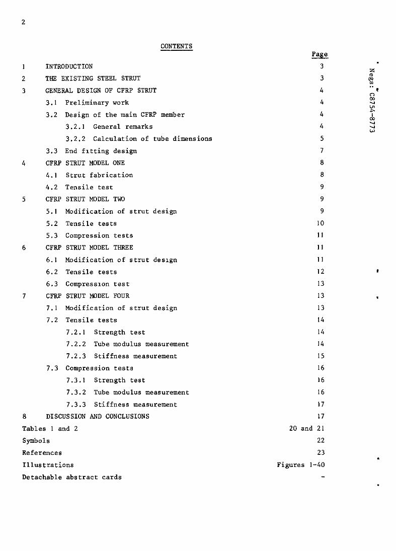
CONTENTS
INTRODUCTION THE EXISTING STEEL STRUT GENERAL DESIGN OF CFRP STRUT 3.1 Preliminary work 3.2 Design of the main CFRP member
3.2.1 General remarks 3.2.2 Calculation of tube dimensions
3.3 End fitting design CFRP STRUT MODEL ONE 4.1 Strut fabrication 4.2 Tensile test CFF.P STRUT MODEL TWO
5.1 Modification of strut design 5.2 Tensile tests 5.3 Compression tests CFRP STRUT MODEL THREE 6.1 Modification of strut design 6.2 Tensile tests 6.3 Compression test CFRP STRUT MODEL FOUR 7.1 Modification of strut design 7.2 Tensile tests
7.2.1 Strength test 7.2.2 Tube modulus measurement 7.2.3 Stiffness measurement
7.3 Compression tests 7.3.1 Strength test 7.3.2 Tube modulus measurement 7.3.3 Stiffness measurement
DISCUSSION AND CONCLUSIONS
Tables 1 and 2 Symbols References Illustrations Detachable abstract cards
w 3 3 4 4 4 4
5 7 8 a 9 9 9
10 11
11 11 12 13 13 13 14 14 14 15 16 16 16 17 17
20 and 21 22
23 Figures l-40
3
1 INTRODUCTION
Carbon fibre reinforced plastic (CFRP) has provided structural engineers
and designers in the aerospace industry with a material of great potential.
The combination of low density and high strength and stiffness promises very
substantial structural weight savings if the novel problems of design and
fabrication can be solved. The exercise described in this Report was one of a
number of early experimental investigations aimed partly at demonstrating the
weight savings which could be shown on paper, and partly at contributing to the
solution of some of these novel problems.
A VC IO aileron control strut was chosen for redesign for a number of
reasons: the loads are highly directional and thx invites the use of CFRP in
the highly anisotropic form in which most weight is likely to be saved; the
component was shorter than the longest carbon fibres then available (I m);
fabrication by moulding from dry fibres and resin was feasible, there being no
pre-impregnated CFRP sheet or tape at that time; the problems of end design
and load transfer were of general interest.
Details of the design, fabrication and testing of the CFRP strut and its
end attachments are given here. The limitations of the design are discussed
and suggestions for possible alternatives are given.
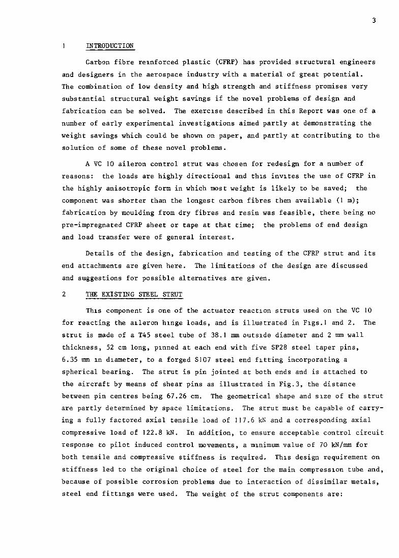
2 THE EXISTING STEEL STRUT
This component is one of the actuator reactlon struts used on the VC IO
for reacting the arleron hinge loads, and is illustrated in F1gs.l and 2. The
strut is made of a T45 steel tube of 38.1 mm outslde diameter and 2 mm wall
thickness, 52 cm long, plnned at each end with five SP28 steel taper pins,
6.35 mm m dxameter, to a forged S107 steel end fitting incorporating a
spherical bearing. The strut is pin jointed at both ends and is attached to
the aircraft by means of shear pins as illustrated in Fig.3, the distance
between pin centres being 67.26 cm. The geometrical shape and sxe of the strut
are partly determined by space limitations. The strut must be capable of carry-
ing a fully factored axial tensile load of 117.6 kN and a corresponding axial
compressive load of 122.8 kN. In addition, to ensure acceptable control circuit
response to pilot induced control movements, a mlnimum value of 70 kN/mm for
both tensile and compressive stiffness is required. This design requirement on
stiffness led to the original choice of steel for the main compresswn tube and,
because of possible corrosion problems due to interaction of dissimilar metals,
steel end fittings were used. The weight of the strut components are:
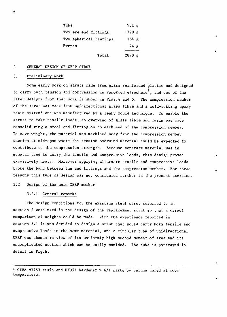
Tube 952 g Two eye end fittings 1720 g
Two spherical bearings 154 g Extras 44 g
Total 2870 g
3 GENERAL DESIGN OF CFRP STRUT
3.1 Prelminary work
Some early work on struts made from glass reinforced plastw and designed to carry both tensmn and compression is reported elsewhere', and one of the later designs from that work is shown in Figs.4 and 5. The compression member of the strut was made from unidirectional glass fibre and a cold-setting epoxy resm system* and was manufactured by a leaky mould technique. To enable the struts to take tensile loads, an overmnd of glass fibre and resin was made consolidating a steel end fittmg on to each end of the compression member. To save weight, the material was machined away from the compression member section at mid-span where the tenslon overwind material could be expected to contribute to the compression strength. Because separate material was in general used to carry the tensile and compressive loads, this design proved excessively heavy. Moreover applying alternate tensile and compressive loads broke the bond between the end flttlngs and the compressxon member. For these reasons this type of design was not considered further in the present exercue.
3.2 Design of the man CFRP member
3.2.1 General remarks
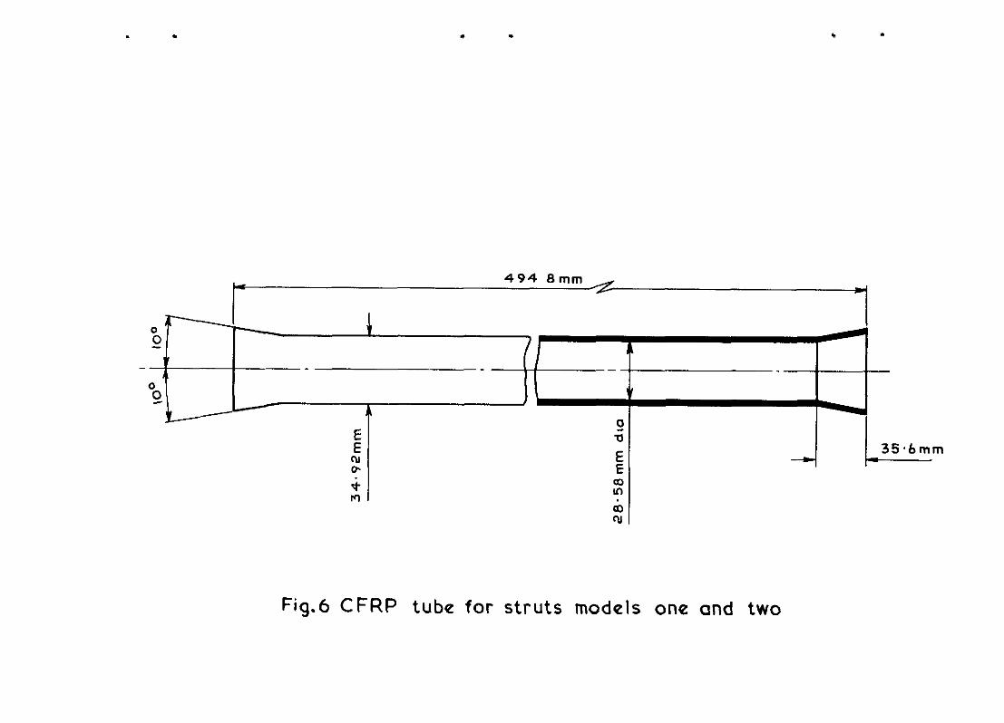
The design conditions for the existing steel strut referred to in sectlon 2 were used in the design of the replacement strut so that a direct comparison of weights could be made. With the experience reported in sectlon 3.1 it was declded to design a strut that would carry both tensile and compressive loads in the same material, and a circular tube of unidirectional CFRP was chosen 1~1 view of its uniformly high second moment of area and its uncomplicated sectlon which can be easily moulded. The tube is portrayed in
detail in Fig.6.
* CIBA MY753 resin and HY951 hardener 2, 6/l parts by volume cured at room temperature.
5
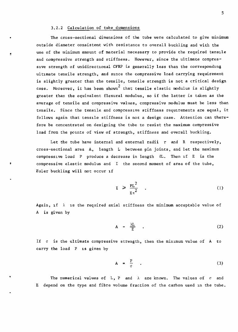
3.2.2 Calculation of tube dmensions
The cross-sectional dimensions of the tube were calculated to give minimum
outside diameter consistent with resistance to overall buckling and with the
use of the minimum amount of material necessary to provide the required tensile
and compressive strength and stiffness. HOWaVar, since the ultimate compres-
save strength of unidirectional CFRP is generally less than the correspondlng
ultimate tensile strength, and sxnce the compressive load carrying requirement
is slightly greater than the tensile, tensile strength is not a critical design
case. Moreover, it has been shown' that tensile elastic modulus is slightly
greater than the equivalent flexural modulus, so if the latter is taken as the
average of tensile and compressive values, compressive modulus must be less than
tensile. Since the tensile and compressive stiffness requrements are equal, it
follows again that tensile stiffness is not a design case. Attention can there-
fore be concentrated on designing the tube to resist the maximum compressive
load from the points of view of strength, stiffness and overall buckling.
Let the tube have internal and external radii r and R respectively,
cross-sectional area A, length L between pin joints, and let the maximum
compress~va load P produce a decrease in length 6L. Then If E is the
compressive elastic modulus and I the second moment of area of the tube,
Euler buckling will not occur If
.
.
1 2 PL2 - . ET2
(I)
Again, If X 1s the required axial stiffness the minimum acceptable value of
A is given by
A = & E * (2)
If D is the ultimate compressive strength, then the minunum value of A to
carry the load P 1s given by
(3)
The numerical values of L, P and i are known. The values of o and
E depend on the type and fibre volume fraction of the carbon used xn the tube.
6
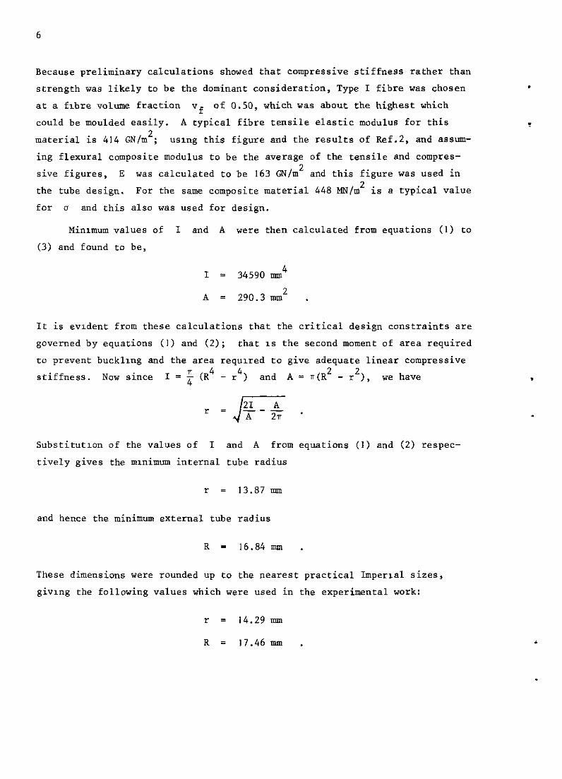
Because preliminary calculations showed that compressive stiffness rather than strength was likely to be the dominant consideration, Type I fibre was chosen at a fibre volume fraction vf of 0.50, which was about the highest which
could be moulded easily. A typical fibre tensile elastic modulus for this
material is 414 GN/m'; usmg this figure and the results of Ref.2, and assm- ing flexural composite modulus to be the average of the tensile and compres- sive figures, E was calculated to be 163 @J/m2 and this figure was used in the tube design. For the same composite material 448 MN/m2 is a typical value for Cl and this also was used for design.
Minmmm values of I and A were then calculated from equations (I) to (3) and found to be,
I = 34590 imu4
A = 290.3 mm2 .
It is evldent from these calculations that the critical design constraints are governed by equations (I) and (2); that 1s the second moment of area required to prevent bucklmg and the area required to give adequate linear compressive stiffness. Now since I = f (R4 - r4) and A=.(R'-r'), we have
J 21 A r = --- A 2T .
Substitution of the values of I and A from equations (1) and (2) respec- tively gives the mrnimum internal tube radius
r = 13.87 mm
and hence the minimum external tube radius
R = 16.84 mm .
These dimensions were rounded up to the nearest practical Imperial sizes, giving the following values which were used in the experimental work:
.
.
r = 14.29 mm
R = 17.46 mm .
5
,
.
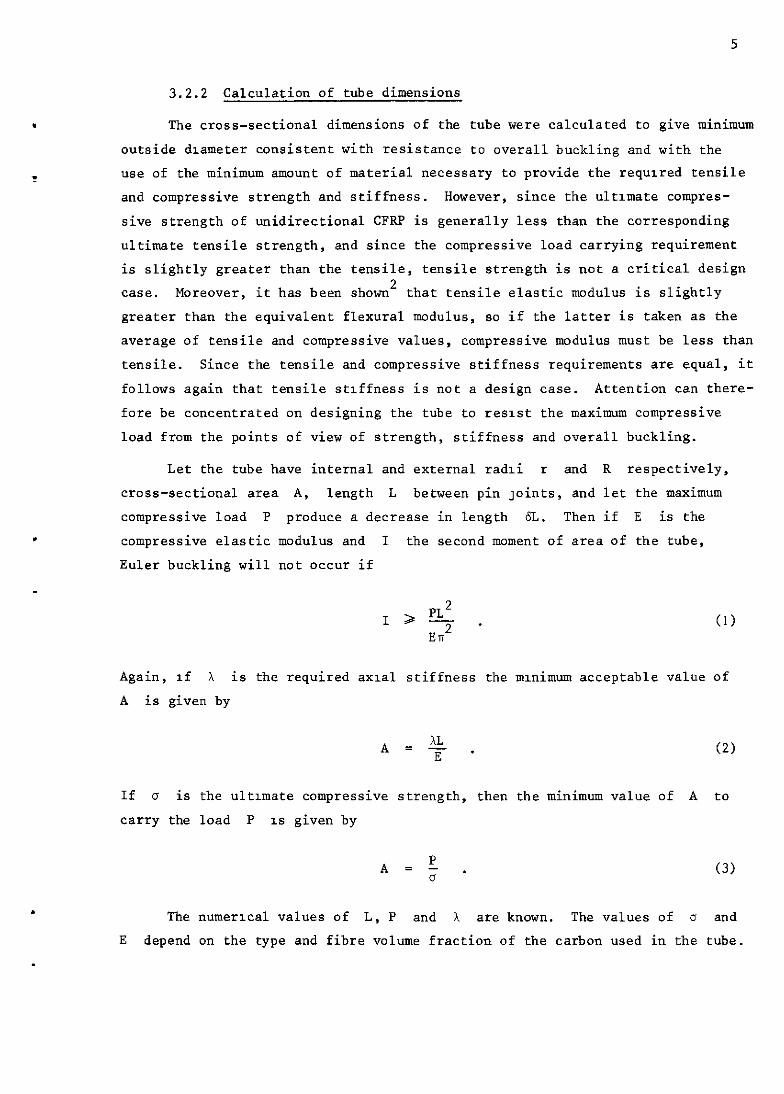
3.2.2 Calculation of tube dimensions
The cross-sectional dimensions of the
outside diameter consistent with resistance
tube were calculated to give minimum
to overall buckling and with the
use of the minimum amount of material necessary to provide the required tensile
and compressive strength and stiffness. However, since the ultmate compres-
sive strength of unidirectional CFRP is generally less than the corresponding
ultimate tensile strength, and since the compressive load carrying requirement
is slightly greater than the tensile, tensile strength is not a critical design
case. Moreover, it has been shown2 that tensile elastic modulus is slightly
greater than the equivalent flexural modulus, so if the latter is taken as the
average of tensile and compressive values, compressive modulus must be less than
tensile. Since the tensile and compressive stiffness requirements are equal, it
follows again that tensile stiffness is not a design case. Attention can there-
fore be concentrated on designing the tube to resist the maximum compressive
load from the points of view of strength, stiffness and overall buckling.
Let the tube have internal and external radii r and R respectively,
cross-sectional area A, length L between pin joints, and let the maximum
compressive load P produce a decrease in length 6L. Then if E is the
compressive elastic modulus and I the second moment of area of the tube,
Euler buckling will not occur if
I 2 pL 2
- . El12
Again, If X is the required axial stiffness the mmimum acceptable value of
A is given by
If 0 is the ultmate compressive strength, then the minimum value of A to
carry the load P IS given by
A=:. (3)
The numerical values of L, P and X are known. The values of 0 and
E depend on the type and fibre volume fraction of the carbon used in the tube.

6
Because preliminary calculations showed that compressive stiffness rather than
strength was likely to be the dominant consideration, Type I fibre was chosen
at a fibre volume fraction vf of 0.50, which was about the highest which
could be moulded easily. A typical fibre tensile elastic modulus for this
material is 414 GN/m2; using this figure and the results of Ref.2, and assum-
ing flexural composite modulus to be the average of the tensile and compres-
sive figures, E was calculated to be 163 GN/m2 and this figure was used in
the tube design. For the same composite material 448 MN/m2 is a typical value
for 0 and this also was used for design.
Minimum values of I and A were then calculated from equations (1) to
(3) and found to be,
I = 34590 nun4
A = 290.3 mm2 .
It 1s evident from these calculations that the critical design constraints are
governed by equations (I) and (2); that is the second moment of area required
to prevent buckling and the area required to give adequate linear compressive
stiffness. Now since I = z (R4 - r4) and A = n(R2 - r2), we have
Substitution of the values of I and A from equations (I) and (2) respec-
tlvely gives the minimum internal tube radius
?z = 13.87 mm
and hence the mlnimum external tube radius
R = 16.84 nrm .
These dimensions were rounded up to the nearest practical Imperial sizes,
giving the following values which were used in the experimental work:
r = 14.29 mm
R = 17.46 mm .
7
.
.
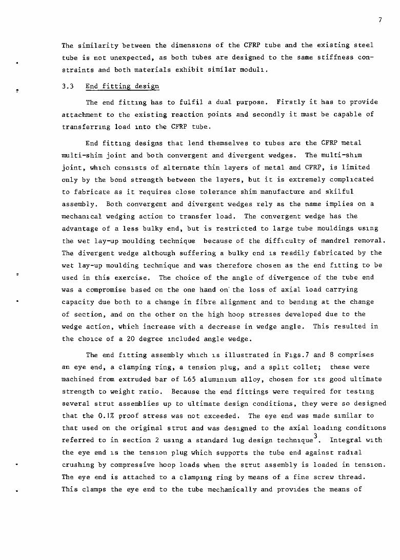
The similarity between the dimensmns of the CFRP tube and the existing steel
tube is not unexpected, as both tubes are designed to the same stiffness con-
straints and both materials exhibit similar modull.
3.3 End fitting design
The end fittmg has to fulfil a dual purpose. Firstly it has to provide
attachment to the existing reaction points and secondly it must be capable of
transferrmg load Into the CFRP tube.
End fitting designs that lend themselves to tubes are the CFRP metal
multi-shim joint and both convergent and divergent wedges. The multi-shun
joint, which consists of alternate thin layers of metal and CFRP, is limited
only by the bond strength between the layers, but it is extremely complicated
to fabricate as it requires close tolerance shim manufacture and skilful
~SWUbly. Both convergent and divergent wedges rely as the name implies on a
mechanIca wedging action to transfer load. The convergent wedge has the
advantage of a less bulky end, but is restricted to large tube mouldings usug
the wet lay-up moulding technique because of the difficulty of mandrel removal.
The divergent wedge although suffering a bulky end 1s readily fabricated by the
wet lay-up moulding technique and was therefore chosen as the end fitting to be
used in this exercise. The choice of the angle of divergence of the tube end
was a compromise based on the one hand on'the loss of axial load carrying
capacity due both to a change in fibre alignment and to bendrng at the change
of section, and on the other on the high hoop stresses developed due to the
wedge action, which increase with a decrease in wedge angle. This resulted in
the choice of a 20 degree Included angle wedge.
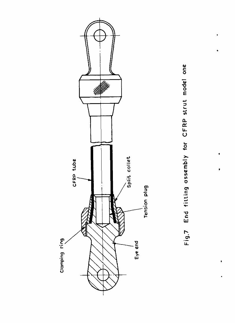
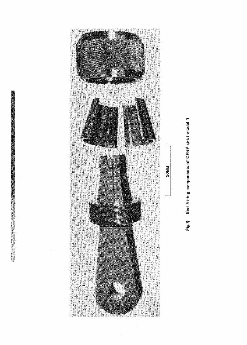
The end fitting assembly which 1s illustrated in Flgs.7 and 8 comprises
an eye end, a clamping ring, a tension plug, and a split collet; these were
machined from extruded bar of L65 alununxxn alloy, chosen for Its good ultimate
strength to weight ratio. Because the end fittings were required for testing
several strut assemblies up to ultimate design conditions, they were so designed
that the 0.1% proof stress was not exceeded. The eye end was made similar to
that used on the original strut and was deslgned to the axial loading conditions
referred to in section 2 usxng a standard lug design technique 3 . Integral with
the eye end 1s the tenslon plug which supports the tube end against radial
crushing by compressive hoop loads when the strut assembly is loaded in tensIon.
The eye end is attached to a clamping ring by means of a fine screw thread.
This clamps the eye end to the tube mechanically and provides the means of

transferring the tensile axial load from one to the other. Note that the clamping ring is subjected to both axial and hoop tensile loads. To facilicdte the clamping of the tube end by the clamping ring, a split collet is provided. Compression loads are taken on the end face of the tube through dlrec~ contact with the eye end. The tension plug, split collet and clamping ring provide end support to the CFRP. Figs.9 and IO show the action of the end fitting under both loading conditions.
The axial stiffness XT of the strut assembly can be calculated from the follo~wing equation
I 'T = i=* )
If i=l i
(4)
where n is the number of components contributing to the stiffness of the strut assembly and Xi is the stiffness of the ith component. In the tensile case the components contributing to the overall stiffness are the CFRP tube, the clamping rings and the eye ends. In compression the components are the CFRP tube and the eye ends. The stiffnesses of the components can be calculated from equation (2) and are as follows;
CFRP tube 163 kN/mm Eye end 580 kN/mm Clamping ring 2170 IrN/mm .
The tensile and compressive stiffnesses of the strut assembly can be calculated using equation (4), and are 104 kN/mm and 95.3 kN/mn respectively.
4 CFRP STRUT MODEL ONE
4.1 Strut fabrication
The main CFRP member was fabricated by a wet lay-up process in which the flow of excess resin out of the moulds ends assists in aligning the fibres. The mould is shown in Figs.11 and 12. Half the weighed amount of type I carbon fibre (cut from metre length untreated Morganite material) together with excess resin* was layered in the lower half of the mould with the fibres parallel to the tube axis. After coating with resin the mandrel was aligned in the mould
* SHELL 828 resin, MNA and benzyl dimethylamine Q 100/85/l parts by weight.
.
9
.
.
.
and the remaining half of the fibre and resin layered over the mandrel. The
upper half of the mould was then posltloned and the whole assembly placed in a
hot press at IOO'C and allowed to soak at this temperature until the viscosity
of the resin was such that it readily flowed from the ends of the mould. Using
a pressure of approximately 345 N/m*, the mould was closed allowing all excess
resin to flow out of the mould ends. The mould was then pressed to stops and
the component cured in situ for one hour at IOO'C, followed by a post cure of
24 hours at 12O'C in an air circulating oven.
This fabrication process produced a tube wl'ch divergent ends which when
trimmed conformed to the dimensions shown in Fig.6.
The fibre volume fraction was determined from the weight and density of
fibre used and the volume of the tube. A figure of 0.50 was aimed at, but
subsequent accurate fibre density measurements showed the value to be 0.48 and
all subsequent tubes were made to this figure unless otherwise stated.
The weights of the CFRP strut and the aluminium alloy end components were;
CFRP tube 260 g
Two split collets 82 g
Two eye ends and two tension plugs 824 g
Two clamping rings 410 g
Total 4.2 Tensile test
1576 g
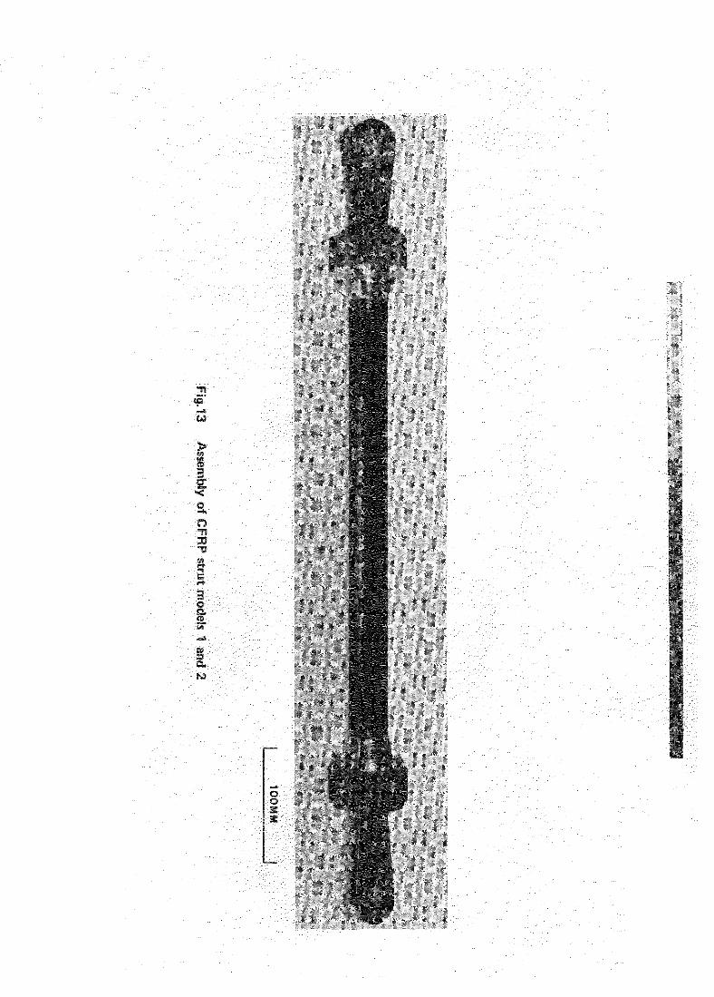
The assembled strut shown m Fig.13 was tested in tensIon between pin
Joints III an Avery testing machine. Failure occurred in the end fitting
through circumferential crushing of the CFRP tube end by the compressive hoop
stresses produced by the end fittings. This caused a shrinkage m the tube
end sectlon, and subsequent extrusion of the tube from between the split collet
and tensIon plug. The falling load was 26.6 kN.
5 CFRP STRUT MODEL TWO
5.1 Modification of strut design
Two significant changes were made in the design and fabrication of this
model. Firstly the fibre was surface treated by oxidation 4 in air at 55O'C
to a weight loss of at least 0.67% (the fibre used in this strut was made up
from batches of fibre whose oxidised weight loss ranged between 0.67% and 1.2%).
Secondly the end fittings were modified by separating the tension plug from the
eye end and securing It to the CFRP tube with adhesive (3M's EC2216). This
IO
allowed the tensmn plug to move axially with the CFRP tube, preventmg radial
collapse and extrusion of the tube end. Surface preparatmn of the tension
plug prur to glueing consisted of mechanical cleanmg using a fine emery
paper, followed by a surface preparation process using chromium trioxide to
Specification DTD 915B. The CFRP tube surface was prepared by mechanical
cleaning using a fine emery paper followed by washing in distilled water and
finally drying in an air circulating oven.
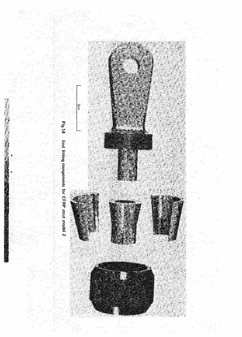
To ald alignment of the tube and end fittings a central spigot was
added to the eye end, Figs.14 and 15 show the modified end fittings and their
assembly.
5.2 Tensile tests
The strut assembly designated 2/I, with split collets assembled dry,
was tested in tension as before and failed at 37.9 kN. Failure occurred at
the change of section at the tube end. Subsequent examination of this
failure showed that the split collets were not fitting correctly around the
tube at the change of section and were consequently causing a stress concen-
tration and surface fibre damage. To overcome this, subsequent struts were
assembled with split collets that had been given a generous radius at the
change of section, and to allow for fitting errors they were secured with
adhesive. The adhesive and surface preparations used were the same as for
the tension plug referred to ln sectIon 5.1. Three further struts designated
Z/II, Z/III and Z/IV were assembled using the modified split collet and then
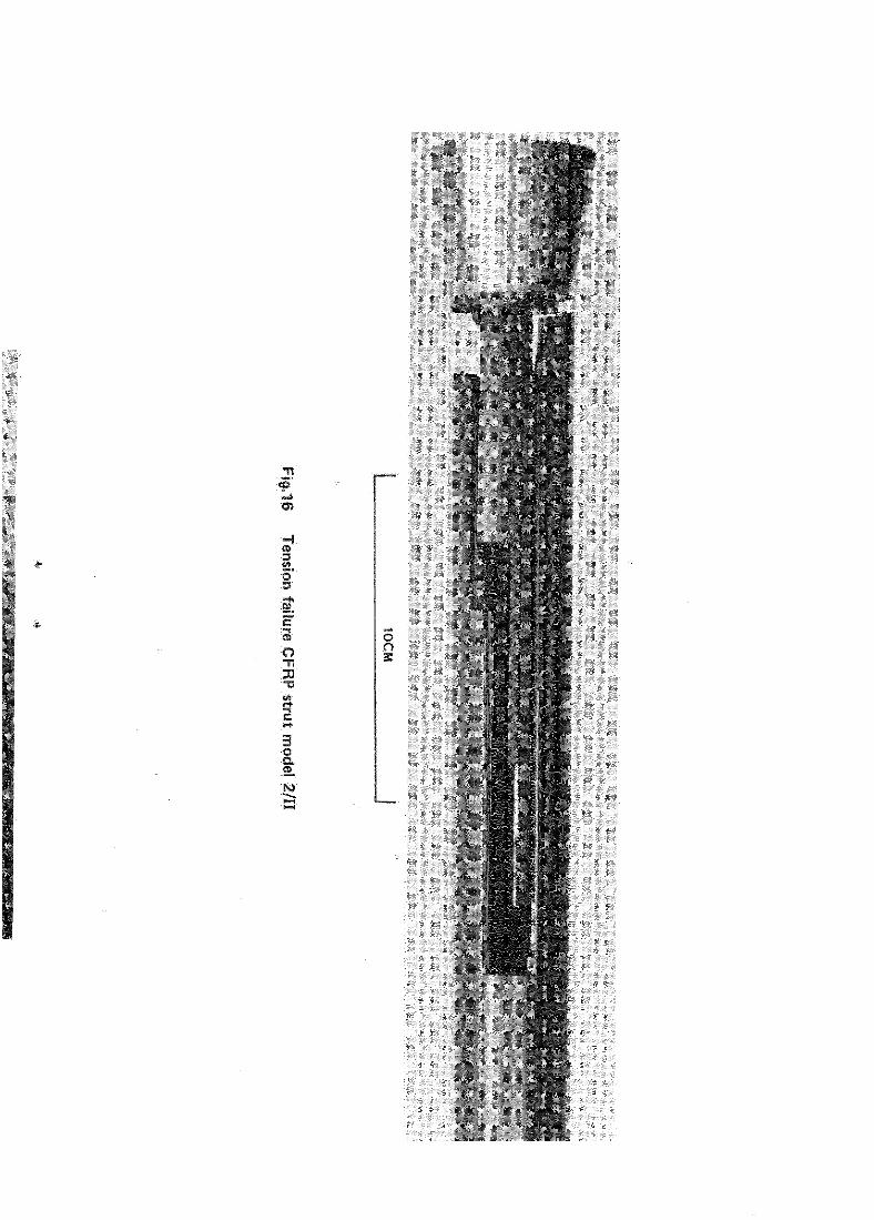
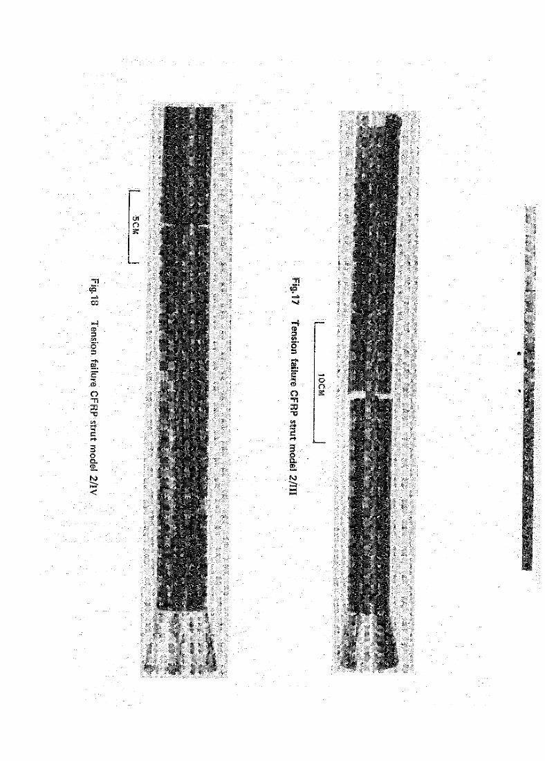
tested in tensIon as before. Failure of strut Z/II, shown in Fig.16, began
at the end fitting at a load of 94.7 kN. Struts Z/III and Z/IV both failed
in tension remote from the ends at 85.7 kN and 67.8 kN respectively. Flgs.17
and 18 show the failed tubes.
Because the failures of the last two struts were apparently uninfluenced
by the ends, the fibre stress at fallure should have approached the fibre
ultimate tensile strength (1434 MN/m2). It was in fact substantially lower m
both cases (568 MN/m2 and 450 MN/m2 respectively). This led to a separate
investigation, reported elsewhere5, whrch showed that the fibre surface treat-
ment described in section 5.1 had substantially reduced the fibre ultimate
tensile strength. The treatment was therefore changed from model 3 onwards
and this 1s detalled in section 6.1.
11
5.3 Compression tests
.
.
In order to provide direct Information on the ultimate compressive
strength of the CFRP tubes for comparxson with the design figure, several
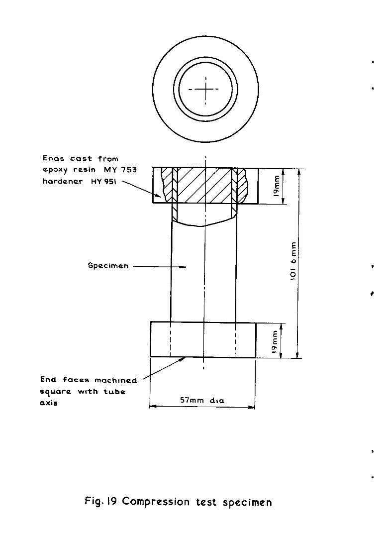
specimens were cut from a moulded CFRP tube and tested. They consisted of
tube sections 102 mm long whose ends were cast in an epoxy resin* to give
lateral support to the fibre ends. To ensure true axial loading of the speci-
mens the cast end faces were machined square with the tube axis and the tests
were carried out between the parallel compression platens of an Avery testing
machine. One specimen with an end fitting assembled was also tested in com-
pression to determine the effect, if any, on the compression strength of the
CFRP tube.
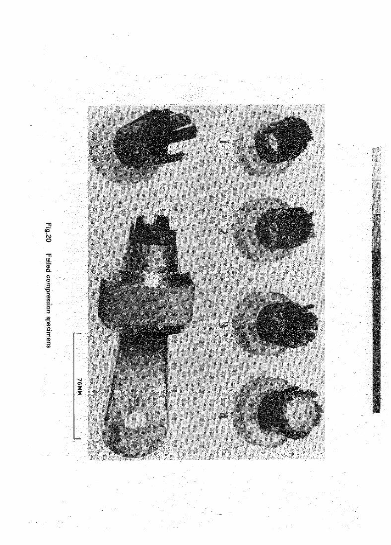
The results and modes of failure are listed in Table I. Figs.19 and 7.0
show the compression specimen and failed specimens respectively. The four
tube section specimens gave a mean composite compression strength of
458 wm2 which compares closely with the figure of 448 MN/m2 used for design
(see sectlon 3.2.2). The tube cross-sectional area was, however, larger than
the minimum design value in order to use practical Imperial sizes, and for the
actual tube the maximum compressive design load corresponds to a stress of
only 390 MN/m2. The composite falling stress of the end fitting assembly of
390 MN/m2 shows that this end flttlng is just adequate for these design
conditions.
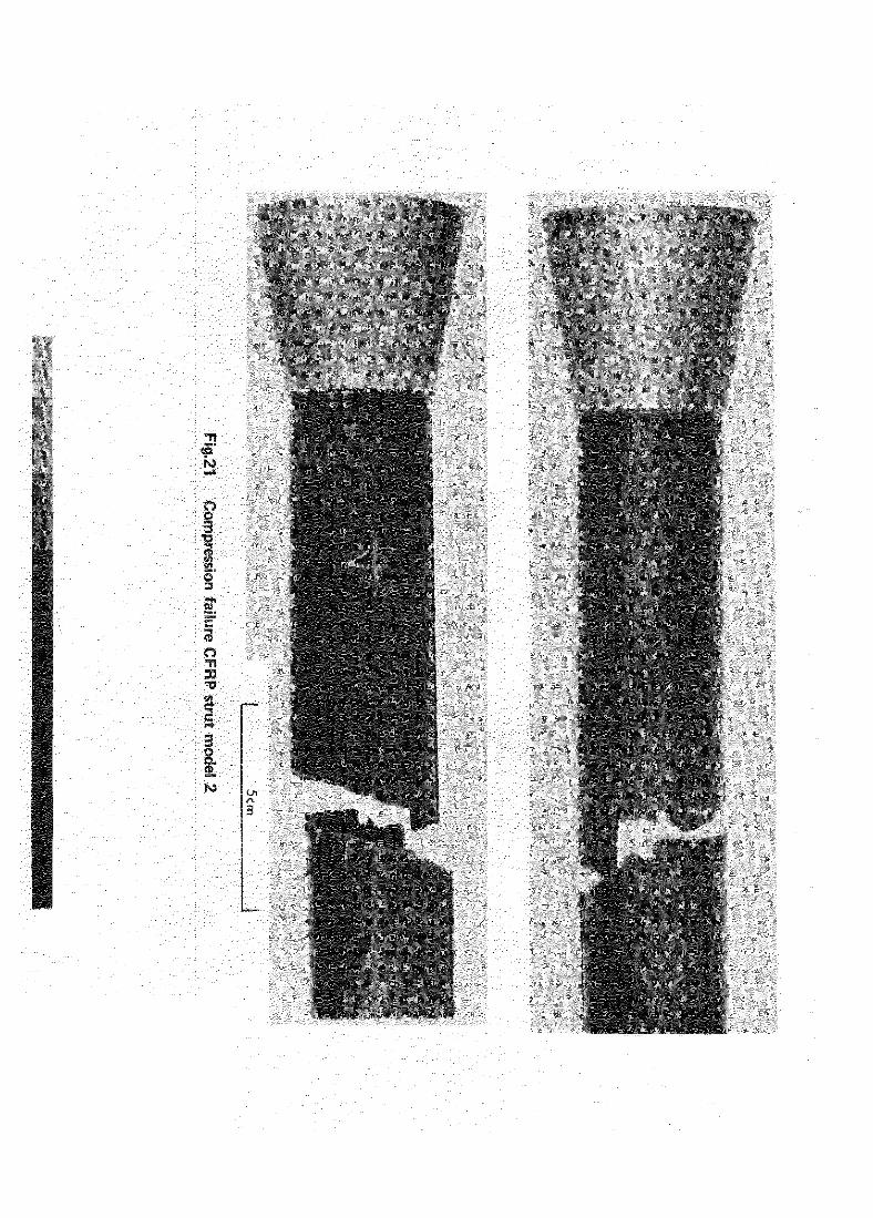
A complete strut assembly with both tension plug and split collet secured
with adhesive was tested in compressvan between pin joints in an Avery testing
machine. Failure occurred in about 30 s at a load of 108 kN approximately one
third of the way along the langth of the CFRP tube. Fig.21 shows the falled
specimen. The compression strength of 344 MN/m2 obtained from this test is
rather lower than the figure of 390 MN/m 2 for a single end and may have been
influenced by some misalignment of the end fittings.
6 CFRP STRUT MODEL THREE
6.1 Modiflcatlon of strut design
Several changes were made to the design as the result of experience.
Fibre surface treatment was changed to a wet oxldatlon process using
sodium hypochlorite5. This gave improved composite shear strength without
* CIBA MY753 resin and HY951 hardener % 6/i parts by volume cured at room temperature.
12
degrading the fibre tensile strength. The fibre used for this strut and
subsequent struts was a Morganite fibre whose tensile strength was 2040 MN/m2.
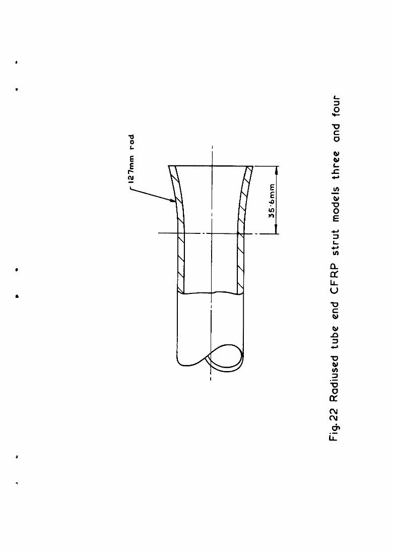
Failures were still occurring at the ends SO, to reduce stress concen-
tration effects due to the abrupt change of section near the end of the CFW tube, the shape was modified as shown in Fig.22.
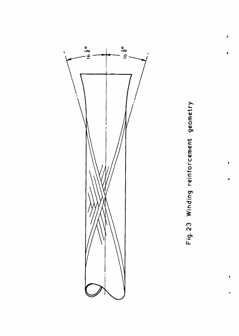
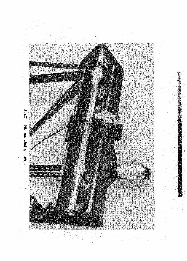
To give some arbitrary transverse and torsional strength and better
handling characteristics to the CFRP tube, a thin inner core tube was provided;
this was helically wound onto a steel mandrel in surface treated type II fibre two tows thick to the pattern shown in Fig.23 using the filament winding machine 6 shown in Fig.24. Fabrication was then continued as described in
section 4.1 giving unidirectional CFRP over the core tube. The overall fibre
volume fraction in the tube section was 0.504.
Modification to the end fittings consisted of changing the design con-
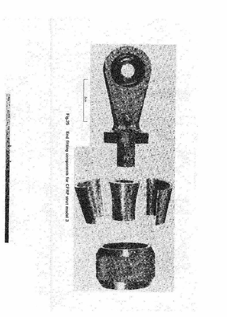
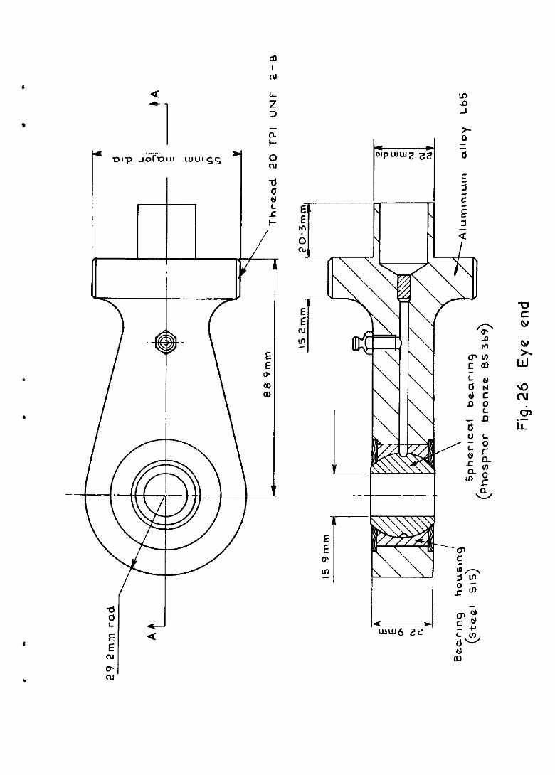
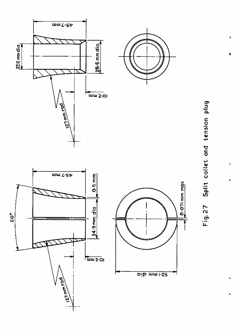
ditions from proof to ultimate figures and the inclusion of a spherical bearing similar to that used on the original strut. This bearing gives a full three degrees of freedom against unwanted induced bending and twisting loads. The split collet and tension plug ware modified to suit the new shape of the tube ends. Figs.25 to 27 show respectively the modified end fittings, details of the eye end, and the split collet and tension plug.
Redesign of the eye end reduced the amount of aluminium alloy used, but spherical bearings added additional weight. Each redesigned eye end weighed 450 g giving a strut assembly weight of 1740 g.
6.2 Tensile tests
A strut assembly incorporating the new modifications was tested in
tension and failed in the end fitting at a level of 113 kN due to a bearing failure m the split collet and clamping ring. Subsequent examination indicated that there was a lack of fit between the tapers of the split collet and the clamping ring so that only a fraction of the theoretical load bearing area was in contact. This lack of fit caused distortions in both components and was remedied by machining subsequent split collets after assembly, giving concentricity with the tube's axis and positive mating with the clamping ring.
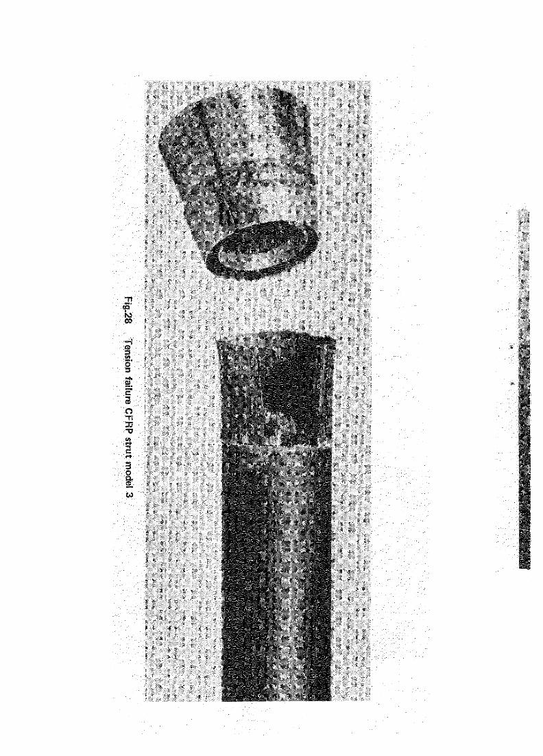
A second strut, modified in this way, was assembled and tested, giving a failing load of 116.6 kN. Failure in this case was initiated by transverse compresslve7 failure of the CFRP inslde the end fitting approximately I5 mm from the end of the tube, propagating around 85% of the tube's circumference.
13
.
.
This was followed by longitudinal shearing of the CFRP parallel to the tube
axis as far as the change of tube section, where the remaining 15X failed in
tension. Fig.28 shows the failed specimen.
An approximate stress analysis of the tube end has shown that compres-
slve hoop stresses of about 480 MN/m2 would occur at this latest tensile
failing load. This agrees quite well with transverse compression strength
tests 7 carried out on specimens made from the same fibre and resin system, and
subjected to similar constraint, which gave ultimate failing strengths of
517 MN/m* and 603 MN/m* corresponding to fibre volume fractions of 0.4 and
0.5 respectively.
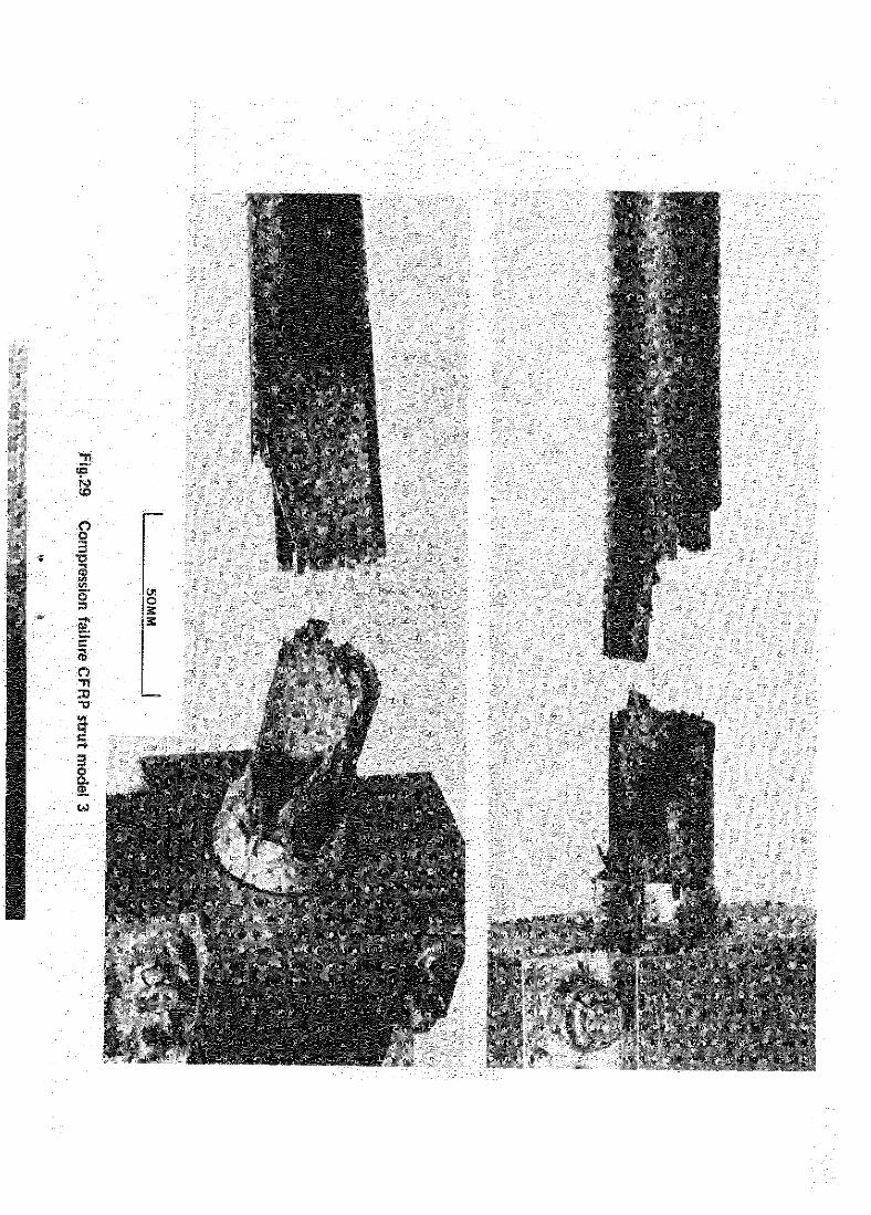
6.3 Compression test
A strut assembly with all modifwations was loaded in compressIon and
failure occurred at the end fitting at a load of 117 kN, giving a composite
compressive stress at failure of 372 MN/m*. This was not significantly better
than strut two and still below the design stress of 390 MN/m*. From the
appearance of the strut, shown m Fig.29, faxlure may have been caused by a
lack of pre-tightening of the clamping ring, so that under a compressive load
some axial settlement m the tube end left the tube end unsupported except
for the split collet.
7 CFRP STRUT MODEL FOUR
7.1 Modification of strut design
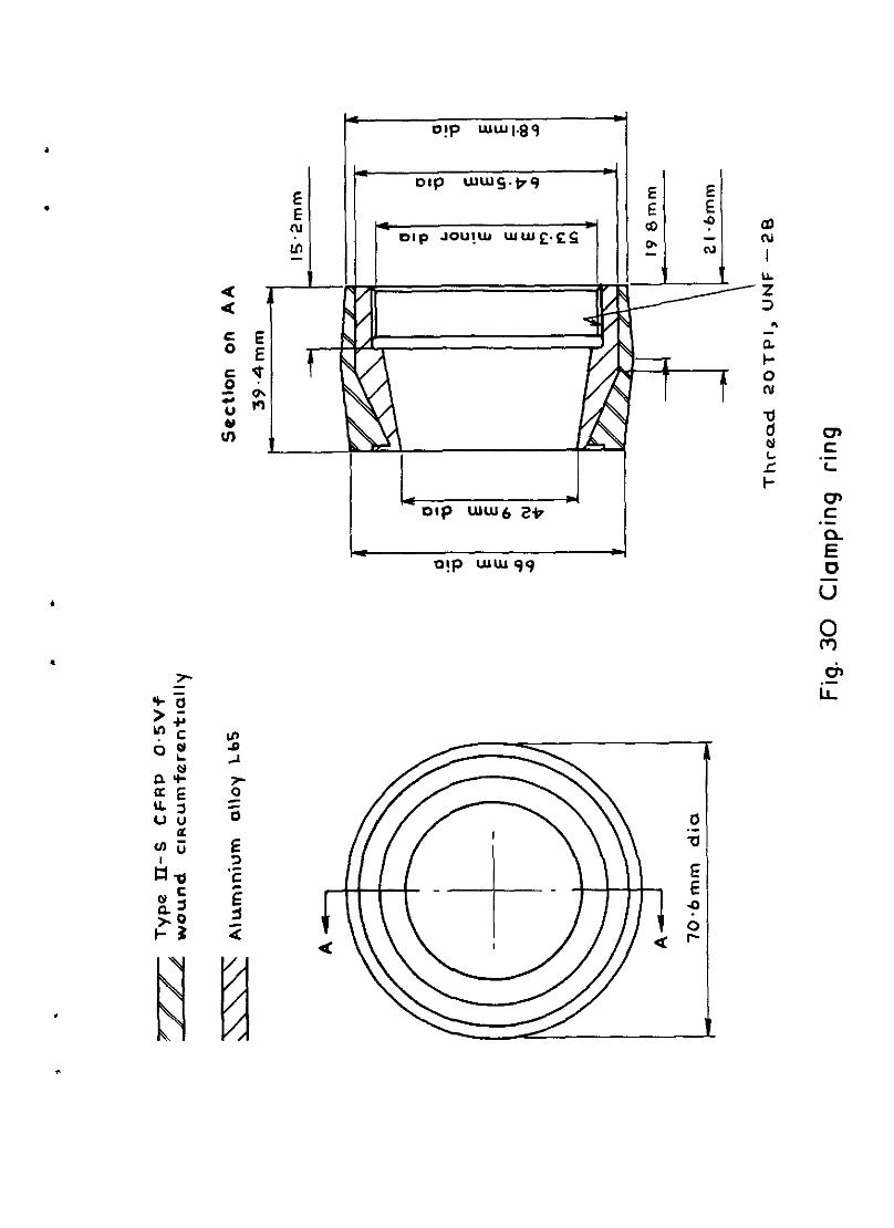
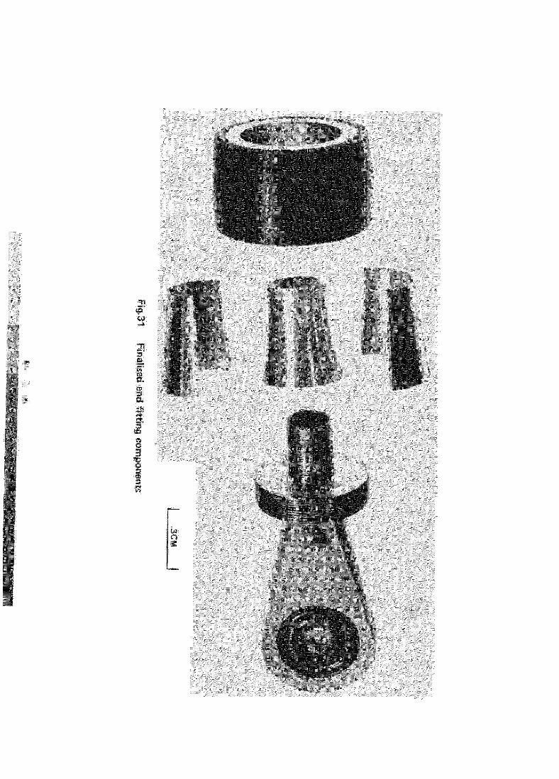
To finalise the design of the end attachment the clamping ring was
redeslgned ln an aluminium alloy CFRP material combination. This consisted of
an aluminium alloy L65 screwed ring designed to take the tensile axial loads,
over which a continuous type II carbon fibre with epoxy resin* was clrcum-
ferentially wound. This overwind (v, = 0.50) was finally machined to an
appropriate diameter and shape to take the tensile hoop stresses m an
efficient manner. The maximum hoop stresses developed in the clamping ring were
calculated to be 472 MN/m* at the tube end and 692 MN/m* at a point 19 mm from
the tube end. This modification resulted in a weight saving on each clamping
ring of 50 g, giving a 25 par cent weight reduction on the orlginal clamping
ring. Flg.30 illustrates in detail the new clamping ring and Flg.31 the
finalised end fitting components.
* Shell 828 resin, MNA and benzyl dxnethylamine 1. 100/85/l parts by weight, cured at 100°C for I hour, post cured at 120% for 24 hours.
14
Fabrication of the CFRP tube was carried out as referred to in section 6.1 using the same type I and type II carbon fibre but with an increase in volume fraction of the type I carbon from 0.48 to 0.5, making the total volume fraction of carbon in the tube 0.524.
The weight of the final CFRP strut components were:
CFRP tube 260 g Two split collets 82 g Two eye ends 900 g Two tension plugs 87 g Two clamping rings 308 g
Total 1637 g
7.2 Tensile tests
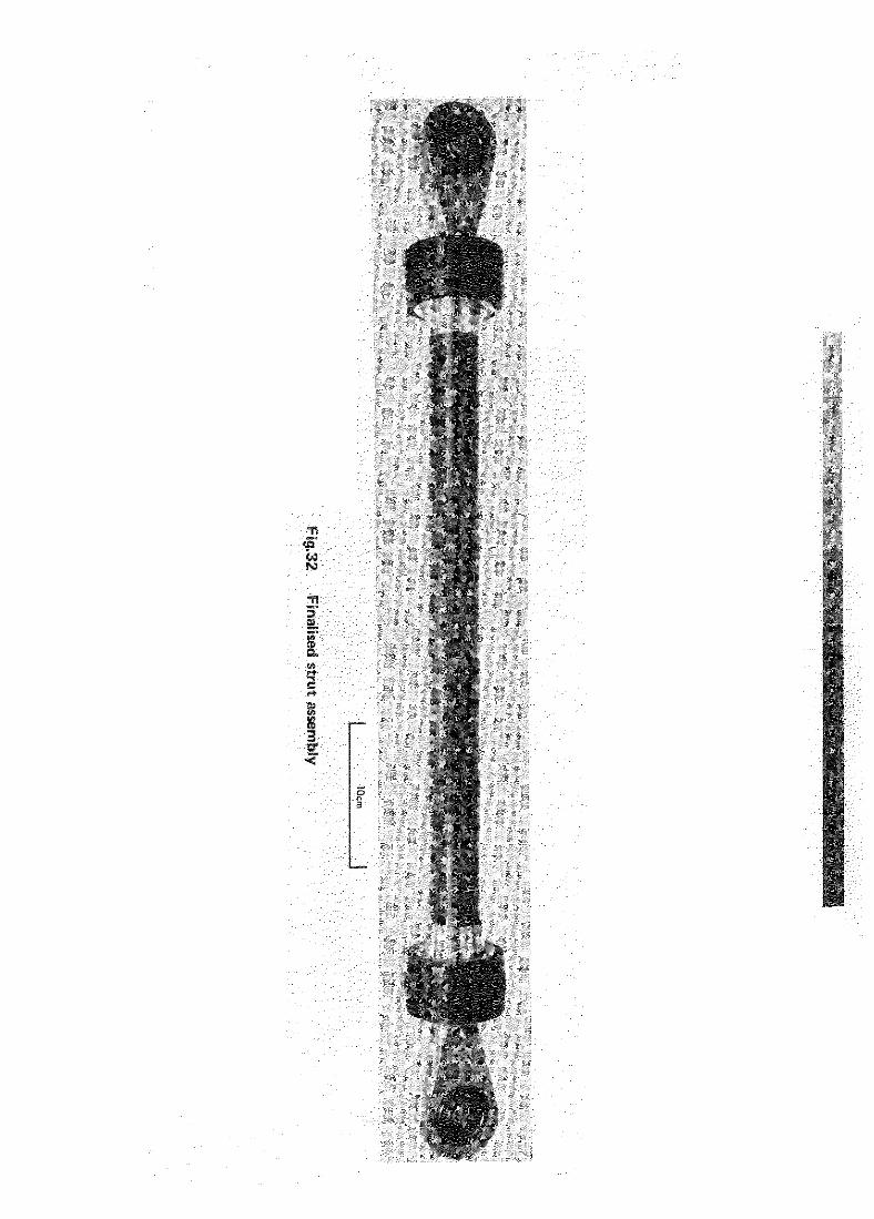
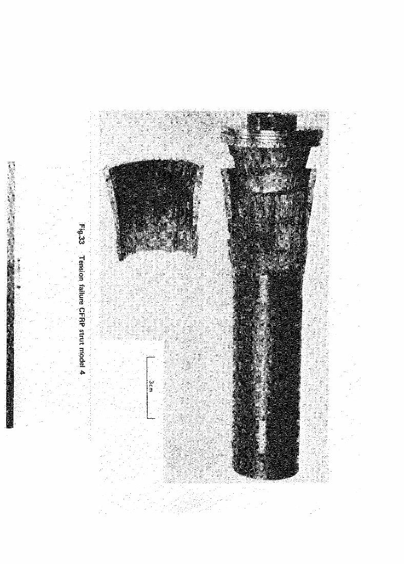
7.2.1 Strength test
A strut assembly made to the final design, shown in Fig.32, was tested
in tension and failed in the end fittmg at a load of 117.6 kN at which the fibre stress was 770 MN/m2. As before, failure was caused by a transverse compression failure of the CFRP inside the end fitting, this time approxl- mately 8 mn from the end of the tube, followed by longitudinal shearing of the CFRP. Flg.33 shows the failed specimen. The tensile strength so measured satisfied the axial tensile loading requirement, but tensile tests5 of CFRP specimens made from the same material as the tube have shown that a
fibre strength of 1836 MN/m2 can be achieved, so that the efficiency of the
end m tension is only about 41%. The limit is set by the transverse com-
pressive strength of the CFE'. The transverse compressive stresses may be reduced somewhat by changing the rate of divergence of the tube end, but there does not appear to be much scope for unprovlng tensile efficiency with this type of end design.
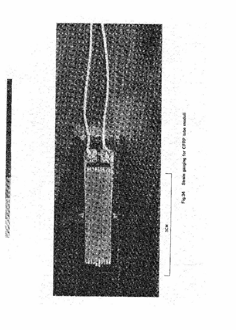
7.2.2 Tube modulus measurement
The tensile elastic modulus of the CFRP tube was measured by a Strain gauge technique. A foil strain gauge* was secured with adhesive** to the
* Saunders Roe batch 1843, 25.4 mm long, 100 ohm resistance and gauge factor 2.12.
** CIBA MY753 resin and HY951 hardener * 6/l parts by volume, cured at room temperature.
15
.
.
outside wall of the CFRP tube of a strut assembly, and aligned parallel with
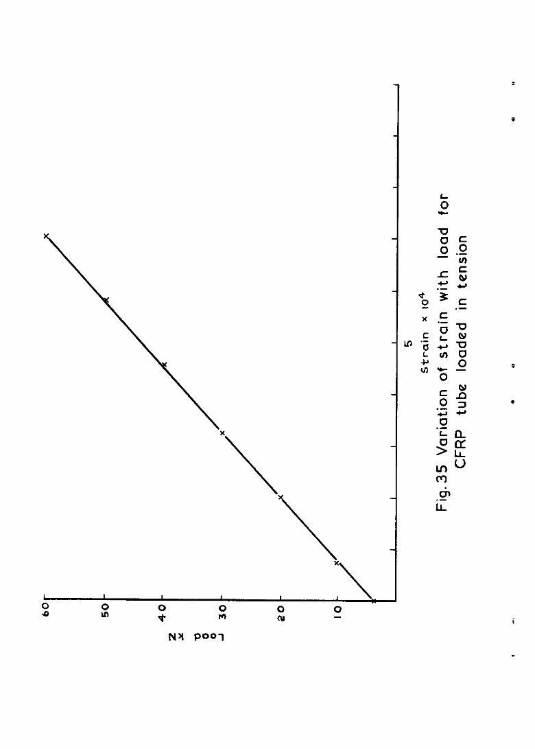
the tube axis as shown in Flg.34. A dlgital voltmeter was used for measuring
the bridge voltage and also the output of the strain gauge, using a conven-
tional Wheatstone bridge network. The strut assembly was loaded in tension
between pin joints in an Avery test machine in load increments of IO kN from
10 kN to 60 kN, the corresponding strain being recorded at each load. Fig.35
shows the load/strain curve plotted from the test results. The tensile elastic
modulus calculated from these results was 255 GN/m' , which was in good agree-
ment with the flgure of 234 GN/m' derived from the fibre modulus and the law of
mixtures.
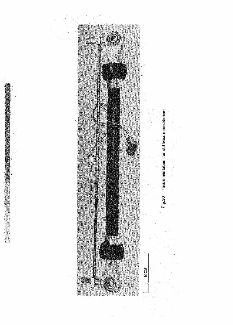
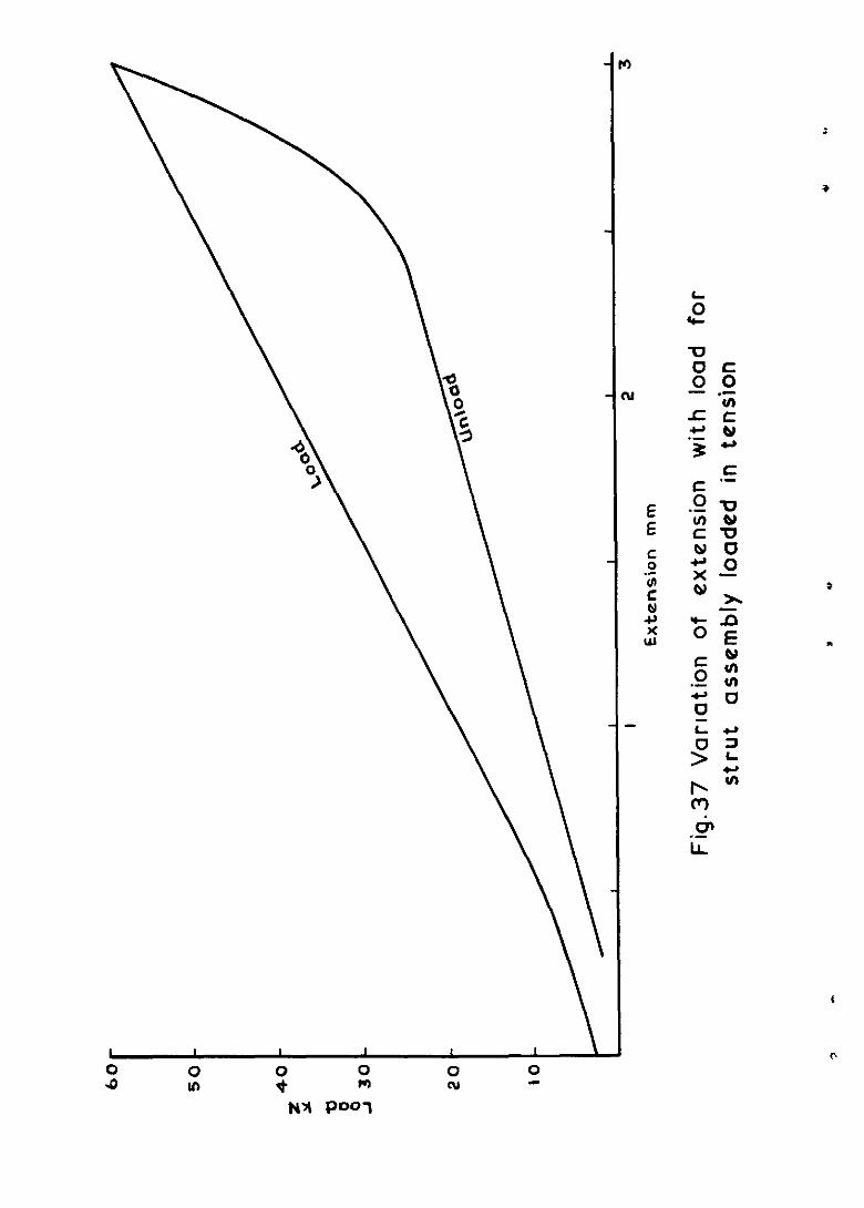
7.2.3 Stiffness measurement
The tensile stiffness of the strut assembly is the load requiredtoincrease
the length between loading pins by one unit of length. Direct measurement of
this extension between the loading pins 1s not practical however because of pin
deflectlons suffered under load. Measurements were therefore taken between the
side pins, shown in Fig.36 which were secured to each eye fitting normal to the
strut and pin axes, and ln line with the pin jornt centres.
To measure the tensile stiffness the strut assembly used in section 7.2.2
was loaded in tension between pin Joints, the load being applied in Increments
of 2.5 kN up to a maxxmnn of 60 kNN. At each load increment the corresponding
x~rease in length was measured using a telescopic tube and displacement trans-
ducer (linearly variable differential transformer) mounted between the side pins,
the voltage output of the transducer being measured with a digltal voltmeter.
Fig.37 shows the load extension curve for the loading and unloading cycle. The
slope of the linear portion of the curve on the loading cycle gives the stiff-
nes.s of the strut assembly as 20.4 kN/mm.
Although the value obtained during a single loading cycle must be treated
with caution, the result obtalned falls so far below specification as not to
merit an investigation lnvolvlng repeated loading which would at that tune have
been lnconvenlent. It IS, however, of Interest to compare this value with a
single theoretIca estimate calculated in the manner described in section 3.3.
Because of the modifications to the strut components the tensile stiffness
of each finalised component was re-estimated using equation (2) giving the
following values:
16
CFRP tube 163 kN/mm
Eye end 490 kN/mm
Clamplng ring 1420 kN/mm
The tensile stiffness of the finalised strut assembly determlned from
equation (4) is then 86 kN/mm.
The measured tensile stiffness 1s very much lower than that calculated,
and this is clearly due to the method of end attachment. The qualitative
explanation is as follows. It has already been shown that axial tensile
loads generate substantial radial stresses in the dlvergent wedge end of the
CFRP tube; Indeed, these same stresses eventually initiate overall tensile
failure. Because the transverse compressive modulus of the tube is low
(about 7 GN/m2), these stresses lead to substantial radial elastic deforma-
tions. These in turn lead to axial movement in the wedge, the magnitude of
which 1s aggravated by the relatively shallow wedge angle. It is these
strains which explain the difference between the measured and calculated
overall stiffness.
The marked hysterisis effect evident in Fig.37 arises largely ln the
end fitting, in particular from the friction between the tube end and the
clamping ring during unloading.
7.3 Compression tests
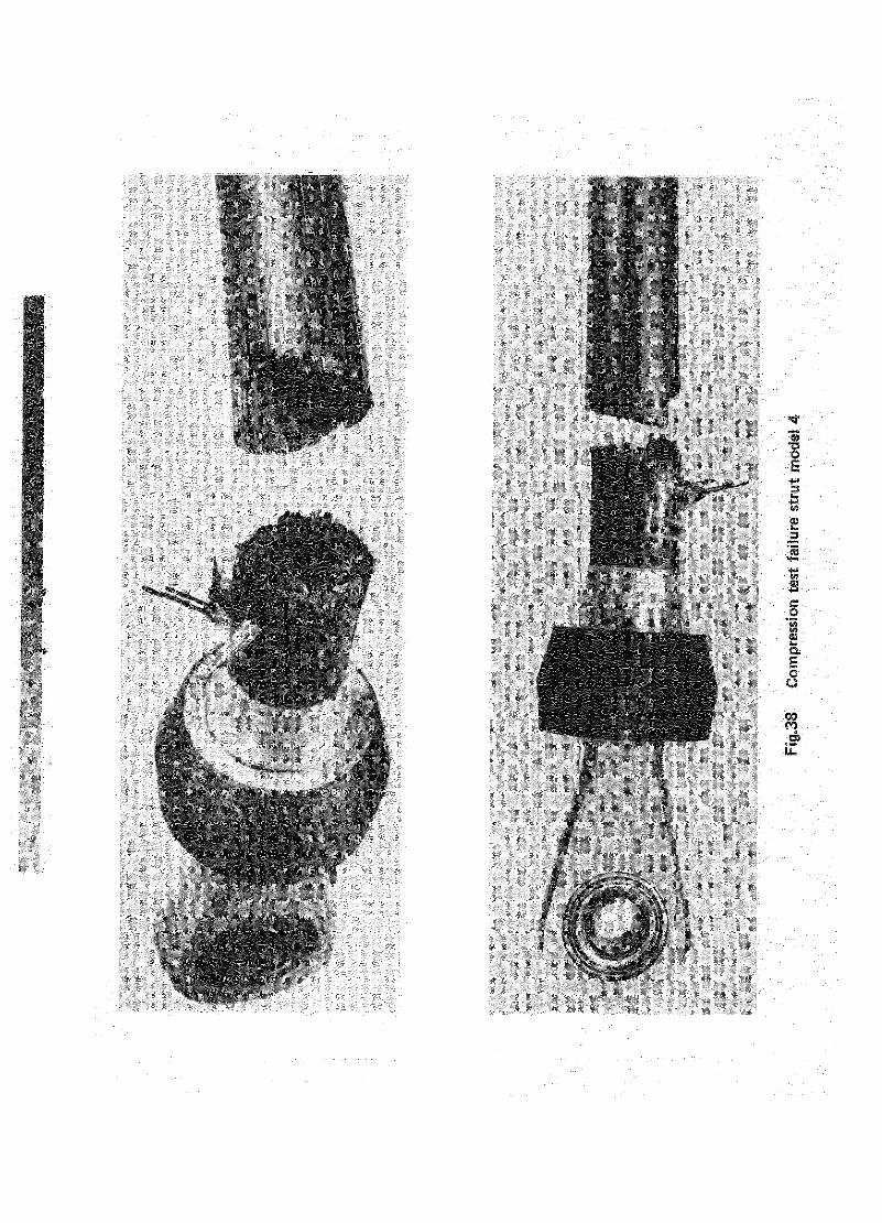
7.3.1 Strength test
A strut assembly made to the flnal design (Flg.32) was tested in com-
pPZSSlO*. Failure occurred in about 30 s away from the end fitting at a
load of 141.5 ICN, corresponding to a composite compressive stress of
450 m/m2. This mc~re than satisfied the compressive load requlrement of
122.8 kN. Fig.38 shows the failed specimen.
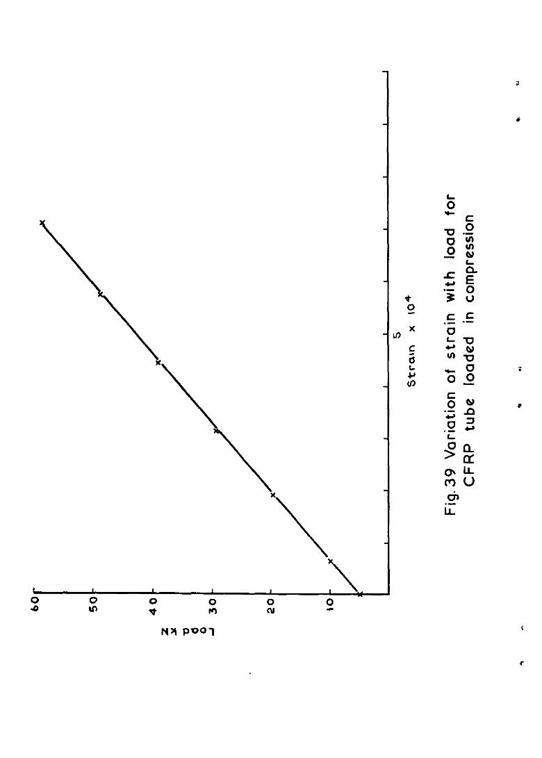
7.3.2 Tube modulus measurement
The compressive modulus of the CFRP tube was measured usxng the same
method and strut assembly as used for the tensile modulus described in
section 7.2.2. Fig.39 shows the load/strain curve plotted from the test
results. The compressive elastic modulus calculated from these results was
247 GN/m2, while the modulus estimated ln section 3.2.2 using the results of
Ref.2 was only 163 GN/m2. The tensile modulus of the fibre used was 10%
higher than the figure used in the design calculations, but nevertheless the
17
assumptions used in section 3.2.2 were evidently unduly conservative as the
compressive modulus measured here is little different from the tensile figure.
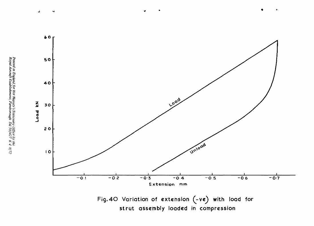
7.3.3 Stiffness measurement
The overall compressive stiffness was measured using the method described
in sectlon 7.2.3 for the measurement of tensile stiffness. Fig.40 shows the
load extension (-ve) curve for the loading and unloading cycle. The slope of
the linear portIon of the curve on the loading cycle gives the stiffness of the
strut assembly as 88.5 kN/rmn. The theoretIca stiffness calculated from
equation (4) in section 3.3, and using the re-calculated stiffness for the
strut components referred to in section 7.2.3, was 98 kN/mm. This agrees
adequately with the measured value.
The measured value satisfies the design tensile stiffness value of
70 kN/mm (section 2). The close agreement between measured and calculated
values in this case highlights the difference in stress distribution between
the tensile and compressive cases. In the former load 1s transferred from the
pin via the clamping ring and this generates high transverse compressive
stresses with the results which have been described in section 7.2.3. In the
latter load is transferred dn-ectly from the eye end to the ends of the tension
plug, tube and split collet.
Under axial compression the strut suffers an axial strain which for
increasing load is linearly proportional to the applied load (Fig.40). During
unloading however the strain is far from linear and the strut exhibits a
marked hysteresis. A possible explanation 1s that during loading the flared
end of the CFRP tube 1s subjected to stresses which cause a change ln the
local tube diameter. This in turn causes a significant amount of relative
movement between the clamplng rxng and the tapered split collet. During the
unloading cycle relative movement between the two components is InhibIted by
friction forces and such movement does not occur until the frictxnxal forces
are overcome, resulting in apparent hysteresis.
It can be seen that the deformation of the tube end has a less effect on
overall hysterlsu in compression than ln tensIon. As previously described
(section 7.2.3), hysteresis in tensIon 1s largely caused by the wedge action.
8 DISCUSSION AND CONCLUSIONS
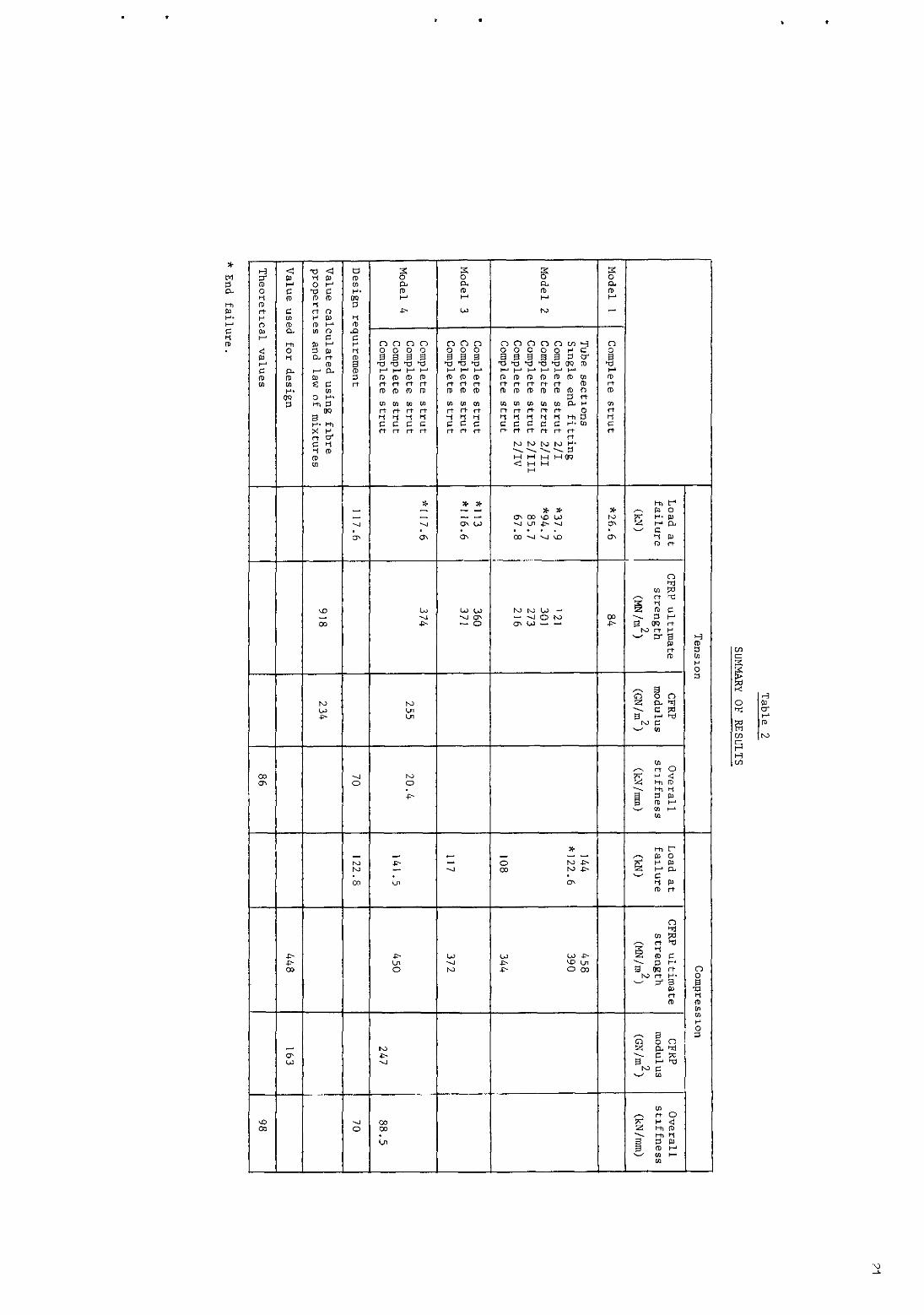
The flnal CFRP strut (model 4) weighed 43% less than the enstIng steel
component, and the quant=tatl"e results are summarised ln Table 2.
18
Both the strength and stiffness of the complete strut in compression
were satisfactory. The values of compressive strength assumed in the original
design, the values obtained from small tube sections and the value obtained
from a complete model 4 strut all agreed closely. Strut failures in com-
pression showed no sign of overall buckling, did not appear to be influenced
III any way by the ends, and the design compressive load was achieved comfort-
ably. The CFRP tube compressive modulus and the overall compressive stiffness
of the strut exceeded the value assumed m design and the design requrement
respectively. It appears therefore that the method of design, and UJ part=-
cular the form of end attachment, would be satisfactory for a compression
member of this kind.
The tensile results were less encouragmg. The model 4 strut failed in
tension at exactly the design requirement value, but the failure occurred in
the end fitting at a load correspondmg only to an estimated 41% of the
ultmate tensile strength of the main CFRP tube. It was clearly establlshed
that the end failure was caused by the transverse compressive stress in the
flared end of the CFRP tube, and an estmate of the value of this stress at
failure agreed quite well with independent measurements of the transverse
compressive strength of the material. The tensile modulus of the CFRP tube
was slightly higher than expected, but the overall strut stiffness was well
below the design requirement value. This inadequacy was shown to be a con-
sequence of the lo" transverse compressive modulus of the CFRP. Under ten-
slle loads lower than that precipitating transverse compressive failure in
the CFRP flared end, the low transverse compressive modulus permits rela-
tively large radml elastic strams which, because of the small wedge angle,
lead to large corresponding axial movement wlthin the end fitting. Both the
strength and stiffness of the end flttlng are therefore limited m tensIon
by the transverse compressive performance of the CFRP. There does not
appear to be a great deal of scope for mprovement, either in the matema
properties which affect thrs performance or m detalled design, and this
type of end design 1s not therefore generally suitable for a component of
this kind designed to carry tensile loads. A more promising approach would
seem to be an adaptatmn of the shun ,omt concept. This mght take the
form of a number of concentric cylmdrical metal shms bonded between layers
of CFRP at each end of the tube and drilled to take loading pins. An end
attachment of this kind in plane form has given ultimate tensile strength
efficiencies much higher than that achieved in the work reported here, and
its stiffness should not be limited by the transverse propertIes of CFRP.
19
.
several interesting lessons were learned during the course of the work, among them the reduction in fibre ultimate tensile strength caused by ar oxida- tmn surface treatment under certain conditions, and the importance of accurate fit of the end attachment components to avoid stress concentrations as far as
possible.
Some aspects of the design were considered only partially or not at all. The provision of some torsional strength and handling integrity by means of a hellcally wound core was demonstrated only qualitatively, but no difficulty can be foreseen III using the technique III a real design. Fretting could
clearly be a problem in the end components and was taken account of III the work reported here only by bonding the CFRP tube to the metal fittings with an adhesive to prevent surface fibre damage. Methods of protection against corro-
soon between the aluminium alloy end fittings and the CFRP tube were not con- sidered and no fatigue measurements were made.
Overall, the exercise has demonstrated quantitatively the weight saving
potential of CFRP in compression struts of this kind and has contributed to
the solution of the difficult problems of attachment and load diffusion which the use of CFRP in highly anisotropic form presents.
.
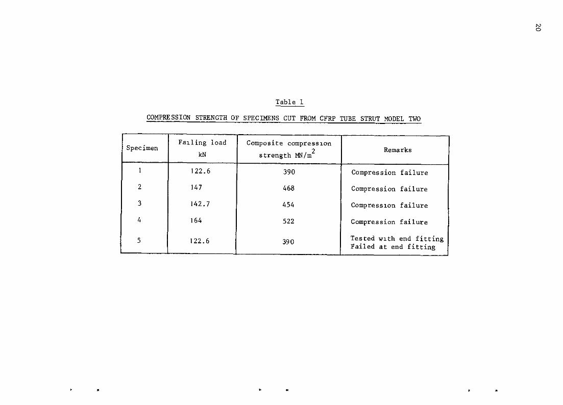
Table 1
COMPRESSION STRENGTH OF SPECIMENS CUT FROM CFRP TUBE STRUT MODEL TWO
Falling load
4 I
164
5 122.6 I Composite compressmn
strength MN/m2 Remarks
390 Compression failure
468 Compression failure
454 Compressmn failure
522 Compression failure
390 Tested with end fitting Failed at end fitting
, .
19
.
Several interesting lessons were learned during the course of the work,
among them the reduction in fibre ultimate tensile strength caused by air oxida-
tion surface treatment under certain conditions, and the importance of accurate
fit of the end attachment components to avoid stress concentrations as far as
posslble.
Some aspects of the design were considered only partially or not at all.
The provislon of some torsional strength and handling integrity by means of a
helically wound core was demonstrated only qualitatively, but no difficulty
can be foreseen in using the technique in a real design. Fretting could
clearly be a problem in the end components and was taken account of in the work
reported here only by bonding the CFRP tube to the metal fittings with an
adheslve to prevent surface fibre damage. Methods of protectIon against corro-
sion between the aluminium alloy end fittings and the CFRP tube were not con-
sidered and no fatigue measurements were made.
Overall, the exercise has demonstrated quantitatively the weight saving
potential of CFRP III compression struts of this kind and has contributed to
the solution of the difficult problems of attachment and load diffusion which
the use of CFRP in highly anisotropic form presents. .
.

Table 1
COMPRESSION STRENGTH OF SPECIMENS CUT FROM CFRP TUBE STRUT MODEL TWO
Zpecimen Falling load Composite compression
Remarks kN strength MN/m*
I 122.6 390 Compression failure
2 147 468 Compression failure
3 142.7 454 Compressx~n failure
4 164 522 Compression failure
5 122.6 390 Tested with end flttlng Failed at end fitting
23
NO. - I
2
Author
T.A. Collmgs
T.A. Collmgs
R.G. Finbow
N.3. Wadsworth
w. watt
T.A. Collings
P.D. Ewms
T.A. Collmgs
T.A. Collings
REFERENCES
Title, etc.
Compression tests on struts made from a glass fibre
composite.
Unpublished MOD(PE) materlal
Variatmn of Young's modulus with fibre vo1~~11e fraction
III unldlrectlonal carbon fibre reinforced plastic.
RAE Technical Report 70006 (1970)
The College of Aeronautics (Department of Aircraft
Design) Stressmg Data Sheets, September 1961
Some preliminary experiments on improvIng the bond
strength between RAE carbon fibres and resin.
Unpublished MOD(PE) material
RAE Technical Report to be published
Unpublished MOD(PE) material
RAE Technxal Report to be published

Reaction strut
Outer aileron
Fig.2 Position of strut in aircraft
S$ear pin
Fig.3 Attachment of strut to aircraft .
-
Tens/ion overwind
“t Compression member
Section on AA
-
----_
----_ ----
i
Fig.4 GRP strut
. . ” .
H -E 0 9
494 8mm d .
35.6mm
Fig.6 CFRP tube for struts models one and two
0, .- IL
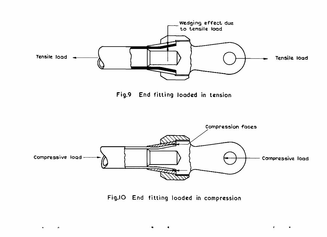
Wedging effect due to tensile load
Tensile load Tensile load
Compressive load
Fig.9 End fitting loaded in tension
Compression faces
Fig.10 End fitting loaded in compression
Compressive load
. 1 . * .
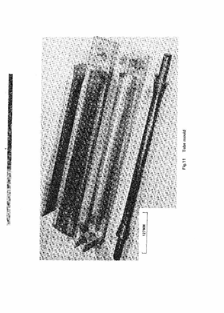
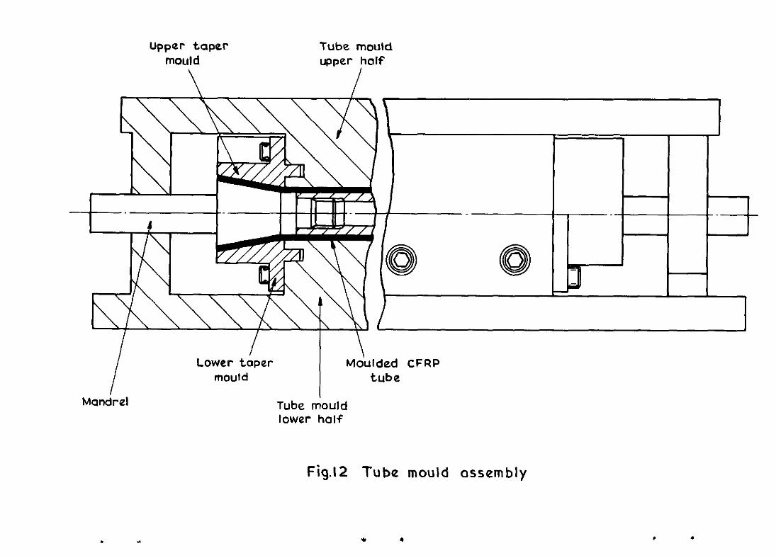
Upper taper mould
Tube mould upper half
l I I \ I
Mandrel
Lower &per Mdulded CFRP mould tube
Tube mould lower half
Fig.12 Tube mould assembly
. * * * * .

. ”
Eye end
I
ClampIng rang
I CFRP tube
I
/ \ Lntral spigot
Tenston plug L Splnt collet
Fig. 15 Strut assembly of CFRP strut model two
Ends cast from
epoxy resin MY 753
hardaner HY 951
Speciman
rquarc w&h tube
aKlr
, , End faces machined ’ End faces machined ’
rquarc w&h tube
aKlr 57mm dla d Y 1 57mm dla 1
Fig. 19 Compression test specimen
\ -_
\
\
\
LB
al I N
a LL
c
m c .- L
NY PO01
L 0
-u
H
r * .- 3 c .-
b .-
N? P-01
* . . a-
I I I , t I 1 -0 I -02 -0-3 -0 4 -0 5 -06 -0.7
Extansion mm
Fig.40 Variation of extension (-ve) with load for
strut assembly loaded in compression

P
T
DESIGN DEVELOPMENT OF AN AIRCRAFT STRUT IN CARBON FIBRE REINFORCED PLASTIC
An actuator reacnon strut from the VC 10 axle1011 power control cncut, made from steel, has hecn redeslgncd, made and tested ,n carbon fibre rclnforccd pksttc (CF RP) wtb al”mln,“m ““oy ends, partly fo demonstrate the we@” savmg potenti of CFRP t” tbts
e of apphcati0* and partly to “westlgate some of ,hb ptobtems of ,ot”tl”g and toad !&S,O” whtch CFRP presents
The ~tmt has overall ama, strength and stdf”ess requttements t” both tensto” and com- presslo” A” have bee” me, wtb the redesigned CFRP s”‘“, “‘“b the exceptlo” of tensde sttffness, the low nd”e of wb,ch was shown to be fvndamental to the form of end attach- ment adopted
?ha Report desaks the des, f
n, fabncabo” and testing af the CFRP stt”, whtch weighed 43% less than the onglnal stee component
ARC CP No 1229 Febtuaty 1972
DESIGN DEVELOPMENT OF AN AIRCRAFT STRUT ,N CARBON FlBRE REINFORCED PLASTIC
A” actuator reactlo” strut from the VC! 10 atkron power controt cucu,,, ma*e from steel, has be”” tedeslgned, made and tested 1” carbon fibre reinforced plashc (CFRP) w,th a,u,,,,“,“m alloy ends, par,,,’ to demonstrate the ,wBht s?vmg potenual of CFRP m 0”s ty d B
c of appbccatro” and partly to tnvestlgate some of the problems of ,o”“,“B and load fuslo” whtch CFRP presents
Ihe stl”t has overa,, aual strength and sbffness req”“eme”ts t” both tensto” and corn- p~esslo” AU have been me, w,,h the redesyled CFRP str”, wtth the exceptto” of tbnsd” s,tff”ess, the low value of whtch was show” to be fundamentaf to the form of end attach- ment adopt.?*
‘““s Report descnbea the de” n, fabr,cat,on and testing of the CFRP strut whtch wet&d 43% less th?” the OIwml stee k compa”e”t
, - - - - - _ -Cuthere- -
1 ARC CP No 1229
/ February 1972
I I Colh”ss,T A
1 DESIGN DEVELOPMENT OF AN AIRCRAFT STRUT 1 IN CARBON FIBRE REINFORCED PLASTIC
I An actoato~ reacbon strut from the VC 10 adaon owet control cttc”“, made from , steel, has been redes@“ed, made and tesfed III carbon ,bre ret”forced plasbc (CFRP) w,tb F 1 d”m”“um alloy ends, partly to demo”stI”,” the weigh, sa”t”g potential of CFRP m this I type of appkcah”” and partly to mv”st@e some of the problems of ,ot”b”~ and load 1 dlffuson wbtch CFRP presents
The sti”, has overall “xl”, mength and shffness tequuements “t both tensm” and com- presslo” A” have bee” me, wttb the tedeslgned CFRP stf”t wtb the exceptlo” of tend” sttffness, the low valve ofwhtch was show” to be fundamental fo the fo”” of end attach- ment adopted
Th,s Report descttts the dew”, fabncatto” and testmp of fhe CFRP sti”, whxh wet&d 43% less than the o”@“af steel component
- ’ _ -Cuthere- - --- - ---- - --- -- DETACHABLE ABSTRACT CARDS DETACHABLE ABSTRACT CARDS 1
/


C.P. No. 1229
PUbhdxd by HER MAJESTY’S STATIONERY OFFICE
To be purchased from 49 High Holborn, London WC1 ” 6HB 138 Castle Street, Edmburgh EH2 3 4R
109 St Mary Street, Cardiff CFI 1JW Brazennose Street,ManchesterM60 SAS
50 Farfax Street, Bristol BSl 3DE 258 Broad Street, Blrmmgham B1 2HE 80 Chxhester Street, Belfast BT1 4JY
or throu& booksellers
C.P. No. 1229
SBN 11 470787 1