Embed Size (px)
Citation preview
International Journal of Engineering Science Invention
Volume 1 Issue 1 ǁ December. 2012
Design & Development of Rotary Fixture for CNC N. P. Maniar
1, D. P. Vakharia
2
1Mechanical Engineering Department, Dharmsinh Desai University, India 2Mechanical Engineering Department, Sardar Vallabhbhai National Institute of Technology, India
ABSTRACT : Various areas related to fixture are already been described by renowned authors, still there is an urgent need to apply all these research works to an industrial application. This paper presents design and development of rotary fixture for real industrial component. The component is Flow TEE body of petroleum refinery. The operations to be performed are front facing, outside diameter turning, grooving, boring and back facing. Actually HMC is the best solution for performing the required operations, but HMC costs around 12.5 million rupees whereas CNC turning centre costs only about 2.5 million rupees. A fixture is designed which can be mounted on CNC turning centre and 10 million rupess are saved in installation cost as these operations can now be performed on CNC turning centre using the designed fixture. Methodology for mass balance of rotary fixture developed by investigators mostly act as post-mortem tool; calculating unbalanced mass after fixture is manufactured. In the present work, a pre-mortem tool is developed to predict unbalanced mass well before manufacturing. The present research also proposes alternate methods for mass balancing of rotary fixture. The paper sets the classical example of integrated approach of design for manufacturing.
Keywords ––CNC (Computerized numerical control) turning centre, design, HMC (Horizontal machining centre), mass balancing, rotary fixture
I. INTRODUCTION The machine tool industry has undergone sufficient changes as the requirement of user engineering
systems changed; first it started with the manufacture of basic general purpose machine tools. These machines
though offered higher flexibility were not suitable for mass production owing to longer set up times and the
tedious adjustments of machine and tools besides requiring highly skilled operators. With growing need of fast
production to meet the requirements of industry, mass production machines are conceived. Hydraulic, tracer
control machine tool, special purpose automatic and semi-automatic machines were introduced with the
advancement of technology. These machines were highly specialized but inflexible. The use of these machines
was with a success for mass production and they have considerably reduced the production costs by way of
reduced machining times and labor costs.
Because of inflexibility these machine tools could not however be adopted by units involved in small
lot and piece production. Because of the above, great need is felt for tools that could bridge the gap between
highly flexible general purpose machine tools (which are not economical for mass production) and highly
specialized, but inflexible mass production machines. Numerical control machine tools with proper fixture set
up have to take up this role very well. And this has excited this research work on design and development of
rotary fixture for CNC. The fixture designing and manufacturing is considered as complex process that demands the
knowledge of different areas, such as geometry, tolerances, dimensions, procedures and manufacturing
processes. While designing this work, a good number of literature and titles written on the subject by renowned
authors are referred. All findings and conclusions obtained from the literature review and the interaction with
fixture designers are used as guide to develop the present research work. As stated by Koji Teramoto, Masahiko
Anasoto and Kazuaki Iwata [1], Fixturing Plan (FP) and Machining Plan (MP) are mutually dependent. Implicit
to this conclusion, paper coordinates MP and FP by coupling a fixture design with manufacturing considerations
and mass balancing.
For this research, a relevant issue when considering requirements, taking this as a general concept, is to
make explicit the meaning of two main terms: Functional Requirement (FR) and Constraint (C) [2]. Functional
Design & Development of Rotary Fixture for CNC
Requirement (FR), as it stated by different authors, „represents what the product has to or must do independently
of any possible solution‟. Constraint (C) can be defined as „a restriction that in general affects some kind of
requirement, and it limits the range of possible solutions while satisfying the requirements‟. Though some
contributions have been made in several areas related to design of fixture like knowledge model for fixture
design process, workpiece location, computer aided fixture design, fixture analysis under dynamic machining
etc. [3-8], but there is a great deal of urgency and importance to couple all these research works to an industrial
application. This paper reviews all these research works and transforms the theoretical knowledge of fixture
design to practical application.
The balancing of mechanisms is motivated by continuous interest machine designers express in the
solution of problems concerning prevention of noise, wear and fatigue generated by the transmission of
unbalanced shaking forces and shaking moments to the frames and foundations of machines. It generally
confines itself to the shaking force and shaking moment balancing, full or partial, by internal mass
redistribution or counterweight addition. However, the complete shaking force and shaking moment
balancing problem is very complicated. Often in practice, the problem of mass balancing is limited by
full force balancing and partial moment balancing [7].
Methodology for mass balance of rotary fixture developed by investigators mostly act as post-mortem
tool; calculating unbalanced mass after fixture is manufactured. In the present work, a pre-mortem tool is
developed to predict unbalanced mass well before manufacturing. Step by step procedure for mass balancing of
fixture is proposed with the innovative approach of use of Creo Elements/Pro 5.0. The present research proposes
alternate methods of IV Quadrant and VIII Quadrant Computer Aided Mass Balancing Method (CAMBM) for
mass balancing of rotary fixture.
The important details of the part and fixture are included in each fixture design section for clarifying
doubts in addition to component drawing & fixture drawing. The research work includes the 3D assembled &
exploded view of fixture using Creo Elements/Pro 5.0. Fixture is mass balanced using Pro/Mechanism. The
object of work presented here is to develop the study and to provide the optimum conditions of design
and development of rotary fixture for CNC.
II. DESIGN & DEVELOPMENT OF ROTARY FIXTURE
2.1 Statement of Problem
“Design & development of rotary fixture for machining flow TEE body on CNC turning centre. The
operations to be performed are front facing, outside diameter turning, grooving, boring and back facing. The
fixture being rotary in nature has to be mass balanced.”
2.2 Component details
The methodology proposed for design of a fixture includes the realization of two stages. The first stage
represents the knowledge of the objects like part geometry, machining process, functional and detailed fixture
design, and fixture resources. The second stage describes the inference process (design and interpretation rules)
needed to obtain a first solution for the machining fixture [3].
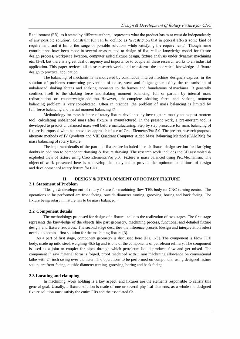
As a part of first stage, component geometry is discussed here [Fig. 1-3]. The component is Flow TEE
body, made up mild steel, weighing 46.5 kg and is one of the components of petroleum refinery. The component
is used as a joint or coupler for pipes through which petroleum liquid products flow and get mixed. The
component in raw material form is forged, proof machined with 3 mm machining allowance on conventional
lathe with 24 inch swing over diameter. The operations to be performed on component, using designed fixture
set up, are front facing, outside diameter turning, grooving, boring and back facing.
2.3 Locating and clamping
In machining, work holding is a key aspect, and fixtures are the elements responsible to satisfy this
general goal. Usually, a fixture solution is made of one or several physical elements, as a whole the designed
fixture solution must satisfy the entire FRs and the associated Cs.
Design & Development of Rotary Fixture for CNC
Figure 1. Finished Component Drawing
Figure 2. 3D view of raw material of component
Figure 3. 3D view of finished part
Centering, locating, orientating, clamping, and supporting, can be considered the functional
requirements of fixtures. In terms of constraints, there are many factors to be considered, mainly dealing with:
shape and dimensions of the part to be machined, tolerances, sequence of operations, machining strategies,
cutting forces, number of set-ups, set-up times, volume of material to be removed, batch size, production rate,
machine morphology, machine capacity, cost, etc. At the end, the solution can be characterized by its:
simplicity, rigidity, accuracy, reliability, and economy [2]. Workpiece location in a fixture is significantly
influenced by localized elastic deformation of the workpiece at the fixturing points. These deformations are
caused by the clamping force(s) applied to the workpiece. For a relatively rigid workpiece, the localized elastic
deformations cause it to undergo rigid body translations and rotations which alter its location with respect to the
cutting tool. It is therefore important to minimize such effects through optimal design of the fixture layout [4].
S. K. Hargrove and A. Kusiak [5] recognize four general requirements of a fixture: (i) Accurate
location of the workpiece, (ii) Total restraint of the workpiece during machining, (iii) Limited deformation of
the workpiece, (iv) No machining interference. In addition, as set forth by R. T. Meyer and F. W. Liou [6],
dynamic machining conditions occur when a workpart is subject to machining forces that move through the
work part or along its surface. A viable fixture designed for a workpart experiencing dynamic machining must
ensure: the workpart is restrained for all time, the clamping forces are not too large or small, deterministic
positioning, accessibility, stability of the workpart in the fixture while under no external forces, and a positive
clamping sequence.
Workpiece motion arising from localized elastic deformation at the workpiece/fixture contacts due to
machining and clamping forces significantly affect the workpiece location accuracy and hence the machined
part quality. The tangential friction force plays an important role in fixture configuration design as it can be
utilized to reduce the number of fixture components, thereby the workpiece features accessibility to machining
operations and providing a damping mechanism to dissipate input energy from machining forces out of the
workpiece/fixture system. Contact problems with friction are generally complicated by the fact that the contact
surface can experience slipping, sliding, rolling or tension release depending on the magnitude of the normal
and tangential forces at the contact interface [8].
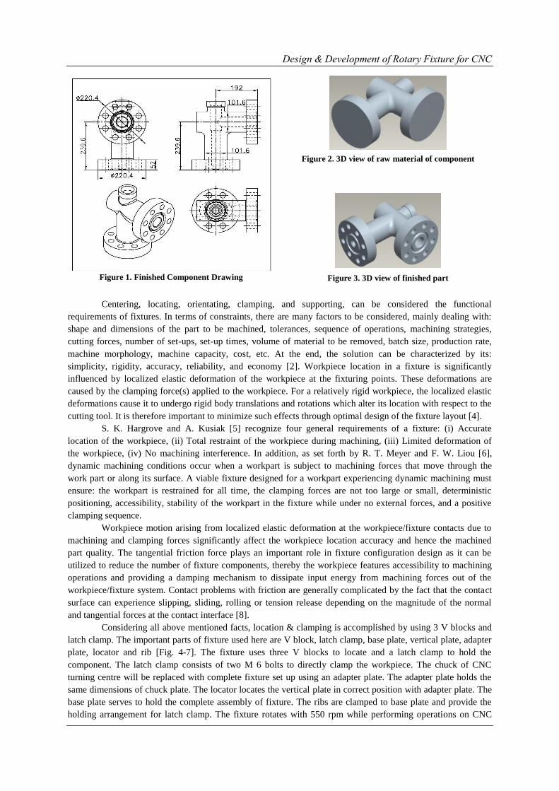
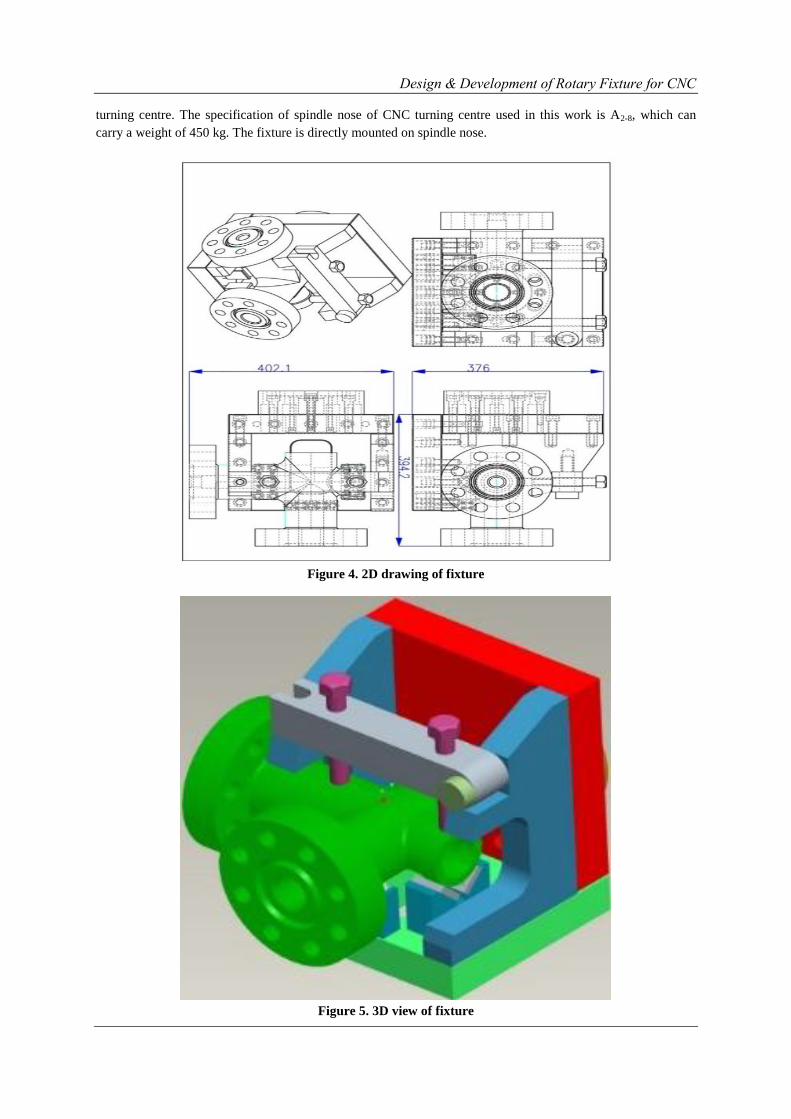
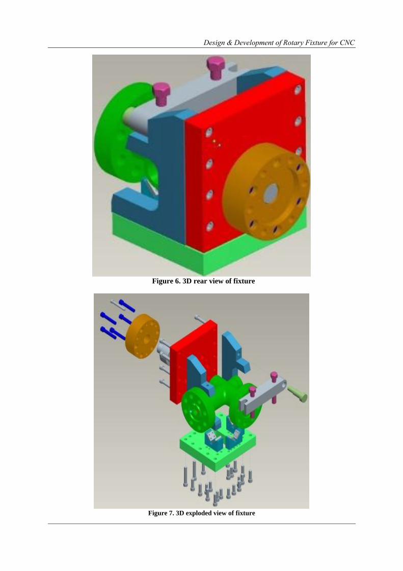
Considering all above mentioned facts, location & clamping is accomplished by using 3 V blocks and
latch clamp. The important parts of fixture used here are V block, latch clamp, base plate, vertical plate, adapter
plate, locator and rib [Fig. 4-7]. The fixture uses three V blocks to locate and a latch clamp to hold the
component. The latch clamp consists of two M 6 bolts to directly clamp the workpiece. The chuck of CNC
turning centre will be replaced with complete fixture set up using an adapter plate. The adapter plate holds the
same dimensions of chuck plate. The locator locates the vertical plate in correct position with adapter plate. The
base plate serves to hold the complete assembly of fixture. The ribs are clamped to base plate and provide the
holding arrangement for latch clamp. The fixture rotates with 550 rpm while performing operations on CNC
Design & Development of Rotary Fixture for CNC
turning centre. The specification of spindle nose of CNC turning centre used in this work is A2-8, which can
carry a weight of 450 kg. The fixture is directly mounted on spindle nose.
Figure 4. 2D drawing of fixture
Figure 5. 3D view of fixture
Design & Development of Rotary Fixture for CNC
Figure 6. 3D rear view of fixture
Figure 7. 3D exploded view of fixture
Design & Development of Rotary Fixture for CNC
III. COMPUTER AIDED MASS BALANCING METHOD (CAMBM)
FOR ROTARY FIXTURE Methodology developed by most of the researchers mostly act as post-mortem tool, calculating and
determining unbalanced mass after fixture is manufactured followed by unbalanced mass removal or
counterweight addition. A tool that could predict unbalanced mass during fixture design stage is not yet
developed. The present volume of this paper proposes the unique method of use of Creo Elements/Pro 5.0,
which would enable prediction of unbalanced mass during design stage well before manufacturing. This
approach would be highly useful in the shop floor, saving material cost, increasing the productivity and
decreasing the human labor. In this work, fixture is balanced by adding counterweight equal in magnitude and
opposite in direction as that of resultant unbalanced mass. The object of the work presented here is to
develop the study and to provide the optimum conditions of design, manufacturing, static analysis with
force & moment balancing of fixture. As the fixture is asymmetrical, it has to be mass balanced. The fixture
rotates around one axis; hence it has to be balanced about other two perpendicular axis. Here x - axis is the axis
of rotation. The results and outputs from Creo Elements/Pro 5.0 with solution of balancing are shown below.
3.1 IV Quadrant Computer Aided Mass Balancing Method
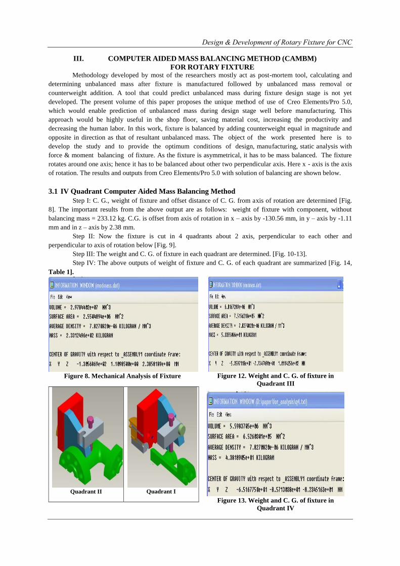
Step I: C. G., weight of fixture and offset distance of C. G. from axis of rotation are determined [Fig.
8]. The important results from the above output are as follows: weight of fixture with component, without
balancing mass = 233.12 kg. C.G. is offset from axis of rotation in x – axis by -130.56 mm, in y – axis by -1.11
mm and in z – axis by 2.38 mm.
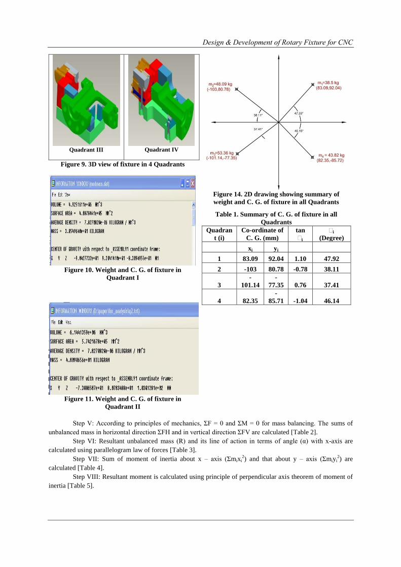
Step II: Now the fixture is cut in 4 quadrants about 2 axis, perpendicular to each other and
perpendicular to axis of rotation below [Fig. 9].
Step III: The weight and C. G. of fixture in each quadrant are determined. [Fig. 10-13].
Step IV: The above outputs of weight of fixture and C. G. of each quadrant are summarized [Fig. 14,
Table 1].
Figure 8. Mechanical Analysis of Fixture
Quadrant II
Quadrant I
Figure 12. Weight and C. G. of fixture in
Quadrant III
Figure 13. Weight and C. G. of fixture in
Quadrant IV
Design & Development of Rotary Fixture for CNC
Quadrant III
Quadrant IV
Figure 9. 3D view of fixture in 4 Quadrants
Figure 10. Weight and C. G. of fixture in
Quadrant I
Figure 11. Weight and C. G. of fixture in
Quadrant II
Figure 14. 2D drawing showing summary of
weight and C. G. of fixture in all Quadrants
Table 1. Summary of C. G. of fixture in all
Quadrants
Quadran
t (i)
Co-ordinate of
C. G. (mm)
tan
θi
θi
(Degree)
xi yi
1 83.09 92.04 1.10 47.92
2 -103 80.78 -0.78 38.11
3
-
101.14
-
77.35 0.76 37.41
4 82.35
-
85.71 -1.04 46.14
Step V: According to principles of mechanics, ΣF = 0 and ΣM = 0 for mass balancing. The sums of
unbalanced mass in horizontal direction ΣFH and in vertical direction ΣFV are calculated [Table 2].
Step VI: Resultant unbalanced mass (R) and its line of action in terms of angle (α) with x-axis are
calculated using parallelogram law of forces [Table 3].
Step VII: Sum of moment of inertia about x – axis (Σmixi2) and that about y – axis (Σmiyi
2) are
calculated [Table 4].
Step VIII: Resultant moment is calculated using principle of perpendicular axis theorem of moment of
inertia [Table 5].
Design & Development of Rotary Fixture for CNC
Table 2. Calculation of resultant mass in horizontal
direction (θFH) and in vertical direction(θFV)
Quadrant
(i)
mi
(kg)
FH=xi=miCos
θi
(kg)
FV=yi=miSin
θi
(kg)
1 38.5 25.79868396 28.57757698
2 48.09 -37.8405504 29.67727827
3 53.36 -42.38538755 -32.41555988
4 43.82 30.35986498 -31.59859171
θ -24.06738901 -5.75929635
Table 3. Calculation of Resultant Force, R
ΣFH2 579.2392137 kg
2
ΣFV2 33.16949445 kg
2
ΣFH2 + ΣFV
2 612.4087082 kg
2
Resultant, R = √ (ΣFH2 +
ΣFV2) 24.7468929 kg
tan α 0.23929876
α 13.45773737º
Table 4. Calculation of sum of moment of Inertia
about X – direction (θmixi2) and that of about Y –
direction (θmiyi2)
Quadra
nt
(i)
mi
(kg)
mixi2
(kg mm
2)
miyi2
(kg mm
2)
1 38.5
265802.001
9 326147.4216
2
48.0
9 510186.81 313806.89
3
53.3
6
545835.426
7 319254.0806
4
43.8
2 297166.316 321910.6637
θ
1618990.55
4 1281119.056
Table 5. Calculation of Resultant Moment, M
Ixx = Σ mixi2
= 1618990.554 kg mm2
Iyy = Σ miyi2 = 1281119.056 kg mm
2
Izz = Ixx + Iyy
M = Σ mixi2 + Σ miyi
2 = 2900109.61 kg mm
2
Step IX: Having M, R and α, the location of C. G. (rcm) of R is determined.
M = R rcm2
rcm2 = M / R
rcm = 342.33 mm
Thus the unbalanced mass is found to be 24.75 kg and its C. G. is situated at an angle of 13.45o with x-
axis at a distance of 342.33 mm in quadrant III. Hence the fixture can be balanced by placing the counterweight
equal in magnitude and opposite in direction as that of unbalanced mass.
3.2 VIII Quadrant Computer Aided Mass Balancing Method
Step I: This step is same as in IV Quadrant Computer Aided Mass Balancing Method.
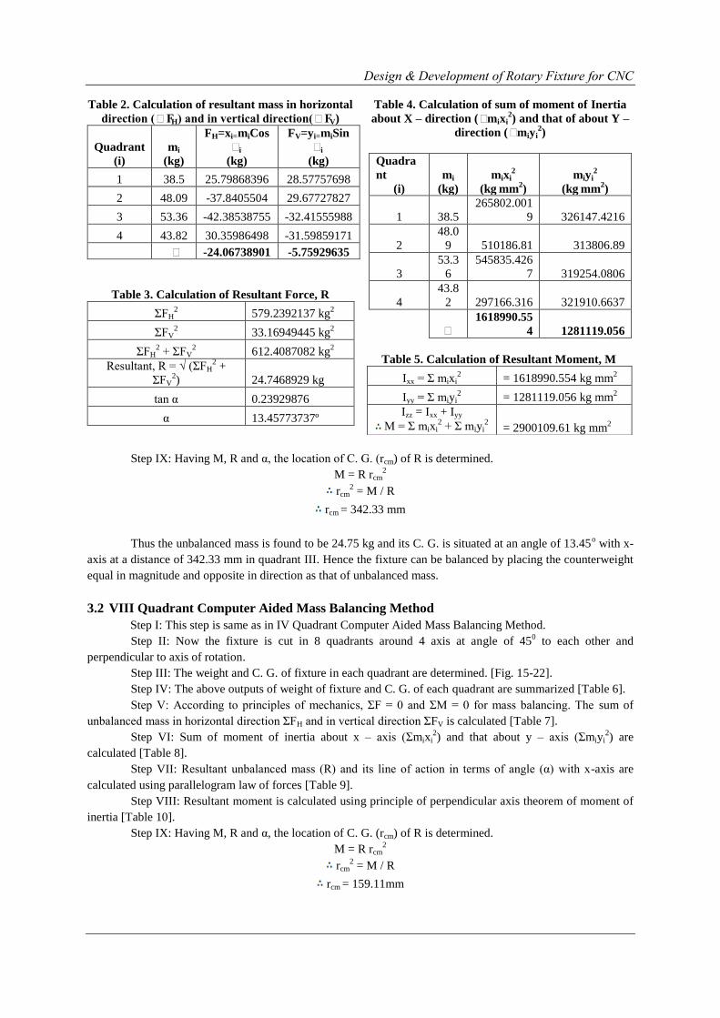
Step II: Now the fixture is cut in 8 quadrants around 4 axis at angle of 450 to each other and
perpendicular to axis of rotation.
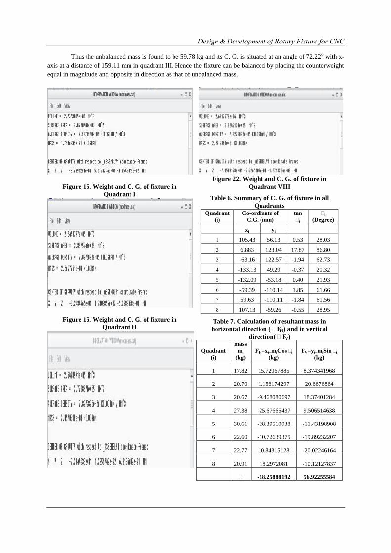
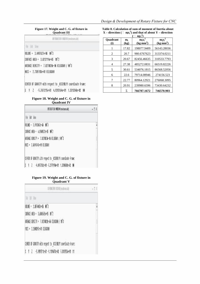
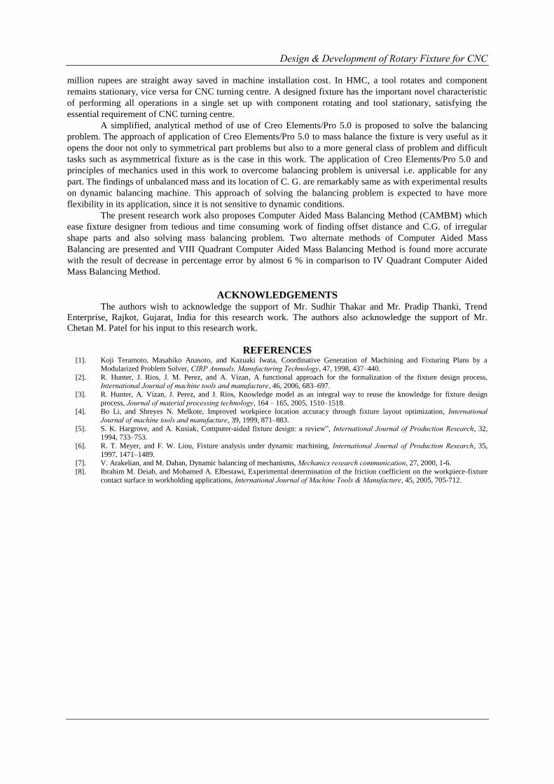
Step III: The weight and C. G. of fixture in each quadrant are determined. [Fig. 15-22].
Step IV: The above outputs of weight of fixture and C. G. of each quadrant are summarized [Table 6].
Step V: According to principles of mechanics, ΣF = 0 and ΣM = 0 for mass balancing. The sum of
unbalanced mass in horizontal direction ΣFH and in vertical direction ΣFV is calculated [Table 7].
Step VI: Sum of moment of inertia about x – axis (Σmixi2) and that about y – axis (Σmiyi
2) are
calculated [Table 8].
Step VII: Resultant unbalanced mass (R) and its line of action in terms of angle (α) with x-axis are
calculated using parallelogram law of forces [Table 9].
Step VIII: Resultant moment is calculated using principle of perpendicular axis theorem of moment of
inertia [Table 10].
Step IX: Having M, R and α, the location of C. G. (rcm) of R is determined.
M = R rcm2
rcm2 = M / R
rcm = 159.11mm
Design & Development of Rotary Fixture for CNC
Thus the unbalanced mass is found to be 59.78 kg and its C. G. is situated at an angle of 72.22o with x-
axis at a distance of 159.11 mm in quadrant III. Hence the fixture can be balanced by placing the counterweight
equal in magnitude and opposite in direction as that of unbalanced mass.
Figure 15. Weight and C. G. of fixture in
Quadrant I
Figure 16. Weight and C. G. of fixture in
Quadrant II
Figure 22. Weight and C. G. of fixture in
Quadrant VIII
Table 6. Summary of C. G. of fixture in all
Quadrants
Quadrant
(i)
Co-ordinate of
C.G. (mm)
tan
θi
θi
(Degree)
xi yi
1 105.43 56.13 0.53 28.03
2 6.883 123.04 17.87 86.80
3 -63.16 122.57 -1.94 62.73
4 -133.13 49.29 -0.37 20.32
5 -132.09 -53.18 0.40 21.93
6 -59.39 -110.14 1.85 61.66
7 59.63 -110.11 -1.84 61.56
8 107.13 -59.26 -0.55 28.95
Table 7. Calculation of resultant mass in
horizontal direction (θFH) and in vertical
direction(θFV)
Quadrant
(i)
mass
mi
(kg)
FH=xi=miCos θi
(kg)
FV=yi=miSinθi
(kg)
1 17.82 15.72967885 8.374341968
2 20.70 1.156174297 20.6676864
3 20.67 -9.468080697 18.37401284
4 27.38 -25.67665437 9.506514638
5 30.61 -28.39510038 -11.43198908
6 22.60 -10.72639375 -19.89232207
7 22.77 10.84315128 -20.02246164
8 20.91 18.2972081 -10.12127837
θ -18.25888192 56.92255584
Design & Development of Rotary Fixture for CNC
Figure 17. Weight and C. G. of fixture in
Quadrant III
Figure 18. Weight and C. G. of fixture in
Quadrant IV
Figure 19. Weight and C. G. of fixture in
Quadrant V
Table 8. Calculation of sum of moment of Inertia about
X – direction (θ mixi2) and that of about Y – direction
(θ miyi2)
Quadrant
(i)
mi
(kg)
mixi2
(kg mm2)
miyi2
(kg mm2)
1 17.82 198077.9409 56143.28036
2 20.7 980.6767623 313374.0211
3 20.67 82456.46635 310533.7793
4 27.38 485272.0831 66519.82226
5 30.61 534076.1815 86568.52056
6 22.6 79714.08946 274156.523
7 22.77 80964.12921 276068.3095
8 20.91 239980.6596 73430.64232
Σ 766787.1672 746570.903
Design & Development of Rotary Fixture for CNC
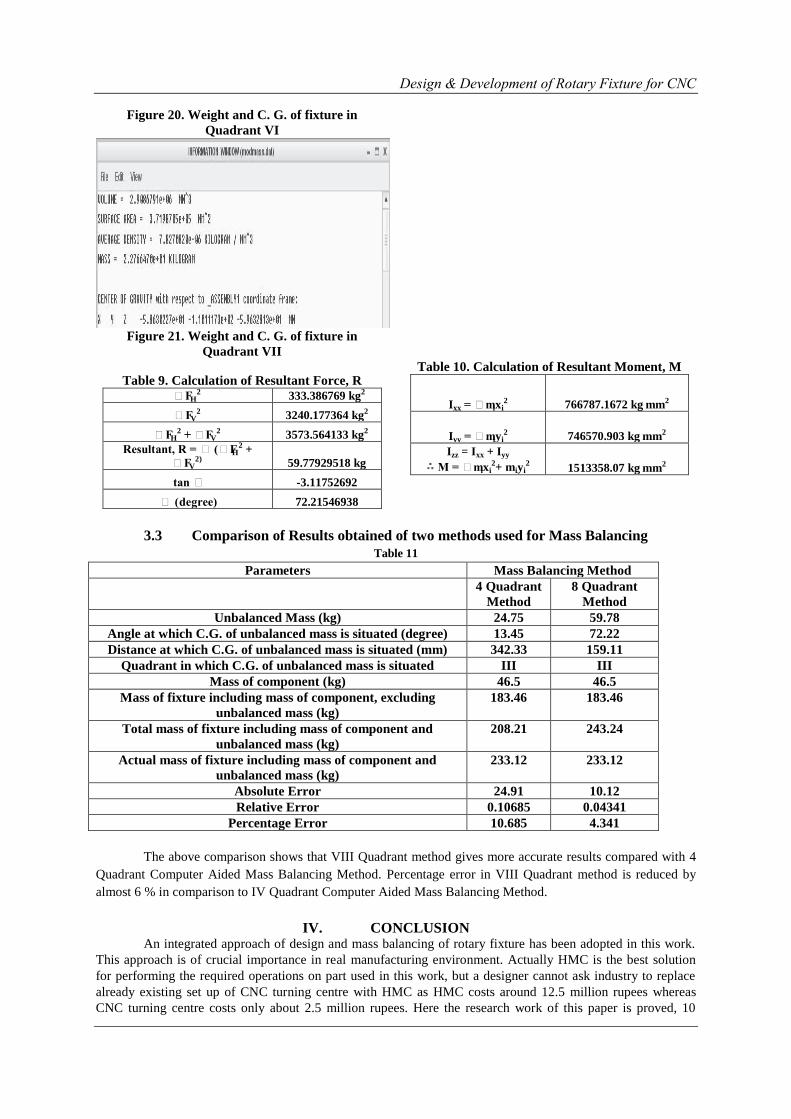
Figure 20. Weight and C. G. of fixture in
Quadrant VI
Figure 21. Weight and C. G. of fixture in
Quadrant VII
Table 9. Calculation of Resultant Force, R
θFH2 333.386769 kg2
θFV2 3240.177364 kg2
θFH2 + θFV
2 3573.564133 kg2
Resultant, R = θ (θFH2 +
θFV2) 59.77929518 kg
tan θ -3.11752692
θ (degree) 72.21546938
Table 10. Calculation of Resultant Moment, M
Ixx = θmixi2 766787.1672 kg mm2
Iyy = θmiyi2 746570.903 kg mm2
Izz = Ixx + Iyy
M = θmixi2+ miyi
2 1513358.07 kg mm2
3.3 Comparison of Results obtained of two methods used for Mass Balancing
Table 11
Parameters Mass Balancing Method
4 Quadrant
Method
8 Quadrant
Method
Unbalanced Mass (kg) 24.75 59.78
Angle at which C.G. of unbalanced mass is situated (degree) 13.45 72.22
Distance at which C.G. of unbalanced mass is situated (mm) 342.33 159.11
Quadrant in which C.G. of unbalanced mass is situated III III
Mass of component (kg) 46.5 46.5
Mass of fixture including mass of component, excluding
unbalanced mass (kg)
183.46 183.46
Total mass of fixture including mass of component and
unbalanced mass (kg)
208.21 243.24
Actual mass of fixture including mass of component and
unbalanced mass (kg)
233.12 233.12
Absolute Error 24.91 10.12
Relative Error 0.10685 0.04341
Percentage Error 10.685 4.341
The above comparison shows that VIII Quadrant method gives more accurate results compared with 4
Quadrant Computer Aided Mass Balancing Method. Percentage error in VIII Quadrant method is reduced by
almost 6 % in comparison to IV Quadrant Computer Aided Mass Balancing Method.
IV. CONCLUSION An integrated approach of design and mass balancing of rotary fixture has been adopted in this work.
This approach is of crucial importance in real manufacturing environment. Actually HMC is the best solution
for performing the required operations on part used in this work, but a designer cannot ask industry to replace
already existing set up of CNC turning centre with HMC as HMC costs around 12.5 million rupees whereas
CNC turning centre costs only about 2.5 million rupees. Here the research work of this paper is proved, 10
Design & Development of Rotary Fixture for CNC
million rupees are straight away saved in machine installation cost. In HMC, a tool rotates and component
remains stationary, vice versa for CNC turning centre. A designed fixture has the important novel characteristic
of performing all operations in a single set up with component rotating and tool stationary, satisfying the
essential requirement of CNC turning centre.
A simplified, analytical method of use of Creo Elements/Pro 5.0 is proposed to solve the balancing
problem. The approach of application of Creo Elements/Pro 5.0 to mass balance the fixture is very useful as it
opens the door not only to symmetrical part problems but also to a more general class of problem and difficult
tasks such as asymmetrical fixture as is the case in this work. The application of Creo Elements/Pro 5.0 and
principles of mechanics used in this work to overcome balancing problem is universal i.e. applicable for any
part. The findings of unbalanced mass and its location of C. G. are remarkably same as with experimental results
on dynamic balancing machine. This approach of solving the balancing problem is expected to have more
flexibility in its application, since it is not sensitive to dynamic conditions.
The present research work also proposes Computer Aided Mass Balancing Method (CAMBM) which
ease fixture designer from tedious and time consuming work of finding offset distance and C.G. of irregular
shape parts and also solving mass balancing problem. Two alternate methods of Computer Aided Mass
Balancing are presented and VIII Quadrant Computer Aided Mass Balancing Method is found more accurate
with the result of decrease in percentage error by almost 6 % in comparison to IV Quadrant Computer Aided
Mass Balancing Method.
ACKNOWLEDGEMENTS The authors wish to acknowledge the support of Mr. Sudhir Thakar and Mr. Pradip Thanki, Trend
Enterprise, Rajkot, Gujarat, India for this research work. The authors also acknowledge the support of Mr.
Chetan M. Patel for his input to this research work.
REFERENCES [1]. Koji Teramoto, Masahiko Anasoto, and Kazuaki Iwata, Coordinative Generation of Machining and Fixturing Plans by a
Modularized Problem Solver, CIRP Annuals, Manufacturing Technology, 47, 1998, 437–440.
[2]. R. Hunter, J. Rios, J. M. Perez, and A. Vizan, A functional approach for the formalization of the fixture design process, International Journal of machine tools and manufacture, 46, 2006, 683–697.
[3]. R. Hunter, A. Vizan, J. Perez, and J. Rios, Knowledge model as an integral way to reuse the knowledge for fixture design
process, Journal of material processing technology, 164 – 165, 2005, 1510–1518. [4]. Bo Li, and Shreyes N. Melkote, Improved workpiece location accuracy through fixture layout optimization, International
Journal of machine tools and manufacture, 39, 1999, 871–883.
[5]. S. K. Hargrove, and A. Kusiak, Computer-aided fixture design: a review”, International Journal of Production Research, 32,
1994, 733–753.
[6]. R. T. Meyer, and F. W. Liou, Fixture analysis under dynamic machining, International Journal of Production Research, 35,
1997, 1471–1489. [7]. V. Arakelian, and M. Dahan, Dynamic balancing of mechanisms, Mechanics research communication, 27, 2000, 1-6.
[8]. Ibrahim M. Deiab, and Mohamed A. Elbestawi, Experimental determination of the friction coefficient on the workpiece-fixture
contact surface in workholding applications, International Journal of Machine Tools & Manufacture, 45, 2005, 705-712.