Embed Size (px)
Citation preview
Tsinghua UniversityTsinghua University
Design, Fabrication and Test of MEMS Design, Fabrication and Test of MEMS Propulsion with Solid PropellantPropulsion with Solid Propellant
44th Round Table on Micro/Nano Technologies for Spaceth Round Table on Micro/Nano Technologies for SpacePresentation, May 21, 2003Presentation, May 21, 2003
Prof. You Zheng, Zhang Gaofei, Li Han, Wang Ziyang
Dr. Ren Dahai, Gao Peng
Prof. Li Baoxuan, Dr. Hu Songqi
Tsinghua Space CenterDept of Precision Instruments and Mechanology
Tsinghua University, Beijing, P.R. China
College of Astronautics Northwestern Polytechnical University
Xi’an, P.R. China
Tsinghua UniversityTsinghua University
OutlineOutline
Micro Propulsion System OverviewMicro Propulsion System Overview
Structure DesignStructure Design
FabricationFabrication
Propellant Research and CastingPropellant Research and Casting
Modeling and AnalysisModeling and Analysis
Thruster Performance PredictionThruster Performance Prediction
Tsinghua UniversityTsinghua University
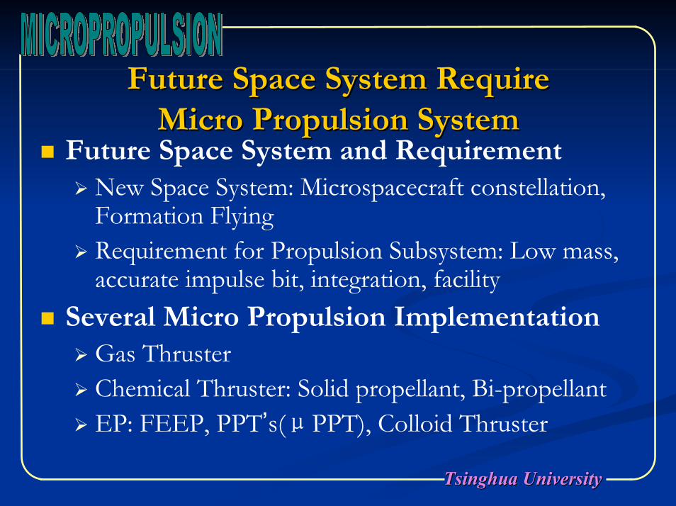
Future Space System Require Future Space System Require Micro Propulsion SystemMicro Propulsion System
Future Space System and RequirementNew Space System: Microspacecraft constellation, Formation FlyingRequirement for Propulsion Subsystem: Low mass, accurate impulse bit, integration, facility
Several Micro Propulsion ImplementationGas ThrusterChemical Thruster: Solid propellant, Bi-propellantEP: FEEP, PPT’s(μPPT), Colloid Thruster
Tsinghua UniversityTsinghua University
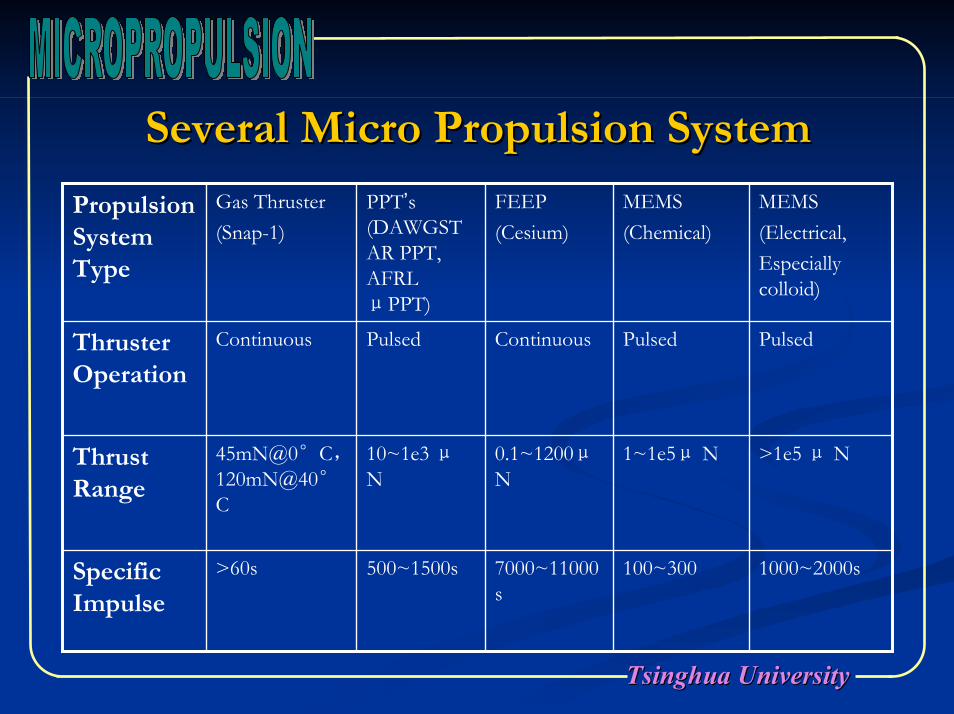
Several Micro Propulsion System Several Micro Propulsion System
1000~2000s
>1e5 μ N
Pulsed
MEMS (Electrical, Especially colloid)
100~3007000~11000s
500~1500s>60sSpecific Impulse
1~1e5μ N0.1~1200μN
10~1e3 μN
45mN@0°C,120mN@40°C
Thrust Range
PulsedContinuousPulsedContinuousThruster Operation
MEMS (Chemical)
FEEP (Cesium)
PPT’s (DAWGSTAR PPT, AFRL μPPT)
Gas Thruster(Snap-1)
Propulsion System Type
Tsinghua UniversityTsinghua University
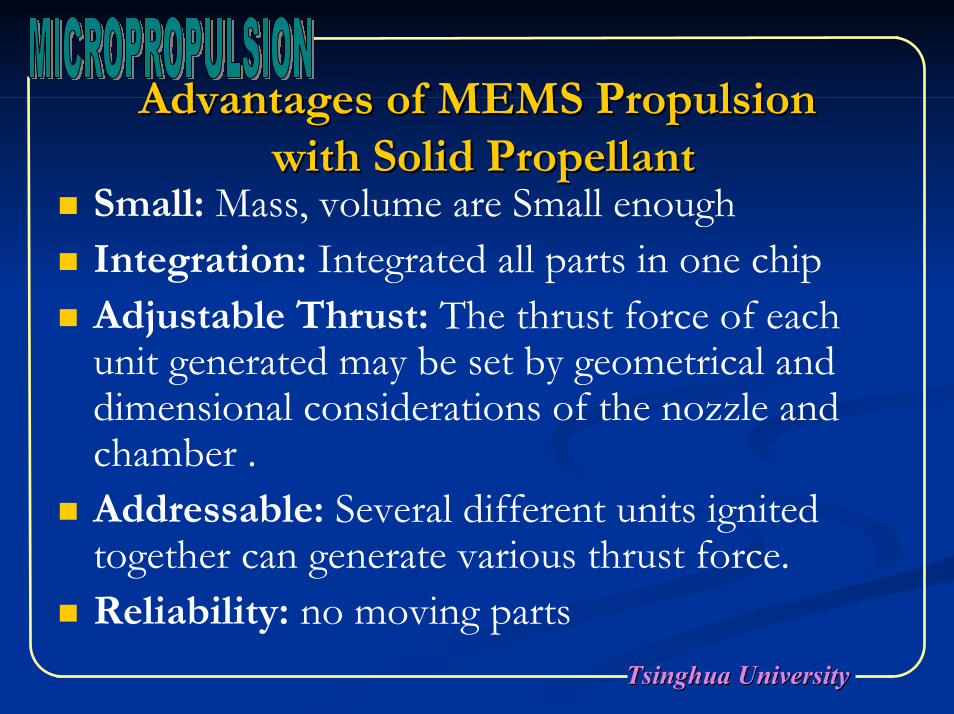
Advantages of MEMS PropulsionAdvantages of MEMS Propulsionwith Solid Propellantwith Solid Propellant
Small: Mass, volume are Small enoughIntegration: Integrated all parts in one chipAdjustable Thrust: The thrust force of each unit generated may be set by geometrical and dimensional considerations of the nozzle and chamber . Addressable: Several different units ignited together can generate various thrust force.Reliability: no moving parts
Tsinghua UniversityTsinghua University
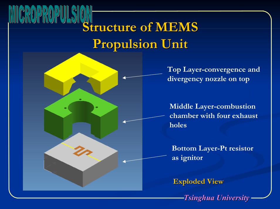
Structure of MEMS Structure of MEMS Propulsion UnitPropulsion Unit
Top Layer-convergence and divergency nozzle on top
Middle Layer-combustion chamber with four exhaust holes
Bottom Layer-Pt resistor as ignitor
Exploded ViewExploded View
Tsinghua UniversityTsinghua University
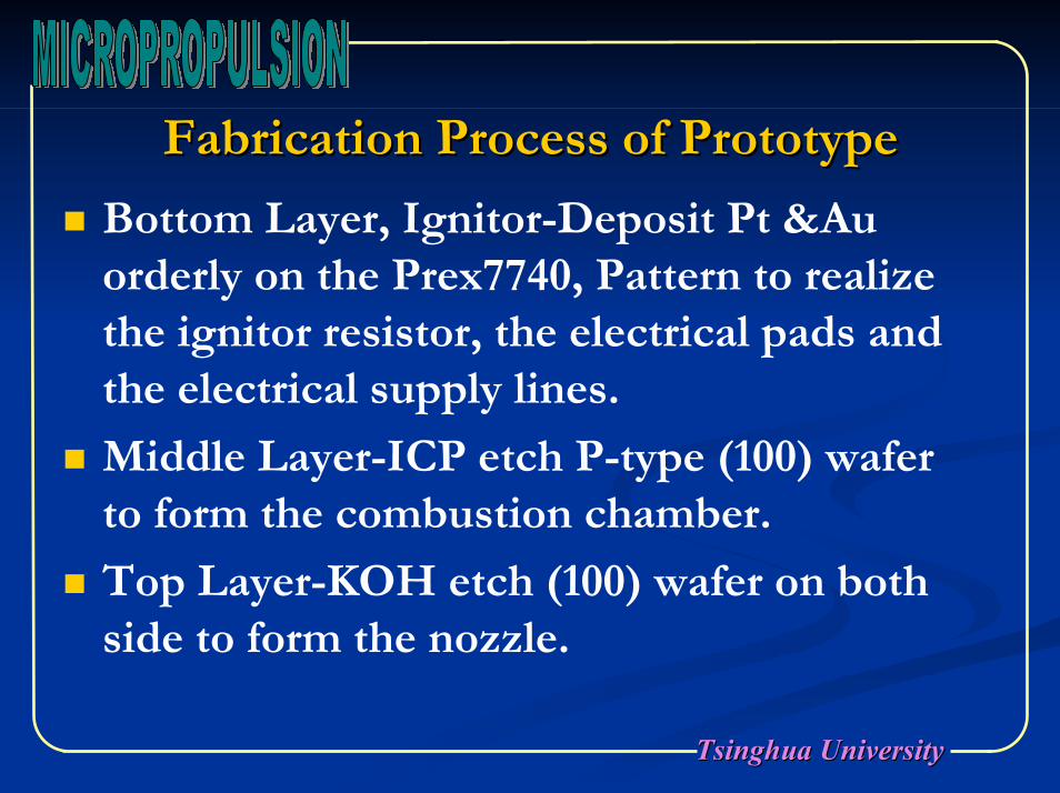
Fabrication Process of PrototypeFabrication Process of Prototype
Bottom Layer, Ignitor-Deposit Pt &Au orderly on the Prex7740, Pattern to realize the ignitor resistor, the electrical pads and the electrical supply lines.
Middle Layer-ICP etch P-type (100) wafer to form the combustion chamber.
Top Layer-KOH etch (100) wafer on both side to form the nozzle.
Tsinghua UniversityTsinghua University
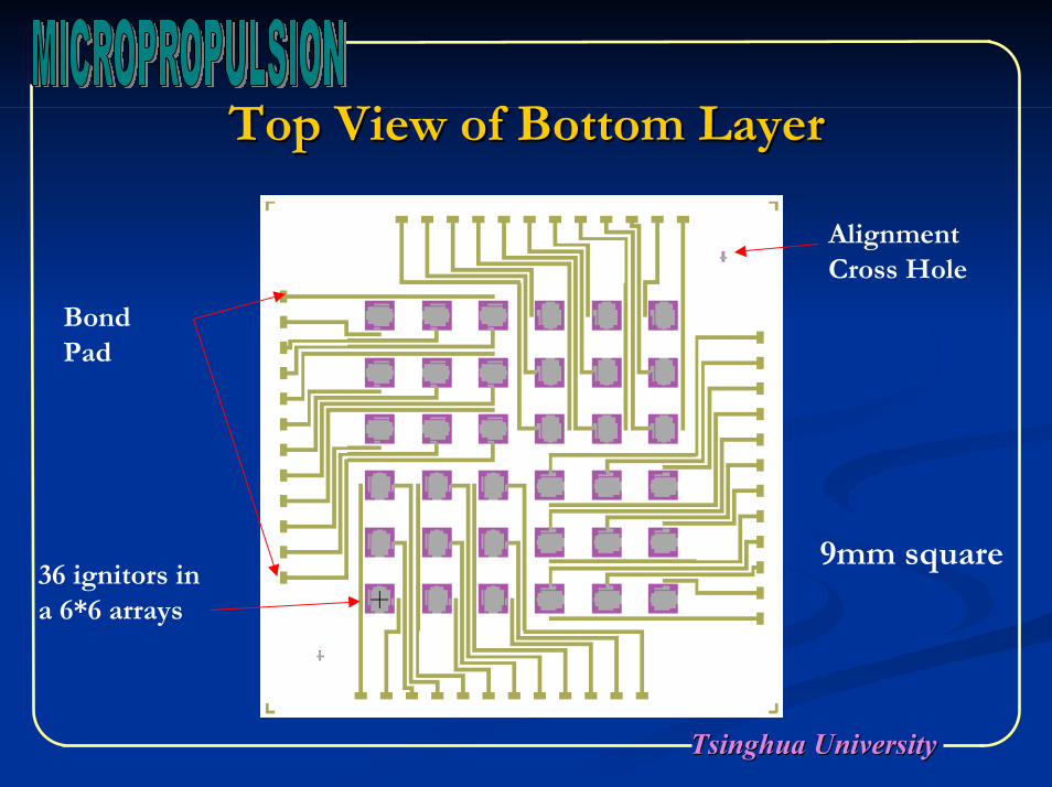
Top View of Bottom LayerTop View of Bottom Layer
36 ignitors in a 6*6 arrays
Alignment Cross Hole
Bond Pad
9mm square
Tsinghua UniversityTsinghua University
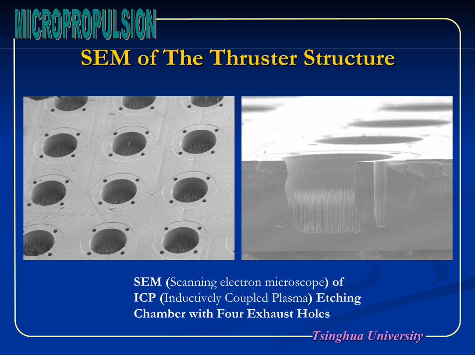
SEM of The Thruster StructureSEM of The Thruster Structure
SEM (Scanning electron microscope) of ICP (Inductively Coupled Plasma) Etching Chamber with Four Exhaust Holes
Tsinghua UniversityTsinghua University
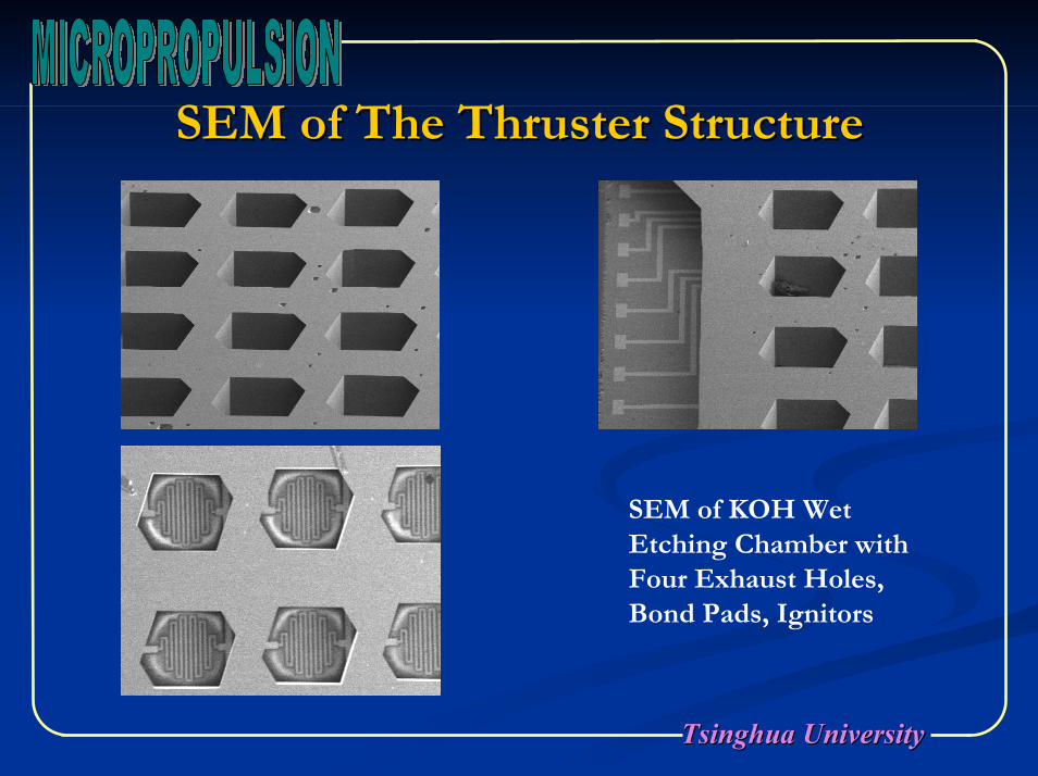
SEM of The Thruster StructureSEM of The Thruster Structure
SEM of KOH Wet Etching Chamber with Four Exhaust Holes, Bond Pads, Ignitors
Tsinghua UniversityTsinghua University
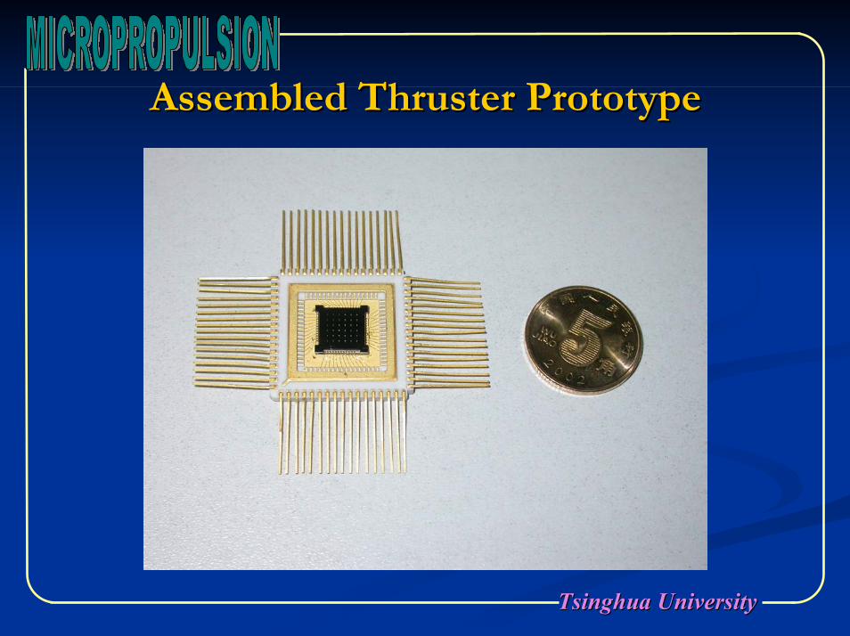
Assembled Thruster PrototypeAssembled Thruster Prototype
Tsinghua UniversityTsinghua University
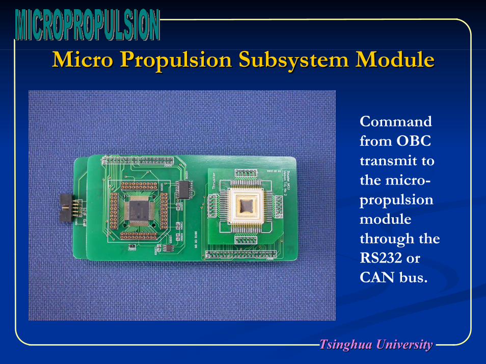
Micro Propulsion Subsystem ModuleMicro Propulsion Subsystem Module
Command from OBC transmit to the micro-propulsion module through the RS232 or CAN bus.
Tsinghua UniversityTsinghua University
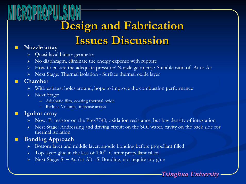
Design and Fabrication Design and Fabrication Issues DiscussionIssues Discussion
Nozzle arrayQuasi-laval binary geometryNo diaphragm, eliminate the energy expense with ruptureHow to ensure the adequate pressure? Nozzle geometry? Suitable ratio of At to AcNext Stage: Thermal isolation - Surface thermal oxide layer
ChamberWith exhaust holes around, hope to improve the combustion performanceNext Stage:
─ Adiabatic film, coating thermal oxide─ Reduce Volume, increase arrays
Ignitor arrayNow: Pt resistor on the Prex7740, oxidation resistance, but low density of integrationNest Stage: Addressing and driving circuit on the SOI wafer, cavity on the back side for thermal isolation
Bonding ApproachBottom layer and middle layer: anodic bonding before propellant filledTop layer: glue in the less of 100°C after propellant filledNext Stage: Si – Au (or Al) - Si Bonding, not require any glue
Tsinghua UniversityTsinghua University
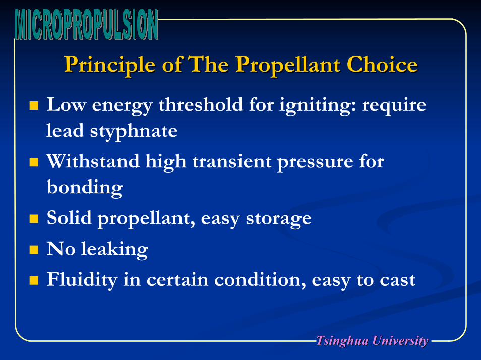
Principle of The Propellant ChoicePrinciple of The Propellant Choice
Low energy threshold for igniting: require lead styphnate
Withstand high transient pressure for bonding
Solid propellant, easy storage
No leaking
Fluidity in certain condition, easy to cast

Tsinghua UniversityTsinghua University
AA--Type Propellant Performance Type Propellant Performance SpecificationSpecification
A-type Propellant: HTPB/AP
Exponential coefficient n
Pre exponential factor a
47.43Mole Ng (mol/Kg)
21.08Mean Molecular Weight Mg (g/mol)
1.25Thermal Capacity ratio γ
0.455.52Combustion
Rate (mm/s)
1.5Specific Heat Cp
1.625Density (g/cm3)
2046Flame Temperature Te (K)
1379.4Characteristic Rate C (m/s)
ValueItem
Tsinghua UniversityTsinghua University
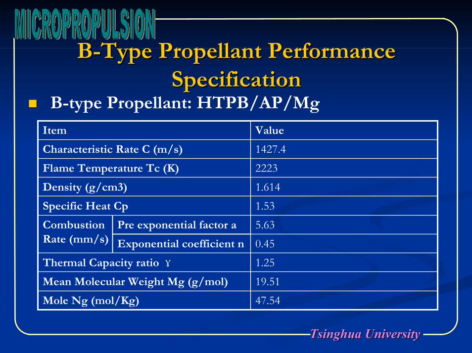
BB--Type Propellant Performance Type Propellant Performance SpecificationSpecification
B-type Propellant: HTPB/AP/Mg
Exponential coefficient n
Pre exponential factor a
47.54Mole Ng (mol/Kg)
19.51Mean Molecular Weight Mg (g/mol)
1.25Thermal Capacity ratio γ
0.455.63Combustion
Rate (mm/s)
1.53Specific Heat Cp
1.614Density (g/cm3)
2223Flame Temperature Tc (K)
1427.4Characteristic Rate C (m/s)
ValueItem
Tsinghua UniversityTsinghua University
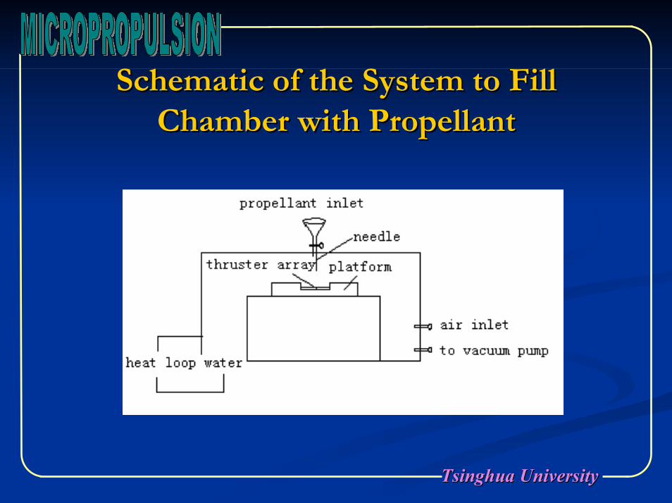
Schematic of the System to Fill Schematic of the System to Fill Chamber with PropellantChamber with Propellant
Tsinghua UniversityTsinghua University
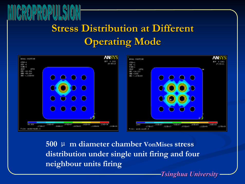
Stress Distribution at Different Stress Distribution at Different Operating ModeOperating Mode
500 μ m diameter chamber VonMises stress distribution under single unit firing and four neighbour units firing
Tsinghua UniversityTsinghua University
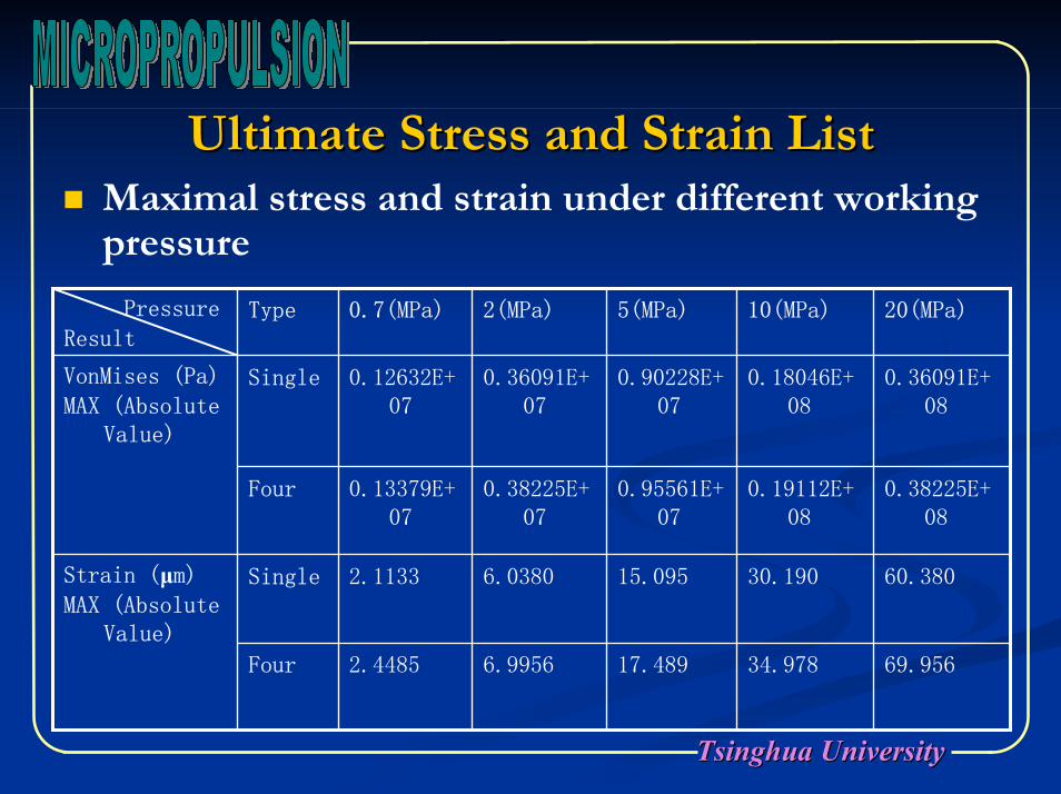
Ultimate Stress and Strain ListUltimate Stress and Strain ListMaximal stress and strain under different working pressure
69.95634.97817.4896.99562.4485Four
60.38030.19015.0956.03802.1133SingleStrain (µm)MAX (Absolute
Value)
0.38225E+08
0.19112E+08
0.95561E+07
0.38225E+07
0.13379E+07
Four
0.36091E+08
0.18046E+08
0.90228E+07
0.36091E+07
0.12632E+07
SingleVonMises (Pa)
MAX (Absolute Value)
20(MPa)10(MPa)5(MPa)2(MPa)0.7(MPa)TypePressure
Result
Tsinghua UniversityTsinghua University
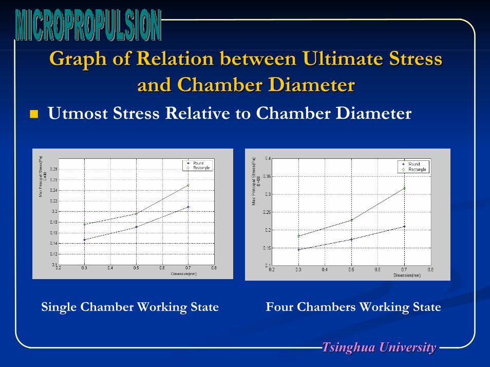
Graph of Relation between Ultimate Stress Graph of Relation between Ultimate Stress and Chamber Diameterand Chamber Diameter
Utmost Stress Relative to Chamber Diameter
Single Chamber Working State Four Chambers Working State
Tsinghua UniversityTsinghua University
Thrusts Performance PredictionThrusts Performance PredictionBasic thermodynamic principles are used, taking the following considerations
The propellant chemical reaction products are homogeneous.All the species of the working fluid are gaseous. The combustion gases follow the ideal gas law.The propellant flow is steady and constant.The chamber and nozzle wall is adiabatic.The nozzle is Laval geometry.The gases velocity, pressure, temperature and density are uniform across the section.Boundary layer effects are neglected.There is no shock waves and discontinuities in the nozzle flow.
Tsinghua UniversityTsinghua University
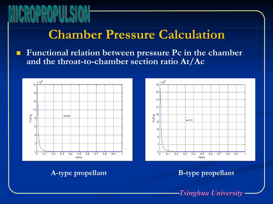
Chamber Pressure CalculationFunctional relation between pressure Pc in the chamber and the throat-to-chamber section ratio At/Ac
A-type propellant B-type propellant
Tsinghua UniversityTsinghua University
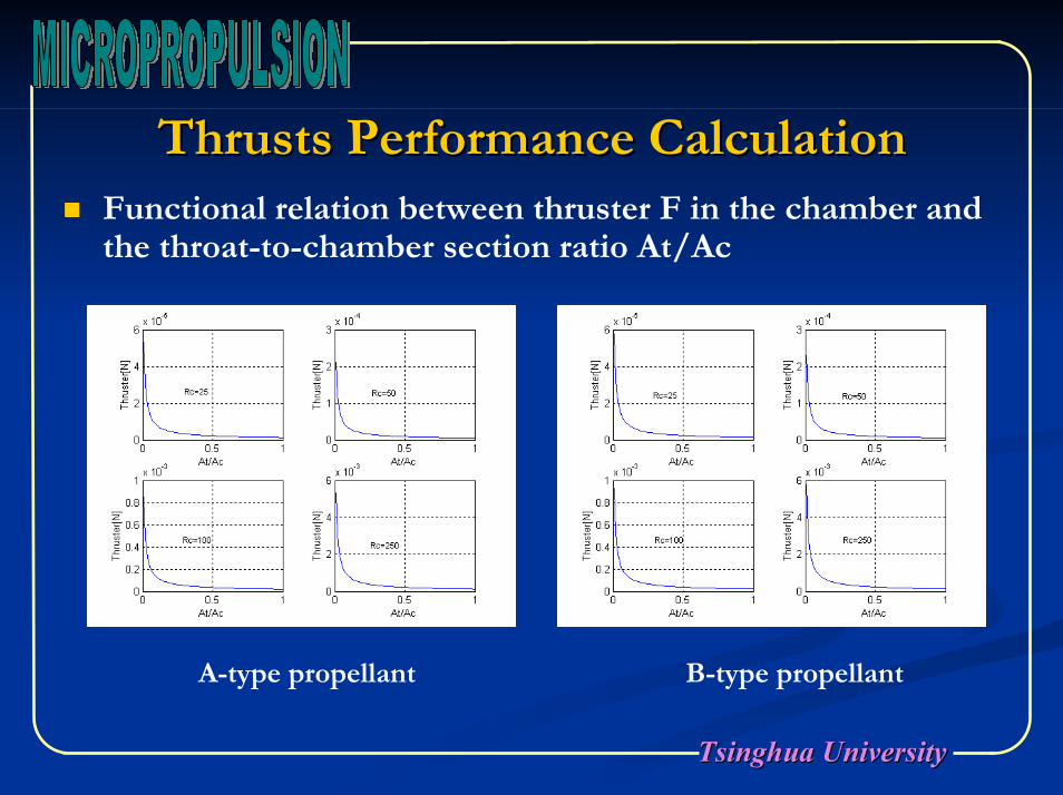
Thrusts Performance CalculationThrusts Performance CalculationFunctional relation between thruster F in the chamber and the throat-to-chamber section ratio At/Ac
A-type propellant B-type propellant

Tsinghua UniversityTsinghua University
Chamber Pressure Calculation with Increasing Chamber Pressure Calculation with Increasing Combustion RateCombustion Rate
Increasing the pre exponential factor a and the ratio Ac/At help to increase the pressure Pc
Tsinghua UniversityTsinghua University
ConclusionConclusion
MEMS solid propellant propulsion is a better option.Real thrust force and special impulse is lower than the theoretical value.Increasing the combustion rate and the throat-to-chamber section ratio is a efficient way to enlarge the thrust force.Increasing the combustion rate will improve the thruster firing performance, and ensure the combustion sufficiently.In order to increase the special impulse, thermal isolation of chamber and nozzle must be adopt.Under the micro scale condition, the boundary layer effect, thermal transfer and the propellant combustion mechanics need be further studied on.

Tsinghua UniversityTsinghua University
Team Members AddressTeam Members Address
Design and FabricationDesign and FabricationProf. YOU ZhengProf. YOU Zheng [email protected]@mail.tsinghuatsinghua..eduedu..cncnZHANG ZHANG GaofeiGaofei [email protected]@post.pim.tsinghua.edu.cn
Dr. REN Dr. REN DahaiDahai [email protected]@ntl.pim.tsinghua.edu.cn
Propellant ResearchPropellant ResearchDr. Dr. HuHu Songqi Songqi [email protected][email protected]
Department of Precision Instruments &Mechanology, Tsinghua University, Beijing 100084, P.R. China
TEL: (8610)62776000 FAX: (8610)62782308

Tsinghua UniversityTsinghua University
Thank You!Thank You!Any Comments or Suggestions Any Comments or Suggestions Will beWill be Highly Appreciated!Highly Appreciated!