Embed Size (px)
Citation preview

ARTICLE OF PROFESSIONAL INTERESTS
Design, Fabrication and Testing of Mooring Masts for RemotelyControlled Indoor and Outdoor Airships
Syed Khaleelullah1 • Utsav Bhardwaj3 • Rajkumar Sureshchandra Pant2
Received: 26 November 2013 / Accepted: 12 February 2016 / Published online: 4 March 2016
� The Institution of Engineers (India) 2016
Abstract This paper presents the design and structural
details of two mooring masts, one for remotely controlled
outdoor airships and another one for remotely controlled
indoor airships. In a previous study, a mast for outdoor
remotely controlled airship was designed to meet several
user-specified operating requirements, and a simplified
version of the same was fabricated. A spring loaded device
was incorporated that sounds an alarm when the wind-loads
exceed a threshold value, so that the airship can be taken
indoors. The present study started with a critical analysis of
that mast, and a new mast was designed and fabricated to
remove several of its shortcomings. This mast consists of
power screw operated telescopic module made of alu-
minium, mounted on a five legged base with castor wheels,
for ease in mobility. Components of the existing mast were
used to the possible extent, and the design was simplified to
meet the assembly and transportation requirements. The
spring mechanism used in alarming device was also mod-
ified to ensure higher sensitivity in the range of maximum
expected wind-loads acting on the airship. A lightweight
mooring mast for indoor remotely controlled airships was
also designed and fabricated, which can accommodate non-
rigid indoor airships of length up to 5 m. The mast consists
of an elevating bolt operated telescopic module mounted
on a tripod adapter base, with lockable castor wheels, and
has a specially designed mooring-clamp at the top. The
various modules and components of the mast were
designed to enable quick assembly and transportation.
Keywords Mooring mast � Indoor airships �Outdoor airships � Ground-handling � Yaw � Pitch �Roll
List of Symbols
L Length of the airship envelope (m)
D Maximum diameter of the airship envelope (m)
CDV Drag-coefficient based on the volume of the
envelope
v Velocity (m/s)
q Density of air at the place of flight-test (kg/m3)
l Coefficient of viscosity of air at the place of
flight-test (Pa s)
V Total volume of the envelope of airship (m3)
FDE Drag force on the bare envelope (N)
FD Drag force on the airship (N)
Syt Yield-tensile strength in tension of the material
under consideration (MPa)
Syc Yield-tensile strength in compression of the
material under consideration (MPa)
Ssy Yield-strength in shear of the material under
consideration (MPa)
M Bending moment (Nm)
T Torque (or twisting moment) (Nm)
r Stress under consideration (MPa)
rb Bending stress (MPa)
s Shear stress (MPa)
& Utsav Bhardwaj
1 Department of Mechanical Engineering, Politecnico Di
Milano, Campus Bovisa Sud - via La Masa 1, Milan 20156,
Italy
2 Indian Institute of Technology Bombay, Powai, Mumbai
400076, Maharashtra, India
3 Indian Institute of Technology Madras, Chennai 600036,
Tamil Nadu, India
123
J. Inst. Eng. India Ser. C (April–June 2016) 97(2):257–277
DOI 10.1007/s40032-016-0222-4

rn Normal stress (MPa)
rc Axial compressive stress (MPa)
Z Section modulus (m3)
F.O.S. Factor of safety
d Diameter under consideration (mm)
rt Tensile stress (MPa)
I Area moment of inertia (m4)
y Perpendicular distance of the section under
consideration from the neutral axis (mm)
HSS-1 Hollow Square Section-1 (in the mooring-mast
for indoor airships)
HSS-2 Hollow Square Section-2 (in the mooring-mast
for indoor airships)
Introduction
Airships are used for surveillance, demonstrations, pro-
duct promotion and several other commercial and scien-
tific applications. But, being buoyant and large sized, their
ground-handling is somewhat problematic. An airship
tends to have vertical oscillations while in the vicinity of
ground. So, a ground-crew is needed to ground-handle it
and this manual-handling has several drawbacks. An air-
ship is very sensitive towards atmospheric disturbances
due to its large surface-area and volume. Hence, an air-
ship should not be completely constrained (using multi-
point mooring) to move at ground in the presence of air-
gusts, so as to avoid damages to its delicate envelope and
large loads at the restraining attachments. Hence, for safe
and secure ground-handling of an airship, a structure is
proposed termed as ‘‘Mooring Mast’’. In single point
mooring, the airship is constrained only at its nose and is
allowed to yaw, pitch and roll about this point. Such a
mast enables limited three axes rotational/oscillatory
motion to the airship in moored condition, substantially
reducing the structural load due to atmospheric gusts and
random turbulence. It is also desirable to have a wind-load
measuring device on the mast (for outdoor airships), with
an alarming system to provide an aural warning to the
ground crew to move the airship and the mast inside the
storage area when the atmospheric conditions are not
suitable for outdoor storage. Mooring mast when
employed for indoor airship facilitates us in safely car-
rying the airship indoors, in mounting and demounting of
fins, any other components (e.g. a camera) on the airship
safely, by giving the freedoms of yawing, pitching, rolling
and height-adjustability to the moored airship. Howe [1]
has described the ground-handling problems of airships,
and has also outlined design features of mooring masts to
tackle them.
Critical Review of Existing Mooring Masts
Amooring mast for remotely controlled outdoor airships was
designed by Kale and Pant [2]. A critical evaluation of that
mast was carried out by Goyal et al. [3], and they observed
several shortcomings. They noticed that its structure used
different aluminium sections of varying cross sections in three
different modules, which required a lot of time and money to
fabricate. Further, they noticed that the modules had to be
madeusing amatrix i.e., the four aluminium sections had to be
fastened together in a nested fashion, demanding a lot of time
for assembly. It was felt that drilling too many holes in the
aluminium section would decrease its strength drastically.
Goyal et al. [3] then re-designed a mast with drag force
measuring device for remotely controlled outdoor airships
consisting of two modules made of aluminium sections,
clamped together using bolts. A wooden base was used and
four legswere connected to it. However, themastwas found to
be unstable since it had four legs. It was difficult to assemble
and disassemble the mast, or to adjust its height, as it needed
some bolts to be unfastened. Also, it was designed for a
maximum wind load of only 100 N, which is quite less.
Keeping in mind the shortcomings of the existing masts,
two mooring masts, one for outdoor airships and another
one for indoor airships were designed, fabricated and tes-
ted. This paper describes their design and the structural
analysis carried out for the same.
Design Requirements for Mooring Mast and DragDevice for Outdoor Airships
The design requirements for the mooring mast for outdoor
airship were arrived on the basis of the experience gained
during field trials of several remotely controlled airships,
and are summarized as follows.
The gross weight of the mooring mast should be less
than 60 kg. It should be possible to assemble or disas-
semble the mast, by two persons within 20 min. It should
fit in dismantled condition in a container placed below
berths of a long-distance train in India. Also, height from
ground should be adjustable from 1.85 to 3.00 m and it
should provide pitch freedom of ±30� and yaw freedom of
360� to the airship in moored condition.
Additionally, it was required to fit the mast with a wind-
load measuring device and alarming system, which could
display wind-load within accuracy of 100 g, and sound an
alarm when ambient wind conditions became hazardous.
Its gross weight should be less than 1 kg and it should be
easy to install it on the mast. It should not restrict the
motion of the moored airship. It should also be sensitive in
the region of expected wind-loads on the airship.
258 J. Inst. Eng. India Ser. C (April–June 2016) 97(2):257–277
123

Design of Improved Mast
Keeping inmind the above-mentioneddesign-requirements of
the mooring-mast and the drag force measuring device (with
alarming system), a mooring mast was designed and fabri-
cated as shown in the Fig. 1. The improved mast consists of
power screw operated telescopic module made of aluminium,
mountedon afive leggedbase for better stabilitywith lockable
castorwheels, for mobility. The designwas simplified tomeet
the assembly and transportation requirements.
Conceptual Design of Modified Mast
The modified mast consists of four sub-assemblies, namely:
Adapter Assembly
This assembly comprises of adapter base, mast legs and
castor wheels, and it was designed for maximum load
condition. The mast has bending tendency due to horizontal
drag force on itself and the airship. It has been estimated
that the maximum wind load of 214 N can act on a
remotely controlled outdoor airship under a wind velocity
of 25 m/s, using the formulae of drag force [4]. The
maximum bending moments at mast base were calculated
for the maximum extended height of 3 m at this wind load,
and various components of the mast were checked for their
ability to resist these bending loads. Various components of
the adapter assembly are described as follows:
Adapter Base
This is one of the most important components in the
assembly as it connects all the five legs to the power screw
operated telescopic module. Legs are fixed to the U-shaped
brackets and can be hinged or fixed depending upon the
usage as shown in Fig. 1.
Mast Legs
These are the main load bearing members, since the hori-
zontal load from wind-loads on the airship and self-weight
of the mast acts on the mast legs, from where it gets
transferred to the ground through castor wheels. The legs
were fixed to the U-shaped brackets at an angle of 10
degree for having proper ground clearance. The legs can be
folded inside the mast, making the whole mast system
compact for transportation and to reduce assembly time.
The hollow rectangular sections of the legs were placed in
a manner that they provide maximum moment of inertia
(2.85 9 10-7 m4), hence increasing the strength of the
section in bending [5]. The length of the each leg is 1.8 m,
providing adequate ground stability.
Fig. 1 CAD model (left) and photograph (right) of the modified mast for outdoor airships
J. Inst. Eng. India Ser. C (April–June 2016) 97(2):257–277 259
123

Caster Wheel Assembly
A standard 76.2 mm diameter castor wheel with load
bearing capacity of 150 kg was selected for this applica-
tion, which results in sufficient factor of safety.
Telescopic Module
This module was designed to provide ease in adjustment of
mast height from 1.85 to 3.00 m, by using a power screw.
This module consists of a square member with elevating
bolt and nut, as described.
Square Member
A square section of cast iron (as it damps vibration caused
by random turbulence of wind) was selected for satisfying
the geometrical constraints in design and ease in attach-
ment with the adapter.
Elevating Bolt and Nut
The elevating bolt was designed based on ISO standards
with square thread of pitch 6.35 mm and major diameter
of 50.8 mm [5]. Both bolt and nut were made of
Aluminum.
Gimbal Mechanism
This mechanism was designed to provide the required three
axes motion to the moored airship. This mechanism con-
sists of three components:
The Yaw Bearing Setup
This setup is made of mild steel so that it can resist the
impact loads caused due to sudden gusts or random tur-
bulence of wind. It consists of a bearing having I.D. (inner
diameter) of 40 mm and O.D. (outer diameter) of 54 mm.
It is designed in such a way that, it provides 360 degree
freedom in yaw to the airship.
Pitching Clamp
The pitching clamp provides desired freedom to the airship
in pitch axis, made of stainless steel so as to resist the
impact loads caused due to sudden gusts or random tur-
bulence of wind. The pitching clamp is attached to the yaw
bearing setup using pitching pin made of stainless steel.
Rolling Clamp
The rolling clamp provides a 360 degree freedom in roll to
the airship. This clamp carries the nose hook that is
attached to the airship nose. The crucial component of the
clamp is its mild-steel pin.
Drag Measurement and Alerting Device
A spring-operated force-measuring device was designed to
measure the drag force on the airship, as shown in Fig. 2. A
pointer attached to telescopic square section containing
spring, slides over the scale to indicate the wind-load. To
enable use of the same mast and wind-load measuring
device for larger airships or during higher ambient winds, it
Fig. 2 Drag device and gimbal
mechanism
260 J. Inst. Eng. India Ser. C (April–June 2016) 97(2):257–277
123

was decided to design the device to be capable of mea-
suring wind-loads up to 500 N. An electrical alarm system
is attached to the pointer, which gets activated if the pointer
moves beyond a particular pre-set value of wind-load.
Figure 3 shows an outdoor airship moored on this
mooring mast. Slight modifications were incorporated in
the design of nose-hook and associated sub-assembly later-
on to facilitate the attachment and rolling-freedom of the
airship, while fabrication work was being carried-out. The
airship had a length of 10.6 m and max. diameter of
2.65 m.
Table 1 provides details and illustration of the various
sub-assemblies of the mast, and lists the stresses that were
checked for relevant types of failure modes that were
expected.
Stress Analysis for Mooring Mast for OutdoorAirships
The volumetric drag coefficient CDV for an airship envel-
ope with L/D = 4 is estimated to be 0.0242, using the
empirical formula suggested by Hoerner [4].
The mooring mast should be strong enough to bear
safely the wind loads on the moored airship.
Also, q = 1.225 kg/m3 and V = 39.3 m3, hence,
FDE ¼ 1
2qV2=3v2CDV ¼ 107N
As is clear from the airships flight-tested in the past, the
drag force on the bare hull is approximately 50 % of the
drag force on the airship as a whole [6], hence, the drag
force on the airship is given by
FD ¼ 2ð107Þ ¼ 214N
Stress Analysis for Elevating Bolt
Material: Al-1060 aluminium alloy
Syt = 103 Mpa
Major diameter (d) = 50.8 mm
Thread pitch (p) = 6.35 mm
Pitch diameter (dp) = 47.625 mm
Minor diameter (dm) = 44.45 mm
Length (lb) = 1220 mm
Screw dimensions: O.D = 1.5 d and h = 0.8 d
Mass of elevating bolt = 6 kg
Lead angle [5] is given by
tan k ¼ p
pdp
tan k ¼ 6:35
ð3:14Þð47:625Þ ¼ 0:04246
k ¼ 2:43�
Lifting force required [5] is given by
P1 ¼Fðsin kþ lcoskÞcos k� l sin k
Coefficient of friction lð Þ ¼ 1:05
Force Fð Þ ¼ 60N
(including the weight of the elevating bolt itself and the
Fig. 3 Photograph of an
outdoor airship moored on the
fabricated mast
J. Inst. Eng. India Ser. C (April–June 2016) 97(2):257–277 261
123

Table 1 Design considerations for various sub-assemblies
Sub-assembly CAD model Stresses checked Type of failure Material
Elevating Bolt and Nut Bending Bolt rupture Al alloy-1060
Shear Ductile failure
Bearing Abrasive wear
Axial Impact fatigue
Adapter assembly Bending Ductile failure Mild steel
Axial
Flange and Flange bolts Bending Bolt rupture Mild steel
Shear (including fillet weld) Ductile failure
Yaw setup U-clamp and Pitch clamp Shear Bolt rupture Stainless steel
Impact Impact fatigue
Tensile
Square section Bending stress Brittle fracture Cast iron
Axial Compressive Stress
Shear stress
262 J. Inst. Eng. India Ser. C (April–June 2016) 97(2):257–277
123

mooring clamp plus drag-device installed at the top of
elevating bolt)
P1 ¼60½sin 2:43�ð Þ þ 1:05cos 2:43�ð Þ�cos 2:43�ð Þ � 1:05 sin 2:43�ð Þ
P1 ¼ 68:57N
Lowering force required [5] is given by
P2 ¼Fðl cos k� sin kÞcos kþ l sin k
P2 ¼60½1:05 cos 2:43�ð Þ � sin 2:43�ð Þ�cos 2:43�ð Þ þ 1:05 sin 2:43�ð Þ
P2 ¼ 57:86N
Torque required for lifting
T1 ¼ðP1Þ dp
� �
2
T1 ¼68:57ð Þ 47:625� 10�3ð Þ
2
T1 ¼ 1:6Nm
Torque required for lowering
T2 ¼ðP2Þ dp
� �
2¼ 57:86ð Þ 47:625� 10�3ð Þ
2
T2 ¼ 1:38Nm
Shank diameter of the elevating bolt may be used for the
design purpose without taking into account the effect of
stress-concentration [7].
Bending Stresses
Section modulus Zð Þ ¼ pd3m32
Also,
rb ¼M
Z
Now,
M ¼ 214ð Þ 1:22ð Þ ¼ 261:08Nm
rb ¼261:08
8:617� 10�6¼ 30:3MPa
Axial Compressive Stress
r ¼ F
A¼ 60
p 0:04445ð Þ2=4r ¼ 0:04MPa
Thus, the axial compressive stress due to the weight is
negligible as compared to the axial stress due to bending,
hence can be neglected in comparison with the latter.
Thus we take normal stress (rn) as
rmax:ð Þtensile¼ 30:3MPa
rmax:ð Þcompressive¼ 30:3MPa
Maximum Shear Stress
Though the torque transmission across the elevating bolt is
zero, but a lifting torque (T1) as calculated above is
required to be applied to overcome the friction. So, this
torque induces torsional shear stress in the elevating bolt.
s ¼ 16T1
pd3m¼ 16 1:6ð Þ
p 44:45� 10�3ð Þ3
s ¼ 0:09MPa
Net Stress and F.O.S
Thus, the elevating bolt is subjected to a combination of
bending and torsional moments. The principal stress and
principal shear stress can be calculated by constructing
Mohr’s circle [7]. Since the elevating bolt has been made
of Al-1060 aluminium-alloy, which is a ductile material,
hence ‘‘maximum shear stress’’ theory is applicable for its
design [7, 8].
Principal shear stress [7] is calculated as
smax: ¼
ffiffiffiffiffiffiffiffiffiffiffiffiffiffiffiffiffiffiffiffiffiffiffiffiffiffirn
2
� �2
þs2� �s
¼
ffiffiffiffiffiffiffiffiffiffiffiffiffiffiffiffiffiffiffiffiffiffiffiffiffiffiffiffiffiffiffiffiffiffiffiffiffiffiffiffiffi30:3
2
2
þ 0:09ð Þ2" #vuut
smax: ¼ 15:15MPa
Since the material used is ductile, yielding can be consid-
ered as the likely mode of failure and hence can be used as
basis for designing.
According to maximum shear stress theory, Ssy = 0.5
Syt [7].
Therefore, Ssy = 51.5 MPa
Thus,
F:O:S: ¼ Ssy
smax:¼ 51:5
15:15¼ 3:4
Bearing Stress [5]
rbearing ¼2F1
pdmnp
F1 ¼ 0:38F ¼ 0:38 60ð Þ ¼ 22:8N
n ¼ 1
rb ¼2� 22:8
p 44:45ð Þ 1ð Þ 6:35ð Þ 10�6ð Þrb ¼ 0:05MPa
J. Inst. Eng. India Ser. C (April–June 2016) 97(2):257–277 263
123
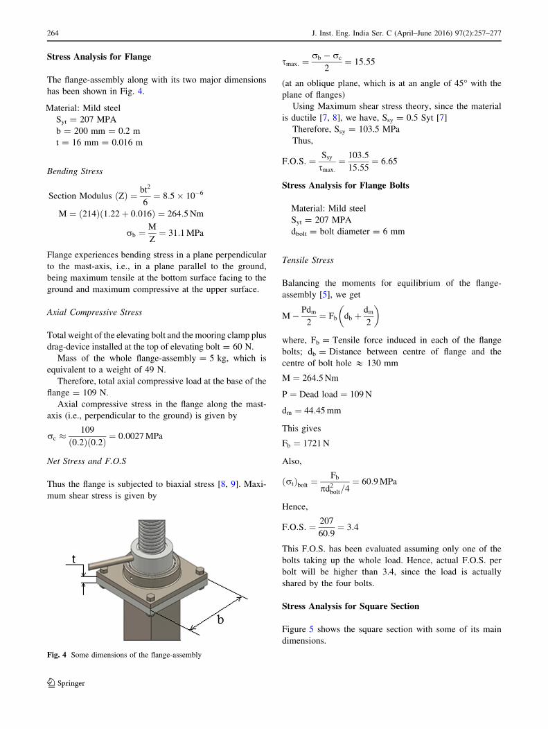
Stress Analysis for Flange
The flange-assembly along with its two major dimensions
has been shown in Fig. 4.
Material: Mild steel
Syt = 207 MPA
b = 200 mm = 0.2 m
t = 16 mm = 0.016 m
Bending Stress
Section Modulus Zð Þ ¼ bt2
6¼ 8:5� 10�6
M ¼ 214ð Þ 1:22þ 0:016ð Þ ¼ 264:5Nm
rb ¼M
Z¼ 31:1MPa
Flange experiences bending stress in a plane perpendicular
to the mast-axis, i.e., in a plane parallel to the ground,
being maximum tensile at the bottom surface facing to the
ground and maximum compressive at the upper surface.
Axial Compressive Stress
Total weight of the elevating bolt and the mooring clamp plus
drag-device installed at the top of elevating bolt = 60 N.
Mass of the whole flange-assembly = 5 kg, which is
equivalent to a weight of 49 N.
Therefore, total axial compressive load at the base of the
flange = 109 N.
Axial compressive stress in the flange along the mast-
axis (i.e., perpendicular to the ground) is given by
rc �109
0:2ð Þ 0:2ð Þ ¼ 0:0027MPa
Net Stress and F.O.S
Thus the flange is subjected to biaxial stress [8, 9]. Maxi-
mum shear stress is given by
smax: ¼rb � rc
2¼ 15:55
(at an oblique plane, which is at an angle of 45� with the
plane of flanges)
Using Maximum shear stress theory, since the material
is ductile [7, 8], we have, Ssy = 0.5 Syt [7]
Therefore, Ssy = 103.5 MPa
Thus,
F:O:S: ¼ Ssy
smax:¼ 103:5
15:55¼ 6:65
Stress Analysis for Flange Bolts
Material: Mild steel
Syt = 207 MPA
dbolt = bolt diameter = 6 mm
Tensile Stress
Balancing the moments for equilibrium of the flange-
assembly [5], we get
M� Pdm
2¼ Fb db þ
dm
2
where, Fb = Tensile force induced in each of the flange
bolts; db = Distance between centre of flange and the
centre of bolt hole & 130 mm
M ¼ 264:5Nm
P ¼ Dead load ¼ 109N
dm ¼ 44:45mm
This gives
Fb ¼ 1721N
Also,
ðrtÞbolt ¼Fb
pd2bolt=4¼ 60:9MPa
Hence,
F:O:S: ¼ 207
60:9¼ 3:4
This F.O.S. has been evaluated assuming only one of the
bolts taking up the whole load. Hence, actual F.O.S. per
bolt will be higher than 3.4, since the load is actually
shared by the four bolts.
Stress Analysis for Square Section
Figure 5 shows the square section with some of its main
dimensions.
Fig. 4 Some dimensions of the flange-assembly
264 J. Inst. Eng. India Ser. C (April–June 2016) 97(2):257–277
123

Grey Cast Iron was used, since it damps out the vibra-
tions caused by random turbulence of wind.
Tensile strength ¼ 276MPa
Side Bð Þ ¼ 76:2mm
Length lð Þ ¼ 1829mm
Thickness tð Þ ¼ 3mm
Bending Stress
M ¼ max: at the base of square� section
¼ 214ð Þ 1:22þ 0:016þ 1:829ð Þ ¼ 656Nm
I ¼ B4
12� B� 2tð Þ4
12¼ 7:86� 10�7
Maximum bending stress will be at the pair of opposite
outer vertices (max. tensile at one and max. compressive at
the other) of the square section at its base, when the drag
force on the airship is perpendicular to the diagonal of the
square section passing through the pair of other two
opposite vertices. Since the moored airship has yaw-
freedom of 360�, this situation can be easily encountered
with during field testing.
rb ¼ max: at y ¼ffiffiffi2
p76:2ð Þ2
mm ¼ 53:88mm
M
I¼ rb
y
This gives
rb ¼ 45MPa
Axial Compressive Stress due to weight
Designing the base of the square-section to support whole
of the mass of the mast, axial compressive load = 549 N.
Cross-sectional area of the section = 0.0008784 m2.
This gives axial compressive stress as
rc ¼ 0:625MPa
Net Stress and F.O.S
Thus we take normal stress (rn) as
rmax:ð Þtensile¼ 44:375MPa
rmax:ð Þcompressive¼ 45:625MPa
Since grey cast iron is a brittle material and its
compressive strength is much greater than the tensile
strength [10], the likely mode of failure is brittle fracture
due to tensile stress.
Therefore,
F:O:S: ¼ 276
44:375¼ 6:2
Stress Analysis for Adapter Base
The isometric view of the adapter assembly has been
shown in Fig. 6 with some of its dimensions.
Material: Mild Steel
Syt ¼ 250MPa ¼ Syc 7½ �D ¼ Outer diameter ¼ 200mm
d ¼ Inner diameter ¼ 120mm
Bending Stress
M � 214ð Þ 1:22þ 0:016þ 1:829ð Þ ¼ 656Nm
Now,
Section modulus Zð Þ ¼p D4 � d4� �
32D
This gives,
Z ¼ 6:8326� 10�4m4
Fig. 6 Dimensions of the adapter assembly
Fig. 5 Dimensions of the square section
J. Inst. Eng. India Ser. C (April–June 2016) 97(2):257–277 265
123

Thus,
rb ¼M
Z¼ 0:96MPa
Axial Compressive Stress Due to Weight
Designing the adapter-base to support whole of the mass of
the mast, axial compressive load = 549 N.
Cross-sectional area of the section = 0.02 m2.
This gives axial compressive stress as
rc ¼ 0:03MPa
Net Stress
Thus we take normal stress (rn) as
rmax:ð Þtensile¼ 0:93MPa
rmax:ð Þcompressive¼ 0:99MPa
Since the material used is ductile, yielding can be
considered as the likely mode of failure and hence can be
used as basis for designing. Since the compressive stress
produced here is far less than the Syc value [7], there are no
chances of yielding or crushing.
Stress Analysis for Adapter-Assembly Bolts
Material: Mild steel
Syt = 207 MPA
dbolt ¼ bolt diameter ¼ 10mm
Tensile Stress
Balancing the moments for equilibrium of the adapter-
assembly [5], we get
M� PB
2¼ Fb db þ
B
2
where, Fb = Tensile force induced in each of the bolts;
db = Distance between the adapter centre and the centre of
bolt hole = 180 mm; M = (214)(1.22 ? 0.016 ? 1.829)
= 656 Nm; P = Dead load = 549 N; B = 76.2 mm
This gives
Fb ¼ 2912N
Also,
ðrtÞbolt ¼Fb
pd2bolt=4¼ 37MPa
Hence,
F:O:S: ¼ 207
37¼ 5:6
This F.O.S. has been evaluated assuming only one of the
bolts taking up the whole load. Hence, actual F.O.S. per
bolt will be higher than 5.6, since the load is actually
shared by the 4 bolts.
Stress Analysis for Mast Legs
The cross-sectional dimensions of a mast-leg have been
shown in Fig. 7.
Material: Al-6351 aluminium alloy
Syt = 150 MPa = Syc and Fatigue strength = 90 MPa
Length of each leg = 1.8 m, and there are a total of five
legs.
Bending Stress
Total mass of the mast = 56 kg, which gives a weight of
549 N. Each of the five mast-legs support (1/5)th of the
total mast-weight. Hence, each leg should be strong enough
to safely bear that load. So, we take the mass supported by
each of the legs as ‘‘56/5 kg’’ (which is approx. equivalent
to a weight of 110 N) for design purpose.
The leg touches the ground only through the castor-
wheel attached to its end. The reaction force, exerted by the
ground on the castor-wheel tends to bend the leg.
Bending moment due to the weight of the mast is max.
at the hinged-end of the leg and is given by
Fig. 7 Dimensions of the cross-section of each of the mast-legs
266 J. Inst. Eng. India Ser. C (April–June 2016) 97(2):257–277
123

M1 ¼ 110ð Þ 1:8ð Þ ¼ 198Nm
Bending moment per leg due to air-drag on the moored
airship is given by
M2 ¼1
5214ð Þ 1:22þ 0:016þ 1:829ð Þ ¼ 131:2Nm
‘‘M2’’ will add up into ‘‘M1’’, when the drag force on the
airship is in a direction parallel and opposite to the mast-
leg, which is under consideration, hence gives the maxi-
mum possible bending moment for a leg, for a particular
orientation of the moored airship (which is having 360�yaw-freedom).
Therefore, maximum possible bending moment is given
by
M ¼ M1 þM2 ¼ 329:2Nm
Each leg is having hollow-rectangular cross-section with
the dimensions as shown above.
I ¼ 2:85� 10�7m4
rb ¼ max: at y ¼ 62
2mm ¼ 31mm
M
I¼ rb
y
This gives:
rb ¼ 35:8MPa
Bending stresses act along the longitudinal axis of the leg
itself.
Compressive Stress Along the Mast-Axis
The weight of the mast (acting at the pivot-joint of the leg
with the adapter-base) and the normal reaction (offered by
the ground through the castor-wheel) together induces the
compressive stress in the mast-leg in a direction parallel to
the vertical mast-axis, or we can say perpendicular to the
longitudinal axis of the leg itself.
Therefore, total compressive load per leg = (56)(9.8)/
5 & 110 N.
Maximum Compressive stress is given by
rc �110
Min:cross� sectional area
¼ 110
2 0:0025ð Þ 1:8ð Þ ¼ 0:012MPa
Net Stress and F.O.S
Thus the leg is subjected to biaxial stress [8, 9]. Maximum
shear stress is given by
smax: ¼rb � rc
2¼ 17:9MPa
(at an oblique plane, which is at an angle of 45� with the
axis of leg)
Since the material used is ductile, yielding can be con-
sidered as the likely mode of failure and hence can be used
as basis for designing.
Using Maximum shear stress theory, since the material
is ductile [7, 8], we have, Ssy ¼ 0:5Syt [7]
Therefore, Ssy ¼ 75MPa
Thus,
F:O:S: ¼ Ssy
smax:¼ 75
17:9¼ 4:2
Stress Analysis for Pitch Clamp (U-Clamp)
The isometric view of the set-up being used for providing
yaw and pitch freedoms to the moored airship has been
shown in Fig. 8 with its principal dimensions.
Material: Stainless Steel
Syt = 240 MPa
Ssy = 0.5 Syt = 120 MPa [7]
Tensile Stress
Under the estimated wind-load of 214 N, each arm of
‘‘U’’ takes half of this load, viz., 107 N. Maximum
tensile stress is in each of the two arms of U-clamp at
the location of bolt passing through it (where the
resisting cross-sectional area is minimum), and is given
by
rt ¼107
0:031ð Þ 0:005ð Þ � 0:012ð Þ 0:005ð Þ ¼ 1:13MPa
Therefore, considering yielding as the mode of failure,
F:O:S: ¼ 240
1:13¼ 212:4
Fig. 8 Dimensions of the yaw-setup and pitch clamp
J. Inst. Eng. India Ser. C (April–June 2016) 97(2):257–277 267
123
Shear Stress
Wind-load on the airship tends to induce double-shear in
each of the two arms of U-clamp beyond the location of
bolt passing through it.
s ¼ 107
2 0:0185ð Þ 0:005ð Þ ¼ 0:6MPa
Therefore, considering yielding as the mode of failure,
F:O:S: ¼ 120
0:6¼ 200
Stress Analysis for Bolts of Yaw and Pitch Setup
Material: Mild steel
Syt = 207 MPa
Ssy = 103.5 MPa [7]
Shear Stress
Wind-load on the airship tends to induce double-shear in
each of the two bolts passing across an arm of U-clamp
[not taking into account the shearing action over the bolt
due to the yaw-setup cup at the top of elevating bolt, we are
on more safe side, since triple or quarter shear (due to
additionally double or single shearing action by the wall of
the cup, depending upon whether the end of the bolt is
passed across the inner surface of the cup-wall or not)
offers even more resistance to the shearing action].
Shear stress in the bolt is given by
s ¼ 107
2p 0:012ð Þ2
4
h i ¼ 0:47MPa
Therefore, considering yielding as the mode of failure,
F:O:S: ¼ 103:5
0:47¼ 220
Design Requirements for Mooring Mast for IndoorAirships
The design requirements for the mooring mast for remotely
controlled indoor airships were arrived based on the user-
specified requirements, which have been summarised as
• The gross weight of the mast should be less than 10 kg.
• It should allow easy assembly and de-assembly within
10 min by two persons.
• It should be easily movable on the ground, and should
have height adjustable from 0.8 to 1.4 m. Also, its legs
should be foldable.
• The various components of the mast should also fit in a
standard suitcase (0.68 m 9 0.49 m 9 0.28 m).
• It should also allow the airship to move freely; 360� inyaw and roll, and -90� to ?30� in pitch in the moored
position. Further, it should be very easy to operate,
adjust, fold and unfold it.
Fabricated Design of the Mooring Mast for IndoorAirships
Keeping in mind the key design-requirements given above,
a mooring mast for indoor airships was designed and fab-
ricated as shown in the Fig. 9.
Conceptual Design for the Mast for IndoorAirships
The mooring mast for remotely controlled indoor airships
consists of an elevating bolt operated telescopic module
made of standard aluminium 6351, mounted on a tripod
adapter base which consists of standard aluminium (6351)
legs (which are locked in the right position by inclined Al-
strips) and lockable castor wheels, for ease in mobility. The
mast can accommodate non-rigid indoor airships of length
up to 5 meter. The various modules and components of the
mast were designed to enable quick assembly and trans-
portation. The mast has a specially designed mooring-clamp
at the top. The mast-structure is composed of mainly three
sub-assemblies, as described in the sections that follow.
Adapter Assembly
This assembly consists of the robust mast-base with three
U-clamps. The three legs of the mast are hinged into these
U-clamps (one in each) and are locked by the inclined
Aluminium (Al)-strips (using bolts). The Al-strips are
hinged into separate U-clamps attached on a block moun-
ted on the lower telescopic module using allen-bolts.
Telescopic Modules’ Assembly
There are two modules providing the desired height-
adjustability to the mast. The upper one, hereby referred
to as Hollow Square Section (HSS)-2, is moved in-or-
out of the lower one, which is referred to as Hollow
Square Section (HSS)-1, to adjust the mast’s height just
by rotating a pulley. This sub-system employs a bevel-
gear assembly which transfers the rotary-motion from
pulley to an elevating bolt supported in a bearing. This
causes a nut (fitted into the base of upper telescopic
module) to move up or down depending upon the sense
of rotation.
268 J. Inst. Eng. India Ser. C (April–June 2016) 97(2):257–277
123

Mooring Clamp Assembly
It consists of a hollow bent Al-rod (bent by 90�), with its
lower end fitted into a bearing at the top of upper tele-
scopic module for providing yaw-freedom (360�) and
other end carrying a mooring arrangement. The mooring
arrangement consists of a U-clamp, where a solid rod
passing across the two arms of ‘‘U’’ (each arm containing
a ball- bearing) provides pitch-freedom to the airship. A
properly designed stopper attached to the end of each of
the two arms of ‘‘U’’ clamp limits the pitch-freedom up to
?30�. A protruding solid rod is supported in two bearings
contained in a hollow-rod attached to the cross-rod
passing across the two arms of ‘‘U’’ clamp, and this rod
provides the required rolling-freedom (360�) to the
moored airship. This rod is having two thorough holes in
it, exactly matching with the holes in a frontal protruding
hollow rod at airship-nose. Then, the airship can be
moored with the mast just by putting the protruding solid-
rod of the mast into the hollow rod protruding from the
nose of the airship and simply putting the bolts-with-nuts
into the matching holes.
Figure 10 shows an indoor airship moored to this
mooring mast. The airship envelope is of Zhiyuan shape
[11], with length of 4.2 m and max. diameter of 1.27 m.
The design considerations for various subassemblies of
the mooring mast are listed in Table 2.
Stress Analysis for Mooring Mast for IndoorAirships
The volumetric drag coefficient CDV for an airship envel-
ope with L/D = 4 is estimated to be 0.0255, using the
empirical formula suggested by Hoerner [4]. Though the
forward velocity of indoor airship is quite small, but it
could face higher winds while being relocated. Hence, the
mooring mast was designed to bear a wind load of 25 m/s.
q ¼ 1:225kg=m3
V ¼ 3:6m3
As is clear from the airships flight-tested in the past, the
drag force on the bare hull is approximately 50 % of the
drag force on the airship as a whole [6], hence, the drag
force on the airship is given by
FD ¼ 2ðFDEÞ ¼ 2ð Þ 12qV2=3v2CDV � 47N
Mass of the overhanging end-portion of the mooring clamp
is 0.8 kg, hence Bending Moment (MW) at any transverse
Fig. 9 CAD model (left) and photograph (right) of the fully assembled mooring mast for indoor airships
J. Inst. Eng. India Ser. C (April–June 2016) 97(2):257–277 269
123

cross-section due to its weight (about the centroidal axis of
any transverse section, say mast base, or hollow square
section) = (0.8)(9.8)(0.13) i.e., MW = 1 Nm. It is assumed
that the weight acts at approximately 0.13 m horizontal
distance from the vertical axis passing through the centroids
of the respective transverse sections of the mast.
Stress Analysis for Elevating Bolt
Material: Mild Steel [MS-2062 (MS-Bright)]
Syt = 250 MPa
Major diameter (d) = 20 mm
Thread pitch (p) = 3.8 mm
Pitch diameter (dp) = 17.5 mm
Minor diameter (dm) = 15 mm
Length of threaded portion (lb) = 609.6 mm
Length and diameter of the shank of the elevating bolt
below the threaded portion (through which the elevating
bolt is supported in a bearing placed just above the mast-
base) = 46 mm and 15 mm respectively.
Lead angle [5] is given by
tan k ¼ p
pdp
tan k ¼ 3:8
3:14ð Þ 17:5ð Þk ¼ 3:95�
Lifting force required [5] is given by
P1 ¼Fðsin kþ lcoskÞcos k� l sin k
Coefficient of friction lð Þ ¼ 0:2
Force Fð Þ ¼ 3:6ð Þ 9:8ð Þ ¼ 35:3N
P1 ¼35:3½sin 3:95�ð Þ þ 0:2cos 3:95�ð Þ�
cos 3:95�ð Þ � 0:2 sin 3:95�ð ÞP1 ¼ 9:6N
Lowering force required [5] is given by
P2 ¼Fðl cos k� sin kÞcos kþ l sin k
P2 ¼35:3½0:2 cos 3:95�ð Þ � sin 3:95�ð Þ�
cos 3:95�ð Þ þ 0:2 sin 3:95�ð ÞP2 ¼ 4:5N
Torque required for lifting
T1 ¼ðP1Þ dp
� �
2
T1 ¼9:6ð Þ 17:5� 10�3ð Þ
2
T1 ¼ 0:084Nm
Torque required for lowering
Fig. 10 Photograph of an
indoor airship moored on the
fabricated Mast
270 J. Inst. Eng. India Ser. C (April–June 2016) 97(2):257–277
123

Table 2 Design considerations for various sub-assemblies
Sub-assembly CAD model Stresses checked Type of failure Material
Elevating Bolt and Nut Bending Bolt rupture Mild steel
Shear Ductile failure
Bearing Abrasive wear
Axial Impact fatigue
Adapter assembly Bending Ductile failure Al-6351 alloy
Axial
Telescopic Modules’ assembly Bending Rupture Al-6351 alloy
Compressive Ductile failure
Mooring clamp Impact Rupture Al-6351 alloy
Tensile Impact fatigue
Bending
J. Inst. Eng. India Ser. C (April–June 2016) 97(2):257–277 271
123

T2 ¼ðP2Þ dp
� �
2¼ 4:5ð Þ 17:5� 10�3ð Þ
2
T2 ¼ 0:04Nm
Shank diameter of the elevating bolt may be used for the
design purpose without taking into account the effect of
stress-concentration [7].
Bending Stress
M ¼ max: at the bottom most section of elevating bolt
¼ Bending Moment due to drag
force on the airshipþMW
¼ 47 0:12þ 0:5þ 0:7ð Þ þ 1
¼ 63:04 Nm
I ¼ p64
0:015ð Þ4h i
¼ 2:48� 10�9m4
rb ¼ max: at y ¼ 15
2mm ¼ 7:5mm
M
I¼ rb
y
This gives:
rb ¼ 190MPa
Axial Compressive Stress
Total mass exerting the axial load (due to weight) at the
bottom most section of elevating bolt (taking into account
the masses of mooring clamp, HSS-2, nut, bevel-gears,
elevating bolt itself, etc.) = 3.6 kg. Hence, total axial
load = (3.6)(9.8) = 35.3 N.
Area of cross-section of shank of elevating
bolt = 0.00017 m2.
Therefore, axial compressive stress at the bottom of the
elevating bolt due to the weight is calculated as
rC ¼ 0:2MPa
Thus, the axial compressive stress due to the weight is
negligible as compared to the axial stress due to bending,
hence can be neglected in comparison with the latter.
Thus we take normal stress (rn) as
rmax:ð Þtensile¼ 190MPa
rmax:ð Þcompressive¼ 190MPa
Torsional Shear Stress
Maximum Shear Stress in the screw body (at the shank
surface) is given by
s ¼ 16T1
pd3m¼ 16 0:084ð Þ
p 15� 10�3ð Þ3
s ¼ 0:13MPa
Net Stress and F.O.S
Thus, the elevating bolt is subjected to a combination of
bending and torsional moments. The principal stress and
principal shear stress can be calculated by constructing
Mohr’s circle [7]. Since the elevating bolt has been
made of Mild steel, which is a ductile material, hence
‘‘maximum shear stress’’ theory is applicable for its
design [7, 8].
Principal shear stress [7] is calculated as
smax: ¼
ffiffiffiffiffiffiffiffiffiffiffiffiffiffiffiffiffiffiffiffiffiffiffiffiffiffiffirn
2
� �2
þ s2� �s
¼
ffiffiffiffiffiffiffiffiffiffiffiffiffiffiffiffiffiffiffiffiffiffiffiffiffiffiffiffiffiffiffiffiffiffiffiffiffiffiffiffiffi190
2
2
þ 0:13ð Þ2" #vuut
smax: ¼ 95MPa
Since the material used is ductile, yielding can be consid-
ered as the likely mode of failure and hence can be used as
basis for designing.
According to maximum shear stress theory, Ssy = 0.5
Syt [7]. Therefore, Ssy = 125 MPa
Thus,
F:O:S: ¼ Ssy
smax:¼ 125
95¼ 1:3
Stress Analysis for Mast-Base
Material: Al-6351 aluminium alloy
Syt ¼ 150MPa ¼ Syc 7½ � and Fatigue strength ¼ 90MPa
The cross-sectional and longitudinal dimensions of the
mast-base have been shown in Fig. 11.
Fig. 11 Dimensions of the Mast-base
272 J. Inst. Eng. India Ser. C (April–June 2016) 97(2):257–277
123

Bending Stress
M ¼ max: at the bottom of Mast� base
¼ Bending Moment due to drag
force on the airshipþMW
¼ 47 0:12þ 0:5þ 0:7þ 0:03ð Þ þ 1
¼ 63:45 Nm
I ¼ p64
0:09ð Þ4� 0:03ð Þ4h i
¼ 3:18� 10�6m4
rb ¼ max: at y ¼ 90
2mm ¼ 45mm
M
I¼ rb
y
This gives:
rb ¼ 0:912MPa
Axial Compressive Stress
For the structural arrangement of the mast, whole of the
mast-weight can be supposed to be balanced by the mast-
base. Further, assuming this load at the mast base and
designing HSS-1 accordingly, we are on more safe side.
Thus, taking axial compressive load = (9.055)(9.8) =
88.7 N and area of cross-section of the mast-base =
0.005652 m2
Axial compressive stress at the bottom of the HSS-2 due
to the weight is calculated as
rC ¼ 0:016MPa
Net Stress and F.O.S
Therefore,
rmax:ð Þtensile¼ 0:896MPa
rmax:ð Þcompressive¼ 0:928MPa
Since the material used is ductile, yielding can be
considered as the likely mode of failure and hence can be
used as basis for designing.
Thus,
F:O:S: ¼ 150
0:928¼ 161:6
Stress Analysis for Mast-Legs
Material: Al-6351 aluminium alloy
Syt = 150 MPa = Syc [7] and Fatigue strength = 90
MPa
Length of each leg = 0.434 m, and there are a total of
three legs.
Bending Stress
Total mass of the mast = 9.055 kg, which gives a weight of
‘‘88.7 N’’. Each of the three mast-legs support (1/3)rd of the
total mast-weight. Hence, each leg should be strong enough
to safely bear that load. So, we take the mass supported by
each of the legs as ‘‘9.055/3 kg’’ (which is approx. equivalent
to a weight of 29.6 N) for design purpose.
The leg touches the ground only through the castor-
wheel attached to its end. The reaction force, exerted by the
ground on the castor-wheel tends to bend the leg.
Bending moment due to the weight of the mast is max.
at the hinged-end of the leg and is given by
M1 ¼ ð29:6Þð0:434Þ ¼ 12:8Nm
Bending moment per leg due to air-drag on the moored
airship is given by
M2 ¼1
3ð47Þð0:12þ 0:5þ 0:7þ 0:03Þ ¼ 21:15Nm
‘‘M2’’ will add up into ‘‘M1’’, when the drag force on the
airship is in a direction parallel and opposite to the mast-
leg, which is under consideration, hence gives the maxi-
mum possible bending moment for a leg, for a particular
orientation of the moored airship (which is having 360�yaw-freedom).
Therefore, maximum possible bending moment is given
by
M ¼ M1 þM2 ¼ 33:95Nm
Each leg is a hollow-cylinder with internal diameter of
‘‘0.028 m’’ and outer diameter of ‘‘0.032 m’’.
Hence, for bending consideration,
I ¼ p64
0:032ð Þ4� 0:028ð Þ4h i
¼ 2:13� 10�8m4
rb ¼ max:at y ¼ 32
2mm ¼ 16mm
M
I¼ rb
y
This gives
rb ¼ 25:5MPa
Bending stresses act along the longitudinal axis of the
leg itself.
Compressive Stress Along the Mast-Axis
The weight of the mast (acting at the pivot-joint of the leg
with the adapter-base) and the normal reaction (offered by
the ground through the castor-wheel) together induces the
compressive stress in the mast-leg in a direction parallel to
J. Inst. Eng. India Ser. C (April–June 2016) 97(2):257–277 273
123

the vertical mast-axis, or we can say perpendicular to the
longitudinal axis of the leg itself.
Therefore, total compressive load per leg = (9.055)(9.8)/
3 & 29.6 N
Maximum compressive stress is given by
rc �29:6
Min:cross� sectional area
¼ 29:6
2 0:002ð Þ 0:434ð Þ ¼ 0:017MPa
Net Stress and F.O.S
Thus the leg is subjected to biaxial stress [8, 9]. Maximum
shear stress is given by
smax: ¼rb � rc
2¼ 12:7MPa
(at an oblique plane, which is at an angle of 45� with the
axis of leg).
Since the material used is ductile, yielding can be con-
sidered as the likely mode of failure and hence can be used
as basis for designing.
Using Maximum shear stress theory, since the material
is ductile [7, 8], we have, Ssy = 0.5 Syt [7].
Therefore, Ssy = 75 MPa
Thus,
F:O:S: ¼ Ssy
smax:¼ 75
12:7¼ 5:9
Stress Analysis for the Bolts at hinges
Material: Mild Steel
Syt = 207 MPa
Shear Stress
Each of the bolts used for hinging of a mast-leg can be
designed to be strong enough to safely bear the weight of
the mast as a whole. So, we take the mass supported by
each of the bolts as ‘‘9.055 kg’’ for design purpose, which
is equivalent to a load of 88.7 N.
Each of those bolts used is of 6 mm dia. (and 2 inch
length).
Each bolt is subjected to double-shear under the com-
bined action of weight of the mast and the reaction from
the ground.
Shear stress in the bolt is given by
s ¼ 88:7
2p 0:006ð Þ2
4
h i
s ¼ 1:6MPa
Since the material used is ductile, yielding can be
considered as the likely mode of failure and hence can be
used as basis for designing.
According to maximum shear stress theory, Ssy = 0.5
Syt [7]
Therefore, Ssy = 103.5 MPa
Thus,
F:O:S: ¼ Ssy
s¼ 103:5
1:6¼ 64:7
Stress Analysis for HSS-1 and HSS-2 (portions
of Telescopic Modules’ Assembly)
Now the Airship moored to the mast has 360� Yaw-
freedom. Thus the airship can rotate freely about the
(vertical) axis of the mast. Due to the air-gusts, the
airship will be at different positions around the mast at
different instants of time (due to yaw-freedom). But at
whatever position it is at an instant of time, the air-flow
through around the airship will exert the air-drag. This
force will act on the airship along the (horizontal) axis
of the airship. (Note that in the moored position, our
airship was exactly horizontal due to perfect balancing
of the forces along vertical and the mast was not con-
tributing at all towards its (airship’s) vertical
equilibrium).
Therefore, the drag force is acting parallel to the ground.
The airship exerts this force on the mooring mast directed
parallel to the ground. As airship will rotate around the
mast under the effects of air-gusts, the drag force will also
keep on rotating around the mast as shown in Fig. 12. Now
as the mast stands straight on the ground, this force will try
Fig. 12 Rotation of the drag force on the airship and hence the
bending-axis for hollow square sections due to yaw-freedom of the
moored airship
274 J. Inst. Eng. India Ser. C (April–June 2016) 97(2):257–277
123

to bend the HSS-1 and HSS-2 about the axis parallel to the
ground and perpendicular to the instantaneous direction of
the drag force. Thus the axis of bending of the HSS-1 and
HSS-2 will keep on changing continuously with the
changing orientation of the drag force.
The bending stresses will be maximum at the outer
vertex of the hollow square cross-section of HSS-1 or HSS-
2 when the drag force is perpendicular to the diagonal of
the square cross-section, as shown in Fig. 12a or e, since,
in this case, ‘‘y’’ is maximum.
Bending Stress = Maximum tensile at the vertex oppo-
site to the vertex at which the force acts
Bending Stress = Maximum compressive at the vertex
at which the force acts
The cross-sectional dimensions of the hollow square
sections (HSS-1 and HSS-2) have been indicated in
Fig. 13.
For Hollow Square Section-2 (HSS-2),
Material: Al-6351 aluminium alloy
Syt = 150 MPa = Syc [7] and Fatigue strength =
90 MPa
Bending Stress
M ¼ max: at the base of HSS - 2
¼ Bending Moment due to drag
force on the airshipþMW
¼ 47 0:12þ 0:5ð Þ þ 1
¼ 30:14Nm
I ¼ 1
120:0508ð Þ4� 0:0458ð Þ4
h i¼ 1:88� 10�7m4
rb ¼ max: at y ¼ffiffiffi2
p50:8ð Þ2
mm ¼ 35:9mm
M
I¼ rb
y
This gives:
rb ¼ 5:75MPa
Axial Compressive Stress
Mass of HSS-2 = 0.665 kg
Mass of mooring clamp = 0.955 kg
Mass of nut = 0.150 kg
Hence, total axial load = (1.77)(9.8) = 17.3 N
Area of cross-section of HSS-2 = 0.000483 m2
Therefore, axial compressive stress at the bottom of the
HSS-2 due to the weight is calculated as
rC ¼ 0:036MPa.
Net Stress and F.O.S
Therefore
rmax:ð Þtensile¼ 5:7MPa
rmax:ð Þcompressive¼ 5:8MPa
Since the material used is ductile, yielding can be
considered as the likely mode of failure and hence can be
used as basis for designing.
Thus,
F:O:S: ¼ 150
5:8¼ 25:8
For Hollow Square Section-1 (HSS-1),
Material: Al-6351 aluminium alloy
Syt = 150 MPa = Syc [7] and Fatigue strength =
90 MPa
Bending Stress
M ¼ max: at the base of HSS-1
¼ Bending Moment due to drag
force on the airshipþMW
¼ 47 0:12þ 0:5þ 0:7ð Þ þ 1
¼ 63:04 Nm
I ¼ 1
120:0635ð Þ4� 0:0585ð Þ4
h i¼ 3:789� 10�7m4
rb ¼ max: at y ¼ffiffiffi2
p63:5ð Þ2
mm ¼ 44:9mm
M
I¼ rb
y
This gives:
rb ¼ 7:47MPa
Axial Compressive Stress
Due to inclined aluminium-strips joining HSS-1 with the
legs and support to whole mast through the mast-base
Fig. 13 Dimensions of HSS-1 and HSS-2
J. Inst. Eng. India Ser. C (April–June 2016) 97(2):257–277 275
123

joined with the legs, whole of the mast-weight can be
supposed to be balanced by the base of HSS-1. Further,
assuming this load at the mast base and designing HSS-1
accordingly, we are on more safe side.
Thus, taking axial compressive load = (9.055)(9.8) =
88.7 N and area of cross-section of HSS-1 = 0.00061 m2
Axial compressive stress at the bottom of the HSS-2 due
to the weight is calculated as
rC ¼ 0:145MPa
Net Stress and F.O.S
Therefore
rmax:ð Þtensile¼ 7:325MPa
rmax:ð Þcompressive¼ 7:615MPa
Since the material used is ductile, yielding can be
considered as the likely mode of failure and hence can be
used as basis for designing.
Thus,
F:O:S: ¼ 150
7:615¼ 19:7
Stress Analysis for Bent Rod (a part of Mooring
Clamp)
Material: Al-6351 aluminium alloy
Syt ¼ 150MPa ¼ Syc 7½ � and Fatigue strength ¼ 90MPa
Bending Stresses
M ¼ maximum at the base of the bent rod ð90�Þ¼ BendingMoment due to drag
force on the airshipþMW
¼ 47 0:12ð Þ þ 1
¼ 6:64Nm
I ¼ p 0:02ð Þ4
64¼ 7:85� 10�9m4
M
I¼ rb
y
rb ¼6:64
7:85� 10�9� 10� 10�3� �
¼ 8:46MPa
Axial Compressive Stress
Mass of the mooring clamp as a whole = 0.955 kg.
There, axial compressive stress at the bottom of the bent-
rod due to the weight of the mooring-clamp is given by
rC ¼ 0:955� 9:81
p 0:02ð Þ2=4¼ 0:03MPa
Net Stress and F.O.S
Therefore,
rmax:ð Þtensile¼ 8:43MPa
rmax:ð Þcompressive¼ 8:49MPa
Since the material used is ductile, yielding can be
considered as the likely mode of failure and hence can be
used as basis for designing.
Thus,
F:O:S: ¼ 150
8:49¼ 17:6
Stress Analysis for Protruding Solid Mooring Rod
Material: Al-6351 aluminium alloy
Syt = 150 MPa and Fatigue strength = 90 MPa
Tensile Stress
Diameter of this rod = 8 mm
rt ¼47
p 0:008ð Þ2=4¼ 0:94MPa
Since the material used is ductile, yielding can be
considered as the likely mode of failure and hence can be
used as basis for designing.
Thus,
F:O:S: ¼ 150
0:94¼ 159:5
Conclusions and Suggestions for Improvement
Regarding the mooring mast for outdoor airships, the total
weight of the whole system was around 56 kg, which is
within the upper limit of 60 kg with a 15 % margin for
growth. During several trials, it was seen that the mast
could easily be assembled in less than 20 min by a two-
member team, as desired. The use of power screw operated
telescopic module ensures that the alteration of the height
requirement for the mast is met easily, without the need to
remove and tighten any bolts. Desired pitch and yaw
freedom is available through the gimbal mechanism. The
five legged base with adapter assembly make the mast
stable. Thus, it can be concluded that this modified mast
designed for ground handling of remotely controlled out-
door airships met all the user specified requirements.
However, few improvements to this basic design can be
incorporated. First of all, the rotation of the elevating nut
can be made more convenient by replacing the nut handle
with a bevel gear assembly along with pulleys. In the
276 J. Inst. Eng. India Ser. C (April–June 2016) 97(2):257–277
123

adapter assembly, the mast legs can be provided with
spring activated quick response mechanism and all terrain
lockable wheel system, to enable quick folding and hence
reducing the effort and time required for de-assembly.
Regarding the mooring mast for indoor airships, the
total mass of the mast was found to be around 9.055 kg,
thus well within the required limits. It was very easy to
assemble and dis-assemble by 2 persons in 10 min. The
mooring-clamp provided the airship the required yawing-
freedom (360�), pitching-freedom (-90� to ?30�) and
rolling-freedom (360�). The telescopic-modules’ assembly
provided the mast the height adjustable from 0.8 to 1.5 m.
The tripod-base made the mast stable on ground and the
castor-wheels made it easily movable on the ground. The
inclined Al-strips allowed folding the mast-legs by
removing just three bolts. It was possible to pack all the
components of this mast in a standard suitcase, making it
highly portable. Thus, it can be concluded that this mast
successfully met all the user specified requirements.
But, still some improvements are possible in its struc-
tural design. The legs can be made very-easily foldable and
lockable by using a spring-activated bolt besides a fixed
bolt used for hinging of each leg into a U-clamp of the
adapter assembly.
It is to be noted that some of the factors of safety as
calculated above are quite high. At first look it may appear
that the dimensions of various components could be
reduced to bring down these numbers. But that will reduce
the efficacy of the mast, for e.g., if the size of the mast-base
is reduced, it might become unstable. Also, it is very dif-
ficult to predict the magnitude and direction of the ambient
wind that the mast will have to face while deployed in the
field. Hence, the mast may have to face much larger forces
than what are expected. Further, the mast may also expe-
rience impact-loads due to sudden gusts of the air. Thus,
the mast components, in reality, may be subjected to far
greater impact and/or dynamic loads. Further, the effects of
stress-concentration have also not been taken into account.
Keeping these uncertainties in mind, incorporation of high
factors of safety can be justified.
Acknowledgments The authors are highly thankful to the students,
researchers and interns of the Lighter-Than-Air Systems Laboratory
of Aerospace Engineering Department of IIT Bombay where this
work was carried out. We are also thankful to the fellow students at
Department of Mechanical Engineering, DCRUST Murthal, who
helped indispensably in the brain-storming technical discussions, and
also in preparation and uploading of the manuscript. Further, we are
highly grateful to IRCC, IIT Bombay and KVPY (which is being
administered by IISc Bangalore and funded by DST, Govt. of India)
for financially assisting two of the co-authors for the project-work
carried out at LTA Systems Lab, IIT Bombay, and the last, but not the
least, we are also highly thankful to Mr. Nilesh Dhanve, LTA Systems
Lab, Department of Aerospace Engineering, IIT Bombay for helping
indispensably in completing all the official formalities and arranging
the funds for the project.
References
1. D. Howe, Mooring, in Airship Technology, 2nd edn., Cambridge
Aerospace Series: 10, ed. by G.A. Khoury (Cambridge University
Press, London, 2012), pp. 258–277
2. S.M. Kale, R.S. Pant, Structural design of mooring mast for a
remotely controlled airship, in Proceedings of the 5th Interna-
tional Convention of The Airship Association, 2004, Oxford,
England
3. A. Goyal, D. Pandey, R.S. Pant, Design of a portable mooring
mast with drag force measuring device for remotely controlled
airships, AIAA-2011-6833, in Proceedings of AIAA’s 19th
Lighter-Than-Air (LTA) Technology Conference, 20–22 Sep
2011, Virginia Beach, Norfolk, Virginia
4. S.F. Hoerner, Fluid Dynamic Drag (Dr.-Ing. S.F. Hoerner, Mid-
land Park, N.J., 1957), pp. 11.1–11.4
5. R.L. Norton, Design of Machinery, 3rd edn. (Tata McGraw Hill,
New Delhi, 2005)
6. G.A. Khoury, Airship Technology, 2nd edn. (Cambridge
University Press, Cambridge, 2012), pp. 25–34. ISBN 978-1-107-
01970-6
7. V.B. Bhandari, Design of Machine Elements, 8th reprint of 3rd
edn. (Tata McGraw Hill Education Private Limited, New Delhi,
2012) ISBN-13: 978-0-07-068179-8
8. G.H. Ryder, Strength of Materials, reprint of 3rd edn with SI
units (1969) (Macmillan Publishers India Limited, Chennai,
2009) ISBN-13: 978 0333-93536-1
9. D.S. Kumar, Elements of Mechanical Engineering, 2nd edn. (S.K.
Kataria & Sons, New Delhi, 2008), pp. 467–469
10. R. Singh, Introduction to Basic Manufacturing Processes and
Workshop Technology, 2nd edn. (New Age International Pub-
lishers, New Delhi, 2010), pp. 69–70. ISBN 978-81-224-3070-7
11. P. Liu, G. Fu, L. Zhu, X. Wang, Aerodynamic Characteristics of
Airship Zhiyuan-1. J. Shanghai Jiaotong Univ. (Sci.) 18(6),679–687 (2013)
J. Inst. Eng. India Ser. C (April–June 2016) 97(2):257–277 277
123