Embed Size (px)
Citation preview
26TH INTERNATIONAL CONGRESS OF THE AERONAUTICAL SCIENCES
1
Abstract
The objective of this paper is to demonstrate the deployment of Design for Process Excellence at Rolls-Royce, which led to a step-change improvement in cost, time, and nonconformance during new product development. Rolls-Royce engineering was challenged with the tasks of supporting an increasing work load and sustaining technological competitiveness while driving process improvements to gain engineering productivity improvements. Rolls-Royce chose to identify new methods to increase robustness and automation, while incorporating and then enhancing industry best practices. By utilizing Design for Process Excellence, Rolls-Royce was able to bring robustness into design by understanding and accounting for variability during the early stages of the design process. The goal was to design products, using Design for Process Excellence, to enter service earlier with reduced and quantified risks and with increased predictability and product performance.
The Rolls-Royce Design for Process Excellence utilizes the Define, Characterize, Optimize, and Verify model, with cross-functional teamwork being the key to producing results. Many different classical lean design tools are utilized during the process to help realize a product that consistently achieves customer expectations. A specific example is the design of recent engine development within our civil market, which this paper chronicles for specific implementation successes and pitfalls.
1 Introduction The deployment of new processes within an organization can be challenging, but if executed properly can result in step-change improvements in those metrics driving customer satisfaction and good business. As with many companies, engineering at Rolls-Royce is challenged with supporting increasing workloads while seeking creativity to sustain technological advantage. By continually building upon and incorporating industry best practice, Rolls-Royce has embraced Process Excellence to bring robustness into design by understanding and accounting for variation during the early stages of the design process.
The Rolls-Royce model uses various Six Sigma tools, along with standard design processes, and packages these tools under the acronym DCOV (Define, Characterize, Optimize, Verify). This new method of designing components requires a methodical approach beginning with understanding customer requirements and design space through to verifying the assumptions made throughout the process with analysis and hardware testing.
After implementing pilot projects on a number of programs, Rolls-Royce has applied Process Excellence in a highly disciplined manner on a new centerline engine being designed for a performance oriented commercial aircraft. The new engine’s requirements include significant noise, weight, cost, specific fuel consumption (SFC), schedule, and vibration challenges. Ultimately, the Process Excellence objective is to reduce weight and cost in various
DESIGN FOR PROCESS EXCELLENCE—ENSURING TIMELY AND COST-EFFECTIVE SOLUTIONS
Norm Egbert*, Paul McCoy**, Doug Schwerin†, Jarrett Jones††, Alexander Karl††
*Rolls-Royce, **Rolls-Royce Corporation – Engineering, †Rolls-Royce – Transmissions and Structures, ††Rolls-Royce North America
Keywords: DCOV, Robust Design, Design for Six Sigma, Design Space, Cost-Effective

NORM EGBERT, PAUL MCCOY, DOUG SCHWERIN, JARRETT JONES, ALEXANDER KARL
2
components while maintaining the previously noted requirements.
2 Nomenclature AHP Analytic Hierarchy Process
CDOV Concept, Design, Optimize, and Verify
Cp Process Capability
Cpk Process Capability Index
CTQ Critical to Quality
DCOV Define, Characterize, Optimize, and Verify (a Design for Six Sigma approach used by Rolls-Royce)
DFMEA Design Failure Mode and Effects Analysis
DfPE Design for Process Excellence (a Rolls-Royce methodology utilizing Design for Six Sigma processes)
DfSS Design for Six Sigma
DMADV Define, Measure, Analyze, Design, Verify
DMEDI Define, Measure, Explore, Develop, Implement
DOE Design of Experiments
FMA Function Means Analysis
IDOV Identify, Design, Optimize, Verify
Process Uses the Six Sigma DMAIC Excellence methodology but gives added
emphasis to customer focus, process compliance and continuous improvement using a range of appropriate tools.
QFD Quality Function Deployment
Robust Design A Rolls-Royce methodology utilizing design for variation processes
SFC Specific Fuel Consumption
VOC Voice of the Customer
3 Overview of the DCOV Process The foundation of Design for Six Sigma (DfSS) is the same throughout the industry; however, the roadmap to get to the finished product is very often defined differently. Use of the Define, Characterize, Optimize, and Verify (DCOV) methodology to complete robust designs using a DfSS approach helps the engineering community focus on customer requirements, design space exploration, automa-tion/simulation, error proofing, and verification of the design via a test program. After comple-tion of each phase, a gate review is held with the sponsors and a master ‘black belt’ before proceeding on to the next phase of the process.
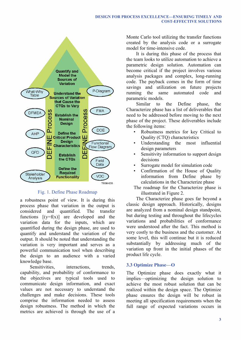
3.1 Define Phase—D The Define phase is the backbone of the process and consists of a choice of various, classic Six Sigma tools and a methodical process of steps that is dependent on the scope of the project the team is working through. The team must deliver the following items before proceeding to the next phase:
• Validated customer requirements • Validated concept • Nominal design • Parameter diagram • What-why table • Models for input variation
The roadmap for the Define phase is illustrated in Figure 1.
The Define phase is very similar to the Define, Measure, and Explore phases of the DMEDI process, the Identify & Design phases of the IDOV methodology, and the Define, Measure, Analyze, & Design phases of the DMADV process. Rolls-Royce takes a deeper dive into the technical aspects of the DfSS approach in an attempt to address as many potential design flaws before the product reaches the testing phase.
3.2 Characterize Phase—C The Characterize phase addresses the fundamental difference between the classic design approach and the DfSS approach. During this phase, the nominal design is assessed from
DESIGN FOR PROCESS EXCELLENCE—ENSURING TIMELY AND COST-EFFECTIVE SOLUTIONS
3
Fig. 1. Define Phase Roadmap
a robustness point of view. It is during this process phase that variation in the output is considered and quantified. The transfer functions [(y=f(x)] are developed and the variation data for the inputs, which are quantified during the design phase, are used to quantify and understand the variation of the output. It should be noted that understanding the variation is very important and serves as a powerful communication tool when describing the design to an audience with a varied knowledge base.
Sensitivities, interactions, trends, capability, and probability of conformance to the objectives are typical tools used to communicate design information, and exact values are not necessary to understand the challenges and make decisions. These tools comprise the information needed to assess design robustness. The method in which the metrics are achieved is through the use of a
Monte Carlo tool utilizing the transfer functions created by the analysis code or a surrogate model for time-intensive code.
It is during this phase of the process that the team looks to utilize automation to achieve a parametric design solution. Automation can become critical if the project involves various analysis packages and complex, long-running code. The payback comes in the form of time savings and utilization on future projects running the same automated code and parametric models.
Similar to the Define phase, the Characterize phase has a list of deliverables that need to be addressed before moving to the next phase of the project. These deliverables include the following items:
• Robustness metrics for key Critical to Quality (CTQ) characteristics
• Understanding the most influential design parameters
• Sensitivity information to support design decisions
• Surrogate model for simulation code • Confirmation of the House of Quality
information from Define phase by calculations in the Characterize phase
The roadmap for the Characterize phase is illustrated in Figure 2.
The Characterize phase goes far beyond a classic design approach. Historically, designs are analyzed from a nominal design standpoint, but during testing and throughout the lifecycles variations and probabilities of conformance were understood after the fact. This method is very costly to the business and the customer. At some level, this will continue but it is reduced substantially by addressing much of the variation up front in the initial phases of the product life cycle.
3.3 Optimize Phase—O
The Optimize phase does exactly what it implies—optimizing the design solution to achieve the most robust solution that can be realized within the design space. The Optimize phase ensures the design will be robust in meeting all specification requirements when the full range of expected variations occurs in

NORM EGBERT, PAUL MCCOY, DOUG SCHWERIN, JARRETT JONES, ALEXANDER KARL
4
Fig. 2. Characterize Phase Roadmap
component requirements and tolerances (refer to Figure 3). The Optimize phase also ensures the tolerances chosen are within capability limits of the supply base and manufacturing facilities. Optimization includes not only the performance objectives, but as many of the objectives as possible, which ultimately drives product costs and in-service costs. Optimizing a design solution for many CTQs rather than just the performance objectives is a step change in the product development cycle and will ultimately drive in-service costs lower. This becomes essential when the product needs to stay on wing as long as possible to meet customer expectations and business demands.
The Optimize phase deliverables include the following items:
• Solution that is robust against part variation and implied (and non-implied) customer requirements
Fig. 3. Design Space Versus Design Iteration
• Tolerance settings that simultaneously satisfy robustness and the capability of manufacturing and supply chain
• Models that can be reused in similar designs
• Model established for the preliminary design process
The roadmap for the Optimize phase is illustrated in Figure 4.

DESIGN FOR PROCESS EXCELLENCE—ENSURING TIMELY AND COST-EFFECTIVE SOLUTIONS
5
Fig. 4. Optimize Phase Roadmap
3.4 Verify Phase—V The final phase of the DCOV process is the Verify phase. This phase is not utilized as often as the prior phases due to the cost of testing in comparison to the cost of analysis. One design may go through the Define, Characterize, and Optimize phases numerous times before finally being tested. This is related to the fidelity of the analytical methods and the costs of hardware testing compared to analysis capability costs. The analysis available today is more powerful, is less time intensive, and is improved in fidelity compared to analyses available in the past. Our dependence on empiricism is reduced, so we can now take advantage of computer enabled analytics to create accurate simulations in an effort to reduce hardware tests. However, hardware testing remains critical for certain high complexity situations, but the levels of hardware testing currently needed are reduced when compared to levels required in the past.
The Verify phase seeks to put together a logical and more focused testing plan based upon information previously gathered to confirm the assumptions, analysis, and conclusions created in the first three phases. As with all Six Sigma approaches, the Verify phase also creates a control plan for production once the product is released. Verification can be one of the most overlooked steps of any Six Sigma project but it ultimately becomes the most important to sustaining a robust design.
The Verify phase deliverables are identified in the following list:
• Confirmation of assumptions from prior phases of the process
• Measured data statistically within predicted values
• In-service data gathering and exploitation strategy
• Report and lessons learned documented for the next projects.
The roadmap for the Verify phase is illustrated in Figure 5.
Fig. 5. Verify Phase Roadmap

NORM EGBERT, PAUL MCCOY, DOUG SCHWERIN, JARRETT JONES, ALEXANDER KARL
6
Not all process steps are needed in every
project. The idea is to generate innovative, timely solutions meeting the needs of the customer.
By completing the DCOV steps, the theory is to get to a design plateau rather than optimal design points. This plateau may not be optimal for some CTQs but ultimately it is the best design when all the CTQs are considered. Figure 6 provides a three-dimensional illustration of this point.
Historical designs have been similar in fashion to the graph on the left in Figure 6. We have attempted to optimize designs but have not necessarily addressed their robustness. Achievement of an optimal level of performance of a single CTQ can be achieved at the expense of not meeting the remainder of the CTQs, as the input variables are changed.
An example of this is shown on the left half of Figure 6. The nominal design in this example is optimized, but a significant percentage of expected input variations do not satisfy the minimum customer requirement.
On the right side of Figure 6, use of the DCOV process has identified a solution that betters the customer requirement for both nominal and extremes of expected input tolerances. This represents a robust design that meets the minimum level of all CTQ requirements and is insensitive to input variable
variation. Initially, this may not appear to be sound design technique, but maximum performance should not be confused with performance to the full suite of customer requirements. Customers are not concerned with maximum performance to one CTQ. The essential goal is to provide a solution meeting all the requirements under the broadest range of input tolerances and noise. As essential CTQ and input variable interactions begin to be considered, the result is more robust designs. But robustness does not automatically imply bigger, heavier, and stronger. Rather, it means smarter designs that are optimized, and less sensitive to individual CTQ feature variations.
4 Application of the DfPE Principles to a New Engine Program This section provides some examples of the application of the described tools and processes to a new engine program. The applications are from various phases and levels of the development process.
The first example shows a key element from the Define phase where the Quality Function Deployment (QFD) approach has been used to understand and structure the requirements for a new engine program. The requirements are divided into Program, Power
Fig. 6. Cliff-Edge Design versus Robust Design
DESIGN FOR PROCESS EXCELLENCE—ENSURING TIMELY AND COST-EFFECTIVE SOLUTIONS
7
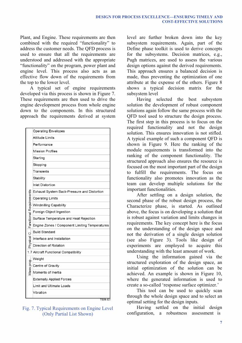
Plant, and Engine. These requirements are then combined with the required “functionality” to address the customer needs. The QFD process is used to ensure that all the requirements are understood and addressed with the appropriate “functionality” on the program, power plant and engine level. This process also acts as an effective flow down of the requirements from the top to the lower level.
A typical set of engine requirements developed via this process is shown in Figure 7. These requirements are then used to drive the engine development process from whole engine down to the components. In this structured approach the requirements derived at system
Fig. 7. Typical Requirements on Engine Level (Only Partial List Shown)
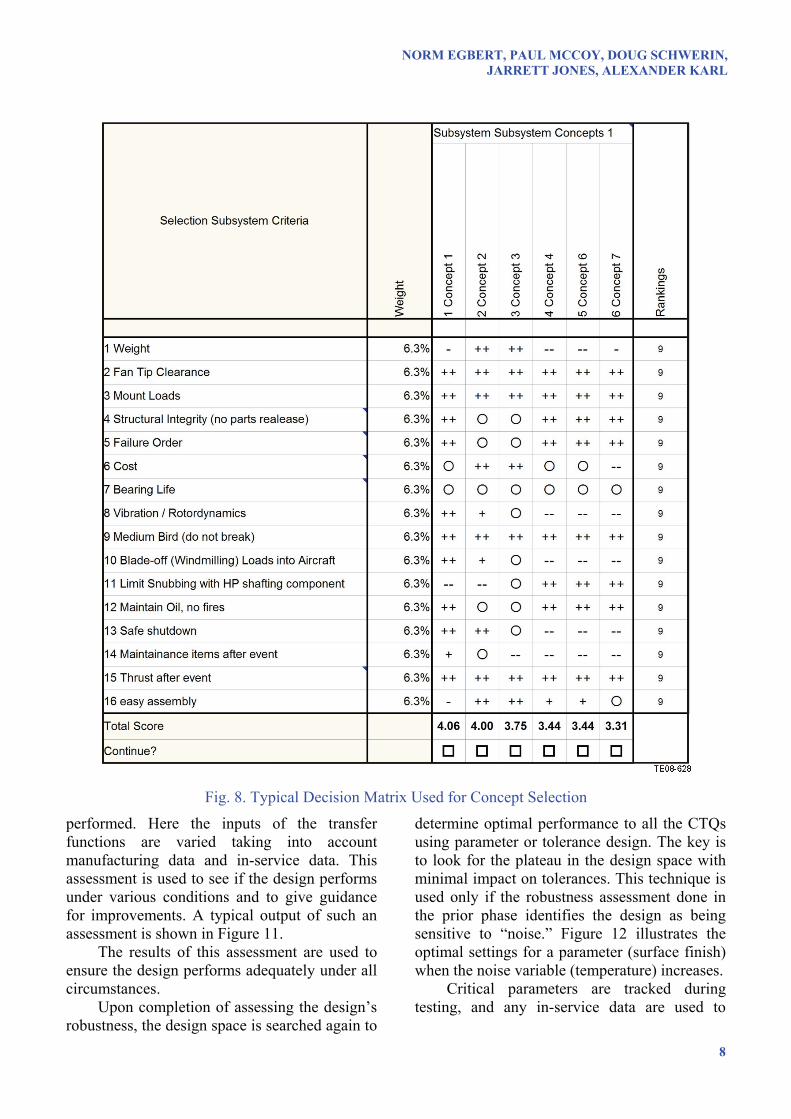
level are further broken down into the key subsystem requirements. Again, part of the Define phase toolkit is used to derive concepts for the subsystems. Decision matrices, e.g., Pugh matrices, are used to assess the various design options against the derived requirements. This approach ensures a balanced decision is made, thus preventing the optimization of one attribute at the expense of the others. Figure 8 shows a typical decision matrix for the subsystem level
Having selected the best subsystem solution the development of robust component solutions again follow the same process with the QFD tool used to structure the design process. The first step in this process is to focus on the required functionality and not the design solution. This ensures innovation is not stifled. A typical example of such a component QFD is shown in Figure 9. Here the ranking of the module requirements is transformed into the ranking of the component functionality. The structured approach also ensures the resource is focused on the most important part of the design to fulfill the requirements. The focus on functionality also promotes innovation as the team can develop multiple solutions for the important functionalities.
After settling on a design solution, the second phase of the robust design process, the Characterize phase, is started. As outlined above, the focus is on developing a solution that is robust against variation and limits changes in requirements. The key concept here is the focus on the understanding of the design space and not the derivation of a single design solution (see also Figure 3). Tools like design of experiments are employed to acquire this understanding with the least amount of work.
Using the information gained via the structured exploration of the design space, an initial optimization of the solution can be achieved. An example is shown in Figure 10, where the generated information is used to create a so-called ‘response surface optimizer.’
This tool can be used to quickly scan through the whole design space and to select an optimal setting for the design inputs.
Having settled on the initial design configuration, a robustness assessment is
NORM EGBERT, PAUL MCCOY, DOUG SCHWERIN, JARRETT JONES, ALEXANDER KARL
8
Fig. 8. Typical Decision Matrix Used for Concept Selection
performed. Here the inputs of the transfer functions are varied taking into account manufacturing data and in-service data. This assessment is used to see if the design performs under various conditions and to give guidance for improvements. A typical output of such an assessment is shown in Figure 11.
The results of this assessment are used to ensure the design performs adequately under all circumstances.
Upon completion of assessing the design’s robustness, the design space is searched again to
determine optimal performance to all the CTQs using parameter or tolerance design. The key is to look for the plateau in the design space with minimal impact on tolerances. This technique is used only if the robustness assessment done in the prior phase identifies the design as being sensitive to “noise.” Figure 12 illustrates the optimal settings for a parameter (surface finish) when the noise variable (temperature) increases.
Critical parameters are tracked during testing, and any in-service data are used to

DESIGN FOR PROCESS EXCELLENCE—ENSURING TIMELY AND COST-EFFECTIVE SOLUTIONS
9
Fig. 9. Typical QFD on Component Level
Fig. 10. Example Response Surface Optimizer to Define the Best Initial Solution

NORM EGBERT, PAUL MCCOY, DOUG SCHWERIN, JARRETT JONES, ALEXANDER KARL
10
Fig. 11. Comparison of Noise Effect Versus Design Parameter Effect
Fig. 12. Picking Optimal Values for Variables
ensure the analysis matches observed data. Decisions are ultimately driven by statistical data that accounts for variation. Figure 13 illustrates a model prediction versus measured data, and shows the model prediction and in-service data cannot be assumed to be different.
By verifying the models with real data, decisions are made with a level of confidence and understanding of how the design will behave in service.
Copyright Statement The authors confirm that they, and/or their company or institution, hold copyright on all of the original material included in their paper. They also confirm they have obtained permission, from the copyright holder of any third party material included in their paper, to publish it as part of their paper. The authors grant full permission for the publication and distribution of their paper as part of the ICAS2008 proceedings or as individual off-prints from the proceedings.
Fig. 13. Hypothesis Testing
5 Conclusions DfPE is the Rolls-Royce methodology to ensure timely and cost-effective solutions to our customers. Although there are many improvement practices in our industry, we believe DfPE best utilizes our internal skills and expertise to effectively create robust designs. DfPE is the preferred vehicle our leadership team utilizes to drive Rolls-Royce along the continuum of process and product improvement, as demonstrated in this paper. As we continue to Define, Characterize, Optimize, and Verify our product designs, Rolls-Royce will continue to drive new products to the market that focus on meeting the customer's needs.
References [1] Fellenstein, S. Dishing Up Success: Six Sigma Helps
Create GE’s Latest Dishwasher. Quality in Manufacturing. Oct 1999.
[2] Woodford, D. Design for Six Sigma - IDOV Methodology. iSixSigma.com. 19 Aug 2002. <http:// www.isixsigma.com/library/content/c020819a.asp>.
[3] Simon, K. What Is DFSS?. iSixSigma.com. 22 Jul 2002. http://www.isixsigma.com/library/content/ c020722a.asp.
[4] Watson-Hemphill, K. Designing Financial Services with DMEDI. iSixSigma.com. 1 Jan 2004. <http:// finance.isixsigma.com/library/content/c040101b.asp>.