Embed Size (px)
Citation preview

1
CHAPTER
DESIGN FOR TIME TO MARKET
Nosa. F. O. Evbuomwan
1. INTRODUCTION
The success of any product is determined to a large extent by the customers
and users within the intended market place. This is more critical for
products that thrive mainly on `market pull’. Fashion and style products
traditionally are influenced by the speed at which they get to the market
place, but in today’s market, many engineering products are now also faced
with increasing fierce competition, based on the speed at which they get to
the market place. Maximising the paralleling of the various design and
other engineering activities, during product development, as well as aiming
to increase the speed to market and thus reducing the product development
cycle time in a modern manufacturing environment, represents a true
concurrent engineering imperative.
Several definitions have been given to Concurrent Engineering, the
prominent one being that given by Winner et al1, who define Concurrent
Engineering as a systematic approach to the integrated, concurrent design
of products and their related processes, including manufacture and support.
This approach is intended to cause developers, from the outset, to consider
all elements of the product life cycle from conception through disposal,
including quality, cost, schedule and user requirements. Concurrent
Engineering has been the subject of discussion in several research papers,
conferences and books2-10. It is rapidly gaining ground particularly in the
manufacturing industry, and more recently in the construction and
petrochemical sectors as a progressive approach for ensuring
competitiveness and survival in the market place. A number of issues
constitute the ethos of concurrent engineering. Prominent amongst these
are: (i) the need to improve and maintain the quality of a product, (ii) the
reduction of product development costs, (iii) the removal of barriers (walls)
between product development groups, (iv) responding proactively to
customers, (v) bringing downstream issues such as manufacturing,
production, operation, maintenance, testing, use, etc., which impinge on the
design process, upstream to the design stage, and (vi) maximising the
2
paralleling of the various design and other engineering activities, during
product development as well as increasing the speed to market, thus
reducing the product development cycle time.
Time to market can generally be defined as the elapsed time between
product definition and product availability. The current wave and
emergence of new and improved products, extensions and expansions of
product lines, revisions and enhancements of products, creates additional
pressures on manufacturers to keep a steady stream or flow of new
products into the market place11. It is well established that any delays in
bringing a product to market, results in greater losses of profit. Hence
designing products for fast time to market, ensures the achievement of
optimum profitability10. A key influencing factor in achieving `Time to
Market’, is the design process, which has significant impacts on the
downstream functions of product development. Faulty, hurried or
inadequate product definition and design, usually results in design changes
in the form of engineering change orders (ECO’s), which are always very
costly in both time and money. Furthermore, the later these design changes
are implemented in the development cycle, the more costly the
implementation. Time to market is also dependent on the speed of
movement of design information across the company. This can be
enhanced by the use of computer networking technologies. Research by
Kusiak and Yang12 concluded that the implementation of concurrent
engineering, although may prolong the initial stages of design, does reduce
the overall design cycle (i.e. leads to shorter overall design cycle).
This chapter therefore will aim to address within the context of
concurrent engineering, the various issues which relate to designing for
time to market. It will begin by discussing the goals, objectives and the
need for designing for time to market. The benefits as well as the general
requirements for achieving time to market will also be elucidated. Design
Function Deployment (DFD) a concurrent engineering design system, will
then be introduced as a platform for designing for time to market. Further
discussions will also cover tools needed for designing for time to market,
as well as their management during product development.
2. GOALS, OBJECTIVES AND NEED FOR DESIGN FOR
TIME TO MARKET
This section will focus on key aspects relating to necessary goals and
objectives to be considered in designing for `Time to Market’. The section
will also address the rationale for design for Time to Market, and why it is
necessary for companies to adopt this approach to product development.

3
2.1 Goals and Objectives
The goals and objectives of designing for time to market are closely
aligned to concurrent engineering goals and include inter-alia the following 13: (i) the need to effectively compete in a global market place, (ii) the
necessity of reducing cycle time and cost, (iii) the need to improve quality
of product and to develop defect free products and services, (iv) to enable
flexibility, manufacturability and reliability both of the design process and
the product, (v) to increase product customisation and the number of
product options, (vi) to take advantage of new manufacturing strategies and
(vii) to achieve cost efficient design flexibility.
2.2 Need
A key reason to adopt the approach of designing for time to market, is due
to the fact that delayed introduction of new products to the market place,
reduces the lifetime profit potential of the products. The research by
McKinsey and Co. has shown that a product that is six months late to the
market will miss out on one third of the potential profit over the product’s
lifetime 11, 14, 15. Such delay in product introduction to market also makes it
harder for manufacturers to enter the market against an established
competitor. Companies constantly face the challenge to cope with
international competition, as well as competing on the basis of fast time to
market. For companies to succeed in their endeavour to remain
competitive, they need to adopt a design for fast time to market strategy.
3 BENEFITS OF DESIGN FOR TIME TO MARKET
Justification for adopting a design for fast time to market strategy, relates
to the financial benefits that can accrue to any particular company that
embarks on such endeavour. Such benefits include the following 16, 17: (i)
the extension of the period of product sales, (ii) the possibility of gaining
more customers and an increase in market share, (iii) the possibility of
higher profit margins and the enjoyment of more pricing freedom, (iv) the
exploitation of technical opportunities by synchronising product
development with latest technology, (v) the possibility of improving
company culture, as design for time to market becomes a company wide
attitude, (vi) the possibility of gaining an early access to the market, which
can give freedom to set higher prices and capture larger markets, (vii) the
enablement of using new technologies and fresh market information, (viii)
4
the volume of sales can be built up over the entire life cycle of the product
and (ix) unforseen problems can be reduced and product predictability can
be improved.
4 GENERAL REQUIREMENTS FOR DESIGN FOR TIME TO
MARKET
To ensure success in designing for time to market, certain general
requirements need to be addressed. These represent strategic initiatives to
be implemented within an enterprise and are discussed under the broad
headings of (a) Top Management Commitment, (b) Organisational
Integration, (c) Use of Vendors and Suppliers, (d) Use of Computers and
Technology and (e) Market Strategies.
4.1. Top Management Commitment
For the successful achievement of `Time to Market’, it is needful for the
top management in an enterprise to provide an environment which
encourages faster new product introduction. They should provide computer
based tools and systems as well as a vision of the future and a time to
market goal, to support the adoption of flexible and robust development
methodologies. It should also be the prerogative of top management to
ensure clear communication within project groups and organisational focus
on set goals and tasks.
4.2. Organisational Integration
Within the overall organisation, there should be clear, open, timely and free
flowing communications flourishing amongst the various divisions and
disciplines responsible for product development. These product
development teams must ensure clear understanding of customer
expectations and continuous customer contacts18. Close collaboration
should be established between the company’s development, production and
commercial functions. The company’s modus operandi should be improved
by the formation of multi-functional teams to facilitate the management of
an integrated design and manufacturing process. It is also important that
top management, treats each discipline in the organisation with equal
importance. Ensuring `Time to Market’ also requires the improvement of
two way and frequent communication amongst the development teams. All
life cycle aspects impinging on the product development process should of
necessity be integrated, as product development teams are constructed.

5
This will also involve integrating downstream factors into upstream
problem solving19. Furthermore, an organisational environment should be
created and fostered, where change and innovation occur naturally, with the
aim to minimize the amount of work and rework to be done in developing
a product.
4.3. Use of Vendors and Suppliers
It is imperative that in order to achieve early `Time to Market’, vendors and
suppliers, should be included early in the product development process. A
systematic view of the innovation/development process should be adopted,
involving all parties in the development process. It is expected that this
team, will use common, consistent, accurate and complete design data.
4.4. Use of Computers and Technology
In a modern manufacturing enterprise, the process of integrating the
organisation, cannot be done without the aid of computers. There is hence a
need for the integration of computerised information systems within such
companies, to support the early `Time to Market’ initiative. Such
computerised systems should inter-alia, provide and support open
communication amongst the various divisions within the organisation.
They should enable : (1) early sharing of information, (2) automation
(computerisation) of the design process and (3) the adoption of
manufacturing strategies aimed at reducing manufacturing lead time20.
Another requirement of the system is the support of advanced technologies,
which enable information flow, provide information about new
technologies and developments, as well as supporting tools to improve
product development and speed of the design department. Such new
technologies should be adopted to give employees the most current proven
tools to do their jobs.
4.5. Market Strategies
The successful achievement of designing for `Time to Market’
imperatively requires an understanding and knowledge of the customers
and users within the specific or general market outlets for the proposed
product. The emerging windows of opportunity, risks and opportunities as
well as the necessary trade-offs to be made between time, quality and cost,
need to be clearly understood. In this regard, it is incumbent on a
manufacturing company to: (i) carry out adequate market surveys and

6
strategic explorations, (ii) clearly define key attributes of competitive
strategy, (iii) when necessary, focus on a series of incremental
improvements in the product rather than new designs and (iv) make
available market information about new products to designers/engineers.
5 FUNDAMENTAL ISSUES AND FACTORS AFFECTING
DESIGN FOR TIME TO MARKET
Depending on the particular type of product, the product planning strategy
adopted and the particular approach to be utilised for designing for time to
market, certain issues which are fundamental, need to be addressed. These
are discussed below under the following headings :
(i) Modularisation during conceptual design, (ii) Overlapping and
Resequencing of Activities, (iii) Integration of Product Development
Activities, (iv) Product Classification, and (v) Strategic Product Planning.
This section concludes with a summary of general issues and factors
affecting design for `Time to Market’ which should be taken into account
within an enterprise in seeking to achieve the objective of early time to
market.
5.1. Modularisation During Conceptual Design
The conceptual design of a product, to a large extent can decide how fast a
product gets to the market. Key issues to be addressed, include : (i) what
functions are to be provided by the product and (ii) the interrelationships
between the functions and deployment of the functions to different parts of
the product. Making the correct decisions at the conceptual design stage is
critical to shortening the design cycle. A key decision to be made during
conceptual design in support of time to market, is the modularisation of the
design of the product. This can involve the division of the product into
modules (subsystems, components or parts), based on the modularisation
(decompositions) of the desired functions of the product. Each of the
modules and submodules, can then be developed concurrently, thus
permitting overlapping of activities and hence reducing the length of the
design process, while preserving coupling among design activities. The use
of appropriate module construction methods, will promote the progress of
parallel design teams working on each module. Standard components can
be used in the product, and thus concentrating efforts on the most
important product characteristics. The above modularisation process, can
also enable quick update of designs. In modularising designs, care should
be taken to ensure that, design concepts are developed to be insensitive to

7
minor changes in the interfaces between modules. Features of interaction
across and between modules that have an effect on product development
speed, must be resolved.
5.2. Overlapping and Resequencing of Activities
The product development process is characterised by the performance of
many design activities. During product development, it is needful for these
activities (tasks) to be divided and their interdependencies, established. In
most companies, these activities tend to be performed in a sequential
manner, with the engineers being oblivious to the inherent coupling
between the activities. The result of this, is costly engineering changes. In
sequential design, downstream activities start only after receiving finalised
information from their preceding activity. In order to accelerate the product
development process within the context of concurrent engineering and
designing for time to market, the coupling between activities, need to be
removed. This is to enable the performance of the activities in a parallel
(simultaneous) manner. In this case, each activity can proceed without
waiting for any information from a preceding activity. This requires
flexibility and focus from all participants in product development. In
instances where, coupling between activities cannot be completely
removed, the approach plausible, involves the overlap of the activities,
through frequent exchange of preliminary design information21. Such
overlapping process enables downstream activities to begin early by using
the preliminary design information from preceding activities. Overlapping
activities of the different phases of product development enhances fast
cycle development of new products22.
5.3. Integration of Product Development Activities
A key issue in achieving fast time to market, involves the integration of all
activities impinging on the product development process, and adopting a
co-operative product development approach23. The integration should be
based around people, information, computing technologies and tools. The
integration process should therefore support extra input at the early stages
of the product development process, particularly from downstream issues
(manufacturing, testing, service, etc.).
5.4 Product Classification

8
The variation between different products primarily arises as a result of the
different disciplines (mechanical, electronic, civil, chemical, etc.) from
which they are developed. Within each discipline however, product
variation can also be attributed to other factors such as : the intended
market segment, knowledge available, the integration of disciplines (e.g. as
in mechatronic design), the design process and manufacturing capabilities.
The nature of bounding constraints, customer demands and competition in
the market place, can also result in various product classifications. Such
product classifications that have emerged within the recent past are
discussed below24 - 26.
5.4.1. Static Product Designs. These are products whose market share is
generally undiminishing and little or no changes are being demanded in the
product. They are usually based on well known design concepts, and are
hence considered to be conceptually static products. For such products,
releasing them early to the market will not necessarily provide a
competitive advantage.
5.4.2. Dynamic Product Designs. These products tend to have a limited
life before the next generation supercedes it. In this case, developments are
focussed on the product, involving the development of new, radical and
alternative designs. Products belonging to this class, are generally
considered to be conceptually dynamic. In looking at the dynamic - static
spectrum of products, Clausing25 highlights the following types of products
sandwiched between the two extremes :
Genesis Product - This is an original product that has no previously related
product, and usually leads to the evolution of diverse families of products.
Radical Product - This is a product which although may at the higher
(concept) level of abstraction exhibit similarities to previous designs, but is
radically different in the final designs of the subsystems.
New Product - This is usually less than a radical product, and involves the
use of a new or an alternative technology in the development of an already
existing product.
Clean Sheet (Generational) Product - A clean sheet generational product is
usually characterised by a major step forward, and the design process
commences from a clean sheet of drawing paper, with little reference or
relationship to prior designs. The genesis, radical and new products are by
definition clean sheet designs.
Market-Segment Entry (New) Product - A market-segment entry product
moves a company for the first time into a new market segment, following

9
an earlier new (or radical) product. This is associated with the staggered
window of opportunity case discussed below, in the next subsection.
Market- Segment Entry (Generational) Product - This form of product is a
new product in a market segment following after a previous product in the
same market segment.
Associated Product - This is the type of product that changes some
technologies to provide a different capability, resulting in an entry into a
somewhat different market segment. An example is the case of laser
printers, which are based on xerographic copiers.
Variant Product - Variant products are those which are based on relatively
small changes on the base product. They usually include feature
enrichment or removal, dimensional magnification or downsizing, and
cost/performance upgrades.
Customised Product - Customisation of products extends over a range from
adding brand names to fairly major changes on a product for specific
customers. Customised products tend to have a limited role in the general
subject of product development.
5.4.3. Overconstrained Products. These tend to be products which exist
in the high technology markets. Here, the design process evolves around
analysing alternative design proposals until the correct (or most acceptable)
solution is found. Overconstrained products are usually subjected to several
constraints of function, materials, manufacturing processes, some of which
might be conflicting, and the product undergoes several analysis and trade-
offs. In this case, major changes in the product concept rarely occurs.
5.4.4. Underconstrained Product Designs (Ideas Centred). In the case
of underconstrained designs, the design activity is centred around bringing
products into the market to satisfy market demands. There are usually not
very many constraints, and the designer has ample room for innovation.
The focus here is usually on the product concept, and materials and
techniques are chosen to satisfy the required function and recognisable
market style. Most industrial designs fall into this category, and
development is on aesthetics, ergonomics and functionality.
5.4.5 Underconstrained Product Designs (Skill Based). This form of
designs focus on the manufacturing aspects of product development.
Efforts are usually concentrated on the capabilities and skills available in a
company.

10
5.4.6 Complex Products. Complexity in design and product
development can be examined from a number of viewpoints. If a complex
product is considered from the viewpoint of a complex system, then it can
be described as a product exhibiting complexity in shape and size, having
many interacting elements (subsystems, components and parts), which can
exist in different and perhaps changing states and which influence each
other. The time taken to design and develop the many constituent
interacting elements can also be considered to be contributory to a
product’s complexity.
5.4.7 Simple Products. A simple product can be described as one
having a simple shape and/or size, few interacting or possibly non-
interacting elements (subsystems, components and parts), which generally
exist in similar and perhaps non-changing states, with little or no influence
on each other, and which can be designed and developed within a relatively
short time.
The above classification can be schematically represented in the form of a
cube as shown in Figure 1. This cube comprises eight smaller cubes
representing different scenarios of product classification. They are : Cube 1
- Static-Simple-Underconstrained (SSU), Cube 2 - Static-Complex-
Underconstrained (SCU), Cube 3 - Dynamic-Simple-Underconstrained
(DSU), Cube 4 - Dynamic-Complex-Underconstrained (DCU), Cube 5 -
Static-Simple-Overconstrained (SSO), Cube 6 - Static-Complex-
Overconstrained (SCO), Cube 7 - Dynamic-Simple-Overconstrained
(DSO) and Cube 8 - Dynamic-Complex-Overconstrained (DCO)
FIGURE 1. The Three Dimensional Product Classification Matrix
1
2
5 7
8
3
4
6
SIMPLE
COMPLEX
STATIC DYNAMIC
UNDER-CONSTRAINED
OVER-CONSTRAINED
11
5.5 Strategic Product Planning
In designing for `time to market’, an issue that needs to be addressed is
how a company can go about strategically planning its products for the
various market segments and outlets. This issue of strategic product
planning will be examined primarily from two dimensions of what can be
referred to as Product Design Input and Product Design Output. It will also
be examined from the viewpoint of how the interaction of product
complexity and product uncertainty affects the need for a company to
proactively respond to the market. The discussions in this subsection draws
upon the work of Rajczi27.
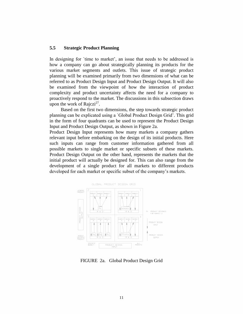
Based on the first two dimensions, the step towards strategic product
planning can be explicated using a `Global Product Design Grid’. This grid
in the form of four quadrants can be used to represent the Product Design
Input and Product Design Output, as shown in Figure 2a.
Product Design Input represents how many markets a company gathers
relevant input before embarking on the design of its initial products. Here
such inputs can range from customer information gathered from all
possible markets to single market or specific subsets of these markets.
Product Design Output on the other hand, represents the markets that the
initial product will actually be designed for. This can also range from the
development of a single product for all markets to different products
developed for each market or specific subset of the company’s markets.
FIGURE 2a. Global Product Design Grid

12
The interaction between the two axis of the matrix and the possible
location and movements by companies within any of the quadrants, is
driven principally by two forces (factors), namely : Opportunity Risk and
Right Product Risk. Opportunity Risk refers to the situation where a
window of opportunity exists, whereby a company must respond to a new
or changing market within a certain period of time, or risk losing the
opportunity in that market. If the windows of opportunity are small, then
we have a high risk situation, whereas if the window of opportunity is
large, we have a low risk situation. In situations where there are small
windows of opportunity (high risk), companies tend to be forced to choose
product strategies whereby only a few specific markets are polled for input.
Furthermore, the alignment of small windows between markets also affect
product strategy. Two forms of alignments are discussed here, that is
Stacked Windows and Staggered Windows.
For Stacked windows (i.e. windows which are open for the same or
similar periods of time), companies would need to choose a strategy based
on Quadrant 2 (Figure 2b), while for Staggered windows(i.e. windows
which are open at different periods of time), a company should choose a
strategy based on Quadrant 3 (Figure 2b). In this case, initial products can
be sold to few specific markets which they are designed for. Subsequently,
the initial product can be taken to other markets as the windows open. This
tend to create some form of flexibility for a company, as time is made
available for it to design specific products for specific markets.
FIGURE 2b. Opportunity Risk Matrix
In the case of Right Product Risk, this means the risk taken by a
company by not providing the exact product each market wants. High right
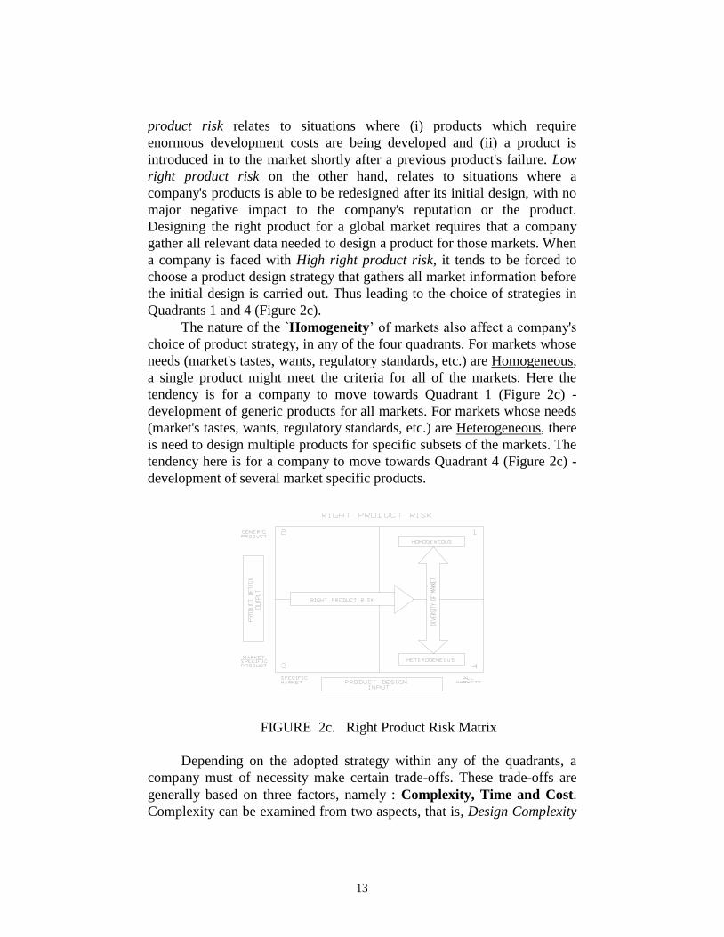
13
product risk relates to situations where (i) products which require
enormous development costs are being developed and (ii) a product is
introduced in to the market shortly after a previous product's failure. Low
right product risk on the other hand, relates to situations where a
company's products is able to be redesigned after its initial design, with no
major negative impact to the company's reputation or the product.
Designing the right product for a global market requires that a company
gather all relevant data needed to design a product for those markets. When
a company is faced with High right product risk, it tends to be forced to
choose a product design strategy that gathers all market information before
the initial design is carried out. Thus leading to the choice of strategies in
Quadrants 1 and 4 (Figure 2c).
The nature of the `Homogeneity’ of markets also affect a company's
choice of product strategy, in any of the four quadrants. For markets whose
needs (market's tastes, wants, regulatory standards, etc.) are Homogeneous,
a single product might meet the criteria for all of the markets. Here the
tendency is for a company to move towards Quadrant 1 (Figure 2c) -
development of generic products for all markets. For markets whose needs
(market's tastes, wants, regulatory standards, etc.) are Heterogeneous, there
is need to design multiple products for specific subsets of the markets. The
tendency here is for a company to move towards Quadrant 4 (Figure 2c) -
development of several market specific products.
FIGURE 2c. Right Product Risk Matrix
Depending on the adopted strategy within any of the quadrants, a
company must of necessity make certain trade-offs. These trade-offs are
generally based on three factors, namely : Complexity, Time and Cost.
Complexity can be examined from two aspects, that is, Design Complexity

14
and Co-ordination Complexity. In general, the choice of a product strategy
affects design complexity. When market inputs are obtained from many
markets, this means more design complexity. Hence strategies based on
Quadrants 1 and 4, tend to result in higher design complexity (Figures 2d
& 2e). In this case, the only options available, is for the company to (i) look
for efficiencies in design (e.g. high or fast performance) and (ii) carry out
modular designs of the complex products. The co-ordination complexity of
a product design's maintenance and evolution increases with the number of
products designed. Hence the adoption of strategies based on Quadrants 3
and 4, results in higher co-ordination complexity.
In the case of Time, the trade-off borders on time required to
introduce a product to all markets vis-à-vis that required to introduce a
product to a single or specific subsets of markets. If therefore there is need
to introduce products in key markets quickly, then a company can choose
strategies based on Quadrant 2 or 3 (see Figures 2d & 2e). This minimizes
the time spent introducing the first product to the first market, and less time
is spent upfront in the early stages of product development. More
engineering changes, however occur. On the other hand, if the need is to
introduce a product in all markets as quickly as possible, then choosing a
strategy in Quadrant 1 or 4 (see Figures 2d & 2e), seems to be more
appropriate. In this case, more time is spent upfront in the early stages of
product development, the result of which is lesser engineering changes.
Cost principally relates to the amount of work done as well as time
spent upfront in the early stages of product development. Choosing a
product design strategy in Quadrant 2 or 3, will minimize short term costs
by not polling all markets or developing a complex product design. Here,
cost to first market is reduced. Conversely, polling all markets will result in
high initial costs.
Summarily, factors which can be considered to affect product
development speed and early time to market, include the following : (1)
Market Input (customer/user survey), (2) Market Output (Product Outlet),
(3) Product Classification (Type, Nature, etc.), (4) Product Complexity, (5)
Product Uncertainty (window of opportunity, performance and customer
satisfaction), (6) The Design and Development Process,

15
FIGURE 2d. Advantages of Trade-offs
FIGURE 2e. Disadvantages of Trade-offs
(7) Downstream Processes (Manufacturing, Assembly, Testing,
Installation, etc.), (8) Ease and Speed of Manufacture and Assembly, (9)
Degree of Reliability before committal to Market, (10) Market Opportunity
(Low and High Risk), (11) Product Life Cycle and (12) Design Life Cycle.
DESIGN FOR TIME TO MARKET

16
6. DESIGN FUNCTION DEPLOYMENT - A CONCURRENT
ENGINEERING DESIGN SYSTEM
The development of Design Function Deployment (DFD) was driven by
the need for a design system that will enable the design and manufacture of
not only high quality and performance products, but those which are well
suited for their intended purpose, affordable and satisfactory to the
customer. The research involved in this development, benefited from
research into Quality Function Deployment (QFD)28-31, Design
Philosophies, Models, Methods and Systems32-33, and Concurrent
Engineering34-38.
Design Function Deployment, DFD24, 39-40 has been developed as a
comprehensive design system, to incorporate the features of a prescriptive
design model, and associated design methods for the integration of
manufacturing, use and other downstream issues into design, and thus
enabling a concurrent engineering approach to product, systems or process
development. It uses the fundamental concepts of QFD, to enable the
establishment, focussing and satisfaction of customer requirements
throughout the product development process.
The goals of DFD inter-alia, include the following : (1) to recognize
the importance of customer requirements within a specified market, (2) to
ensure the change from the `over the wall’ approach to team approach in
design and product development, (3) to provide a platform for concurrent
engineering, (4) to generate the design solution space, (5) to facilitate
design retrieval (aka case-based reasoning and design) of previous design
solutions, (6) to maximize the knowledge about performance of product at
the design stage, (7) to minimize or eliminate downstream engineering
changes, (8) to establish robustness of design, (9) to utilize new materials
and technologies and (10) to ensure quality through design.
The design model of DFD as shown in Figure 3 proceeds through
five stages of (i) Establishment of customer requirements, and
determination of design specifications and constraints, (ii) Development of
conceptual solutions called `Architectures', (iii) Establishment of viable
variant solutions for each plausible architecture, called `Layouts', (iv)
Establishment of viable materials and corresponding manufacturing
processes for each viable layout and (v) Establishment of production plans
for each viable layout. The system is being implemented in a three layer
framework, as shown in Figure 3.

17
FIGURE 3. The Structure of the Design Function Deployment System
(Adapted from24 )
The first layer represents the design process model described above,
the second layer represents the several design methods, tools and
techniques employed as the design progresses from stages 1 to 5, while the
third layer contain numerous knowledge bases and databases, which can
act as repositories for corporate knowledge, historical design data, proven
technologies as well as for generic materials and manufacturing processes.
6.1. The Design Matrix of Design Function Deployment
The design matrix in DFD, is examined from a three dimensional
viewpoint. The first dimension (z-axis) is referred to here as the
morphology of the

18
design process, and it represents the five stages shown in level 1 of the
DFD structure, that is, the minimum prescribed path to be followed during
the design process. The second dimension (y-axis) is referred to as the
anatomy of the design process within DFD, and this represents the design
activities implicitly performed within each of the five stages of DFD. The
level 2 of the DFD Structure (Figure 3), contains design modules
(methods) which are used in performing the above activities within each of
the five stages of DFD. These modules are key to the DFD system and thus
represent the third dimension (x-axis) of the DFD design matrix. The three
dimensional matrix is shown in Figure 4. It shows the global view of the
design matrix within DFD, and it explicates the interactions of the three
dimensions. It should be noted that, it is only the morphological dimension
of the design process (i.e. DFD design stages), that represents a
chronological ordering of distinct steps and that the other two dimensions
do not represent any chronological ordering of distinct steps. There would
hence be continuous feedback, iteration and revision in performing any of
the design activities while using any of the design modules (methods or
tools). The matrix can be used to identify the activities that need to be
performed at any of the DFD design stages as well as the accompanying
tools that can be used for any of the activities, depending on the nature and
type of product or designs.
6.2. Design Function Deployment as a Concurrent Engineering
Design System
This section discusses Design Function Deployment (DFD) as a concurrent
engineering design system, within the context of its satisfaction of the main
goals and general requirements of concurrent engineering. The DFD design
system has been developed to support product development teams in
achieving early time to market, by enabling the integration of all life cycle
and functional issues under one umbrella. The DFD system at level 1
provides a structured format for carrying out the design process in a
planned and controlled way. This ensures that all necessary information
generated, analysis performed, evaluations done and decisions made, are
recorded and documented accordingly. The first stage of the design process
in level 1 ensures that elicited requirements (customer, user,
manufacturing, finance, marketing, etc.) are all considered in an integrated
and concurrent manner, before translation into design requirements.

19
FIGURE 4 The Three Dimensional Design Matrix
Level 2 of the DFD system contains many design modules (methods and
techniques) which can be used in a parallel manner, as the design activity
proceeds from conceptual to detailed design stages. These modules in their
use, ensure that design concepts are not only functional, but can be
manufactured, assembled, sold and used to the satisfaction of customers.
The third level of the DFD system contains databases and rulebases, some
of which are associated with the level 2 modules. These modules store
various design knowledge and information in the form of design rules,
materials and manufacturing data and previous design information that can
be retrieved and used for new designs. The databases and rulebases will
ensure concurrent access to both past and present design information by all
interest groups involved in the product development process. This will help
to remove unnecessary interfaces between the groups, and hence reducing
delays in the product development process. The link of the level 3 modules
with levels 1 and 2 in the DFD structure, also helps in the implementation
of concurrent engineering, by the integration of conceptual design,

20
geometric modelling, materials and manufacturing process selection, as
well as permitting the increase of product performance knowledge in the
early stages of the design process, when costs are committed.
7. DESIGN FOR TIME TO MARKET WITHIN DESIGN
FUNCTION DEPLOYMENT
The aim of this subsection, is to enunciate a rational approach for
paralleling the design process within the taxonomy of the design stages of
Design Function Deployment. The benefits of this approach, in terms of
separating the overall design into modular groups and activities, managing
the complexity and interactions between the separate design tasks and
subsequent reduction of the design cycle will be discussed.
7.1. Review of Design and Project Management Techniques
The adoption of the concurrent engineering approach in product
development, implies that engineers, designers and product development
managers, have to cope with a larger amount of design data and
information. The scenario where the designers not only uses engineering
information, but additional information from other disciplines involved in
the product development process, leads to further complexity of the design
process. Engineers and designers in this present climate, therefore need to
adopt techniques for planning, organising and monitoring the large and
complex network of design tasks arising in the product development
process.
Over the years, several techniques have evolved for managing
complex and large projects as well as the design process. Such techniques
include : Directed Graphs (DG) 41, 42, Project Evaluation and Review
Technique/Critical Path Method (PERT/CPM) 43, 44, Structured Analysis
and Design Technique (SADT) 45, 46 and Design Structure Matrix (DSM).
The above three networking techniques (Directed Graphs, PERT/CPM and
SADT) suffer from size limitations and an inability to explicitly represent
circuits (coupling) of the design tasks. They are usually based on one way
progression along paths, with no feedback or iteration and no feedforward
of information part-way through task 41, 44. They tend to be used primarily
or documenting design practices and do not handle interactions that occur
within design tasks.

21
7.2. Design Structure Matrix (DSM)
The philosophy of the Design Structure Matrix (DSM) technique is that the
design project can be divided into individual tasks, and the relationships
and interactions among the tasks analysed to identify the underlying
structure of the project. There is some belief that studying relationships
between individual tasks can improve the overall design process, as well as
being an effective way of analysing alternative design strategies 47. DSM
with the aid of a graphical representation (matrix) uses the structure of
design information flow to guide the decomposition of the design activity.
In this matrix, the links and relations between the tasks are mapped out in
such a way that makes their interdependence explicit.
The design activity which consists of for instance m tasks, can be
represented as an m x m matrix. Each of the tasks are labelled along the
side of the matrix as row headings and across the top of the matrix as
column headings, in an identical manner. The matrix element aij is non-
zero if node i provides information to node j. A typical matrix is shown in
Figure 5a. Interpreting the task ordering as a time sequence helps to make
the timing of information flow explicit. The marked elements within each
row of the matrix identify the other tasks that must contribute information
for proper completion of the design.
FIGURE 5a. A Typical Design Structure matrix
In the matrix, marks below the diagonal represent information
transferred to later tasks (i.e. task A must be completed before task C);
while marks above the diagonal depict information which are fed to earlier
tasks (i.e. task G must be performed before task B). The primary goal of
design structure management is to find a sequence of these design tasks
which allows this matrix to become lower triangular.

22
Once the design process has been established into a design structure
matrix, the analysis proceeds in two separate stages, known as Partitioning
and Tearing 41, 44, 48. The process of partitioning aims at resequencing the
design tasks, in order to maximise the availability of information required
at each stage of the design process. Partitioning helps to identify tasks
which are coupled in a loop, and then clusters them as blocks on the
diagonal of the design structure matrix (Figure 5b). The strategies of the
partitioning algorithm include: scheduling independent design tasks as
early as possible and then simultaneously identifying tasks which are
coupled for further analysis. Once partitioning has placed the design
structure in a block-triangular form, the tearing analysis then begins. The
goal of tearing is to resequence within the groups (blocks) of coupled tasks
to find an initial ordering to start the iteration. The algorithms employed in
tearing includes tearing with shunt diagrams and tearing with heuristics.
This form of matrix discussed above, represents what is known as the
activity-activity incidence matrix.
FIGURE 5b. The Partitioned Design Structure Matrix
Other forms of incidence matrices have also been discussed by 49, 50.
These include the module-activity incidence matrix and the procedure
(formula)-parameter (variable) incidence matrix. In these two cases, the
analysis of the matrix, involves the use of suitable clustering algorithms 51,
52. Decomposition of the design process and using the algorithms described
above, has been considered to lead to the following advantages 50: (i)
separation of the overall design task into groups design tasks and/or groups
of modules and activities, (ii) potential activities that can be performed

23
concurrently are detected, (iii) the complexity of managing the design task
is reduced and (iv) the design cycle time is reduced.
7.3 Concurrent Design Within Design Function Deployment
The process of bringing design influencing downstream issues early
upstream to the design stage, as part of fulfilling the ethos of concurrent
engineering, does lead to an increase in the activities to be performed in the
product development process. This factor coupled with the basic idea of
shortening the product development cycle time, lends weight to the need to
manage the design process and the associated interactions and
complexities, more effectively. In Design Function Deployment, the
process of concurrent (parallel) design, is considered from two main
viewpoints, which are :(i) Concurrent design associated with the design
process (CDDP) though stages 1 to 5 and (ii) Concurrent design
associated with the design artifact (CDDA).
Considering the first case, that is, CDDP, the flow through the five
stages of DFD, as shown in Figure 6, represent the minimum prescribed
path (critical path) to be followed in the design process, and is generally
not subject to any form of concurrency. However, at each of the stages,
several design activities are performed, with some of them somewhat
repeated down the later stages, and in other situations somewhat
overlapping. It is these activities that can be explored for possible
concurrency, and to speed up the design process within each of the stages.
Tables 1 to 3 shows typical activities for each of the five stages of the DFD
design model.
Some of these activities (or design tasks) which take place in each of
the DFD stages, would be inter-disciplinary, relating to for instance
(marketing, design, manufacturing, finance, testing, etc.), while others will
be intra-disciplinary (stress analysis, geometric modelling, feature-based
design, thermal analysis, etc. - all within for instance the design group).
The above implies that the larger inter-disciplinary team would be involved
in the inter-disciplinary activities, while the smaller design team would be
responsible for the intra-disciplinary activities. Irrespective of whether
these activities are inter- or intra-disciplinary, it is needful to decompose all
the activities within each DFD stage and then to establish those that can be
done in parallel and those to be carried out serially to precede other
activities.

24
FIGURE 6. The Flow of the Design Process in Design Function
Deployment
In this concurrent design case, the applicable form of incidence matrix is
the activity-activity matrix, which can be employed at each of the DFD
stages. With this form of matrix, the triangularisation algorithm
(Partitioning and Tearing) can then be used to decompose the activities into
groups of activities, thus simplifying the entire design process and these
activities can then be sequenced in such a way as to speed up the product
development time. This results in the overlapping situation that occurs
between the inter- and intra-disciplinary activities as they are being
performed, with activities belonging to either of them being performed in
parallel or in series.

25
TABLE 1. Design Activities in Stages 1 and 2 of DFD
Stage 1 Stage 2 1. Elicit Requirements
2. Analyse Requirements
3. Categorise Requirements
4. Prepare Quality Plan
5. Derive Design Functions
6. Analyse & Group Design Functions
7. Set Target Values for Design
Functions
8. Complete Correlation Matrix
9. Complete Relationship Matrix
10. Rate Design Functions
1. Establish subsystems from stage 1
Design Functions
2. Generate and Synthesise concepts
(Architectures)
3. Derive Design Functions
4. Analyse & Group Design Functions
5. Set Target Values for Design Functions
6. Complete Correlation Matrix
7. Complete Relationship Matrix
8. Rate Design Functions
9. Explore Materials and Manufacturing
Processes
10. Evaluate each Architecture
11. Select viable Architectures
TABLE 2. Design Activities in Stages 3 and 4 of DFD
Stage 3 Stage 4 1. Generate Layouts for each
Architecture
2. Derive Design Functions for each
part of Layout
3. Analyse & Group Design Functions
4. Set Target Values for Design
Functions
5. Complete Correlation Matrix
6. Complete Relationship Matrix
7. Rate Design Functions
8. Materials Selection
9. Evaluate & Select Viable Layouts
10. Create Solid Models of Layouts
11. Finite Element Analysis/Mechanism
Analysis
12. FMEA/FTA Analysis
13. Robust Engineering Design
14. Evaluate against DF`Xs'
15. Select Optimal Layout
1. Establish Viable Materials and
Manufacturing Process
2. Derive Manufacturing Design Functions
for each part of Layout.
3. Analyse & Group Design Functions
4. Set Target Values for Design Functions
5. Complete Correlation Matrix
6. Complete Relationship Matrix
7. Rate Design Functions
8. Establish Critical Manufacturing
Processes
9. Manufacturing Process Planning
10. Simulate Manufacturing Process Plans
11. Assembly Planning
12. Rapid Prototyping
13. Evaluate against DFM, DFA and
DFDisassembly
14. Materials Resource Planning

26
TABLE 3. Design Activities in Stage 5 of DFD
Stage 5 1. Job Scheduling
2. Line Balancing
3. Batch Size Determination
4. Routing Procedures
5. Capacity Analysis
6. Planning for Inspection
7. Simulation of Production Plans
8. Layout, Machine and Tooling Procedures
It is worth noting that the number and type of activities that would be
carried out in parallel or in series would depend not only on the
engineering domain of the design, but also on the nature, type or class of
the product. In the second case, that is, CDDA, the performance of
concurrent design depends to a large extent on the type and nature of the
product. Products can generally be classified as static (fixed concept) or
dynamic (short life cycle and requires new concepts), as well as
overconstrained or underconstrained (could be ideas or skills based). For
this case, four forms of concurrent design are considered. The first form
involves the design of competing alternative architectures (at stage 2 of
DFD) in parallel, as shown in Figure 7 and the second form involves the
design of competing alternative layouts (at stage 3 of DFD) in parallel.
The third form of concurrent design relates to designing in parallel
the individual subsystems that constitute an architecture (between stages 2
and 3), while the fourth form is associated with the parallel design of the
individual parts of a particular layout (between stages 3 and 4). For the
third and fourth forms of concurrent design above, necessary interactions,
conflicts, dependencies and trade-off scenarios between either the
subsystems or parts, should be explored. Necessary steps can then be taken
to provide solutions to any bottlenecks. This can be done through a process
of elimination, combination, modification, transference, simplification and
standardisation of the subsystems or parts. Depending on the product type,
either one or a combination or all of the four forms of CDDA, will be
applicable. In the case of the third and fourth forms of concurrent design,
the applicable incidence matrix would be the module-activity matrix,
where module refers to either subsystems of an architecture or parts of a
layout.

27
FIGURE 7. Concurrent Design for Time to Market within Design
Function Deployment
The size of this matrix would depend on the scale and complexity of
the product. Discussions of these four forms of CDDA will be based on
Figure 1.
For static-simple (small scale)-underconstrained (SSU) products, the
second form of CDDA would be more applicable. In the case where the
SSU product has several and/or fairly sizeable parts that can be designed
independently and if considerable effort is required, then there would be
need to employ the fourth form of CDDA. In the case of static-
simple(small scale)-overconstrained (SSO) products (e.g. beverage cans),
no form of CDDA is applicable. The focus for manufacturers of such
products, is usually to improve the manufacturing process. The fourth form
may however be applicable, if a similar condition to that of SSU occurs.
For static-complex-underconstrained (SCU) and static-complex-
overconstrained (SCO) products, the third and fourth forms of CDDA, are
more applicable. The second form may also be applicable to SCU products,
if sufficient resources are available, or if the parallel design can be done by
a different arm or division of the enterprise. Dynamic products are to all

28
intents and purposes underconstrained products. In the case of dynamic-
simple-underconstrained (DSU) products, the first, second and fourth
forms of CDDA are more applicable, while in the case of dynamic-
complex-underconstrained (DCU) products, all four forms of CDDA are
applicable. For both innovative and creative designs, the four forms of
CDDA are also applicable, while in the case of adaptive and variant
designs, only the second, third and fourth forms of CDDA are relevant. It
should be noted that all the four forms of CDDA, go hand in hand with
CDDP.
7.4 Dimensionality of Concurrent Design in Design Function
Deployment
The employment of only CDDP, represents a one- dimensional case in
design concurrency, irrespective of the DFD design stage, and this relates
to SSO products. Here there is no occurrence of CDDA. When either of the
four forms of CDDA are employed in addition to CDDP, then we have a
two-dimensional case of design concurrency, occurring between stages 2
and 4. In the situation where either the third or fourth or both forms of
CDDA are employed in addition to either the first or second or both forms
of CDDA, in addition to CDDP, then we have a three-dimensional
concurrency case, as in DSU and DCU products. For SSU, SCU and SCO
products, the two-dimensional case predominates.
This research work is on-going, and the next stage of the work will
be focussed on how to implement the concepts developed in this section,
within the DFD software system. This is represented as the design
management module in the DFD software architecture shown in Figure 8.
Other research efforts will also go on in parallel as regards modelling
and simulating the design process within DFD using cases studies, as well
as testing the techniques with current practices in industry.
8. MANAGEMENT OF TOOLS FOR TIME TO MARKET
The objectives here are to examine (i) the goals of managing the tools and
resources and (ii) how the management process can be done in line with
concurrent engineering practices. In looking at how the management
process is carried out, the first issue to consider is that the tools and
resources required for each of the activities need to be established. After
this, the explication of the dependencies if any, between the tools, that is,
establish which tool has to be employed to precede another tool (e.g. solid
modelling before Finite element analysis) also need to be explored.

29
FIGURE 8 The Design Function Deployment System Software
Architecture
These dependencies will be influenced mainly by the dependencies that
might exist between each of the design activities. The goal of managing the
design activities is to establish which tasks can be done in parallel and
those that must of necessity be done in series. Having established the
precedence relationships of the design activities, the necessary tools and
resources that have to be employed for each task, can also be established,
using necessary task-tools/resources matrix relationships (tasks listed along
rows, and corresponding tools or resources listed along columns). What we
have here are two matrices of design task-design tools and design task-
resource incidence matrices, where the former shows the tools that are

30
needed to perform particular tasks and the later shows the resources needed
for particular tasks. For more efficient management, these relationships
have to be established for each design stage in DFD.
9. CONCLUSION
It is widely accepted in the manufacturing industry that the speed at which
a product gets to the market place, is a major factor affecting how a
company performs in the market place and represents a key basis for
competition. The main focus of this chapter therefore, has been to address
this major constituent of the ethos of concurrent engineering, that is, the
need to design products for early release to the market place. This has
involved a discussion of the meaning of `Time to Market’, the goals,
objectives, need for and benefits of designing for time to market.
The general requirements which form a basis for achieving the
objectives of design for time to market, have also been discussed. Design
Function Deployment (DFD) - a concurrent engineering design system,
which provides the framework for designing for time to market, was
comprehensively elucidated. Further discussions also involved how to
design for time to market within the platform of DFD. This included
discussions on product classifications, strategic product planning and
fundamental issues affecting design for time to market. The recommended
approach to designing for time to market, was explicitly enunciated. The
chapter concluded with discussions on tools needed to support the process
of designing for time to market, as well as their classifications and
management. The central theme of this chapter, that is, designing for
“Time to Market”, has been demonstrated to be a concurrent engineering
imperative.
10. REFERENCES
1. R. I. WINNER. ET AL., The Role of Concurrent Engineering in
Weapons System Acquisition, (IDA Report R-338, Institute of
Defense Analysis, Alexandria, Virginia, USA, 1988).
2. S.G. SHINA, IEEE Spectrum, July, 23 - 26 (1991).
3. J. R. HARTLEY, Concurrent Engineering (Productivity Press,
Cambridge, Massachusetts, USA, 1990).
4. J. MOTIMER and J. R. HARTLEY, Simultaneous Engineering, (The
DTI, Enterprise Initiative, London, UK, 1990).

31
5. D. P. CLAUSING, "Concurrent Engineering", Proceedings of the
Design and Productivity International Conference, Honolulu, Hawai,
February 6- 8, 1991.
6. S. N. DWIVEDI ET AL., Concurrent Engineering Approach to
Materials Processing (Minerals, Metals and Materials Society,
Warrendale, PA, USA, 1992).
7. Concurrent Engineering : Research and Applications, Edited by A. J.
Paul and M. Sobolewski (Concurrent Technologies Corporation,
Johnstown, PA, USA, 1994).
8. Concurrent Engineering Edited by A. J. Paul and M. Sobolewski
(Concurrent Technologies Corporation, Johnstown, PA, USA, 1995).
9. Concurrent Engineering & Electronic Design Automation, Edited by
S. Medhat (The Society for Computer Simulation International SCSI,
San Diego, USA, 1994)
10. C. S. SYAN and U. MENON, Concurrent Engineering : Concepts,
Implementation and Practice (Chapman & Hall, London, 1994).
11. J. T. VESEY,SAM Advanced Management Journal, Autumn, 26-33
(1991).
12. A. KUSIAK and H. YANG, “Modelling Design Cycles with
Stochastic Petri Nets”, in PED-Vol. 59, Concurrent Engineering,
(ASME, USA, 1992), 375 - 385.
13. J. A. EDOSOMWAN, “Achieving Product and Service Fast Time to
Market Objectives Through Technology Management”, in
Management of Engineering and Technology - PICMET ‘91, (IEEE,
NJ, USA, 1992), 211 - 213.
14. R. BALACHANDRA, “Some Strategic Aspects of Faster New
Product Introduction”, in Management of Engineering and
Technology - PICMET ‘91, (IEEE, NJ, USA, 1992), 226 - 229.
15. T. M. NEVENS ET AL, Harvard Business Review, 69, 3, 154-163,
(1990).
16. P. G. SMITH and D. G. REINERTSEN, Developing Products in Half
the Time, (Van Nostrand Reinhold, NY, USA, 1991).
17. A. VERHO AND V. SALMINEN, “Systematic Shortening of the
Product Development Cycle”, in International Conference on
Engineering Design, ICED ‘93, Edited by V. Hubka (The Hague,
August 17 - 19, 1993), 596 - 606.
18. D. E. WHITE and J. R. PATTON., “Accelerating Time-To-Market -
Methodology and Case Study Highlights”, in Management of
Engineering and Technology - PICMET ‘91, (IEEE, NJ, USA, 1992),
214 - 219.
32
19. D. G. SHENAS AND S. DERAKHSHAN, International Journal of
Vehicle Design, 13, 5/6, 533-541, (1992).
20. A. DE MEYER, “Shortening Development Cycle Times : A
Manufacturer’s Approach”, in Management of Engineering and
Technology - PICMET ‘91, (IEEE, NJ, USA, 1992), 220 - 224.
21. V. KRISHNAN, “Design Process Improvement : Sequencing and
Overlapping Activities in Product Development”. D.Sc Thesis, MIT,
September, 1993.
22. D. M. S. LEE, “Concurrent Engineering as an Integrated Approach to
Fast Cycle Development”, in Management of Engineering and
Technology - PICMET ‘91, (IEEE, NJ, USA, 1992), 238 - 241.
23. G. SOHLENIUS, Annals of the CIRP, 41, 2, 645-655, (1992).
24. N. F. O. EVBUOMWAN, “Design Function Deployment - A
Concurrent Engineering Design System”, PhD Thesis, City
University, London, September 1994.
25. D. P. CLAUSING, Total Quality Development - The Development of
Competitive New Products, (The American Society of Mechanical
Engineers Press, NY, USA, 1994).
26. A. J. MEDLAND, The Computer Based Design Process, (Kogan
Page, London, 1986).
27. K. RAJCZI, “Product Design Strategy in the Global Firm”, in
Management of Engineering and Technology - PICMET ‘91, (IEEE,
NJ, USA, 1992), 772 - 775.
28. J. R. HAUSER and D. P. CLAUSING, Harvard Business Review,
May-June, 63 - 73, (1988).
29. D. P. CLAUSING and S. PUGH., "Enhanced Quality Function
Deployment", in (Proceedings of the Design and Productivity
International Conference, Honolulu, Hawai, February 6- 8, 1991),
15 - 25.
30. Y. AKAO, Quality Function Deployment - Integrating Customer
Requirements, (Productivity Press, Cambridge, Massachusetts, USA,
1990).
31. R. KING., Better Designs in Half the Time, (GOAL/QPC, Methuen,
Massachusetts, USA, 1989).
32. S. FINGER and J. R. DIXON, Research in Engineering Design, Vol.
1, 51-67, (1989).
33. N. F. O. EVBUOMWAN ET AL, Journal of Engineering
Manufacture, Proceedings of the Institution of Mechanical Engineers,
210, B4, 301-320 (1996).
34. D. SRIRAM and R. LOGCHER, IEEE Computer, January, 64-65,
(1993).

33
35. Y. V. RAMANA REDDY, IEEE Computer, January, 12-16 (1993).
36. N. F. O. EVBUOMWAN ET AL, "A State of the Art Report on
Concurrent Engineering", in Concurrent Engineering : Research and
Applications, Edited by A. J. Paul and M. Sobolewski (Concurrent
Technologies Corporation, Johnstown, PA, USA, 1994), 35 - 44.
37. N. F. O. EVBUOMWAN and S. SIVALOGANATHAN, "The
Nature, Classification and Management of Tools and Resources for
Concurrent Engineering", in Concurrent Engineering : Research and
Applications, Edited by A. J. Paul and M. Sobolewski (Concurrent
Technologies Corporation, Johnstown, PA, USA, 1994), 119 - 126 .
38. A. JEBB ET AL, "Design Function Deployment - A Paradigm for
Concurrent Engineering", in Design to Manufacture in Modern
Industry, Edited by A. Jezernik (University of Maribor, Ljubljana,
Slovenia, 1993), 1, 78 - 85.
39. S. SIVALOGANATHAN ET AL, Design Studies Journal, 16, 4,
447-470 (1995).
40. S. SIVALOGANATHAN ET AL, Concurrent Engineering :
Research and Applications Journal, 3, 4, 257-270 (1995).
41. D. A. GEBALA and S. D. EPPINGER, "Methods for Analysing
Design Procedures", in DE-Vol. 31, Design Theory and
Methodology, (ASME, USA, 1991), 227 - 233.
42. F. HARARY, Graph Theory, (Addison-Wesley, Reading,
Massachusetts, USA, 1969).
43. J. D. WIEST and F. K. LEVY, A Management Guide to PERT/CPM,
(Prentice-Hall, Englewood Cliffs, New Jersey, USA, 1977).
44. S. D. EPPINGER ET AL, "Organising the Tasks in Complex Design
Projects", in Design Theory and Methodology, (ASME, USA, 1990),
39 - 46.
45. D. T. ROSS, IEEE Transactions on Software Engineering, SE-3, 1,
16-34 (1977).
46. D. T. ROSS, IEEE Computer Magazine, April, 25-34 (1985).
47. E. VON HIPPEL, Research Policy, 19, 407-418 (1990).
48. D. V. STEWARD, IEEE Transactions on Engineering Management,
EM-28, 3, 71-74 (1981).
49. A. KUSIAK and J. WANG, "An Efficient Algorithm for Organising
of Design Activities", Working Paper No. 91-31, Department of
Industrial Engineering, The University of Iowa, Iowa City, IA, USA,
1991.
50. A. KUSIAK and K. PARK, International Journal of Production
Research, 28, 10, 1883-1900 (1990).

34
51. A. KUSIAK and W. S. CHOW, IEEE Transactions on Systems, Man,
and Cybernetics, SMC-17, 4, 696-699 (1987).
52. A. KUSIAK, Intelligent Manufacturing Systems, (Prentice-Hall,
Englewood Cliffs, NJ, USA, 1990).
11. ACKNOWLEDGEMENTS
This work was supported by the Engineering and Physical Sciences
Research Council (EPSRC), UK, while the author was at the Engineering
Design Centre, City University, London.


![market [in] design](https://img.pdfslide.net/doc/110x75/62b96d7a7ff7027d87431555/market-in-design.jpg)