Embed Size (px)
Citation preview
UCL Engineering, Maintenance & Infrastructure 1–19 Torrington Place London WC1E 7HB
Design Guidance
For Mechanical, Electrical & Public Health
Services
DRAFT REVISION 6

Design Guidance for Mechanical, Electrical and Public Health Services / Revision 6 DRAFT 2
Amendment number
Description Date
1st Edition issue 1st Issue of Document
Sept 2005
2nd Edition issue Contact directory updated, M&E general revisions, and vertical transportation substantially revised.
August 2009
3rd Edition issue Contact directory updated, revisions to M& E sections
February 2011
4th Edition issue Revised to reflect updates to all sections May 2013
5th Edition issue Revised to reflect comments from Deputy Head of Engineering
Sept 2013
6th Edition Advance Issue
Draft Update Issued in advance as early information to Project teams. Will be subject to further change.
Jan 2017
Design Guidance for Mechanical, Electrical and Public Health Services / Revision 6 DRAFT 3
Contents A.1 Introduction ........................................................................................................... 7
A.2 The MEP Engineering Design Guide ..................................................................... 7
A.2.1 Best Value ........................................................................................................ 7
A.2.2 Objectives......................................................................................................... 8
A.2.3 Consultant Appointment ................................................................................... 9
A.2.4 Responsibilities for design and production information ..................................... 9
A.3 PROPERTY PORTFOLIO SERVICES .................................................................. 9
A.4 CONSULTATION AND ENGAGEMENT ............................................................. 10
A.4.1 Stakeholder Engagement ............................................................................... 10
A.4.2 Background on UCL’s Support structure ......................................................... 10
A.5 DESIGN STANDARDS ....................................................................................... 11
A.6 STAGE GATE APPROVALS ............................................................................... 12
A.7 WORK ON EXISTING BUILDINGS ..................................................................... 13
A.8 ENERGY CONSERVATION CONSIDERATIONS ............................................... 13
A.8.1 Energy efficiency measures to be included in the Project ............................... 14
A.8.2 Regulatory Considerations ............................................................................. 15
A.8.3 Environmental Issues ..................................................................................... 15
A.8.4 Passive Design Features ................................................................................ 15
A.8.5 Building Fabric ................................................................................................ 16
A.8.6 Natural Ventilation .......................................................................................... 17
A.8.7 Mechanical Ventilation .................................................................................... 18
A.8.8 Space Heating ................................................................................................ 19
A.8.9 Water Heating ................................................................................................ 20
A.8.10 Electrical Services .......................................................................................... 20
A.8.11 Water Conservation ........................................................................................ 21
A.8.12 Cooling ........................................................................................................... 21
A.9 PLANT ACCESS LOCATION, FOR MAINTENANCE, OPERATION AND REPLACEMENT ................................................................................................. 23
A.10 METERING STRATEGY ..................................................................................... 24
A.11 BUILDING MANAGEMENT SYSTEM ................................................................. 25
A.12 BUILDING USER GUIDE .................................................................................... 25
A.13 COMMISSIONING AND TESTING ..................................................................... 25
A.14 OPERATING AND MAINTENANCE MANUALS .................................................. 30
A.14.1 General Requirements.................................................................................... 31
A.14.2 Content and layout ......................................................................................... 32
A.14.3 Checking of Drafts .......................................................................................... 38

Design Guidance for Mechanical, Electrical and Public Health Services / Revision 6 DRAFT 4
A.14.4 Final documentation ....................................................................................... 38
A.14.5 Copyright ........................................................................................................ 38
A.15 RECORD DRAWINGS ........................................................................................ 39
A.16 PLANT AND SWITCHROOM DRAWINGS, SCHEDULES AND SCHEMATICS 40
A.17 BUILDING LOG BOOKS ..................................................................................... 40
A.18 HANDOVER........................................................................................................ 41
A.19 DEFECTS PERIODS NAMED MATERIALS/SPECIALISTS ................................ 41
A.20 CARBON AND ENERGY .................................................................................... 42
A.21 WORKING WITH ASBESTOS ............................................................................ 43
A.22 NAMED MATERIALS/SPECIALISTS .................................................................. 43
A.23 OTHER APPLICABLE UCL TECHNICAL DOCUMENTATION ........................... 43
A.24 HEFCE FUNDING............................................................................................... 44
A.25 HEALTH AND SAFETY ...................................................................................... 44
Electrical services ............................................................................................................ 45
B.1 ELECTRICAL DESIGN CRITERIA ...................................................................... 45
B.1.1 HV Electrical System ...................................................................................... 45
B.1.2 LV Electrical Supplies ..................................................................................... 45
B.1.3 Electricity Generating Plant ............................................................................ 46
B.1.4 General Lighting Systems ............................................................................... 47
B.1.5 Emergency Lighting Systems ......................................................................... 47
B.1.6 Power Systems .............................................................................................. 48
B.1.7 Fire Alarms, Detection and Suppression Systems .......................................... 48
B.1.8 Mechanical Wiring .......................................................................................... 49
B.1.9 Lightning Protection System ........................................................................... 49
B.1.10 Earthing Systems ........................................................................................... 49
B.2 GENERAL REQUIREMENTS ............................................................................. 51
B.2.1 Decommissioning of Systems (applicable to existing buildings only) .............. 51
B.2.2 HV Systems .................................................................................................... 52
B.2.3 Electrical Substations ..................................................................................... 53
B.2.4 LV Switchgear ................................................................................................ 53
B.2.5 Residual Current Devices ............................................................................... 56
B.2.6 Fuses and Disconnecting Links ...................................................................... 56
B.2.7 Distribution Boards ......................................................................................... 56
B.2.8 Busbar Systems ............................................................................................. 57
B.2.9 Uninterruptable Power Supply units ................................................................ 57
B.2.10 Transient Surge Suppression, Harmonic Conditioners and Power Factor units ………………… ............................................................................................................ 58
B.2.11 Electricity Metering ......................................................................................... 58
B.2.12 Earthing Systems ........................................................................................... 58
Design Guidance for Mechanical, Electrical and Public Health Services / Revision 6 DRAFT 5
B.2.13 Power Services .............................................................................................. 59
B.2.14 Wiring Systems .............................................................................................. 60
B.2.15 LV Cable Identification .................................................................................... 60
B.2.16 Cable Types & Colours ................................................................................... 61
B.2.17 Lighting ........................................................................................................... 61
B.2.18 Exterior Lighting.............................................................................................. 61
B.2.19 Lamps Colour Temperature Guide ................................................................. 64
B.2.20 Lamps and Ballast preference ........................................................................ 64
B.2.21 Lighting Control Systems ................................................................................ 65
B.2.22 Specialist Lighting ........................................................................................... 65
B.2.23 Emergency Lighting ........................................................................................ 66
B.2.24 Emergency Lighting Testing Systems ............................................................. 66
B.2.25 Fire Alarms and Detection System ................................................................. 68
B.2.26 Disabled Alarms & Services ........................................................................... 69
B.2.27 Induction Loops .............................................................................................. 70
B.2.28 Ancillary Alarms .............................................................................................. 70
B.2.29 Intruder & Panic Alarms .................................................................................. 70
B.2.30 Access & CCTV Security Systems ................................................................. 70
B.2.31 Communication Systems ................................................................................ 70
B.2.32 Media Systems ............................................................................................... 71
B.2.33 Labelling of Services ...................................................................................... 71
Mechanical Services ........................................................................................................ 74
C.1 MECHANICAL DESIGN CRITERIA .................................................................... 74
C.1.1 Environmental criteria, External Conditions .................................................... 74
C.1.2 Environmental Criteria, Internal Conditions ..................................................... 74
C.1.3 Ventilation Requirements ................................................................................ 75
C.1.4 Filtration Standards ........................................................................................ 75
C.1.5 Internal Heat Loads ........................................................................................ 75
C.1.6 Water Services ............................................................................................... 76
C.1.7 Noise criteria .................................................................................................. 76
C.1.8 External noise criteria ..................................................................................... 77
C2 GENERAL REQUIREMENTS ............................................................................. 79
C.2.1 Utilities and Infrastructure ............................................................................... 79
C.2.2 Pipework Systems .......................................................................................... 80
C.2.3 Heating, Boilers & Humidification .................................................................... 81
C.2.4 Cold Water Services ....................................................................................... 83
C.2.5 Hot Water Services ......................................................................................... 85
C.2.6 Above Ground Drainage ................................................................................. 86
C.2.7 Chilled Water & Cooling Systems ................................................................... 88

Design Guidance for Mechanical, Electrical and Public Health Services / Revision 6 DRAFT 6
C.2.8 Expansion and Contraction ............................................................................. 90
C.2.9 Isolating Valves .............................................................................................. 90
C.2.10 Equipment Cooling ......................................................................................... 90
C.2.11 Mechanical Ventilation .................................................................................... 91
C.2.12 Cooling Towers and Dry Coolers .................................................................... 93
C.2.13 Biological Services Units (BSU’s) ................................................................... 93
C.2.14 Controls .......................................................................................................... 94
C.2.15 Continuous and Out-of-Hours Operation of Plant............................................ 95
C.2.16 Fume Cupboards ............................................................................................ 95
C.2.17 Microbiological safety cabinets (MSC’s) ......................................................... 97
C.2.18 Microbiological laboratories ............................................................................ 98
C.2.19 Containment level 3 (CL3) Laboratories ......................................................... 98
C.2.20 Plant Maintenance .......................................................................................... 99
C.2.21 Water hygiene risk assessments/method statements ..................................... 99
C.2.22 Plant and services adjacent to project site .................................................... 100
C.2.23 Pressure gauges and thermometers ............................................................. 100
C.2.24 Electrical power supplies to pumps ............................................................... 100
APPENDIX A – MEP STAGE GATE DELIVERABLES / ROLES & RESPONSIBILITES .................................. 101
APPENDIX B – UCL MEP PREFERED MANAUFACTURERS AND SUPPLIERS .......................................... 102

Design Guidance for Mechanical, Electrical and Public Health Services / Revision 6 DRAFT 7
A.1 INTRODUCTION
A.2 THE MEP ENGINEERING DESIGN GUIDE
These Engineering Services guidelines have been prepared to communicate UCL’s MEP engineering services requirements. They are intended to guide and inform the Building Services Consultants, UCL Operations and Maintenance staff in the development and of engineering solutions for all UCL Capital/Strategic Maintenance Programme (SMP) projects for new build and refurbishment installations. UCL will strive to ensure that the highest standard of engineering services installation and operations are achieved throughout the entire property portfolio. The use of this design guide is not intended to take the place of, or remove any professional responsibility from the Consultants to fully comply with the requirements of a project brief. It would be impracticable to cover all eventualities given the diverse nature of UCL projects. Where deviation from these guidelines is considered appropriate, these should be subject to approval in writing by the UCL EM&I Team. The following sections give guidance on the required criteria for common installations. The Building Services Consultants are required to comply with the specific project requirements as laid down in the project brief or otherwise indicated in writing by the UCL Project Manager. It is the intention of UCL to ensure that all works are provided to a uniform and high standard. This should be applied to the following;
• Compliance with the project brief, workmanship, quality and appearance • Environmental control and energy consumption • Reliability and quality of materials • Maintainability and resilience of systems • UCL Environmental Sustainability Strategy and Sustainable Buildings design
specification The technical standards and deliverables referred to within these guidelines are the responsibility of the EM&I Team. They may not be varied without written approval of the UCL EM&I Team. These guidelines are a statement of the minimum standards of engineering services to be applied throughout the estate. They are not intended to stifle innovation and technical advances. UCL has adopted a long-term view with regard to longevity of equipment, cost effective energy saving measures and environmental issues. A.2.1 Best Value
The Building Services Consultant should work both as a member of the team and individually in the spirit of trust, fairness and mutual co-operation for the benefit of the project to achieve transparent and co-operative exchange of information in order to obtain best value for UCL. The Building Services Consultant should promote sustainable development objectives that deliver a high standard of design and installation, whilst meeting the economic needs of UCL. They should work in conjunction with the Sustainability Consultant to develop an environmental strategy, specific for each project.
Design Guidance for Mechanical, Electrical and Public Health Services / Revision 6 DRAFT 8
The Building Services Consultant should assist in improving the image of UCL by raising standards within the UCL Built Environment whilst providing best value for money. A.2.2 Objectives
This design guide has been compiled to achieve the following objectives:
• To provide guidance on design strategies in order to achieve, where reasonably practicable, standard engineering solutions whilst promoting energy efficiency and innovative designs.
• To harmonise building and site wide systems to facilitate cost effective and efficient
operations, maintenance functions and standardisation.
• Historically there have been a diverse range of manufacturers’ and specialist systems specified and installed across the UCL Estate over many years. This has made the Estates operation and maintenance functions difficult to manage resulting in high running and servicing costs. By standardising the building services engineering systems, the estate will be operated and maintained more efficiently / economically with reduced life cycle operation and maintenance costs.
• To standardise the use of building services engineering systems to facilitate best
value solutions with manufacturers and specialists with respect to prolonged equipment and system warranties which will reduced life cycle operation and maintenance costs.
• To encourage the use of organisations with recognised energy, sustainability and
environment certification and approval standards i.e. ISO 14001, Eurovent, Energy Technology List (ETL), etc.
• To promote a preferred list of manufacturers and suppliers for use on UCL projects
as appropriate. Alternative systems and suppliers not on this list should be formally agreed in writing with the UCL EM&I Team.
• To facilitate and improve site records and site engineering data by utilising and
updating live data systems currently being implemented across the UCL Estate.
• To maintain updated UCL site wide master and live utility services records – i.e. BMS topography, MTHW, steam and condensate, water, gas, LV and HV distribution and communications, etc.
• To maintain updated individual UCL building master and live schematic records -
LTHW, CHW, domestic services, small power, lighting, fire alarms and security etc.
• To provide the Building Services Consultants with live data of the existing site, building infrastructure and utilities which will assist in design development during each project stage. This will facilitate a building services engineering management tool which will become a live interface for co-ordination between various projects which may be at different stages of design and construction phase undertaken by different parties.

Design Guidance for Mechanical, Electrical and Public Health Services / Revision 6 DRAFT 9
A.2.3 Consultant Appointment
All Consultants should carry out their duties in accordance with the UCL Framework Agreement based on GC/Works/5 General Conditions for the Appointment of Consultants Framework Agreement (2012), and as extended in 2016. The Consultant’s duties should be based on the following appointments:
• Annex 5 Duties of the Building Services Engineer – multidiscipline projects • Annex 5a Duties of the Building Services Engineer (Design and Build) • Annex 8 Duties of the Lead Consultant - e.g. predominantly engineering based
projects. Note: Each annex outlines the plan of work and organises the process of managing and designing projects into a number of key work stages. The sequence or content of work stages may vary or they may overlap to suit the procurement method, and should be finalised with UCL Project Manager. Where no formal environmental / energy advisor(s) have been appointed, the Building Services Consultant may be asked to act as the environmental lead or champion as an additional service. All Building Services Consultants will require a valid CSCS card to the appropriate level when visiting any UCL site during either construction or carrying out survey works.
A.2.4 Responsibilities for design and information production
The Building Services Consultant should take responsibility for the complete design of the works including developing the conceptual design into a fully co-ordinated detailed design. Throughout the design stages they will be actively involved with the UCL design/project team, operational and maintenance team(s) and be responsible for undertaking and preparing any such design sketches, details or information required by other design team members to enable their element of the work to be detailed. During the design and information production stages the UCL Project Manager and UCL EM&I Team will monitor the development of the design and the production of the detailed and co-ordinated design. A.3 PROPERTY PORTFOLIO SERVICES
In April 2013 the UCL Portfolio Services Framework was implemented. The framework establishes a robust project lifecycle process which has adopted 7 key stage gates:
1. Project need 2. Project initiation 3. Project development 4. Project planning and budgeting 5. Project implementation 6. Project hand over and operations 7. Post project appraisal
Design Guidance for Mechanical, Electrical and Public Health Services / Revision 6 DRAFT 10
These stage gates are based around the RIBA scope of duties and will be used by UCL to manage, control and deliver a successful property portfolio by providing a clear audit trail and robust sign off process. These design guidelines contain a summary of the MEP Stage Gate deliverables and roles & responsibilities which align the key Property Portfolio Services Stage Gates with the RIBA work stages and the GC Works Stages 1 to 5. The summary also identifies clearly the additional responsibility of the Building Services Engineer to provide specific items of design at each stage and who will be responsible for signing them off. Care has been taken to clearly identify throughout these Guidelines what deliverables are required and what form and content they should contain.
A.4 CONSULTATION AND ENGAGEMENT
A.4.1 Stakeholder Engagement
During the project briefing, design development, installation, commissioning and handover, engagement by the Building Services Engineer with key stakeholders will be paramount. It will be the responsibility of the Building Services Engineer in conjunction with the UCL Project Manager to communicate and engage with these stakeholders at each appropriate stage of the project. Discuss outline scheme with:
• Local Planning Authority (if necessary) • UCL Head of Safety (laboratory design, radiation and biological hazards, health and
safety at work, etc.) • UCL Fire Officer • London Fire Brigade • UCL Operational Maintenance and Direct Labour Operatives (DLO) regarding
existing building / services and standards for new works. • UCL EM&I Team • UCL Facilities Management • UCL Environment and Sustainability • UCL Energy Manager • UCL Room Bookings Manager • UCL Audio Visual Teams • UCL IT Manager (ISD) • UCL Telecommunications Manger • UCL Security Manager (Security and Parking) and Access Systems • UCL End User Representatives • UCL Students Representatives (Students Union)
A.4.2 Background on UCL’s Support structure
UCL Estates, along with other service providers, provide support and advice on UCL’s requirements for both property design, operational, maintenance and safety matters. Liaising with all the necessary parties at UCL can often be one of the most challenging aspects of the design and briefing process but it is a very important requirement.

Design Guidance for Mechanical, Electrical and Public Health Services / Revision 6 DRAFT 11
UCL Estates consists of the Space Strategy, Capital Projects, Facilities & Infrastructure, (including Engineering / Operation and Maintenance), Health and Safety and Sustainability teams who are responsible for the following UCL schools and sites across the Estate:
• SLASH - School of Arts & Humanities, Laws, Social & Historical Sciences and SSEES
• SLMS - School of Life & Medical Sciences • BEAMS - Built Environment, Engineering Sciences & Physical Sciences • Residential Sites
In addition, from an Estates management prospective, the UCL portfolio of buildings / sites are further identified in three categories:
Bloomsbury Campus
Non-Bloomsbury Campus
Residences The key UCL personnel/teams represented within Facilities & Infrastructure of Estates should be contacted through the following team managers Martin Earlam (Head of Engineering) [email protected] and Lesley May (Head of Facilities and Workplace) [email protected] who will assign suitable members of their teams to provide assistance. It should be noted that discussions and agreement with Estates Stakeholders do not in themselves form an official contract instruction and the Building Services Consultant is required to outline any proposals intended to be taken on board to the UCL Project Manager to obtain their formal approval. When communicating with F&I representatives the Designer should at all times copy notes and correspondence to the UCL PM to ensure that they are aware of all matters relating to the project. A.5 DESIGN STANDARDS
UCL requires that all engineering services installations are completed in full compliance of all statutory requirements and industry best practice guidelines. In addition, all standards, Codes of Practice, design guides and guidance notes issued by various bodies such as the British Standards Institution, Chartered Institute of Building Services Engineers, Health and Safety Executive etc. should be complied with. These may include:
• CIBSE Guides and Technical Publications • Current British and European Standards • Current Legislation and Statutory Obligations • Local Authority Regulations • Home Office Guidelines • BS 7671, IEE Wiring Regulations, 17th Edition • Building Regulations • British Standards/ EN ISO • Sustainable Design and Construction Specification
www.ucl.ac.uk/greenucl/resources/construction • Health and Safety Executive guidance documentation • Gas Safety (Management) Regulations, 1996 • Gas Safety (Installation and use) Regulations 1998 (Amended 2001) • Water regulations • CDM and Design for Safety Regulations

Design Guidance for Mechanical, Electrical and Public Health Services / Revision 6 DRAFT 12
• Insurance Company • Planning Authorities • Building Control Officer • Environmental Health Officer • Fire Officer • The University fire safety policies http://www.ucl.ac.uk/fire • Where appropriate BREEAM, Ska or equivalent as required by Sustainable Design
and Construction Specification. It is the Building Services Consultants responsibility to ensure that all relevant standards are current at the time of design, installation and completion: As part of its Health and Safety regime; EM&I have produced specific procedures and Permit to Work systems. These are listed below for information:
• Asbestos http://www.ucl.ac.uk/estates/asbestos-register • Roof Access - Permit to Work • Confined Spaces -Permit to Work • HV Electrical Permit to Work • Hot Work Permit • Hazardous Area Permit to Work
A.6 STAGE GATE APPROVALS
The design deliverables and proposals identified at each stage gate will require the full approval and/or agreement of UCL and their designated representatives prior to commencing to the next stage of the project. Design reports, construction specifications, drawing comments and approvals should be provided to ensure site works are not delayed, however it is the responsibility of the Building Services Consultant and or Contractor to achieve the programme requirements. The MEP Stage Gate deliverables / roles & responsibilities summary within Appendix A identify the key submissions and documentation required at each stage of the life cycle process. Each report, specification or set of drawings should be submitted to suit the individual programme of each project, however a minimum of 2 weeks will be required by UCL to review each document and provide feedback. A workshop with all appropriate stakeholders should be arranged to include a presentation of the entire scheme at stages 2 and 3 of design. The entire project team should be available but the workshop will be facilitated by the Building Services Consultant and UCL Project Manager. The review of all reports and drawings will follow an A, B, C commenting/approval process as outlined below:
A. Designating drawing has no comments proceed B. Drawing has minor comments, integrate the comments and proceed C. Drawing to be re-submitted integrating comments
It will be possible to proceed to the next design stage with a ‘B Status’ with comments but only at the discretion of the UCL EM&I team and the UCL Project Manager.

Design Guidance for Mechanical, Electrical and Public Health Services / Revision 6 DRAFT 13
A.7 WORK ON EXISTING BUILDINGS
When starting a refurbishment or fit-out project the Building Services Consultant should obtain all current and existing building and system information. As a minimum UCL will provide O&Ms, record drawings, system schematics, asbestos records and water treatment, testing regime records and energy meter readings. Additional information should be obtained from the following sources:
• UCL Project Manager • UCL EM&I Team • UCL Estates and FM Teams • UCL ISD department
Should any relevant information not be available the Building Services Consultant should undertake a detailed survey of the building and associated systems to produce system schematics of all Building Services systems associated with the entire building for which the works are proposed. This exercise should be undertaken in conjunction with the UCL EM&I team and may require independent specialist contractors to be employed particularly where tracing and testing services and when intrusive surveys are required. All surveys will require the standard UCL Data Collection sheet to be completed and submitted to the EM&I team. All schematics and documentation produced should make reference to the individual plant and equipment UCL Asset Management System references. The Building Services Consultant will in accordance with the Project Handover Checklist, engage in a “Pre-Contract start” handover with UCL’s F&I teams to ensure allowance for a suitable transition of the existing assets and their management to the construction team. All plant and equipment being de-commissioned as part of the proposed works should be removed as part of the contract. This should include but not be limited to the following associated components:
• Plant and equipment • Connecting ductwork, pipework and all associated ancillaries and supports. • Power, wiring, controls and associated ancillaries and supports. • Meters
All relevant information to allow for the update of the UCL Asset Management System must be provided. A.8 ENERGY CONSERVATION CONSIDERATIONS
The aim of these energy conservation guidelines are to identify and act upon the opportunities offered by all projects to improve the energy efficiency of the UCL estate. It is not intended to be a design manual, but to provide guidance to Building Services Consultants on UCL’s requirements for the procurement of new buildings or the refurbishment of existing buildings.
Design Guidance for Mechanical, Electrical and Public Health Services / Revision 6 DRAFT 14
UCL emphasise that the requirements of this document are not meant to restrict designers, but rather to prompt them to be innovative, and to go beyond the minimum requirements of building regulations. The initial cost of buildings is less important to UCL than their cost-in-use and their overall environmental impact. This document should be read in conjunction with the relevant client brief, General Specification, Schedule of Works and other documents issued by UCL. The onus is upon the Building Services Consultant to ensure that all measures in this guide are considered. The Building Services Consultant will ensure that a record is made of whether a measure is to be included or excluded, the budget that will finance each measure; and, where applicable, the reasons for excluding measures. The Building Services Consultant should work in conjunction with the Sustainability Consultant, the Energy Manager and other team members in assessing the viability of all energy efficiency measures. A.8.1 Energy efficiency measures to be included in the Project
All energy efficiency measures included in this guide will be considered for inclusion in the refurbishment of areas. Measures that are compulsory under the current revision of the Building Regulations or other legislative requirement must be included in the project. Energy efficiency measures that are directly related to the Project Brief will be implemented. Further possible energy efficiency opportunities that are not directly related to the project brief, should be outlined to UCL’s sustainability team for consideration. These could form additional works that might be funded from an alternative source. Criteria for the return of investment in energy efficiency measures that are not directly related to the Project Brief are as follows:
• Energy saving measures should be considered cost effective providing that a simple payback period of fifteen years may be achieved. This payback should be calculated using the UCL Carbon Appraisal Methodology.
• The designer will identify all energy efficient measures applicable to the
refurbishment programme. Legitimate reasons for excluding a measure will include the following:
• Not applicable to the works being carried out.
• Measure non-compulsory and payback period would be greater than 15 years.
• Approval to exclude the measure has been given in writing by the UCL EM&I team. Discussions with the UCL Sustainability team may also be required.
Variation from this guide must be approved by the UCL EM&I team or key project stakeholders.
Design Guidance for Mechanical, Electrical and Public Health Services / Revision 6 DRAFT 15
Where there is any contradiction between this document and any other contract documents, this will be brought to the attention of the UCL Project Manager and EM&I team. The UCL Project Manager and EM&I Team will be consulted with regard to interpretation of this energy conservation guidance or other documents it refers to. This will apply in particular when there is a need to make a professional judgement on what is acceptable and or affordable.
A.8.2 Regulatory Considerations
The energy performance of buildings is governed by the Building Regulations, Part L2A and L2B and all project carbon performance rating targets are bench marked against these regulations and clearly identified within the Strategic Sustainability Project Brief.
A.8.3 Environmental Issues
UCL is conscious of its environment responsibilities in the procurement of its new buildings and refurbishment projects. The Building Services Consultant should:
• Select local suppliers where available.
• Consider the energy used in the manufacture and supply of plant and equipment, and where possible use materials with low energy input.
• Choose suppliers who have a clearly stated policy of minimising the environmental impacts of their products.
• Evaluate the environmental performance of tenderers, when relevant to the contract.
• Use the EU energy and water consumption-rating scheme to choose more efficient
goods when fitting out new building. Consideration should be given to the energy and water technology lists.
• Consider the use of renewable energy sources such as onsite photovoltaic cells etc.
A.8.4 Passive Design Features
The layout and orientation of new buildings should be planned to maximise winter solar gains and natural day lighting and reduce summer overheating. These passive measures will be in place for the life of the building and will require minimal maintenance compared to active systems. The successful integration of passive features into building design demands early interaction between the architect, the Building Services Consultant, planners and the structural engineer. The design team should select to optimum orientation to maximise day lighting, maximise winter solar gain and minimise winter heat loss. East or West facing glazing is harder to shade from direct sunlight whereas South facades receive both direct and diffuse radiation but are easier to control. For a given internal floor area, external wall areas can be minimised through the use of compact building forms. For student accommodation, terraced housing and flats are always more thermally efficient as they share walls.

Design Guidance for Mechanical, Electrical and Public Health Services / Revision 6 DRAFT 16
Planted shelter belts and optimised external layouts can give energy savings of up to 15% by reducing wind speeds around buildings. They can also promote greater bio-diversity in the local environment. It is difficult to accurately assess how wind will flow around a group of buildings, but wind tunnel testing can be used. Internal structural mass is an effective means of absorbing unwanted heat on hot summer days. The stored heat can be vented to the atmosphere overnight through natural ventilation. Where mass is used, it is possible to eliminate the requirement for air-conditioning. Passive solar atria can be used to enhance both day lighting and natural ventilation. They require careful design, orientation and management: if poorly designed they can lose more energy than they gain. The optimum method of testing the comparative thermal performance of alternative designs is to use a dynamic thermal simulation program. A suitable program should be used to optimise the design of a new building. Where extensive use is to be made of natural ventilation, computational fluid dynamic (CFD) simulation may be used to test its effectiveness. The Design Team should:
• Use compact building forms optimised to maximise day lighting, maximise winter solar gain and minimise winter heat loss.
• Use internal thermal mass to absorb heat on hot summer days, and vent unwanted
heat to the atmosphere overnight through natural ventilation.
• Consider the use of passive solar atria.
• Consider the use of light-shelves to increase penetration of daylight into buildings.
• Consider the use of planted shelter belts to reduce wind speeds around buildings.
• Consider the use of dynamic thermal simulation programs, and computational fluid dynamic (CFD) simulations to validate designs.
A.8.5 Building Fabric
Where internal finishes of external walls are being altered, insulation should be considered to ensure that the external walls comply with the minimum requisite ‘U’ value under the current Building Regulations, Approved Document Part L2B. The design team should take account of exemptions to this and other building regulations requirements arising from the conservation or heritage status of a building. Where extensive window replacements or other changes to external building fabric are being undertaken, reference should be made to the use of external shading and the minimisation of solar gain. The consideration of secondary glazing systems may be appropriate where glass replacement may not be either practical or economically viable. Where solar gain will cause glare or lead to excessive internal space temperatures, options for internal blinds, glass replacement or retrofit window films should be considered.

Design Guidance for Mechanical, Electrical and Public Health Services / Revision 6 DRAFT 17
Particular attention should be given to this requirement in spaces where equipment and other internal heat gains are significant. The position of all heating and ventilation sensors will be marked on a plan of the building by the designer, prior to the design stage for the refurbishment of existing internal walls, or the installation of new ones. The location of new internal walls will be designed to avoid impairing the function of existing heating and ventilation systems and their control. Where heating and ventilation systems or their control equipment are disturbed by the location of new walls reference should be made to the heating, ventilation and control sections of this energy conservation guidelines. Where existing suspended ceilings are being replaced, modified or new ones installed, the UCL Project Manager should be informed and consideration should be given to taking the opportunity to install lighting and HVAC control and communications cable or other energy saving systems that may need to be accommodated above the suspended ceiling. Many of UCL’s properties are either listed or have been assigned another form of protection in planning law by the local authority. These and other planning requirements should be firmly adhered to in all refurbishment and new build projects. Building Regulations specify the minimum insulation levels for new buildings. This should be the starting point when reviewing the upgrade or replacement of building fabric elements. The design team should look to improve on these values wherever possible. In practice a super-insulated building should be combined with optimisation of the total energy performance of the building, including maximum use of daylight and winter solar gains, together with shading to minimise summer overheating. The design team should:
• View the requirements of the Building Regulations as a minimum standard only.
• Optimise the total energy performance of the building, to make maximum use of daylight and winter solar gains, and minimise summer overheating.
A.8.6 Natural Ventilation
The successful use of natural ventilation depends on the geometry of the building, internal heat gains, building usage, local air quality and acoustic constraints. Adequate double-sided cross-flow ventilation is difficult to achieve in buildings with widths greater than about 15 metres, (offices 6 metres deep with openable windows on either side of a central 3 metre corridor). Buildings which rely on natural ventilation can have high summer ventilation rates with no energy penalty. Summer ventilation rates may need to be ten times greater than those achieved in winter to avoid overheating. There is some evidence that naturally ventilated buildings can be ‘healthier’ than some air-conditioned or mechanically ventilated buildings. Buildings can be designed to use a mechanical ventilation system with heat recovery during the heating season, and natural ventilation from opening windows during summertime. During the heating season, the windows should be locked shut or have interlocking controls

Design Guidance for Mechanical, Electrical and Public Health Services / Revision 6 DRAFT 18
to avoid heating when the windows are open. This type of servicing arrangement is termed ‘mixed-mode’, and recent data from the Building Research Establishment has shown that office buildings with mixed-mode systems can use less energy than either continuously mechanically ventilated or air-conditioned buildings. Natural ventilation can be provided from windows, ventilation slots in window frames, solar-driven stack-effect or from purpose-made controllable through-wall systems. Thermal comfort may also be influenced by the exposed thermal mass of the building: a lightweight building will respond rapidly to changes in external conditions, whereas with a heavyweight structure a noticeable damping effect on internal temperatures may occur. The use of suspended ceilings effectively removes the thermal mass of the floor slab from the thermal response of the building, allowing more rapid variations in temperature. Figures from the BRE suggest that for naturally ventilated offices with internal blinds overheating can be reduced to 10 days per year or less. Where external blinds are used, overheating would occur on average for only 3 days or less per year. All areas should be naturally ventilated by means of trickle vents or open-able windows, as appropriate to achieve a minimum air change rate of 10 l/second per person wherever possible. The Building Services Consultant should:
• Note that UCL expects the maximum use possible of natural ventilation in all its buildings.
• Ensure that the thermal mass of the building can be used to minimise summer overheating.
• Consider the use of ‘mixed-mode’ ventilation systems with heat recovery. • Consider the use of external solar shading to minimise summer overheating.
A.8.7 Mechanical Ventilation
The impact of the installation, removal or relocation of walls, doors, windows etc. upon ventilation requirements and provision should be carefully reviewed by the design team to ensure that all areas receive the appropriate air supply. An appraisal of the existing natural and mechanical ventilation provision in the project area to be refurbished should be carried out. Particular attention should be given to the impact of adding or removing fume cupboards or other local exhaust ventilation systems or safety equipment from project areas. If the existing provision is determined to be either inadequate or excessive to meet the post-refurbishment needs of the space, the existing systems should be modified to meet the new ventilation requirements. Where an existing mechanical ventilation system is being substantially altered, or new systems installed the specific fan power (SFP) should meet the minimum efficiencies and specific fan power levels as specified under Approved Document Part L. Where specialist processes require increased levels of filtration and heat recovery, higher SFPs may be appropriate and these should be specifically justified by the Building Services Consultant.

Design Guidance for Mechanical, Electrical and Public Health Services / Revision 6 DRAFT 19
The UCL Project Manager and EM&I team should be consulted with regard to all modifications to existing mechanical ventilation services as described within this guidance document. As part of the consultation with the “Operational Maintenance team within EM&I, further consequential / performance improvements might be identified toward the overall reliable operation of the system. Where this is outside of the project brief scope, additional funding might be sort towards covering these works. Ventilation systems will be designed to achieve the appropriate duties for the various activities as they take place in the project area.
A.8.8 Space Heating
Space heating should be achieved in accordance with the space heating strategy for the building. All fuel sources should be evaluated in order to attain the most efficient and cost effective heat source for the project. Wherever practical or economically feasible all buildings should be connected to the UCL district heat network, where this is not possible or available, local boiler facilities should be provided. The successful application depends on the type of heating system to be used: condensing boilers are effective with under floor heating, and weather compensated variable temperature circuits. The Building Services Consultant should:
• Consider the use of alternative fuels alongside fossil fuels with the aim of producing the most efficient running cost for the boiler plant.
• Use systems with low water return temperatures such as under floor heating to
maximise system efficiency.
• Use weather compensation of flow temperature if radiator systems are used.
• Size boiler plant carefully: oversized plant will be less efficient. (Historic gas data should be obtained and factored in the sizing assessment for refurbishment projects, where available).
• Consider the use of Combined Heat and Power where high annual hours use is
expected of a building (more than 4,500 hours per year), and there are high and constant demands for heating and/or hot water.
• The size and location of heat emitters in any given space should take account of the
heat loss and ventilation requirements of that space. Where the works involve the installation, removal or relocation of partition walls, the Building Services Consultant should:
• Review heat losses from the areas affected by the works
• Review heat emitter capacities in relation to the new heat loss
• Review air movement within the space to ensure that newly enclosed office areas have an appropriate heat source and are neither over-heated nor under-heated, taking account of changes in heat load caused by a change in the rate of supply of fresh air.

Design Guidance for Mechanical, Electrical and Public Health Services / Revision 6 DRAFT 20
As a result of the above reviews the following actions may be required:
• Heat emitters should either be removed or new ones installed
• The heating system should be rebalanced to enable the new heating requirements to be satisfied.
• Local controls (such as thermostatic radiator valves) should be installed to limit the
heat output of heat emitters in areas from which heat loss has been significantly reduced. These controls should be locked off at 21degC. The UCL EM&I team will identify suitable new positions for control equipment in the space affected.
The provision of electric heating should be provided only as a last resort. Where electric heating is installed, it should be provided with tamperproof temperature and time programme controls. Electric heating in cellular offices or areas of intermittent occupancy should be fitted with automatic presence sensing controls or run back timer. New pipe work, vessels and other items for space heating systems should be insulated in compliance with the British Standards. Insulation may not be necessary where the heat loss from the pipe is useful in heating the surrounding space.
A.8.9 Water Heating
Hot water should be provided in compliance with the hot water services strategy for the building. Summer standing losses from operation of main boiler plant to heat hot water storage calorifiers for the provision of small quantities of hot water will be very inefficient. Hot water should be provided from the local district heating main, or where this isn’t available from direct gas-fired storage water heaters. Condensing direct gas-fired storage heaters are available, and the economics of their use should be appraised. Where hot water use is expected to be low, the use of electric instantaneous heaters, or low volume electric storage heaters for localised supply where usage is expected to be low such as office areas where water will be used for infrequent hand washing only.
A.8.10 Electrical Services
Artificial lighting should be LED products in all cases where this does not compromise the operational functionality of the environment. The LED lighting scheme should identify the cost/energy benefit which should be presented to the EM&I and Sustainability teams along with the design proposal for approval. Where LED’s are not practical tri-phosphor or multi-phosphor fluorescent lamps with high frequency ballasts and soft start should be specified. The level of natural light introduced into the space by windows, skylights and other sources should be assessed. Where appropriate, means of increasing natural light into all areas should be implemented.

Design Guidance for Mechanical, Electrical and Public Health Services / Revision 6 DRAFT 21
Lighting systems should make effective use of the natural light available via the use of day lighting control systems. A background light level in accordance with the ‘electrical services’ section of this guide should be provided by means of artificial lighting. Where higher light levels are required, such as on laboratory bench tops, the Building Services Consultant should ensure that this requirement is met by task lighting and socket outlets or fused spurs should be positioned to facilitate this. LED lamps should be used in all desk / task lamps.
A.8.11 Water Conservation
UCL is conscious of its environmental responsibility in respect to water conservation. Designers should:
• Use electronic sensor taps or timed turn-off taps in toilets. • Use 'water-saver' showerheads. • Use occupancy sensing flush controllers for urinals, and consider interlocking
occupancy sensing to toilet lights. • Use dual-flush WC suites with clear instructions on the method of operation on the
cistern or nearby. • Specify drought-resistant plants, and grasses suited to dry conditions when
landscaping. • Consider the use of 'grey water' recycling for toilet flushing. Special consideration
should be given to the recycling of waste water from reverse osmosis water plant or once through cooling equipment.
• Consider the use of rainwater collection and storage systems for irrigation. • Ensure recirculating chillers are used for process cooling demands within the project
area to prevent the use of ‘mains water to drain’ wastage.
A.8.12 Cooling
The UCL policy requires the installation of comfort cooling or air conditioning to be only considered where absolutely necessary. Where there is an equipment, process or scientific need for a controlled temperature environment of either less than 22ºC or to within a control band of +/– 2ºC from a specified temperature, the provision of cooling should be considered. Where the equipment electrical loads requested by the ‘Client Department’ for a laboratory space will lead to elevated space temperatures the following actions will be taken:
• The client department should be requested to reduce or relocate a number of pieces of equipment with high heat dissipation from their brief. Options to locate high heat emitting equipment in unoccupied areas should be considered.
Design Guidance for Mechanical, Electrical and Public Health Services / Revision 6 DRAFT 22
• The client department should review the energy efficiency of the equipment intended for the space with the assistance of the Building Services Consultant, with a view to decreasing equipment heat dissipation into the space. This should include specification of technologies such as flat screen PC monitors, shared printers, high efficiency fridges/freezers and dedicated photocopier rooms.
• Natural ventilation provision to the space should be reviewed.
• Only where no heating is provided and on approval by the UCL EM&I and
sustainability team should direct equipment ventilation or cooling should be considered to reduce or eliminate heat dissipation into the occupied space and hence remove the requirement for space cooling.
• Mechanical ventilation provision to the space should be reviewed, taking account of
free cooling. If internal space temperatures are still likely to be excessive, the design team should advise the Head of the Client Department. Cooling should only be considered on written request from the Head of the Client Department to the UCL EM&I team. Where the UCL EM&I team approves cooling, it should be achieved in accordance with the cooling strategy for the building in which the works are taking place. For each building being worked upon a review of all existing installations (even beyond the area/scope of works) should be carried out in respect to R22 refrigeration systems and recommendations presented to the UCL EM&I team for an additional works in terms of plant replacement. All specified refrigeration systems should have minimal or zero global warming potential (GWP) Where modifications are made to existing space cooling systems they will result in compliance with the minimum Building Regulations Part L efficiencies. The Building Services Consultant should:
• Design air flow rates to be large enough to enable the air supply to meet the space cooling loads when used as a cooling medium.
• Ensure only areas that are authorised for the provision of cooling are served by the
air supply to be cooled.
• Where available ensure chilled water is used to cool the air supply
• Always consider the inclusion of heat recovery
• Only consider direct expansion, ‘split’ cooling systems in buildings with limited cooling application and where this is appropriate to the building’s cooling strategy and electrical supply capacity. This should be an option of last resort.
• In order to achieve the benefits of energy saving, low maintenance and occupier
comfort, inverter controlled compressor systems should be specified for DX cooling systems.

Design Guidance for Mechanical, Electrical and Public Health Services / Revision 6 DRAFT 23
• Time control, seven day and run back timers to limit the unnecessary use of cooling out of hours must be employed.
• Any cooling systems installed must be connected to the Building Management System, or where one is not present, an interlock with the heating controls provided to prevent simultaneous heating and cooling.
The UCL EM&I team should be consulted with regard to the locations available for condenser units for ‘split’ cooling systems. Consideration should be given to fire risk, obstruction of fire escape routes, noise nuisance, vibration noise nuisance, visual intrusion and structural strength of the building fabric at proposed locations for condenser units. The lack of consideration of some of the above points has historically led to significant problems in the management and operation of refrigeration equipment for UCL Estates in the past. A.9 PLANT LOCATION, ACCESS FOR MAINTENANCE, OPERATION AND
REPLACEMENT
All plant and equipment should be located wherever possible outside of teaching areas. This is particularly important for laboratory areas where fixed furniture and equipment may impede on safe access for maintenance. Attention should be given to the location of lighting and other ceiling mounted plant in terms of working at height and regular maintenance requirements. The isolation of pipework systems should be considered within the design to avoid the need for large system drain downs. The design of all systems must demonstrate that all plant and equipment incorporated into the Works can be safely and easily maintained in full compliance with Health and Safety legislation, CDM requirements, British Standards and (where applicable) Health Technical Memoranda. Ensure that all access panels/doors are unobstructed and that adequate space is provided for future replacement of plant or parts. Identify all access platforms, access covers, gratings, ladders, stairs, rails and protecting elements required for future maintenance and operation of the Works. All walkways and stairways should be designed in accordance with all relevant and current British Standards and safety codes and guidance and should include all toe plates, railings, guards and in fills necessary to ensure a safe installation. All external and plant room installations should be of the open mesh type fabricated from mild steel sections hot dip galvanised after manufacture in accordance with British Standards. External installations should be finished with a polyester powder coating in a BS or RAL colour advised by the Architect. It is a requirement that a clearance of 450mm be maintained below any item of plant,
Design Guidance for Mechanical, Electrical and Public Health Services / Revision 6 DRAFT 24
pipework or ductwork running on or across roof finishes. This is to enable roof maintenance to be carried out without the need to remove or raise services. This does not apply to plant mounted on concrete bases. Where services are boxed in or concealed within the building fabric or building finishes such as floors and ceilings, safe and suitable access should be provided and identification of concealed services provided post completion of works. Any equipment which needs to be serviced must not be located above fixed room furniture. All plant and equipment serving hazardous and restricted access areas such as BSU rooms, containment rooms, etc., shall be designed and installed such that they can be totally maintained from outside of the actual area. The Building Services Consultant should work with the support of the UCL EM&I team to ensure that these measures are incorporated. The Building Services consultant should produce at Stage 3 a detailed Plant Replacement Strategy. This independent document should be presented to the UCL EM&I team for comment and approval prior to the commencement of detailed design. The report format should be flexible but cover through descriptive text and supporting sketches the provision for safe and practical plant installation, maintenance and replacement. The document should not only consider the existing and proposed works but any future master plan works associated with adjacent and surrounding buildings or public realm areas. Once approved the Building Services Consultant must maintain this document throughout detailed design and ensure that it is adopted by the contractor during the works and presented within the final O&M’s. All relevant information to allow for the update of the UCL Asset Management System. A.10 METERING STRATEGY
At Stage 3 the Building Services Consultant should produce an Energy Metering Strategy that should be in accordance with UCL’s metering specification, compliant with Building Regulations and CIBSE TM39. This document should be presented to the UCL EM&I and Sustainability teams for comment and approval prior to proceeding to detailed design. It should remain the responsibility of the Building Services Consultant to maintain this document through detailed design to handover. Under a Design and Build contract the contractor should become responsible for this strategy with the Building Services Consultant responsible for the review and approval of the strategy at production information and construction stage. All sub metering should be agreed with the UCL EM&I and Sustainability teams with all meters to be UCL Energy Monitoring System / network compatible for central energy monitoring purposes as detailed in UCL’s Metering Specification. The Building Services Consultant shall engage the metering specialist identified in the Metering Specification to develop the Metering Strategy. Individual monitoring required for Lighting (per floor), enduser small power (per floor), centralise mechanical loads, single connected loads over 50kw, lifts, heat, gas and water.
Design Guidance for Mechanical, Electrical and Public Health Services / Revision 6 DRAFT 25
A.11 BUILDING MANAGEMENT SYSTEM
The UCL Estate currently operates both Trend and Schneider control systems. All new buildings or major refurbishments should be specified with Schneider StruxeWare controls and all minor refurbishments should retain their Trend controls if appropriate. The Building Services Consultant should provide a detailed description of the building and system controls making reference to the overall UCL BMS specification. All new plant and equipment should be compatible with the UCL BEMS system. Monitoring of the all electrical and mechanical sub metering of plant and lifts should be provided for energy monitoring and preventative and reactive maintenance the data for which will be linked back to the UCL Energy Monitoring (EMON) System. Refer to the UCL Metering Specification and BMS design guide for further information. For all newly acquired buildings to the UCL Estate a review of the existing BMS system should be undertaken and an appropriate design solution agreed with the UCL EM&I team. The Building Services Consultant shall engage the Operational Maintenance team and the Termed BMS contractor in the development of the BMS proposals, particularly on Refurbishment projects. A.12 BUILDING USER GUIDE
The Building Services Consultant should provide under a traditional contract a Building User Guide containing the following information which should be prepared and issued to UCL for comment prior to Practical Completion (PC).
• Building services information • Emergency information • Energy and environmental strategy • Water use • Refit / re-arrangement considerations • Reporting provision • Training • Links and references (should this be electronic) • Log book and O&M’s
Under a Design and Build contract this responsibility should fall to the Contractor and their design team. The UCL Building Services Consultant should then be responsible, on behalf of UCL for reviewing and approving this document prior to PC. A.13 COMMISSIONING AND TESTING
For all projects an independent Commissioning Manger should be appointed. The role of the independent Commissioning Manager is to ensure that all systems and components of a building or industrial plant are designed, installed, tested, operated, and maintained according to the operational requirements of the owner or final client. Therefore, a Commissioning Manager should be appointed during the design stage of a project. An independent Commissioning Manager should be appointed to meet the requirements of BREEAM or Ska.
Design Guidance for Mechanical, Electrical and Public Health Services / Revision 6 DRAFT 26
The role is to ensure that commissioning is carried out in line with current building regulations, BSRIA and CIBSE guidelines. The following lists the responsibilities of the specialist commissioning manger;
• Design input – reviews of the project, its design and commissionability. A detailed
examination of the design specification and drawings, supplemented by site
inspections would be undertaken. Confirmation/recommendations would be
provided concerning the capability of the system in a safe and proper manner
• Programming – to review and contribute management input into the construction
programme. Working with the contractors’ commissioning team to ensure practical
solutions were achieved in the shortest time possible and monitoring changes to the
design scheme to ensure effective commissioning facilities are provided at all times
• Installation stage – to review and advise during this stage to ensure the proper
development of the commissioning process. Undertake initial tests and pre-
commissioning as systems are complete. Ensuring systems are protected to avoid
damage during commissioning and early installation stages
• Management – at the following stages of commissioning, performance, testing and
handover/post-handover. Ensuring the proper provision of contractors’ method
statements, test and commissioning certificates and O&M’s
Throughout the project the commissioning manager will review and develop with the contractor, the commissioning programme to ensure compliance is met at each stage. On completion of the project, and to gain additional accreditation, the commissioning manager will be responsible for the seasonal commissioning over a minimum 12 month period once the building is occupied. Testing of all the services under full load conditions and under part load conditions may be undertaken (i.e. throughout the 4 seasons). Interviews with building occupants and the Operational maintenance team should be undertaken to identify problems or concerns regarding the effectiveness of the system. Re-commissioning of systems may be undertaken as identified to serve revised loads. The commissioning manager ensures that installations operate as designed and helps ensure the building is ready to operate as intended on handover. Post Occupancy Reviews should be undertaken to ensure the system operates as intended throughout the seasonal year and provide critical information to the building user/owner to identify any short comings within the project to ensure such problems are not replicated in future. All commissioning and testing should be undertaken in line with Part L, CIBSE and BSRIA Soft landings. Where used in this guide, the following definitions apply:
• Commissioning – the advancement of an installation from the stage of static completion to working order and to the specified requirements.
• Testing – the measurement and recording of specified quantifiable characteristics of
an installation or parts thereof. This includes off site testing.
• Setting to work – the process of setting a static system in motion
Design Guidance for Mechanical, Electrical and Public Health Services / Revision 6 DRAFT 27
• Regulation – the process of adjusting the rates of fluid flow in a distribution system to achieve specified values
• Environmental testing – the measurement and recording of internal temperatures
during commissioning.
• System proving – the measuring, recording, evaluating and reporting on the seasonal performance of the systems against their design values
• System demonstration – demonstrating the capability of the installation to achieve
and maintain the specified performance criteria
• Fine-tuning – the adjustment of the system where usage and system proving has shown such a need. This may include the re-assessment of design values and control set points to achieve the required system performance.
When compiling the contract documentation, the Building Services Consultant should ensure that the following is communicated and policed throughout the installation stage of the project:
• Notify the UCL commissioning representative in writing when the Works or parts thereof are ready for testing and commissioning.
• Provide all necessary facilities to enable tests to be witnessed and inspections
carried out including all necessary instruments and recorders to monitor systems during commissioning system proving and environmental testing.
• Appoint a “competent person” to supervise the whole of the testing, commissioning,
system proving, system demonstration and instruction of the employer’s staff. This should be from an approved UCL Independent Commissioning Manager supply chain.
• Co-ordinate the activities of all specialised personnel, including manufacturer’s
representatives, together with providing any attendance required.
• Indicate on drawings where access is required into ceiling voids, service risers etc and ensure these points are not closed up until the commissioning and testing is complete.
• The Building Services Consultant and or UCL representative should be given the
opportunity to examine, subsequent to setting to work and regulation of the Works the results of the commissioning and the documentary records thereof.
• Ensure all requirements such as cleanliness, protection from harmful external and internal elements are provided prior to commencement of commissioning.
The object of the witnessing stage is to enable the Building Services Consultant and or UCL representative to establish a level of confidence in the commissioning results being presented. The extent and proportion of results to be witnessed by the Building Services Consultant and or UCL representative should be at the discretion of Building Services Consultant and UCL.

Design Guidance for Mechanical, Electrical and Public Health Services / Revision 6 DRAFT 28
The Building Services Consultant and or UCL representative should only witness test the completed systems proceeding the receipt of recorded results from the commissioning and should determine if the specified requirements have been satisfied. Should the tests fail to demonstrate that the plant and equipment are properly installed and functioning correctly, the cause of the failure should be investigated. Should the failure be due to incorrect or faulty work then without delay, carry out such remedial measures and adjustments as may be necessary and repeat the commissioning and testing procedure to the satisfaction of the Building Services Consultant and or UCL representative. Where it is not possible at the particular time of commissioning and testing for full load conditions to be obtained or simulated, undertake to repeat such operations of full load or a simulation thereof at a time when this can be achieved. The Works should be fully tested, commissioned and be fully operational prior to witnessing and inspection by the Building Services Consultant and or UCL representative Where portions of the Works are required to be commissioned and tested separately, then upon final completion, the Contractor should demonstrate to the Building Services Consultant and or UCL representative that all of the portions are capable of proper simultaneous operation in accordance with the requirements of the specification. In cases where the construction programme is such that the commissioning, testing, balancing and adjustment needs to be undertaken in an area of the building taken over and occupied by UCL. The Contractor should take all necessary precautions against and be responsible for any damage and remedial works required as a result of the commissioning, testing, balancing or adjustment. The Contractor should provide all certification documents to the Building Services Consultant and or UCL representative for examination before any system is offered for final acceptance. The Contractor should provide a written statement to the Building Services Consultant and or UCL representative confirming that each installation has been correctly tested and commissioned and that the performance requirements can be achieved. In addition the Contractor should undertake the following:
• Test, commission, regulate and set to work the Works • Prepare comprehensive programmes, commissioning plans, schedules and method
statements and procedures supported by risk assessments for the pre-commissioning checks, setting to work, commissioning, system proving and environmental testing of the Works.
• Comply with the requirements of the Building Regulations (Approved Document Part L2) for the inspection and commissioning of the building services systems. Prepare all necessary submittals including commissioning plans and reports. Obtain all compliance approvals from the building control bodies.
• Provide all specialist personnel including manufacturer’s representatives and coordinate their activities, together with providing any attendance required.
• Provide and submit standard proforma for the various requirements for commissioning records and certification for agreement with the Engineer prior to commencement of the works.
• Monitor progress against the programme of works and provide weekly reports detailing progress of testing and commissioning activities
• Maintain a diary/log of significant commissioning and testing activities

Design Guidance for Mechanical, Electrical and Public Health Services / Revision 6 DRAFT 29
• Measure and reconcile noise levels at agreed locations to verify compliance with design criteria if requested.
• Submit to the Building Services Consultant and or UCL representative all certification documents for any system being offered for final acceptance
• Confirm in writing to the Building Services Consultant and or UCL representative that each installation has been correctly tested and commissioned and that the performance requirements can be achieved.
• Ensure all certification is attained and witnessed as necessary for inclusion in the record documentation.
• Provide and submit a report for every test, demonstration, balance or commissioning activity witnessed, together with an engineering appraisal on the performance, either on or off-site.
• As necessary co-ordinate and liaise with the Building Services Consultant and or UCL representative.
• Maintain on site at all times full records of all testing, commissioning and performance testing. Performance testing, system demonstration, system proving, environmental testing, until commissioning of the system is completed to the satisfaction of the Building Services Consultant and or UCL representative
Submit to the Building Services Consultant and or UCL representative written reports signed by a “competent person” to confirm that:
• Prior installation - all system designs can be commissioned • Post installation - installations complete and ready for commissioning • System cleanliness - specified cleanliness has been achieved • Pre-commissioning checks – completion of pre-commissioning checks • Commissioning and testing – demonstrate compliance with specified requirements
and confirm that each installation has been correctly tested and commissioned and achieving the specified performance. During the 12 months after practical completion as deemed necessary by the Main Contractor (MC) or should the system not be performing to the required design parameters, undertake:
• Assess the need for fine tuning of the installations • Ensure the requirements for fine tuning are incorporated in the commissioning
specification • Ensure that fine tuning activities are programmed, planned in advance and agreed
with the MC and employer prior to commencement • Arrange that the relevant parties are retained and appointed to provide input to fine
tuning activities • Ensure that fine tuning activities are planned with regard to the health and safety of
occupants and such that any disturbance to them is minimised • Provide a mechanism by which the employer can provide feedback on the
performance of the building both before and after fine tuning • Attended meetings as requested by the Building Services Consultant and or UCL
representative to deal with issues arising from fine-tuning of the Works. Costs for fine-tuning and adjustment of the Works during the 12 months after practical completion should be included in the contract price.
Allow as necessary visits during the 12 months after practical completion including the requirements to complete all actions associated with BREEAM and or Seasonal commissioning requirements.

Design Guidance for Mechanical, Electrical and Public Health Services / Revision 6 DRAFT 30
A.14 OPERATING AND MAINTENANCE MANUALS
The Contractor should employ a UCL EM&I approved independent company who specialises in the preparation of operation and maintenance manuals to provide the manuals in accordance with the requirements of this guidance document. Two weeks before the contracts practical completion date, a draft copy of the operating and maintenance manual(s) should be issued to the Building Services Consultant and EM&I team for comment. HANDOVER WILL NOT BE CONFIRMED UNTIL THIS INFORMATION IS COMPLETE AND APPROVED BY UCL. The final O&M’s should include a full schedule of plant and equipment referenced in line with the UCL Asset Management System. The EM&I Team will appoint for each project, a specialist whose responsibility will be to update the Asset Management System with the final record information. The Building Services Consultant should check and verify that this has been carried out prior to Practical Completion. All O&M’s should be produced in an electronic format that is compatible with the UCL central database. The O&M’s should contain the approved Plant Replacement Strategy developed and maintained as part of the design. The O&M specialist should retain a copy of all the delivered record documentation for at least one year after practical completion. If requested by UCL during this period, they should provide additional copies subject to a charge. It should be the responsibility of the O&M specialist and Contractor to undertake the following activities with respect to the preparation of the operation and maintenance manual:
• Liaison with the Principal Designer and any other parties associated with the production of the Health and Safety File, to ensure that the required information is complete and that the method of presentation and terms used are consistent.
• Liaison with designated members of the design team to obtain all information necessary to convey a thorough understanding of the design intent and operating principles of the installations.
• Liaison with designated contractors and specialist subcontractors to obtain all necessary details of the installed systems and equipment to enable safe and proper operation and maintenance.
• Liaison with specialist equipment suppliers as necessary to ensure that clear operating and maintenance instructions are included.
• Preparation of additional written, diagrammatic and/ or pictorial information as necessary for the operation and maintenance of the engineering services installations;
• Re-drafting and restructuring information provided by others as necessary so as to ensure consistency with other parts of the manual and other sections of the Health and Safety File.
• Submitting periodic reports to the Building Services Consultant and or UCL representative on the progress of the preparation of operation and maintenance manuals.
• Collating all the information into a co-ordinated, indexed and cross-referenced document.
• Providing all stationery, printed material and binders required for the production of the draft and final editions of the operation and maintenance manuals.

Design Guidance for Mechanical, Electrical and Public Health Services / Revision 6 DRAFT 31
The O&M Specialist should be responsible for the correction of any errors or omissions in the manual. A.14.1 General Requirements of the O&M’s
All documentation should be in English as spoken and written in the United Kingdom. All units of measurement should be metric, conforming to the SI system. The text of descriptive sections should be concise and complete avoiding possible ambiguity or misunderstanding. All information should be pertinent to the specific installations. Irrelevant material or material of a general nature should not be included. Where generic standard clauses are used as the basis for certain parts of the manual, they should be edited to ensure that all text is relevant to the Works. Jargon should be avoided. All new terms should be defined when first introduced. Abbreviations should only be used if they have been defined or their meaning is clear from the text. The imperative mode should be used for instructions regarding operation, maintenance, disassembly etc. Illustrations, drawings and diagrams incorporated into the manual should be easily read in conjunction with the relevant text. All aspects of the manual should comply with relevant requirements of the CDM Regulations for the provision of information for the Health and Safety File. Where appropriate, the maintenance procedures and frequencies detailed in the manual should be in accordance with details provided by the manufacturer for specific items of equipment. Where specific requirements are not pertinent, the procedures and frequencies should be as recommended in SFG 20 Standard Maintenance Specifications for Services in Buildings. Care should be exercised to ensure that maintenance procedures and frequencies described in manufacturers’ printed details are accurately reflected in the text of the manual. The O&M specialist should identify, from the EM&I team, the intended maintenance strategy for the Works and the level of technical competence and user ability of the personnel likely to be employed. The manual should be written in a style to suit the abilities of all users. Where necessary, separate sections should be prepared to suit the following levels of competence:
a) Non-technical – eg building manager or caretaker requiring simple directions for basic operations.
b) General technical – with broad-based maintenance skills required for routine maintenance, inspections etc and detailed analysis of system operation.
c) Specialist – in individual fields and with respect to particular items of equipment. The manual should have an alphabetical index or indexes. The indexing and cross-referencing in other parts of the manual should be arranged to provide easy access to required information. UCL space location information to align with the UCL Asset Management System.
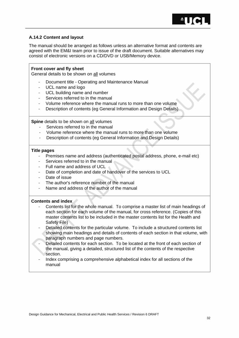
Design Guidance for Mechanical, Electrical and Public Health Services / Revision 6 DRAFT 32
A.14.2 Content and layout
The manual should be arranged as follows unless an alternative format and contents are agreed with the EM&I team prior to issue of the draft document. Suitable alternatives may consist of electronic versions on a CD/DVD or USB/Memory device.
Front cover and fly sheet
General details to be shown on all volumes
- Document title - Operating and Maintenance Manual
- UCL name and logo
- UCL building name and number
- Services referred to in the manual
- Volume reference where the manual runs to more than one volume
- Description of contents (eg General Information and Design Details)
Spine details to be shown on all volumes
- Services referred to in the manual
- Volume reference where the manual runs to more than one volume
- Description of contents (eg General Information and Design Details)
Title pages
- Premises name and address (authenticated postal address, phone, e-mail etc)
- Services referred to in the manual
- Full name and address of UCL
- Date of completion and date of handover of the services to UCL
- Date of issue
- The author's reference number of the manual
- Name and address of the author of the manual
Contents and index
- Contents list for the whole manual. To comprise a master list of main headings of
each section for each volume of the manual, for cross reference. (Copies of this
master contents list to be included in the master contents list for the Health and
Safety File)
- Detailed contents for the particular volume. To include a structured contents list
showing main headings and details of contents of each section in that volume, with
paragraph numbers and page numbers.
- Detailed contents for each section. To be located at the front of each section of
the manual, giving a detailed, structured list of the contents of the respective
section.
- Index comprising a comprehensive alphabetical index for all sections of the
manual
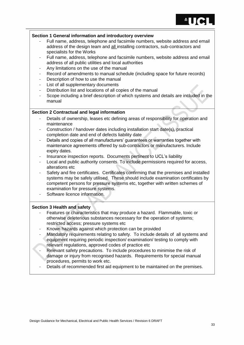
Design Guidance for Mechanical, Electrical and Public Health Services / Revision 6 DRAFT 33
Section 1 General information and introductory overview
- Full name, address, telephone and facsimile numbers, website address and email
address of the design team and all installing contractors, sub-contractors and
specialists for the Works
- Full name, address, telephone and facsimile numbers, website address and email
address of all public utilities and local authorities
- Any limitations on the use of the manual
- Record of amendments to manual schedule (including space for future records)
- Description of how to use the manual
- List of all supplementary documents
- Distribution list and locations of all copies of the manual
- Scope including a brief description of which systems and details are included in the
manual
Section 2 Contractual and legal information
- Details of ownership, leases etc defining areas of responsibility for operation and
maintenance
- Construction / handover dates including installation start date(s), practical
completion date and end of defects liability date
- Details and copies of all manufacturers’ guarantees or warranties together with
maintenance agreements offered by sub-contractors or manufacturers. Include
expiry dates.
- Insurance inspection reports. Documents pertinent to UCL’s liability
- Local and public authority consents. To include permissions required for access,
alterations etc
- Safety and fire certificates. Certificates confirming that the premises and installed
systems may be safely utilised. These should include examination certificates by
competent persons for pressure systems etc, together with written schemes of
examination for pressure systems.
- Software licence information.
Section 3 Health and safety
- Features or characteristics that may produce a hazard. Flammable, toxic or
otherwise deleterious substances necessary for the operation of systems;
restricted access; pressure systems etc
- Known hazards against which protection can be provided
- Mandatory requirements relating to safety. To include details of all systems and
equipment requiring periodic inspection/ examination/ testing to comply with
relevant regulations, approved codes of practice etc
- Relevant safety precautions. To include procedures to minimise the risk of
damage or injury from recognised hazards. Requirements for special manual
procedures, permits to work etc.
- Details of recommended first aid equipment to be maintained on the premises.

Design Guidance for Mechanical, Electrical and Public Health Services / Revision 6 DRAFT 34
Section 4 Emergency information
Contact information for:
- Utility supplier emergency services (gas, water, electricity)
- Provider of emergency call out service
- Installer’s emergency staff
- Security/fire systems
- Location of first aid equipment
- Emergency control locations
- Water main stopcock(s)
- Gas shut –offs
- Electricity isolation points
- Specific systems/plant
Section 5 Description of services and design intent
- A schedule of the floor areas of each of the building zones categorised by
environmental servicing type
- Description of the whole building and intended use
- Design philosophy including all design criteria
- A full description of each of the installed systems and items of equipment. To include
as a minimum a written explanation of the following:
- Scope
- Intended purpose
- Plant and distribution locations; divisions of main zones; etc, cross-referenced
to schematics
- Function
- General design parameters
- Installed capacities
- System capacities (based on commissioning results)
- Restrictions of the systems
- Planned operational efficiency and most economic mode of operation
- Expected service life
- Manufacturers information concerning correct operation

Design Guidance for Mechanical, Electrical and Public Health Services / Revision 6 DRAFT 35
Section 6 Equipment schedules
- System by system schedules of all plant, equipment, valves, distribution boards etc
stating as minimum:
- Component type
- Unique asset number
- System
- Location
- Number off
- Duty and size
- Performance figures
- Manufacturer and supplier
- Manufacturer’s model and/or reference number
- Manufacturer’s serial number and nameplate details
- Original order number for the particular plant/equipment item
- Each item of plant/equipment must have a unique asset number cross-referenced
to the record drawings and schedules.
Section 7 Systems operation
- Descriptions of the operational and control strategies to include:
- Control and operating strategy for each system
- Outline of general operating mode including summer and winter operation
- Start-up and shut down procedures. Description of procedures for whole system
and individual items of plant, from fully off to fully operational, including interlocks
etc.
- Interlocks and inter-dependencies between plant and systems.
- Procedures for emergency shut down and operating procedures for standby plant.
- Means of making safe potentially dangerous plant
- Precautions necessary to overcome known hazards when operating each system,
bringing into operation all standby equipment included in each system
- Instructions on fault finding and emergency in case of plant malfunction or
equipment failure control sequences for all systems installed
- Details of all software provided and procedures for updating and/or modifying
software operating systems and control programs
- Instructions for the creation of control procedure routines and graphic diagrams
where applicable.
Section 8 Energy management
- Energy management strategy to enable energy consumption to be monitored and
controlled.
- Metering philosophy. To include a schedule of the building’s energy supply meters
and sub-meters, indicating for each meter, the fuel type, its location, identification
and description, and instructions on their use.
- Carbon emissions and the comparable performance benchmarks / target figures
for energy consumption and energy costs. (Design assessments to be in
accordance with Building Regulations)
- The measured air permeability of the building
- Forms for recording plant running hours, energy consumption and energy costs.

Design Guidance for Mechanical, Electrical and Public Health Services / Revision 6 DRAFT 36
Section 9 Maintenance
- Maintenance instructions for each item of plant, co-ordinated from manufacturer’s
details and recognised industry guidelines including
- frequency and recommended routine maintenance activities
- guidance on the nature of deterioration and defects
- dismantling and re-assembly
- adjustment , calibration and testing
- special tools needed for maintenance (cross referenced to the particular item)
- test equipment and auxiliary services
- reference to spare parts / replacements
- competence of maintainers
- Programme / frequencies for planned preventive maintenance.
- Comprehensive schedules identifying:
- routine periodic checks on plant / system status and condition.
- periodic verification of accuracy of controls, instruments etc.
- routine visual and physical checks, measurements and certification of
continuing fitness for purpose and safety.
- routine checks / changes to plant / system components / settings to
compensate for wear, operational requirements, experience in use etc so as to
ensure continuing optimum performance.
- Recommended frequencies and procedures for routine lubrication of moving
parts, including generic specification for lubricants.
- Procedures for fault finding and identifying causes of abnormal operation of
plant / equipment.
Section 10 Spares and tools
- Schedule of types of replaceable assemblies, components etc particular to specific
plant.
- Schedule of specialist tools / equipment particular for specific plant and necessary
for undertaking work at height etc.
- Separate parts lists should be provided for each item detailed in the equipment
schedule.
- Schedule of normal consumable items
- Recommended stocking levels
- Schedule of personal protective equipment necessary for operation / maintenance
activities / tasks

Design Guidance for Mechanical, Electrical and Public Health Services / Revision 6 DRAFT 37
Section 11 Drawings
- A schedule of all engineering services record drawings for the Works. The
information to include drawing title, number, source, revision, date, system detail,
file/storage location. The schedule to include space to record future modifications
and dates.
- An A3 / readable size reduced copy of all record drawings together with an index.
- An A3 / readable size reduced copy of all plantroom and switchroom drawings,
schematics and schedules
- Legend for all colour-coded services
- Schematic drawings of each system, indicating principal items of plant, equipment,
valves, etc.
- A schedule of all manufacturers’ drawings for the Works. The information to
include drawing title, number, source, revision, date, system detail, file/storage
location. Schedule to include space to record future modifications and dates.
Section 12 Testing and commissioning data
- Copy of report(s) confirming that the Works were satisfactorily commissioned
signed by a competent person(s)
- Copies of all test certificates, records, commissioning and performance test
records for the Works. All certification should be signed and witnessed.
- Method statements for the testing and commissioning procedures undertaken
including description of equipment used.
- Copies of calibration certificates for all test equipment.
- Schedules of all fixed and variable equipment settings established during
commissioning.
Section 13 Manufacturers’ data
- Schedule of all manufacturers and suppliers indicating company name, address,
telephone and facsimile numbers, email address(es), website address and
equipment unique asset number. (Sorted in company order alphabetically)
- Product (manufacturer’s) data/ literature for all items of equipment and plant
installed. The information to be project specific and include detail drawings,
electric circuit details and operating and maintenance instructions.
Section 14 Materials and substances
- Register of harmful substances. Details of any materials that could be hazardous
to health, used in connection with or otherwise relevant to operational or
maintenance activities.
- COSHH
- Register of recyclable materials
- Methods for safe disposal or destruction of any parts, materials or components.
Provide a data sheet for each material known to constitute a potential hazard, with
detailed procedures for its safe, authorized disposal.
Section 15 Modification information
- Details of allowances made by plant manufacturer or system designer for
modifications
- Provide space in manual to record future modifications.
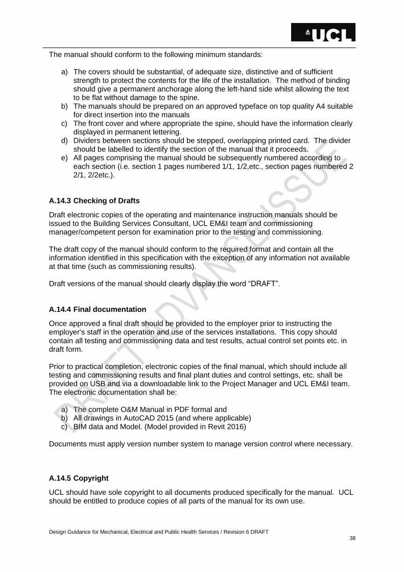
Design Guidance for Mechanical, Electrical and Public Health Services / Revision 6 DRAFT 38
The manual should conform to the following minimum standards:
a) The covers should be substantial, of adequate size, distinctive and of sufficient strength to protect the contents for the life of the installation. The method of binding should give a permanent anchorage along the left-hand side whilst allowing the text to be flat without damage to the spine.
b) The manuals should be prepared on an approved typeface on top quality A4 suitable for direct insertion into the manuals
c) The front cover and where appropriate the spine, should have the information clearly displayed in permanent lettering.
d) Dividers between sections should be stepped, overlapping printed card. The divider should be labelled to identify the section of the manual that it proceeds.
e) All pages comprising the manual should be subsequently numbered according to each section (i.e. section 1 pages numbered 1/1, 1/2,etc., section pages numbered 2 2/1, 2/2etc.).
A.14.3 Checking of Drafts
Draft electronic copies of the operating and maintenance instruction manuals should be issued to the Building Services Consultant, UCL EM&I team and commissioning manager/competent person for examination prior to the testing and commissioning. The draft copy of the manual should conform to the required format and contain all the information identified in this specification with the exception of any information not available at that time (such as commissioning results). Draft versions of the manual should clearly display the word “DRAFT”. A.14.4 Final documentation
Once approved a final draft should be provided to the employer prior to instructing the employer's staff in the operation and use of the services installations. This copy should contain all testing and commissioning data and test results, actual control set points etc. in draft form. Prior to practical completion, electronic copies of the final manual, which should include all testing and commissioning results and final plant duties and control settings, etc. shall be provided on USB and via a downloadable link to the Project Manager and UCL EM&I team. The electronic documentation shall be:
a) The complete O&M Manual in PDF formal and b) All drawings in AutoCAD 2015 (and where applicable) c) BIM data and Model. (Model provided in Revit 2016)
Documents must apply version number system to manage version control where necessary.
A.14.5 Copyright
UCL should have sole copyright to all documents produced specifically for the manual. UCL should be entitled to produce copies of all parts of the manual for its own use.

Design Guidance for Mechanical, Electrical and Public Health Services / Revision 6 DRAFT 39
If the Employer transfers ownership or responsibility of the installations he should be entitled to transfer his copyright of documents included in the manual. Any intellectual property
procured by UCL to be vested within UCL.
A.15 RECORD DRAWINGS
Record drawings of the complete Works should be provided before practical completion. Record drawings of the final "as installed" layouts should be issued in draft form to the Building Services Consultant and UCL EM&I team for examination 4 weeks prior to the testing and commissioning period to allow checking for accuracy. Record drawings should be prepared on the current AutoCAD format and single PDF as agreed with the Building Services Consultant and or UCL representative prior to production of the drawings. All drawings should be suitably layered, with different services on each layer. A detailed list of layers, external references or equivalent (if used) and list of files should be provided. If the drawings were produced from CAD drawings provided by the Building Services Consultant, the same layering system should be used. The drawings should be produced in metric units. Once approved the complete set of record drawings should be revised as necessary to incorporate testing and commissioning data where applicable, and the final set(s) of record drawings and USB format should be handed over at practical completion. Issue at practical completion the complete approved package of record drawings in an electronic format consisting of PDF and DWG. Valve charts, electrical distribution charts in panels and the like, should be issued for examination at agreed dates to allow adequate time for manufacture and installation prior to practical completion. Where portions of the work are to be concealed, draft copies of record drawings should be supplied to the Building Services Consultant before the work is concealed in order to facilitate checking and examination. The record documents should be correlated so that the terminology and the numerical and/or other references used therein are consistent with and similar to those used in the physical identification of component parts of the Works. Each record drawing should show the following information:
a) The name of the contract and, where appropriate, the zone or floor designation. b) Description of drawing, drawing reference and scale. c) Name and address of the contractor and the consulting engineer.
The completed drawings should be signed as record drawings. Each record drawing should be endorsed with the words 'Record Drawing' in the bottom right hand corner adjacent to the title block. Mark up ‘as installed’ details weekly and before any work is hidden from view.
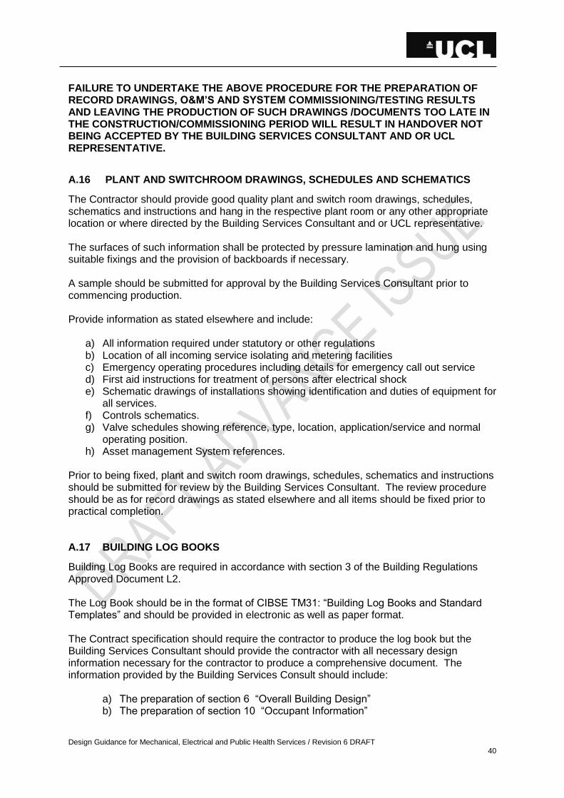
Design Guidance for Mechanical, Electrical and Public Health Services / Revision 6 DRAFT 40
FAILURE TO UNDERTAKE THE ABOVE PROCEDURE FOR THE PREPARATION OF RECORD DRAWINGS, O&M’S AND SYSTEM COMMISSIONING/TESTING RESULTS AND LEAVING THE PRODUCTION OF SUCH DRAWINGS /DOCUMENTS TOO LATE IN THE CONSTRUCTION/COMMISSIONING PERIOD WILL RESULT IN HANDOVER NOT BEING ACCEPTED BY THE BUILDING SERVICES CONSULTANT AND OR UCL REPRESENTATIVE.
A.16 PLANT AND SWITCHROOM DRAWINGS, SCHEDULES AND SCHEMATICS
The Contractor should provide good quality plant and switch room drawings, schedules, schematics and instructions and hang in the respective plant room or any other appropriate location or where directed by the Building Services Consultant and or UCL representative. The surfaces of such information shall be protected by pressure lamination and hung using suitable fixings and the provision of backboards if necessary. A sample should be submitted for approval by the Building Services Consultant prior to commencing production. Provide information as stated elsewhere and include:
a) All information required under statutory or other regulations b) Location of all incoming service isolating and metering facilities c) Emergency operating procedures including details for emergency call out service d) First aid instructions for treatment of persons after electrical shock e) Schematic drawings of installations showing identification and duties of equipment for
all services. f) Controls schematics. g) Valve schedules showing reference, type, location, application/service and normal
operating position. h) Asset management System references.
Prior to being fixed, plant and switch room drawings, schedules, schematics and instructions should be submitted for review by the Building Services Consultant. The review procedure should be as for record drawings as stated elsewhere and all items should be fixed prior to practical completion. A.17 BUILDING LOG BOOKS
Building Log Books are required in accordance with section 3 of the Building Regulations Approved Document L2. The Log Book should be in the format of CIBSE TM31: “Building Log Books and Standard Templates” and should be provided in electronic as well as paper format. The Contract specification should require the contractor to produce the log book but the Building Services Consultant should provide the contractor with all necessary design information necessary for the contractor to produce a comprehensive document. The information provided by the Building Services Consult should include:
a) The preparation of section 6 “Overall Building Design” b) The preparation of section 10 “Occupant Information”

Design Guidance for Mechanical, Electrical and Public Health Services / Revision 6 DRAFT 41
c) The data required for completion of section 11 including the estimated consumption figures for energy.
d) The data required for completion of section 12 including the estimated carbon emissions and design estimates of energy consumption.
Clearly, there are direct links between the building log book and the operating and maintenance manual, record drawings etc. The building log book information is an additional requirement to the responsibilities for the production of record documentation as stated elsewhere. HANDOVER WILL NOT BE RECEIVED IF THE REQUIRED INFORMATION IS NOT PROVIDE WHICH COULD HAVE CONTRACTURAL IMPLICATIONS.
A.18 HANDOVER
This section outlines the requirements and procedures for completion and handover. UCL’s Handover Checklist document must be completed and signed off for each system to the satisfaction of UCL EM&I Team as a pre-requisite to Practical Completion. The contractor must demonstrate the full extent of the contract works, including all variations or part thereof, to the satisfaction of the Building Services Consultant and or UCL representative that:
a) All the contract works are complete. With the exception of minor snags or limited defects as agreed with the Building Services Consultant and or UCL representative that could be reasonably completed within an agreed programme without causing disruption to UCL’s use of the building or part thereof.
b) All spares, keys, tools and other consumables as stated elsewhere have been supplied and handed over to UCL.
c) The instruction of UCL’s staff in the use and correct operation of the installation has been completed satisfactorily. In particular, the demonstration of safety devices and controls.
d) All commissioning and testing completed including the issue of final commissioning reports signed by the UCL approved Commissioning Specialist, Building Services Consultant and or UCL representative.
e) A complete demonstration of the contract works including fully functional operational controls tests undertaken in the presence and to the satisfaction of the Building Services Consultant and or UCL representative.
f) All necessary certification by UCL’s insurers has been completed (if required). g) All approved record documentation including record drawings, operation and
maintenance manuals, etc. is received and approved. h) All information required for the health and safety file is issued to the satisfaction of
the Planning Supervisor. i) All necessary Statutory Authority approvals have been obtained and written
confirmation received. j) Completion and issue of building log book information in accordance with Building
Regulations. SHOULD ADEQUATE RECORD DOCUMENTATION NOT BE AVAILABLE PRACTICAL COMPLETION WILL NOT BE GRANTED. A.19 DEFECTS PERIODS NAMED MATERIALS/SPECIALISTS
During the defects period the contractor should price for addressing any issues arising with all systems covered under the works, including the entire system and not just a part of the system which may have been covered by the works.
Design Guidance for Mechanical, Electrical and Public Health Services / Revision 6 DRAFT 42
The contractor should also price for a 12 month maintenance and servicing period of all works (including entire system) in order to maintain plant and equipment warranties. This will also allow for a 12 month seasonal commissioning programme. Defects arising from failures arising out of improper operation by the Employer or fair wear and tear will not be liable for rectification under contract defects. Carry out all planned preventative maintenance on all Engineering Services works during this period, including:
• Testing in compliance with statutory requirements • Routine maintenance inspections in accordance with the O&M manuals • Replacement of all 'consumables' at no additional expense to this contract • Recording of all maintenance work carried out • Monitoring and recording of all energy consumption through this period • Interpretation of the energy consumption to demonstrate correct operation of the
plant • The requirements of the Building Regulations Approved Document Part L • Seasonal commissioning
The Contractor will prepare and submit records of failures or malfunctions of any part of the works during the defects liability period, together with details of remedial action taken, subsequent re-testing and the results. The Contractor will notify UCL of damage, failures or malfunctions to the works caused by incorrect operation of the installations, vandalism or other actions by a third party. The Contractor will rectify all defects due to materials or workmanship or other faults that occur, including those notified by UCL, during the defects liability period with the minimum of delay and at no additional expense to this contract. The Contractor will inform the Building Services Consultant and or UCL representative in writing when all defects are finally rectified so that an inspection may be carried out prior to the issue of a final certificate. A.20 CARBON, ENERGY, RELIABILITY AND COSTS
For all projects a Carbon Appraisal should be undertaken between design Stages 1 to 3 (GC Works Stage 1) for all plant and equipment whether it is to be retained or replaced as part of the proposed works. This appraisal should align with the UCL Carbon Appraisal Methodology and should broadly consist of the following:
• Energy consumption in use • Energy efficiency in use • Carbon emissions in use • Life cycle analysis • Reliability • Maintenance costs • Controls • Cost of carbon abatement
Design Guidance for Mechanical, Electrical and Public Health Services / Revision 6 DRAFT 43
This appraisal should be undertaken and the resulting recommendations commented and approved by the UCL Project Manager, EM&I and Sustainability teams prior to the project being presented to the Project Review Group. All energy and water consuming plant, equipment and products should be selected in conjunction with the UCL EM&I and Sustainability teams and in line with the approved technology lists and BRE Green Guide. A.21 WORKING WITH ASBESTOS
On all projects the aim is for the total removal of all and not the encapsulation of asbestos identified and should therefore form part of the works if identified. Please refer to the following UCL guidance documents for further information. http://www.ucl.ac.uk/estates/asbestos-register
A.22 NAMED MATERIALS/SPECIALISTS
Where particular manufacturers/specialist suppliers are mentioned in this document, this is to illustrate items/services that are proven to meet UCL requirements and to assist in minimizing stockholding of spares and specialist training of staff. The Building Services Consultant should ensure the suitability of such materials or specialists for the particular scheme and remain responsible for their integration into the design. The Building Services Consultant is at liberty to consider alternatives and to establish whether such alternatives are acceptable to UCL, particularly if the designer has reservations about the use of such materials or specialists. The Building Services Consultant should obtain approval in writing for any alternatives. Similar provision should be included in Building Services Consultant specifications used for tendering purposes to clarify that such materials or specialists are not nominated and their performance under the contract remains the responsibility of the contractor. Passive Fire protection relating to the integrity of fire compartments, are being actively managed at UCL, to comply with obligations under the Regulatory Reform (Fire Safety) order. The Building Services Consultant should ensure compliance with the requirements set out in UCL Fire Technical Note No. 066. A.23 OTHER APPLICABLE UCL TECHNICAL DOCUMENTATION
Detailed technical documentation should be consulted where these apply and in the absence of specific information for particular systems being covered by this document. In particular: http://www.ucl.ac.uk/estates
• Design and Refurbishment of Radiation Laboratories (LR 16) • Relevant “FIRE SAFETY ADVICE” documents (downloadable from
http://www.ucl.ac.uk/efd/efm_www/maintenance/fire/) • UCL’s Metering Specification • UCL’s Specification for Structured Cabling System (from ISD Nigel Hayward) • UCL’s Turnstile Integration Specification Guidance Document.
Design Guidance for Mechanical, Electrical and Public Health Services / Revision 6 DRAFT 44
A.24 HEFCE FUNDING
The Higher Education Funding Council for England (HEFCE) guidance has declared that performance in reducing carbon emissions will influence capital allocations from 2011. HEFCE has commissioned research that will recommend targets and help develop a strategy for reducing emissions. In the meantime feasibility studies and cost plans for new build and substantial refurbishment projects should be required to consider carbon reduction proposals to ensure that applications for funding demonstrate UCL’s commitment to reducing its carbon footprint. New Construction The design team for new construction projects should ensure that they comply with current Building Regulation Part L2A and should ensure that they achieve the Target CO2 Emission Rate (TER) as calculated using an approved calculation tool. In addition targets determined by current legislation (planning guides etc) should also be complied with. The Building Services Consultant should also investigate if further reductions in CO2 emission are achievable. A feasibility report should be prepared advising on potential energy and CO2 emission reduction that can be achieved within reasonable financial constraints. The Building Services Consultant should not only investigate Low or Zero Carbon energy sources but must also show that other factors have been considered. These include items such as reducing demand and influencing the built form and envelope. Refurbishments of Existing Buildings All refurbishments of existing Buildings should comply with the current Building Regulation Part L2B and where applicable Part L2A. Designers for refurbishment projects should apply all reasonable measures to reduce CO2 emission and should refer to Energy Log Book and Display Energy Certificates of the existing Building to advise on potential energy and CO2 emission reductions. A feasibility report should be prepared advising on potential energy and CO2 emission reduction that can be achieved within reasonable financial constraints. A.25 HEALTH AND SAFETY
Comply with the requirements of all relevant health and safety legislation and regulations including the Construction (Design & Management) Regulations (CDM) 2007. The Building Services Consultant should be responsible for incorporating Safety in their Designs. As part of each stage gate approval process, Residual Risk Assessments should be provided.

ELECTRICAL SERVICES
B.1 ELECTRICAL DESIGN CRITERIA
B.1.1 HV Electrical System
High voltage networks and systems do not normally form part of the work remit of installations conducted at UCL. An HV ring exists on UCL’s main campus site as part of a CHP system owned and operated UCL. The Authorised Person responsible for this system is Rod Green, who must be engaged on all proposed works affecting this system.
Telephone: 020 7679 7855 Email: [email protected]
Any electrical alterations or upgrades that require connection to a substation / Main switchroom are to be carried out in accordance with the Electricity Safety Quality and Continuity Regulations (ESQCR): (latest amendment), upon getting prior approval for this arrangement from the UCL EM&I team. In the rare cases where HV equipment and switchgear is to be incorporated in the UCL works, the design should comply with all relevant standards. The design should include the facility to isolate for either maintenance or an emergency situation. The HV switch should earth the transformer and must be located on the part of the network that falls under the responsibility of UCL. Consideration must be given at the design stage to limit over voltage when the transformer is partly loaded. The high voltage system should be designed to supply low voltage (230/400V) within the upper and lower limits as laid down in BSEN 5160:2010. All high voltage installation should incorporate an emergency power off button to enable the isolation of the high voltage system in the event of emergency without the attendance of a high voltage senior authorised person. All high voltage installation should be securely segregated from other plant areas, to restrict access to authorised personnel only. Where applicable the high voltage and low voltage protection system should be commissioned together by a specialist protection engineer to ensure the correct discrimination achieved in a fault condition. B.1.2 LV Electrical Supplies
In accordance with the Electricity Safety Quality and Continuity (ESQC) (Amendment) Regulations, the designer, in so far as it is necessary, is required to liaise with the parties outlined within the said document, in relation to LV supply requirements. Consultation to be carried out with the following when negotiating a new supply connection:
1. The Supply Authority 2. The Metering company 3. UCL’s Energy Manager 4. UCL’s Property Manager {for lease agreement matters}
The Building Services Consultant should investigate and design for:
Design Guidance for Mechanical, Electrical and Public Health Services / Revision 6 DRAFT 46
• Installed load for an existing facility (where applicable) • Proposed additional loads • Nature and characteristic of proposed loads • The capabilities of the existing electrical infrastructure • The completeness and security of the existing protective earthing system. • The load balancing of the existing system discrimination assessment on existing and
proposed protective devices on the complete system.
Specific Criteria
Voltage 400V, 3phase 50Hz / 230V, 1phase 50Hz
Volt drop tolerances (i) Supplied directly from public LV
distribution. (ii) Supplied from private LV supply
(with condition outlined in BS7671)
Lighting Other uses
3% 5%
6% 8%
Power Factor Correction (pf) >.95
Total Harmonic Distortion 5% @ 400V and 4% @ 6.6,11 and 20KV.
Individual odd Harmonic Distortion (max) 4%@400V and 3% @ 6.6,11 and 20KV.
Individual even Harmonic Distortion (max) 1.6%@400V and 1.5% @ 6.6,11 and 20KV.
Earth impedance at earth electrode < 1 ohm
B.1.3 Electricity Generating Plant
The private generation associated with the CHP system is for Base load support and has no allowance for exporting to the Grid. The system will not operate in island mode in the event of the imported Grid supply being totally lost. Generating plant as standby generation should always be considered where essential services have been identified in a project proposal / brief. Stand-by electrical generators should comply with BS 5514 and all designs parameters should be agreed with UCL EM&I team prior to completion of concept design Stage 3. The generator should comprise diesel/gas engines (UCL prefer Diesel Engines). The system should be fully automatic and should function on a main fail basis. The main LV switchpanel should incorporate necessary mechanical and electrical interlock change over controls. Consideration should be given to the location of fuel fill points and storage. Sufficient fuel storage to run the generator at full load for a period of minimum 12 hours should be provided. Fuel storage should be supplied with a meter, with capability for monitoring through the Building Management System, The standby generator system should include appropriate weather proof acoustic enclosure (for external location), controls, silenced exhaust systems (max 75 dBA @ 1metre), electrical starting system and auxiliary power supplies.

Design Guidance for Mechanical, Electrical and Public Health Services / Revision 6 DRAFT 47
Notwithstanding the financial boundaries, due consideration should be given to other means of achieving standby or alternative supply arrangement, and a cost projection plus life cycle cost analysis carried out and submitted to the Project manager for consideration. For embedded private generation systems, proposed to work in parallel with the National Grid supply, these should conform to Engineering Recommendations P 28, G 53 and G 59 for power quality and safety.
B.1.4 General Lighting Systems
Lighting should be provided that is suitable for the environment being served and anticipated tasks. Fundamental Requirements:
• Design to CIBSE Lighting Guide recommendations • Equipment specified must be manufactured to British Standards. • Reliability and efficiency of operations essential • System must be flexible for alterations and development.
Energy efficient designs are expected as a minimum, to be achieved by a dual approach in selecting efficient components and implementing efficient control measures. B.1.5 Emergency Lighting Systems
• Designed to BS 5266 and BSEN 62034 recommendations. • Designed and installed to achieve BAFE accreditation. • In accordance with UCL Standard Operating Procedure:
Emergency Lighting : Planned Preventative Maintenance Document EM&I C015 • In accordance with UCL Fire Safety Technical Guide,
TN 020 Emergency Lighting – UCL General Design Guidance. • In accordance with UCL Fire Safety Technical Guide,
TN 059 Specialist Fire Alarm / Emergency Lighting requirements for BSU’s (where appropriate)
• In accordance with UCL Document : 140409 Emergency Lighting • Risk assessment required to establish full coverage. • Luminaires Manufactured to BSEN 60598 Part 2.22 • Maintained luminaire conversions to be to ICEL 1004 by ICEL registered companies • Accessibility to luminaires must be considered particularly in relation to working
height stipulations from the HSE. • Emergency luminaire must be aesthetically pleasing with consistent symmetrical
design layout that effectively illuminates the necessary areas. • Emergency lighting system should be fully automatic for testing, monitoring and
control. •
Specific Criteria
Illumination levels on escape routes 1 lux minimum. Uniformity, Maximum to Minimum illuminance ratio to be 40:1.
Illumination levels on staircases 1 lux minimum. Uniformity, Maximum to Minimum illuminance ratio to be 40:1

Design Guidance for Mechanical, Electrical and Public Health Services / Revision 6 DRAFT 48
Illumination levels open areas 1 lux minimum. Uniformity, Maximum to Minimum illuminance ratio to be 40:1
Illumination levels high risk areas 10% of General lighting Illuminance or Minimum 15 Lux, Uniformity <10:1
Illumination levels Lift Motor Rooms 10% of General lighting Illuminance or Minimum 15 Lux, Uniformity <10:1. With emergency Task Illumination directly at each winding
Identified DDA areas 10% of General Lighting Illuminance or Minimum 15 Lux, Uniformity <10:1
Duration of battery 3 hours minimum
B.1.6 Power Systems
• System design should be adequate plus allow 30% spare capacity • System to be flexible to enable additions / omissions without major disruptions to
others. • Include measures to protect users and occupants from the possibilities of direct and
indirect shock. • Selected products to have proven reliability record. • Proposed installation method to suit environmental requirements • Where product selection and designs are stipulated as the responsibility of the
contractor, stringent parameters must be detailed by the designer to achieve best quality.
Containment systems associated with final circuit serving small power supplied should be suitable, durable and allowing future capacity for the proposed environment. Measures to mitigate EMF effects should be implemented in design with consideration of the proposed equipment to be installed.
B.1.7 Fire Alarms, Detection and Suppression Systems
• System must conform to BS 5839 • Stipulation of Open Protocol system including panel software is essential. See UCL’s
Fire Safety Technical Guides • Design should utilise products that should facilitate reliable operation and immunity to
unwanted alarms. • Implement UCL’s general policy of protection of Life. • Equipment manufacturers to be selected from approved list and registered with the
Loss Prevention Certification board. • UCL Fire Safety Technical Notes & Mandatory Instructions, please follow the
hyperlink for details: http: http://www.ucl.ac.uk/estates/maintenance/fire/documents/ • In accordance with UCL Fire Safety Technical Note,
TN 059 Specialist Fire Alarm / Emergency Lighting requirements for BSU’s (not available for download due to sensitive information)
The Building Services Consultant should consult in with, Local councils, London Fire & Civil Defence Authority, UCL‘s Fire Safety Technical Guide, and liaise with user departments
Design Guidance for Mechanical, Electrical and Public Health Services / Revision 6 DRAFT 49
where applicable when developing the design and conducting the necessary risk assessment. Fire risk assessment can also be required by UCL’s property insurers as part of the strategy to safeguard valuable contents or parts of buildings. UCL’s insurer’s requirements should be obtained through the project manager. In accordance with the Regulator Reform (Fire Safety) Order (-2005) the complete fire safety strategy for the building should be considered by the designer in all cases and all necessary works including such aspects as fire stopping and creating fire compartments should be allowed for. Where necessary works in this regard has been identified during the process of design, but is outside of the scope of the project remit, these should be brought to the attention of the UCL Fire/Safety Officer. B.1.8 Mechanical Wiring
UCL’s general policy is for the mechanical interconnecting and MCC wiring to be allowed for in mechanical engineering contract works. Primary electrical supplies to mechanical plant / equipment are to be part of the electrical engineering designs for installation by the electrical contractor. The Building Services Consultant is required to carry out necessary liaising with the Mechanical and Electrical Building Services Consultant associated with any given project, to establish the full extent and specific requirements to be allowed as part of the electrical tender package. B.1.9 Lightning Protection System
Lightning protection design should be in accordance with BS EN 62305 and incorporating all necessary bonding of exposed conductive parts and other systems as detailed therein. The designer is required to assess the necessity for lightning protection in relation to the surrounding and probability of lightning strike hitting the structure, with a bias towards safety at all times. Electronic Surge Protection (ESP) system should be provided as per the risk assessment. Consideration to be given to the aesthetic impact, reaction to dissimilar metals and practicality of accessing testing points to be paramount in the application of design. Where alteration to and existing system is proposed the suitable clamping and coupling accessories should be used and the system re-tested to confirm low impedance readings. Lightning protection system components to be in accordance with BS EN 50164. Facilities for periodic testing and inspection should be allowed for the design. B.1.10 Earthing Systems
Earthing and bonding of systems should be designed and installed to conform with the recommendation of BS 7671(latest amendment), BS 7430, BSEN 50310, and electricity supply authority requirements. All designs should employ as “best practice” segregation of sections of earthing system to achieve a “clean” and “dirty” system for electronic and motor loads respectively.

Design Guidance for Mechanical, Electrical and Public Health Services / Revision 6 DRAFT 50
Allow for bonding all exposed conductive parts of the electrical installation and all such extraneous conductive parts associated with the structure as necessary. The designer shall assess any specialist earthing requirements that might be associated with research facilities and implement “Functional Earthing” in accordance with manufacturer’s guidance and to the specific impedance levels.

Design Guidance for Mechanical, Electrical and Public Health Services / Revision 6 DRAFT 51
B.2 GENERAL REQUIREMENTS
B.2.1 Decommissioning of Systems (applicable to existing buildings only)
The Building Services Consultant should include specific clauses in the relevant sections of their specifications and if possible indicate on drawing decommissioning necessary for the following services.
• Fire Alarms and Detection Systems • Emergency Lighting Systems • UCL’s Energy / Power monitoring Networked meters system
The building services consultant should ensure that UCL has the opportunity to retain any redundant equipment (for use elsewhere) prior to decommissioning, Fire Alarms and Detection Systems These should be decommissioned by UCL’s termed Maintenance contractor for Fire Alarms systems. As outlined in UCL’s Fire Safety Technical Guides decommissioning should involve the conversion of the system to construction site requirements by replacing smoke detectors with heat detectors where these exist. Whilst liaising with UCL’s Fire Officer the Building Services Consultant should conduct discussions on decommissioning works. The replacement of smoke detector with heat detectors is only considered part of the requirement necessary for mitigating the possibilities of false alarms due to construction site pollutants whilst providing some fire coverage to the site area. Methods of restricting such pollutants from circulating to other parts of a building still in occupation should be addressed at design stage with the Electrical Design Engineer taking the lead on raising this at design meetings. Emergency Lighting Systems Existing addressable Emergency systems must be decommissioned by UCL’s termed Maintenance contactors employed under the contract works. Where existing central battery systems exist, critical elements such as the cabling and battery system should not be decommissioned in an occupied building until replacement systems or alternative connection measures are in place. For self contained emergency luminaires with traditional local controlled test key switches no special allowance for decommissioning required. For self contained emergency luminaries complete with addressable testing modules and connected to a central addressable emergency panel, decommissioning should be carried out by the manufacturer or any termed contractor managing the system. The Building Services Consultant should familiarise themselves with existing systems and incorporate clause(s) within the specification for the decommissioning works ensuring this does not compromise coverage for the occupied areas outside of the contract site. UCL’s Electricity monitoring Networked (EMON) meters system

Design Guidance for Mechanical, Electrical and Public Health Services / Revision 6 DRAFT 52
As a dual function of meeting Building Regulation part L and enabling better power / energy management at UCL, intelligent electricity, heat, gas and water check meters are installed linked back to a head-end Server managed by EM&I and or the BMS system, via a VLAN data network. Decommissioning of any part of this network should be discussed and agreed with UCL’s Electrical Team Leader and UCL’s Energy Manager at design stage. NO PART OF THIS SYSTEM SHOULD BE DISCONNECTED, ALTERED, ADAPTED OR REMOVED WITHOUT APPROVAL FROM THE E.T.L. AND THE ENERGY MANAGER Equipment becoming available as result of a decommissioning exercise should be offered back to the UCL EM&I team for taking back into storage in the first instance, where a decision will be made on the course of action. The Building Services Consultant should ensure the requirement to completely strip out and remove from site all redundant equipment and wiring, or where this is not possible, clearly define the extent of removal required. The Building Services Consultant will also be responsible for verifying this has been carried out by the contractor in a safe manner, and to UCL’s satisfaction. Waste Disposal The Contract documents should stipulate that contractors should comply with the Site Waste Management Plan (SWMP) Regulations 2008. They will be required to keep this up-to-date and provide detailed breakdown of tonnage disposal of all waste from site and the percentage that has been recycled/re-used. In particular WEEE Directive recycling should be applied as much as possible. B.2.2 HV Systems
Close liaison with the supply Authority is important to determining the correct equipment and design configuration of any works associated with HV systems. In the absence of specific requirements the following guidelines should be implemented as best practice designs:
• Selected products should be suitable for the intended use and environmental conditions likely to be encountered.
• Substations to be as conventional brick structure as Glass Reinforced Plastic housing as detailed in UKPN Energy’s “Building Standard for Secondary Substations and Switchrooms”
• Internal dimensions and ventilation allowances should be sufficient for effective ambient temperature control within the substation, without the need for forced ventilation.
• Transformers should be as energy efficient as available. • The option of Cast resin Transformers should be investigated as an alternative to
standard Oil type transformers where these are a practical alternative due to weight and other factors.
• “Right of access” is required for all equipment and cabling associated with the supply authorities HV supply, and as such this should be allowed within any design.
• Levels of Electromagnet Interference are to be within the guidelines dictated by the National Radiological Board now covered under the Health Protection Agency.

Design Guidance for Mechanical, Electrical and Public Health Services / Revision 6 DRAFT 53
B.2.3 Electrical Substations
To be designed in accordance with the guidance issued by Distributed Network Operator. UK Power Networks Metropolitan House Darks Lane Potters Bar EN6 1AG Or any other such Operator. B.2.4 LV Switchgear
All switchgear is specified for Low Voltage installation to comply with all relevant standards. Switchgear should be complete and whilst designed to maximise the circulation of air for natural ventilation measures should be taken to minimise possible contamination and egress of dust, particles, damp and vermin. Hence IP rating should be specified in relation to the environmental conditions likely to prevail. Switchboards / switchpanels are to be ASTA BEAB or KEMA tested and certified with regards to the protective devices and systems employed. Instrumentation should be in accordance with IEC 51 (BS 89) with controls conforming to BS EN 60947-4-1 and BS6231. All switchboards, control panels, Motor Control Centres, etc, to be designed / specified complete with all the necessary interconnections and switches on busbars, cables, connectors to modularise these systems such that their removal from the complete installation can be carried out with minimal disruption and continued operation of the overall system. All switchboard should be provided with minimum 20% spare capacity for future expansion. This will include a combination of spare breaker and space. Complete earthing system to be incorporated on all designs with earthing points clearly identified, testing points and full earth bonding incorporated in accordance with BS 7671. (See Earthing section) All switch panel construction should be as Form 4 Type 2 or 6 with minimum short circuit rating of 50KA for 1 second, unless otherwise specified. (to be determined by the UCL EM&I team) and provided by one of the following preferred manufacturer:
1) AF. Switchgear Ltd 2) Carville Switchgear Ltd 3) Schneider Electric Ltd
Existing buildings: Where modular switchboard options are not suitable, bespoke solutions must be designed particularly where space limitations and access complexities dictates. New Buildings: Standard or bespoke panel solutions are acceptable as long as the full operational and safety criteria are met. The Building Services Consultant however should ensure that sufficient space is allowed by the Architect to facilitate effective equipment
Design Guidance for Mechanical, Electrical and Public Health Services / Revision 6 DRAFT 54
operation and maintenance. Ventilation should be free air assisted by the overall volume and structural design of switchrooms. In meeting the requirements of Building regulations part L2A & B, facilities to provide metering should be incorporated within the panel design as necessary. In addition, all other outgoing ways should be equipped with CT’s, “CT shorts” and voltage connection points to enable the installation of future meters as and when necessary. Meters, associated equipment and wiring should be in accordance with UCL’s requirements as detailed elsewhere. Alternatively distribution boards or panel boards utilising Merlin Gerin NSX MCCB breakers, incorporating metering function, and should have network cabling connected to all outgoing cubicle compartments including spare cubicles. Switchpanel requirement: Paint finish / Casework - powder coated finish. Fire Systems supplies Cubicles - door(s) colour Poppy Red Factory Plinth - As Panel Colour or Black Fault Level Withstand - 50kA for 1 sec (unless otherwise specified). Integrity - BS EN 60529 IP31 Form of Separation - BS EN 60439-1 Form 4 type 2 or 6 Construction Body - 2mm (minimum) Zintec mild steel Doors / Covers - 5mm (minimum) Zintec mild Steel Glandplates - 4mm Aluminium Access - Front and Rear Cable Entry - Top and / or Bottom Components: ACBs - Merlin Gerin, or ABB. MCCBs - Merlin Gerin, or ABB Multimeters – Schneider ION meters (commissioned by Schneider EMS) TSS - Furse or similar C/Ts - Rayleigh / Crompton or (as approved by meter supplier) - Power Factor Correction - Eaton JSP or as Panel Manufacturer Ref C/T - Moriarty or similar Estimated weight to be suitable for floor construction. Busbar Phase Identification In Brown (L1), Black (L2) Grey (L3) and Blue (N)(Neutral) Neutral conductors – Full size or Double Neutral as harmonic assessment requires Insulation of Live Parts – By Barriers or Enclosure Busbar Size– To a capacity of at least 20% greater than Design Current Busbar Supports – sufficient regularity to eliminate mains humming. Type Tests – The following Certificates are required Temperature rise limits Dielectric properties Short-circuit strength Continuity of protective circuit Clearance and creepage distance Mechanical operation Degree of protection Short circuit withstand strength

Design Guidance for Mechanical, Electrical and Public Health Services / Revision 6 DRAFT 55
Factory and on site test to be witnessed by the Building Services Consultant and UCL EM&I team and offer made to the UCL Project manager for a UCL representative to be present. Current Transformers should be installed to meter manufacturer’s recommendations on all incoming and outgoing ways wired to suitable terminal units with CT short links mounted on DIN rail, for both meters specified as part of the panel manufacture as well as for future additional meters. Where necessary CT’s should be installed on Neutral bars to afford full Power quality monitoring functionality of meters that so requires this. Electricity meters should be in accordance with UCL meter specification for UCL networked meters. Allowance should be made for the commissioning of the meter systems, constituting of a factory inspection and an on-site commissioning carried out by Schneider Electric EMS. Meter types and network arrangement to be approved by UCL EM&I team. Panel should allow for the connection of the meters network back to UCL’s VLAN intranet via RJ45 port and without the risk of exposure to live conductive parts after final install. The full commissioning of system must include the works required on the head-end Server. Alternative supply terminal connections should be included in switchpanel design, down stream of the supply authority’s electricity meter position and including means of isolation to facilitate termination of generator or other secondary source. Controls for bringing this online should be through Castell interlocks (mechanically) and changeover switches. Panels should be designed to enable, in as far as possible, the ability to conduct thermal imaging surveys in a safe manner. A brief thermal image survey report should be carried out as part of the final submission once system is in operation with end user loads established.
Device Type Breaking capacity Number of Poles Comments
ACB 50kA 4 Discrimination calc’s and settings by designer
MCCB 18kA min 3 & 4 Discrimination calc’s and settings by designer
MCB 10kA min 1, 2, & 3 Discrimination calculations by designer
Fuse As fuse rating N/A Discrimination calculations by designer
The Building Services Consultant should ensure devices selected are sufficient to withstand a potential short circuit fault at the points of implementation. Outgoing protective devices should be plug-in type where this is possible. All outgoing circuit should be labelled as described in section B.2.33

Design Guidance for Mechanical, Electrical and Public Health Services / Revision 6 DRAFT 56
B.2.5 Residual Current Devices
All circuits to be fitted with RCD / RCBO protection in accordance with BS7671 17th Edition, but for the exception of circuits with loads or other devices likely to cause unwanted tripping due to high leakage currents generated as part of their normal operation. Fridges, Freezers and computers should be considered as such loads / devices. The designer must assess earth fault loop impedance in ensuring RCD / RCBO operation within the respective reaction time. Permanent labels should be provided to the socket outlets which are not protected by RCD Devices should generally be incorporated within distribution boards as RCBO units or alternatively fitted local to the area being served, if the nature of use means tripping is likely and resetting of devices can be managed by technical staff within the client department. “S” – selective devices should be employed only where this is required to provide discrimination with another RCD device downstream. The Building Services Consultant should be responsible for ensuring at all time the ADS (automatic disconnection of supply) times are achieved in accordance with the wiring regulations BS7671 whilst employing RCBO and MCB/RCD systems. B.2.6 Fuses and Disconnecting Links
Fuse links should be high breaking capacity conforming to BS 88, unless otherwise specified. Fuse bridges and boxes should be of glazed porcelain/thermoplastic or other approved non-hygroscopic insulant construction. Disconnecting links being of hard-drawn high conductivity copper B.2.7 Distribution Boards
All distribution boards to comply with BS 5486 and BS EN 60439 generally as surface mounted units or where proposed as flush mounted, designed with adequate and suitable access for maintenance and rewiring. All distribution boards should be provided with key locks. Allowance to be made for additional earth bar to be fitted in all boards to facilitate meeting the earthing requirements of BS 7671 section 543, and / or any clean earth connections necessary. Electronic Surge protection Device should be provided where necessary. Neutral and Earth bars must have provision for the same number of conductors as outgoing ways. Fuse boards must be complete with cartridge fuse links of the correct rating. MCB Distribution boards and MCCB panel boards to be appropriately sized and should be capable of have additional protection devices fitted without the need to disconnect the feed. When selecting such equipment the designer should obtain confirmation from manufacturers of their policy to support these products for a minimum of 10 years. Connections to the neutral bar are to be made in such a way that they correspond to the relevant phase.

Design Guidance for Mechanical, Electrical and Public Health Services / Revision 6 DRAFT 57
All necessary barriers to be fitted to enable safe working and prevent the possibility of direct contact. UCL’s preference is for Schneider-Electric Merlin Gerin distribution boards where new is being specified. B.2.8 Busbar Systems
Should be manufactured from solid drawn or laminated copper representing the 3 phase, neutral supply and earth to comply with BS EN 60439-2. Neutral conductor to be (minimum) full size as phase conductor, and where significant harmonics is likely to be generated on the system double size neutrals to be allowed. Tap-off busbar systems live copper conductors must be fully enclosed and suitable rated for the prospected earth fault associated with that part of the system, assessing the following conditions:
1) short-time withstand rating 2) peak current withstand rating 3) Conditional short-circuit rating when protected by a short-circuit protective device.
UCL’s standardisation requires busbar systems where new is being specified. The Building Services Consultant should be reminded of the need to assess volt drop on busbar systems, obtaining resistance and impedance values from the manufacturer as necessary. B.2.9 Uninterruptable Power Supply units
UPS should only be installed where an uninterruptable power supply is absolutely essential. This should be approved by UCL’s Environmental Sustainability team prior to design commencement. System to comply with BS EN 50091-1, BS EN 50091-2, BS EN 62040 and BS EN 62040-3. Static and Rotary UPS installation should be assessed on the merits for the installation proposed. Essential requirements:
• EMC Suppression to IEC 1000 limits. • Output voltages 380V – 415V, 3 phase at 50 HZ • Frequency tolerance +1 % • Power factor correction (min) 0.9 • Incorporation of full bypass system to enable extensive maintenance. • Remote monitoring should be available as an option. • UPS should be on-line device with 12 pulse rectifier as a minimum standard, but
needs to be confirmed with the UCL EM&I team during design stage. UCL’s preferred supplier of UPS:

Design Guidance for Mechanical, Electrical and Public Health Services / Revision 6 DRAFT 58
1) Chloride 2) MGE 3) APC Schneider 4) Caterpillar / Standby Power Ltd 5) Piller (UK) Ltd
B.2.10 Transient Surge Suppression, Harmonic Conditioners and Power Factor units
Consideration should be given to the likelihood and extent of electronic noise and their effects on the system as an incumbent part of achieving an EMC compatible system. The Building Services Consultant should consider the full building application of suppression systems where full rewiring of an existing buildings infrastructure is proposed or on new building projects. Power factor correction units to be allowed on all new supplies. Power Factor units should be suitably sized and automatically switched in banks to ensure a minimum building power factor of 0.97 with all the services operational. Measures to mitigate the effects of harmonic currents to be implemented particularly in buildings employing large amounts of harmonic generating loads whilst conducting business critical operations. B.2.11 Electricity Metering
Electricity Utility supply meters (HV/LV) should be installed to the specification of the metering company. The Building Services Consultant should make all the necessary arrangements with the respective meter providers for any installation requiring a new connection from the supply authority. It is preferential to meter lighting and power separately. At the design stage 1 comprehensive meter strategy should be provided by the Building Services Consultant and approved by UCL Energy Manager. Information on any existing metering system can be obtained from the UCL EM&I team. Allowance should also be made for a telephone line and CAT box, to be installed for remote monitoring of this system, to the particular stipulation of the metering company, and UCL’s energy section respectively. UCL in meeting the requirements of Building Regulation part L2A is progressively installing check meters on their EMON (monitoring system) that are networked to provide power quality and energy consumption information. The designer should contact the UCL EM&I team for detailed information on these meters and this system. The full specification of this system should be included in designs where check metering is to be installed. Allowance should be made for commissioning of these meters to be carried out by C-Matic Systems Ltd. B.2.12 Earthing Systems
Safety Earthing:

Design Guidance for Mechanical, Electrical and Public Health Services / Revision 6 DRAFT 59
In accordance with BS 7671, providing where necessary a low ohmic impedance earth rod and full bonding of potential extraneous conductive materials and structure. Lightning Protection Earthing: In accordance with BS EN 62305, providing protection of occupants, prevention of direct damage and fire, flashover or explosion due to direct lightning strike. System to also aid the dissipation of short circuit currents. Equipment protection and functionality Earthing: In accordance with BS 7671, BS EN 61000, BS EN 50310 and equipment manufacturers recommendations. Earthing system must protect electronics by providing a low impedance path to interconnect equipment. Proper cable routing, zoning and shielding are important aspects of the design and have a significant purpose in preventing possible disturbance from electromagnetic and radio frequency interference. Expert advice on earthing solutions to be obtained where necessary. B.2.13 Power Services
Accessories for small power services should be to BS 1363 and all other relevant standards. Finish for wiring accessories should be as specified by architect and approved by UCL Wiring of power systems as ring and radial are to be specified with suitably sized cables allowing for containment systems to maintain the physical and magnetic integrity of the circuits. RCD’s to be allowed on socket outlet rings as stipulated elsewhere. All ring socket outlets to be provide with dual earthing arrangement and wired in accordance with BS 7671 requirements for high protective conductor currents 543.7.Cleaners sockets should be provided at every 15meter interval for cleaning purpose. The designer is required to select items of equipment suitable for the environment and purposed usage or outline stringent stipulations where the selection of equipment is included as part of the contractor responsibility. Circuit protection devices to be as new unless otherwise stipulated with full discrimination calculations carried out and where cascading protection has been designed in, settings associated with adjustable devices to be clearly stated. Variable speed motor drives for HVAC equipment’s should be installed, where possible adjacent to the motor which it controls. Where this is not possible consideration should be given to the EMC screening of the wiring and isolator. Allow EMI &RF filtering as close to the point of connections for equipment to be protected where this is specified or deemed necessary. UCL preferred supplier of accessories relating to power services is MK Electric or Legrand. For higher rated ingress protected plug and socket disconnector unit Marechal Electrics devices are the preferred option. Alternative power supplies in the form of battery back-up, UPS’s, standby Generators, or alternative source from a different substation or H.V. ring to be given full consideration as design warrants.
Design Guidance for Mechanical, Electrical and Public Health Services / Revision 6 DRAFT 60
Additionally the Building Services Consultant should assess the possibilities for using smaller UPS units, which would be installed as client managed items, local to the equipment or system being served. Where necessary designer should advise on the benefits of such as system to users work process for the UCL EM&I team and the UCL Project Manager to make and informed decision at design stage. All circuits, both sub-mains and final, should be complete with separate CPC.
B.2.14 Wiring Systems
Wiring should be of an approved manufacture, continuous and providing sufficient support, spare capacity, screening and earthing where necessary. Approved systems:
1) Conduit: 2) Trunking: 3) Cable tray, basket, ladder
UCL prefers metal containment systems which are more durable, can be used as an earth path and provides better screening properties if installed correctly. Under no circumstances should cable be allowed to rest on any suspended ceiling grid/tiles. All surface run containment should be fixed to the ceiling using appropriate clips/ support at every 300mm interval or as recommend by the manufacture. Domestic standard “twin and earth” cable is not acceptable for UCL installations.
B.2.15 LV Cable Identification
Alphanumeric labels should be fitted on conductors at all points of termination as black text printed on white background indicating (L1), (L2), (L3) and (N) stick on labels. For single phase supplies the phase conductor should be labelled L1 or L2 or L3 and not just L as Table 51 of BS7671. Where existing cables are to be re-terminated on a newly installed system, the individual cores should be sleeved with the new colours, preferably heat shrinked onto the cable at the termination points, and Alphanumeric labels applied., Label sizes and text heights to be a sufficient to be able to identify cables without exposure to live parts. All cables sheath should be Low Smoke Zero Halogen (LS0H) and should be BASEC approved and this should be clearly identified on the cable drums. All other labelling in accordance with BS7671 should be applied as necessary.

Design Guidance for Mechanical, Electrical and Public Health Services / Revision 6 DRAFT 61
B.2.16 Cable Types & Colours
Apart from the colour identifications outlined above the following colour assignments should apply to all installations within the college.
B.2.17 Lighting
Lighting luminaires to conform to BS EN 60598. CIBSE lighting Guide recommendations should be employed for obtaining a good standard of design. Designs should also conform as far as they are applicable to the following Guidance and Limitations:
1) Building Regulations (Part L2A) 2) BRE (BREEAM)/SKA 3) SLL (Society of Light and Lighting) CIBSE Code for Lighting. 4) BS EN 12464-1 5) The Equality Act.
The Building Services Consultant should be aware of imminent industrial changes to the recommendations and standards and where prudent allow for such changes within their design. Where possible task lighting to be considered as an option and lighting strategy to be agreed with the UCL engineer during the design stage. Appropriate maintenance factors as recommended by CIBSE will be considered for the lighting calculation. Light levels to be checked after initial lamp lumen in accordance with CIBSE/SLL recommendation.
B.2.18 Exterior Lighting
All foot paths, walkways communal areas, car parks, access roads and external plant areas associated with new or existing must be provided with adequate exterior lighting to meet all applicable local authority and building control requirements.
System Cable type Colour
Voice & Data UTP structured Cat 5e – 6 Orange (old grey)
Voice PSTN BT spec cable White
Addressable Emergency lighting comms network
Screened or Unscreened Twisted pair Belden
Green
Lighting control bus To system manufacturers specification
Yellow
Fire Alarms systems Pirelli FP 200Gold, FP200 Plus, Pyrotenax MICC
Red
Fire Communication (for critical data communications)
Pyrotenax Pyro TwistE Red
Induction loop cable As Specialist Spec. Blue

Design Guidance for Mechanical, Electrical and Public Health Services / Revision 6 DRAFT 62
Switching for exterior luminaire should be in groups utilising a common photocell and / or time clock and should incorporate an override facility for maintenance purpose. All exterior lighting schemes must utilise low energy long life lamps to minimise operating and maintenance cost over the full projected life cycle of the installation. Illuminance should be to those recommended in the CIBSE lighting code where not otherwise stated below: Room / Area / Facility Lux ( Avg) Colour Rendering Notes
Entrance Halls & Circulating areas 200 Ra 70-90 Aesthetic general lighting should be complemented with
feature lighting where possible.
Reception Desk 500 Ra 80-89 Localised / Directional lighting
Rest Room 150 Ra 70-80 Wall lights to be considered in addition to ceiling system
where possible.
Toilets 150 Ra 70-80 Wall lights to be considered in addition to ceiling system
where possible.
Disabled Toilets 250 Ra 70-80 Apply best practice for DDA environment.
Kitchens 500 Ra 80-89 Recommeded figure is general illuminance. Task lighting
to be allowed where necessary
Refectory / Canteens 300 Ra 60-79 General Array lighting unless otherwise specified.
Plantrooms 200 Ra 60-69 Luminaire to be positioned to suit equipment layout and
to best illuminate areas where maintenance will be
carried out.
Electrical Switchrooms 250 Ra 60-79 Luminaire to be positioned to suit equipment layout and
to best illuminate areas where maintenance will be
carried out.
Office areas 400 Ra 80-89 Recommeded illuminance to be achieved by general
lighting array. Output regulating ballats to be used where
possible for flexibility and energy efficiency. User must
be capable of adjusting lighting level from user interface
control in addition to the ON
Computer Cluster rooms 300 Ra 80-89 To the recommedations of LG3, implementing Inteligent
lighting control monitoring occupancy.
Library Areas 300-400 Ra >90 Good vertical illumination required. Workplanes should
be vertical for book rack areas and horizontal for write-
up spaces. Precise lighting control required where
energy saving lighting control measures are
incorporated.
Laboratories 500 Ra >90 Regulating ballasts to be considered where these will not
affect working conditions. Occupancy and daylight
sensors to be employed for energy efficiency.
Workshops 500 Ra >90 Manual control but with presence control on lights over
corridor or walkway areas where possible.
External Path ways 20 Ra >90 Photocell/Time clock control
Car Parks - External 30 Ra >90 Photocell/Time clock control
Car Parks - Underground 100 Ra >90 Photocell/Time clock control
Design Guidance for Mechanical, Electrical and Public Health Services / Revision 6 DRAFT 63
Lighting designs should achieve a maximum of 11W/m2 for normal internal general lighting. Lighting solutions should ensure that illumination is considered not just on the horizontal working plain but also effective vertical illumination of the space and ensuring uniformity utilising spacing to height ratio figures provided by manufacturers. UCL recommended lighting suppliers:
1) RIDI Ltd 2) Luxonic Ltd 3) Zumtobel 4) Thorn Lighting 5) Hacel Lighting 6) Thorlux Lighting 7) Cooper Lighting 8) Concord 9) Siteco Ltd 10) ETAP 11) Glamox Luxo 12) Faguhault 13) Philips Lighting 14) Photonstar 15) Whitecroft. 16) Modular Lighting
Sample luminaires should be required by project team for inspection before final approval of any manufacturer’s product. LED Luminaires UCL encourages the implementation of LED products as a default. It is recognised however that there are a vast of inferior quality products in the market and as such the Designer should source products from the list of lighting manufactures provide above. Where a suitable product is not possible from these manufactures alternative proposals will need to be approved by EM&I prior to being commited to the design. The Building Services Consultant should be required to satisfy his/herself with the “binning” approach of the manufacturer, and their approach to future replacements, will provide considering consistent colour rendering of same specification products. The designer is required to carry out necessary lighting design calculations, obtaining photometric data from manufacturers as necessary. The low energy consumption properties of LED products makes them an attractive option; but the Building Services Consultant should ensure the products selected are practical, robust, easily replaceable and achieves the light levels required. Allowance must always be made for the possibility of premature failure of these products, ensuring access and a maintainable solution is part of the design. The LEDs should have a life of no less than 50,000 hours and not lose any more than 70 % of their lumen output after a period of 3 years.
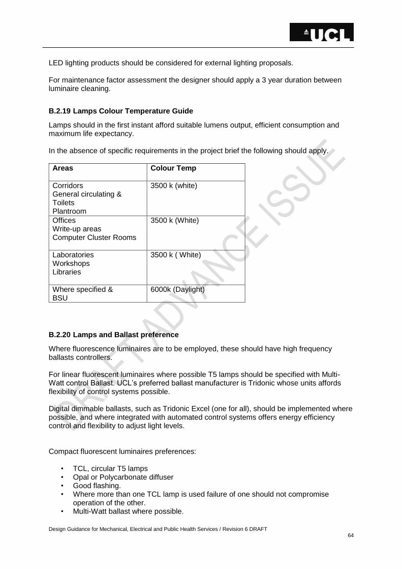
Design Guidance for Mechanical, Electrical and Public Health Services / Revision 6 DRAFT 64
LED lighting products should be considered for external lighting proposals. For maintenance factor assessment the designer should apply a 3 year duration between luminaire cleaning.
B.2.19 Lamps Colour Temperature Guide
Lamps should in the first instant afford suitable lumens output, efficient consumption and maximum life expectancy. In the absence of specific requirements in the project brief the following should apply.
Areas Colour Temp
Corridors General circulating & Toilets Plantroom
3500 k (white)
Offices Write-up areas Computer Cluster Rooms
3500 k (White)
Laboratories Workshops Libraries
3500 k ( White)
Where specified & BSU
6000k (Daylight)
B.2.20 Lamps and Ballast preference
Where fluorescence luminaires are to be employed, these should have high frequency ballasts controllers. For linear fluorescent luminaires where possible T5 lamps should be specified with Multi-Watt control Ballast. UCL’s preferred ballast manufacturer is Tridonic whose units affords flexibility of control systems possible. Digital dimmable ballasts, such as Tridonic Excel (one for all), should be implemented where possible, and where integrated with automated control systems offers energy efficiency control and flexibility to adjust light levels. Compact fluorescent luminaires preferences:
• TCL, circular T5 lamps • Opal or Polycarbonate diffuser • Good flashing. • Where more than one TCL lamp is used failure of one should not compromise
operation of the other. • Multi-Watt ballast where possible.
Design Guidance for Mechanical, Electrical and Public Health Services / Revision 6 DRAFT 65
• Low Voltage halogen spot lights should be avoided where possible due to their high maintenance.
LED luminaire light engine and control gear should be high output, high efficiency LED chipset optimised for the application and should include dimming options for DALI and DSI.
B.2.21 Lighting Control Systems
Control of lighting should enable user interface as well as provide energy conservation in relation to daylight contribution and occupancy. It is strongly recommended that design proposals for automated controls are approved by lighting controls specialist to ensure complete coverage and reliable operation. Control Systems should:
- Be operating on digital control protocols such as DSI or DALI - Incorporating bus cabling and driver devices, linking all lighting control devises. - Employs microwave sensors for more reliable detection where this is possible. - Implement Corridor linking and Daylight sensing. - Utilise digitally dimmable control gear in luminaires to regulate light output and
maximise energy efficiency. - Interface with AV systems.
User interface should be allowed, as wall mounted switches where possible compatible with the system and where necessary supplemented with hand held controllers. Final requirement should be agreed with the UCL EM&I Electrical engineer. Record information of the lighting control system should be included on drawings, and should consist of Addresses, Zonal information, device locations, cable routes and an indication of the control strategy. Digital DSI and DALI lighting protocols now provides a common platform for system to be developed around employing intelligent control ballasts with individual addressability and should be utilised where possible on designs. UCL standardises on distributed intelligence systems of the following manufacturers:
1) Ex-Or (Honeywell) Lighting Ltd - MLS system 2) Thorn Lighting – Sensa Link
B.2.22 Specialist Lighting
All lighting designs associated with the floodlighting of buildings, Theatre lighting of stage areas, and feature lighting of moving objects or water features should be referred to a lighting specialist with a proven track record. Photographic Darkrooms should be fitted with tungsten halogen or GLS lamp luminaires for general lighting to eliminate possible afterglow issues commonly associated with discharge lamps.
Design Guidance for Mechanical, Electrical and Public Health Services / Revision 6 DRAFT 66
B.2.23 Emergency Lighting
UCL’s buildings are served by emergency lighting in accordance with BS 5266 and BSEN 62034. UCL’s policy of emergency lighting design: UCL’s requirement is to have LED standalone addressable emergency lighting in lieu of central battery system. Any deviations to this being agreed with UCL EM&I and only considered where a separate system could adversely impact or not be practical solution. Non Illuminated exit signs should be provided as per the UCL Fire Safety Technical Guide, TN 020 Emergency Lighting – UCL General Design Guidance. Non-maintained surface / recessed (as appropriate) luminaires should be installed as standalone 3 hour duration units obtaining live feed from the local associated lighting circuit, Conversion / Combined emergency luminaires shall not be installed, except for the following exceptional conditions. In each one of these conditions, the designer must seek specific written approval from UCL E,M&I :
Areas with high ceilings and where wall mounted emergency lights would not meet the requirements.
High Profile aesthetically pleasing areas where a standalone emergency light would adversely compromise the effect of the space or not be a practical solution. (ie Listed buildings). In these instances, small recessed LED’s must have been considered and discounted prior to seeking approval for Converted / Combined Luminaires.
Where space restrictions dictates in listed buildings retaining a certain period feel.
Emergency units to be incorporated within luminaire or remote mounted only on luminaires that are mounted in accessible suspended ceilings.
LED emergency lighting must be installed as the UCL standard, however where LED lighting may not be suitable traditional light sources may be considered. For refurbishment projects the contractor/design team should carry out necessary survey to establish the existing interface and testing facility and protect the integrity of existing loops. Wherever possible, as alternatives to the normal fluorescent units providing the required lighting levels are achieved. UCL would however, still require LED solutions to be compatible with the testing system being employed throughout the building. B.2.24 Emergency Lighting Testing Systems
Testing systems should be in accordance with BS 5266. Addressable testing system should be as a UCL approved system installed fully to the manufacturer’s recommendation and in accordance with UCL’s policy: Manual test key switch system (preferably ganged with the local light switch control or located at the distribution board positions), should be provided where an automated addressable testing system neither exists nor is proposed as part of the project specific brief.
Design Guidance for Mechanical, Electrical and Public Health Services / Revision 6 DRAFT 67
Emergency Lighting Addressable System Addressable emergency lighting testing systems has been installed in a number of buildings and the policy is to extend the coverage where possible. Where systems currently do not exist the Electrical Team Leader (ETL) should determine the requirement for the project. Where a system exists the designer should allow for their adaptation for the new proposals, and should liaise with the system manufacturer to develop the design and work elements. For existing buildings where no system currently exists, UCL’s preferred manufacture is Zumtobel On-Lite system. Currently the Addressable lighting system implemented at UCL are supplied by: Advanced Electronics Ltd. Morley House West Chirton North Shields Tyne & Wear NE29 7TY Tel : 0191 257 6361 Fax: 0191 257 6373 Zumtobel On-Lite product (formally Thorn Explorer Vision) Zumtobel Lighting ltd Silver Screens, Elstree Way Borehamwood Herts WD6 1FE Tel: 020 8732 9800 Fax: 020 8732 9801 In all cases where works are carried out on the system, commissioning back to head end PC on the main site is required, with handover constituting:
• A fault free 3 hour duration test on system (and printout where necessary). • CD or USB with set-up and back-up files of the system as commissioned. • Commissioning Certificates and Random Check list. • Record information should include drawings with addresses, device numbers, and or
group numbers; indication of routes of communication cabling plus other associated equipment.
The employment of either of these systems should be based on the guidance of UCL’s Engineers with only one of these systems being installed within any given building. The designer must liaise with the EM&I team for final confirmation on system to be installed on each project.

Design Guidance for Mechanical, Electrical and Public Health Services / Revision 6 DRAFT 68
The designer should also allow for the installation of data socket adjacent to the control panel of these systems and advise the PM or ETL of the port numbers to enable UCL to arrange configuration of the IT network, for secure communication to the remote PC.
B.2.25 Fire Alarms and Detection System
Designs to comply with:
• BS 5839, • CIBSE TM16, • CIBSE Fire Engineering Guide E, • UCL’s Fire Technical Guides (from Fire Safety Advice website or Fire Officer), • UCL insurance requirements, • BS 6266 Code of protection for electronic equipment installations • BS 7273-1 Extinguishing systems • UCL Fire notes/Guidance: http:www.ucl.ac.uk/estate/maintenance/documents.
UCL’s policy is generally to protect Life (Category group L). However not all systems will fit neatly into the different recommended categories for an entire building and as such for higher risk rooms and property protection must be assessed and allowed for as necessary. Implement property protection policy where stipulated or where value of equipment within area or associated with facility is £500,000 or more. The specification should cover:
• Type and location of detectors, sounders, control panels, keypads and power supplies.
• Cable type and method of installation. • Alarm signalling. • Communications / reporting function. • Connection of ancillary services. • Smoke extract systems. • Fireman’s switches. • Warning and evacuation signs • Other Ancillary services connections • Override switch on fire alarm panel to isolate plant, gas valves, fire dangers etc.
during testing. • Facilities for Equality Act alerting and evacuation.
Loop and sounder circuits should be sized to ensure fault free operation so that protective devices are not blown or tripped during Fire Alarm activation. All systems should be zoned, including on Addressable systems, and cable routes indicated. In the event that the design proposal constitutes a deviation from British Standards recommendations this should be agreed with UCL’s Fire/Safety Officer and all relevant interested parties, ensuring this is fully documented on commissioning certificate. UCL’s policy employs Apollo protocol devices and open protocol panels in accordance with UCL’s Fire Safety Technical Notes.
Design Guidance for Mechanical, Electrical and Public Health Services / Revision 6 DRAFT 69
Preferential panel manufacturer Morley IAS, Advanced. Fire Alarms Ancillary Systems Allowance should be made for the integration of the following other services to the fire alarms system:
• Equality Act systems (such as Disabled pager panel) • Sprinkler systems • Door closers / door hold–open devices. • Fire fighting services • Passenger Lifts and Mechanical control panels. • Security systems.
Note: The interfacing of the above systems should not compromise the reliability and functionality of the Fire Alarms and detection system. All designs should be approved by UCL’s Fire/Safety Officer. A Specialist contractor should provide the fire alarm design certificate (BS 5839 part 1 2002 + A2 2008 G1) For refurbishment projects the contractor/design team should carry out necessary survey/decommission within the construction areas of the building and protect the integrity of existing system. For Data centre/comms room and other high risk areas should be provided with suitable fire suppression systems. UCL has a 24 hour 365 days of the year Communication centre which monitors all alarm signals. The designer should liaise with the Comms Room manager with regards to requirements for linking the system to this monitoring station. Cabling should be specified as enhanced type cables. Where cables are clipped to the ceiling, metal type cable clips should be utilised at every 45mm centres.
B.2.26 Disable Alarms & Services
In meeting the Equality Act requirements the following should be considered during design and allowed for where feasible:
• Electrical supplies to disabled lifting systems. • Increase illumination levels in circulating areas • Mounting heights of accessories in accordance with Equality Act legislation. • Access facilities including allowing for door hold open devices where necessary. • Egress facilities via evacuation lift for persons with mobility problems. • Services for Refuge Areas • Induction loops for general circulating areas and office. • Disabled pager alarms system integrated to BS 7807. • Flashing xenon light on alarm circuit of fire alarms. • Disable call systems in toilets and other areas as necessary. • Panic alarms • Induction loops of sound field systems for Lecture Theatres and Seminar rooms.

Design Guidance for Mechanical, Electrical and Public Health Services / Revision 6 DRAFT 70
B.2.27 Induction Loops
Audio Frequency Induction Loop Systems (AFILS) should be designed and installed to conform to BS 7594 BS 6083 IEC 118 Part 4. A conformance certificate should be issued on completion, clearly stating the dB level of the AFILS and any adverse characteristics of the installed system. Where Disable pager panel is to be installed on a Fire Alarm System both the power supply and signal link must be monitored. For systems that require linking back to the Comms Room monitoring station a normally closed volt free pair relay should be allowed on the control panel. Liaise with the UCL EM&I team for wiring and point of interfacing information.
B.2.28 Ancillary Alarms
Other alarms systems can generally constitute Safety monitoring systems where hazards exits. Systems proposed are to be approved by the UCL EM&I team. Communication link back to comms room requires NC volt free relay.
B.2.29 Intruder & Panic Alarms
System design to conform to all latest relevant standards. Installing companies should be NSI or SSAIB approved. Liaise with the UCL EM&I team on proposed designs and interfacing system with Comms Room respectively.
B.2.30 Access & CCTV Security Systems
System design to conform to all latest relevant standards and UCL’s “Electronic Access Control Turnstile Integration Specification Guidance”. Liaise with the UCL Security team for information on system design and interfacing system with Central Security Comms Room.
B.2.31 Communication Systems
In accordance with all relevant Standards as outline in UCL’s Standard Specifications for IT Voice and Data networks Installations from Nigel Hayward.

Design Guidance for Mechanical, Electrical and Public Health Services / Revision 6 DRAFT 71
B.2.32 Media Systems
This generally relates to Audio Visual systems design brief for which should be obtained from UCL’s Information Systems Division through the Project Manager. All design proposals should be submitted back to the said department for final approval.
B.2.33 Labelling of Services
The labelling for distribution systems should be carried out with engraved traffolite Black on White, fixed with plastic rivets of nylon screws.
MAIN SWITCHPANEL: (5mm lettering)
Fields Details Explanation
Ref:
UCL PANEL A
This should be the main switchpanel ref.
Fed from: Somewhere Switchroom “MP2-7”
Details of where the supply emanates from (item in quotation is the cubicle ref if applicable)
Service Rating:
400A Maximum current rating of the supply.
Protection Type: MCCB
Up-stream protection device
Incoming Cable:
240mm/XLPE/SWA/LSF + CPC
Self explanatory (should include size of CPC)
OUT GOING DEVICES CUBICLES: (5mm lettering)
Fields Details Explanation
Ref:
Panel A/4 This should be the particular switch cubicle reference (example adjacent Panel A/4 representing Panel A cubicle # 4)
Serving
Reference and or description of equip / DB being served.
Location Location of equipment or distribution board being served.
Max Device Rating:
Self explanatory
Device Setting
Applies to MCCB devices that allows for adjustment of “In” protection level
Cable Size / Type:
Self explanatory (always indicated cpc where installed)
Device Type:
Manufacturer and order Ref:
Note: spare cubicles to be labelled with Ref and other fields blank.

Design Guidance for Mechanical, Electrical and Public Health Services / Revision 6 DRAFT 72
For field sub-mains and final distribution boards. (5mm lettering)
Fields Details explanation
Ref:
Gnd/DB1 Identity of distribution board (either obtained from Estates or as per design drawings)
Serving
Ground floor lighting and power.
Reference and or description of equip / DB or services being supplied.
Fed From Tap off on Rising busbar. Equipment / system serving this unit.
Cable Size / Type: Self explanatory
For field Switch/fuse, Fuse/switch and Isolators. (3mm lettering)
Fields Details explanation
Ref:
DB1/ Cir4 Identity of circuit (taken from upstream DB circuit way)
Serving
Any Equipment. Reference and or description of equip or services being supplied.
Fed From Some DB Equipment / system serving this unit.
Tap-off boxes to have ref. identification only.
Cables should be labelled with the following information (3mm lettering)
Fields Details explanation
Serving
Reference and or description of equip / DB being served.
Location Location of equipment or distribution board being fed.
Cable Size / Type:
Self-explanatory
Other systems to be labelled:
• All socket outlets and power disconnectors – labelled with circuit ref. • All conductors in distribution boards, MCC etc. to be labelled with termination ref. • All fire alarms equipment with necessary addresses and zones. • All emergency lighting addressable luminaires with addresses etc. • All emergency luminaires identifying them as emergency lights. • Any other control / monitoring system that required peripheral connections to be
identified.

Design Guidance for Mechanical, Electrical and Public Health Services / Revision 6 DRAFT 73
These labels can be of a stick on type to be approved by UCL.
Design Guidance for Mechanical, Electrical and Public Health Services / Revision 6 DRAFT 74
MECHANICAL SERVICES
C.1 MECHANICAL DESIGN CRITERIA
The following criteria has been provided for guidance only. The Building Services Consultant should insure that all design criteria are compliant with all current mandatory standards and are in line with the recommendations of CIBSE Guide A, BSRIA or other such recognised industry bodies. Any deviation from these standards and guidelines should be identified and agreed with the UCL EM&I team prior to commencing the design.
C.1.1 Environmental criteria, External Conditions
Summer (General) 30°C dry bulb 20.5°C wet bulb Summer (BSU areas) 32°C dry bulb 22.5°C wet bulb Winter (General) -3°C dry bulb saturated Winter (BSU areas) -5°C dry bulb saturated Frost coils on air handling plant, when units are off should be sized to provide frost protection and meet design with ambient external temp of –5°C; and protect plant from freezing down to –8°C. Heat rejection plant to be selected to achieve design at 32°C dry bulb temperature but should continue to operate satisfactorily with an ambient dry bulb temperature of 38°C.
C.1.2 Environmental Criteria, Internal Conditions
Teaching and Research Laboratories, Support Areas, offices etc. Winter 20°C dry bulb min RH uncontrolled. Summer (when cooling is specified) 26°C dry bulb max RH uncontrolled (unless demanded by a process) BSU Areas 55% RH ± 10% Each holding room should be capable of being held at any set point between 19-23°C ± 2°C unless directed otherwise by the User Department on room data sheets, to be considered on a project by project basis along with upgraded self-contained units. Lecture Theatres Winter 21°C dry bulb ± 2°C within occupied zone RH 30% minimum
Summer 24ºC dry bulb ± 2°C within occupied zone. Seminar & Tutorial Rooms Winter 20°C dry bulb minimum Summer 24°C dry bulb max (where cooling is specified) RH uncontrolled. Stairs & other circulation Winter 18°C dry bulb minimum spaces on refurbished buildings. New buildings may not require heating to these areas.
Design Guidance for Mechanical, Electrical and Public Health Services / Revision 6 DRAFT 75
C.1.3 Ventilation Requirements
Rates not to be higher
Teaching & Research Labs Rate to be determined by assessment of required dilution or containment with increased levels of ventilation where dictated by high density of fume cupboards or special extracts. Rate should be the lowest to meet these requirements. BSU Areas 20 air changes per hour min with increased rates to suit heat gain if necessary. Lecture Theatres 10 l/s per person Seminar/Tutorial Rooms 10 l/s per person where cooling is
provided with increased rates as appropriate where not cooled.
Toilets 10 air changes per hour extract, 8 air changes per hour make up (where appropriate to provide make-up air). Shower rooms 15 air changes per hour or an extract rate of 30 l/s per shower whichever is the greater. Offices 10 l/s per person where cooling is provided (subject to a minimum 3 air changes per hour or 24 l/s per office) with increased rates as appropriate where not cooled.
C.1.4 Filtration Standards
Teaching and Research Laboratory EU3 pre-filters with EU8 bag filter with increased levels where dictated by special facilities. All other areas EU3 pre-filters with EU6 bag filters.
C.1.5 Internal Heat Loads
In addition to the solar, lighting, and heat loads from occupants, the air conditioning/cooling systems should be designed to offset the loads from equipment and computers, derived from room data sheets. Should the stated equipment gains result in an exceptionally high load expressed in terms of watts per metre squared then this should be discussed with the UCL EM&I team to decide if a diversity or similar reducing assessment is appropriate.
Design Guidance for Mechanical, Electrical and Public Health Services / Revision 6 DRAFT 76
C.1.6 Water Services
i) Cold Water Storage Laboratories (category 5 water) To be assessed from room data sheets and discussions with users. Domestic (category 1 water) 45 l/person Lab staff 20 l/person Student ii) Hot water Storage Domestic (category 2 water) 4.5 1/person (to be considered on a project by project basis) Laboratories (category 5 water) To be assessed from room data sheets and discussions with users. C.1.7 Noise criteria
Internal noise levels Type of Accommodation Sound Level Range (NR) Lecture Theatres 20-25 Seminar Rooms 25-35 Laboratory (Without fume cupboards) 30-40 Laboratory (With fume cupboards) 40-50 Toilets 35-45 Showers 35-45 Print Room 35-45 Research Write-Up 30-35 Tissue Culture 35-45 (to be confirmed on a project by project basis) BSU To comply with Home Office Code of Practice.

Design Guidance for Mechanical, Electrical and Public Health Services / Revision 6 DRAFT 77
C.1.8 External noisearising from installed plant and equipment
Noise arising from installed plant and equipment is becoming increasingly important. Failure to comply with the noise criteria and requirements set out in planning consents can lead to enforcement action being taken by the Local Authority for breach of statutory nuisance. Even if statutory nuisance is not demonstrated, noise complaints are time-consuming and expensive to investigate. The noise levels acceptable for planning are generally be determined by Local Authority requirements. The requirements of LB Camden are typically expressed as: “Noise levels at a point 1 metre external to sensitive facades shall be at least 5dB(A) less than the existing background measurement (LA90), expressed in dB(A) when all plant/equipment (or any part of it) is in operation unless the plant/equipment hereby permitted will have a noise that has a distinguishable, discrete continuous note (whine, hiss, screech, hum) and/or if there are distinct impulses (bangs, clicks, clatters, thumps), then the noise levels from that piece of plant/equipment at any sensitive façade shall be at least 10dB(A) below the LA90, expressed in dB(A).” In general there are three user requirements which need to be carefully managed in order to comply with planning criteria
The expansion of working hours and move to 24/7 operation means that more equipment will be required to run out of hours or over night
The requirement to operate more temperature-sensitive equipment and processes leading to a consequent requirement for additional process cooing
User expectation to work in a temperature-regulated environment leading to a requirement for increased comfort cooling
At design stage 1 number of factors need to be considered if an installation which meets user requirements is also to meet planning requirements: Who will be affected by the noise? Consideration needs to be given to those who might be affected and when they might be most sensitive to noise. For residential premises this might neighbouring residences at night time, for a place or religious worship this might be during the day time on weekends. What existing plant is already in operation? Any new plant will add to the noise from existing plant. It is important that combined noised from both new and existing plant meet the noise requirements for planning criteria. Where the existing plant installation is extensive and/or complex then the noise modelling must be sufficiently robust to clearly demonstrate that the planning criteria will be met at all times. Selection of quiet equipment Consideration should be given to the selection of equipment which comfortably operate within the acoustic constraints as set out in the planning requirements. Reliance cannot be placed on the installation of acoustic shielding to mitigate the effects of noisy plant and equipment as planning permission may not be given for the shielding. Location to avoid noise reflection and acoustic resonance Consideration should be given to the location of newly installed equipment to minimise noise reflection and/or amplification through acoustic resonance. Here again acoustic modelling can be employed to predict the operational noise levels from a particular installation. Placement to allow changing of filters and maintenance of moving parts

Design Guidance for Mechanical, Electrical and Public Health Services / Revision 6 DRAFT 78
It is important that plant are installed to allow easy access for maintenance operations, including
Replacement of filters
Tensioning of drive belts
Lubrication and servicing of motors Operational hours Plant and equipment should be configured not to operate outside of the agreed operating hours. Where a building has 24/7access but the plant is permitted to operative only during restricted hours neither user controls not automatic presence/absence detection should be configured so as to cause the equipment to operate outside these hours. Where night time operation is required the equipment should be configured, where possible, to operate in quiet or night time mode if this is provided. Sequential start-up Where services are provided by more than one item of plant or equipment, they should be configured so as to start up sequentially, so as to allow each item to adjust to its running load before the next item is started. The same applies to shut down. These actions allow for a gradual, rather than sudden, transition in noise level. Acoustic shielding Acoustic shielding should be employed only once all other options have been exhausted.
The visual massing associated with shielding may not secure planning consent
The shielding applies a fixed attenuation value which may not be sufficient if/when the plant/equipment are modified or adapted in the future

Design Guidance for Mechanical, Electrical and Public Health Services / Revision 6 DRAFT 79
C2 GENERAL REQUIREMENTS
ZONING
NEED TO HAVE APPROPRIATE ZONING – TAKING INTO CONSIDERATION DIFFERENT USES OF THE BUILDING
C.2.1 Utilities and Infrastructure
No utility supply contracts may be entered into by contractors in UCL’s name. Where new supplies or changes to existing supplies are required these must be discussed and agreed with UCL’s Energy Manager – who will arrange any new contracts to be drawn up. Gas
Where gas is required, buildings should be provided with a main incoming gas meter and governor in a ventilated room including high and low level ventilation in accordance with IGE and Gas Safe Regulations. New meters should be supplied by the Statutory Authority in a position agreed with them and UCL’s Energy Manager. The meter and shutoff valve should be fully accessible from the front. The meter should have an integrated Automatic Meter Reading device (with a 30 minute read schedule). The gas meter should be capable of accepting up to 120% of the design load. All meters should be ‘low pressure drop’ type, pulsed, and connected to the BMS for monitoring of consumption (in 30 min intervals). All gas solenoid valves should be selected with a ‘low pressure drop’ in order to comply with the Gas Installation Regulations. Use of boosters should be avoided where possible. All gas running within buildings should be ventilated either via suitable high and low level grilles in risers which link to an external space or where this is impractical, via pipe in pipe installation. Water
Buildings should be provided with a metered incoming water supply from the Statutory Authority’s network. New meters should be supplied by the Statutory Authority in a position agreed with them and UCL’s Energy Manager. The Authority meter should be pulsed to allow for BEMS monitoring of consumption. Where the statutory meter is located remote from the building boundary, a second client check meter with BEMS connected pulsed output should be provided and the flows compared to act as leak detection. The BEMS should also use intelligence to determine demand patterns over time and identify out of range use. Commissioning must ensure that the connection of the meters to the BMS system has been achieved. Steam The existing steam district heating system is being phased out. This means that no new connections should be made to this system. This includes proposed works where it is

Design Guidance for Mechanical, Electrical and Public Health Services / Revision 6 DRAFT 80
proposed to reuse existing connections. Any buildings which may be effected by this should be discussed with the UCL EM&I team at the earliest stage in order to agree a suitable alternative strategy. All new or replacement interfaces should take precedence from the CHP District Hearting Network wherever feasible. District heating –move some things there. Approvals process No tampering primary side C.2.2 Pipework Systems
No plastic pipework systems to be specified for any heating, cooling or domestic hot and cold water systems, except in specific laboratory applications. Alternative materials or systems such as thin wall stainless steel may be considered through prior agreement with the UCL EM&I team. All pipework insulation should be installed by the pipework installation subcontractor and not the lagging subcontractor complete with clear external identification, to include:
• Service identification • Direction of flow • Un insulated pipework dimension
All flanges and valves should be insulated alongside the pipework.with Velcro covers. Where pipework is being installed on an existing system, any missing insulation within the system should be re-instated as part of the works. i Prior to the start of a project the Building Services Consultant should obtain a Legionella risk assessment for all existing systems from the UCL EM&I / maintenance team. A water hygiene review should be carried out at Stage D with a detailed review and verification of the Consultants design by a UCL approved specialist and the system treatment and maintenance regimes presented to the UCL EM&I team for comment and approval prior to proceeding to detailed design. The dosing of systems with chemicals should be avoided wherever possible with specific attention being given to the overall system filtration / strainer requirements. Consideration should be given to equipment warranties. Where buildings or areas are being refurbished all redundant pipework shall be removed back to the tee on the live pipework and capped off. Transducers should be specified on all secondary circulation pumps and other main plant items to monitor water flows through BMS alarms in order to assist with proactive maintenance regimes. Binder test points should be provided on all systems for testing, sampling and commissioning purposes, specifically the monitoring of calorifers / storage vessels water temperatures for system analysis. Dead legs should be avoided on all pipework systems.

Design Guidance for Mechanical, Electrical and Public Health Services / Revision 6 DRAFT 81
Refer to the preferred manufacturers schedule for recommended all pump and pressure set suppliers. Where practicable toilet facilities, cleaners cupboards and catering areas should be provided with automatic motorised shut off valves on the cold water supplies linked to presence detection. This function should incorporate the full requirements / specification identified under BREEAM. All heating and chilled water systems should provide accessible shut off facilities to all floors or appropriate zones for system maintenance, leak isolation or future fit-out activities. These valves should be motorised with BMS monitoring and control facility. C.2.3 Heating, Boilers & Humidification
Buildings on the Central Campus
• Do not use 3-port diverting valves which would divert water at flow temperature back to the return in low load conditions. Utilise 2 port control valves and variable volume pumps taking due regard of minimum flow requirements of the pumps.
UCL has a district heating system serving the majority of buildings on the central campus. New buildings or refurbishment projects on this campus should be connected to this heat source unless this has been agreed with the Energy Manager. Projects outside the main campus should be provided with heating appropriate to the scheme.
1. District heating for all main campus and IoE sites. 2. Off campus – Condensing boilers 3. Ground/water source heat pump for major refurbishment 4. 5. District heating
Systems must be designed to keep the secondary return temperature to the PHE below 70C to ensure maximum efficiency of heat recovery from, and cooling of, the CHP engines and to avoid the need for waste heat rejection. The primary district heating is designed to maintain 80C on the secondary flow when heating is required. This results in the following design criteria being generally adopted: Tables around operating temperatures for VT and CT
• LPHW to be designed for 80C flow and 65C return. • PHE designed to operate at 82C maximum flow • Maintain a minimum flow through the PHE so that the immersion sensor in the
secondary flow will record a true temperature (if designing a total variable temperature system then this should include a constant volume loop with mixing valve set to control on the return temperature to the PHE. Details to be discussed with Estates engineers).
• Provide a volt free signal pair to the primary control panel to indicate that heating is or is no longer required (e.g. to coincide with optimum on/off)
Buildings outside of the Central Campus or IOE - boilers Buildings outside the reach of the district heating network should be provided with high-efficiency condensing gas boilers which are fully automatic in operation. Energy efficiency and lifecycle costs should be the guiding principles in the selection of system type and equipment selection. Systems should be designed with adequate provision to maintain suitable heat output in the event of a failure of a single item of heating output. This will

Design Guidance for Mechanical, Electrical and Public Health Services / Revision 6 DRAFT 82
generally require a minimum of two boilers rated at 66% of design load or three boilers at 40%. Considering improvements to the building. The preferred system will utilise direct boiler flow temperature modulation and maximum use of condensing modes particularly within new build projects. Return temperatures of 30°C-40°C are preferable but must be considered in relation to the size and cost of heat emitters. Consideration should be given to separate gas fired water heaters. Boiler selection should seek to achieve class leading reduction in emissions (NOx <40mg/kWh) and high overall efficiencies. All plant and equipment should be selected to operate within acceptable noise levels. Each gas fired boiler should be able to modulate and turn down to a minimum of 20% of the maximum output and accept a variable volume flow. The gas fired boilers should have stainless steel heat exchangers, a large internal water capacity and should be capable of operating with a variable flow volume. Ventilation to boiler plant rooms should be provided at high and low level in accordance with BS 5440 or BS 6644 where applicable. Boiler flues should be stainless steel, twin walled and insulated and should be fire rated for 2 hours at 300°C for the entire length. Flues should be provided with trapped drain for rain water and condensate, which should be taken back to the nearest gully in the plant room and safely discharged. Ventilation linked to operation of the plant. Heat pumps In some instances, the use of heat pumps may be an appropriate source for heating and/or cooling. Either air-source or ground-source heat pumps may be considered, however close attention must be paid to the COP and SEER of the unit by selecting appropriate operating temperatures. Ground source heat pumps should have a minimum COP of 3.5 in heating mode. Specialist advice. Typically heating should be no greater than 40-45°C flow and cooling should be no less than 12-15°C flow, although there may be exceptions to this. Where ground source heat pumps are used, it is important to ensure that there is either a balanced heating or cooling load or that the ground is suitably recharged over the year (for example by using solar collectors to deposit heat into the ground in summer for predominantly heating systems, or by using dry coolers to reject heat in winter during predominantly cooling systems). Plate heat exchangers may be required to separate external glycol circuits from systems within the building. All glycol systems should contain food-grade glycol. Space heating should generally be by radiators with TRVs on a variable temperature (VT) circuit. VT circuits should be provided with independent run and standby pumps complete with variable speed drives – control of pumps should be pressure led (i.e. taking into account TRV use). Systems should be split into primary and secondary systems where local plant incorporating multiple boilers is used. Radiator valves should be lockable, and tamper/vandal proof. The Thermostatic Radiator Valves (TRVs) should be to BSEN215-1 and BS7556. Heat emitters within disabled toilets or similar areas should be of the low surface temperature type with a maximum surface temperature of 43°C. Where fan coils or fan convectors are proposed, fans and motors should be mounted on a chassis independent of the convector casings. The motor should be positioned prior to the convector element to eliminate damage by excessive air temperatures. Fan convectors should be served by constant temperature circuits only.
Design Guidance for Mechanical, Electrical and Public Health Services / Revision 6 DRAFT 83
Valved flushing loops should be fitted at all fan convectors and fan coil units. Fan coil units should be complete with internally fitted thermostats and low temperature cut-out switches. In-line strainers should be fitted before all control valves on fan coil units. Access panels should be provided to facilitate easy maintenance of filters, motors, control valves etc. Internal filters should be fitted and have an atmospheric dust spot efficiency of at least 55% when tested in accordance with BS 6540. Control should be by interface units to the BEMS system. Use of humidifiers should be avoided where possible, however where the internal environmental conditions required necessitate the use of humidity control, the preference is to use resistive steam type as opposed to electrode boiler due to the reduced maintenance and spares costs. It may be necessary to provide Reverse Osmosis (RO) water to the humidifiers. Where in-duct humidifiers are installed, ensure the downstream absorbption distance is sufficient; typically 1.5m. On larger installations, consider the use of gas-fired humidifiers rather than electric in order to minimise the electrical load. Ultrasonic Gas Electric as a last resort Minimum amount of humidity required. Heat station (primary to secondary) As detailed in the Heat Network (Metering and Billing) Regulations 2014, heat meters must be fitted to meter any connection from the district heating system to a building. Where new boilers are installed, there should be a heat meter to monitor heat output from the boiler. All heat meters installed must be connected to the BMS system (KW and kWh). Heat meters should be Kamstrup x x. Rob Durno to comment C.2.4 Cold Water Services
Systems should be designed in accordance with the Water Regulations 1999 and CIBSE TM13 and HSG guidance L8. Thames Water have instigated a programme to reduce the pressure in their mains to reduce leakage rates. They are only bound to provide 1 bar gauge pressure at the main and may progressively reduce to this minimum. Projects involving provision of new storage systems and substantial mains water distribution should therefore be designed with booster sets. Consideration should be given to building height when determining whether booster sets are necessary. Booster sets should include duty/standby pumps as a minimum with IE2 or IE3 motors and auto-changeover. Booster sets should be provided with a control panel. Water consumption can be less than that indicated by design guides and interpretation of occupancy levels from room data sheets, leading to hygiene risks due to low turnover of stored water. Water cisterns should be sized in the normal way but fitted with Aylesbury “KB” type delayed action float valves with adjustable water and differential levels. The levels should initially be set at lower than the listed actual capacity of the cisterns and should be adjusted to suit actual turnover under “in-use” conditions. Tanks should consist of pre-insulated sectional GRP panels. All tanks should have a minimum of 900mm clear above for access and should be installed on plinths a minimum of

Design Guidance for Mechanical, Electrical and Public Health Services / Revision 6 DRAFT 84
500mm high. Access should be via external galvanized steel ladders and internal stainless steel ladders. Screened vents should be minimum 100mm diameter. In new buildings the cold water storage for laboratory and for domestic use should be totally segregated in accordance with the water categories. In existing buildings the extent of the segregation should be discussed with the UCL EM&I Team to agree what can be reasonably achieved within the cost restraints of the project. The minimum requirement should be to segregate the water services in the new project area even though these might be connected to a common point outside the project area. This will provide a ready point of connection when services to the remainder of the building are brought into line with the regulations. Although the risk assessments for a particular project may identify laboratory use water as category 4, all laboratory use water (except wash basins in laboratories) should be designed as category 5. The reasons for this are:
• RPZ valves are not generally acceptable due to the costs to maintain these on a register and the ongoing maintenance liability.
• Laboratory use can change within a short time and flexibility of use is required. The wash basin provided in a laboratory for use at point of exit should be served with category 1 domestic water. If eye-wash points are specified then these should also be served with category 1 domestic water. Category 5 water supplies should generally be boosted. Water purifiers should be served by category 5 water. Where extending from existing CWS circulation pipework, the new pipework should be of the same material as existing to avoid dezincification. However, galvanised steel pipework should not be installed in UCL buildings and all existing removed wherever practicable and or economical. Plastics pipework systems will not be considered unless by approval of the UCL EM&I team or for specialist requirements with labs etc. All other pipework systems should be either copper or steel. Stainless steel braided EDPD (or similar) flexible hoses should not be used for final connections to outlets. Corrugated copper flexible connectors are an acceptable alternative, A suitable water treatment system should be specified in agreement with the UCL EM&I team where required. Services should be labelled “cat 1 water” or “cat 5 water” Provide combined constant flow regulators/ isolation valves on all final connections to all appliances to provide system flow balancing. Back flow prevention should be provided as necessary. Where water pipework runs externally, it should be trace heated. Provide 240 volt solenoid valves on the CWS to all toilet areas, in order to isolate the water supplies when the toilet areas are not occupied (this should be achieved by connection to the local PIR within the toilets via a relay where two WCs are connected to a single solenoid valve).

Design Guidance for Mechanical, Electrical and Public Health Services / Revision 6 DRAFT 85
C.2.5 Hot Water Services
Hierachy
1. If on network connection to PHE
2. Direct fired gas fired water heaters (where alongside condensing boiler) or from existing non-condensing boiler plant
3. Instantaneous water heater
4. Electric point of use
Systems should be designed in accordance with the Water Regulations 1999 and CIBSE TM13 and HSC guidance L8. On the main campus primary hot water for category 2 domestic use should generally be provided by a new PHE, connected to the CHP district heating system or connection to the secondary side of an existing PHE, as described for the heating. Projects outside the main campus should be provided with HWS appropriate to the scheme. If considering utilising the secondary LPHW from a PHE as primaries to HWS cylinders then 2 port control of the primary HWS should be employed. However, consideration should be given to the fact that in summer conditions the very low primary flow to maintain HWS temperatures through a large combined PHE may result in the primary heat meter being unacceptably inaccurate dependant on the turn-down ratio. Further, if the requirement to keep the return temperature to the PHE below 70°C is designed to be achieved by an injection system then this could result in the heating flow temperature being below that required for pasteurisation in low heating load conditions. Consideration should be given to the use of a dual PHE configuration with 1 unit serving the heating and 1 unit serving the DHWS. Where gas-fired hot water plant is selected for off-campus sites, this should be high efficiency with flue considerations as per that for boiler plant. User Departments should be consulted to establish the minimum number of hot water outlets required in a laboratory, as a hot supply is not always required to a laboratory sink. The laboratory hot water for small projects can be served by local electric water heaters connected to the category 5 boosted cold water, unless there is an existing category 5 HWS system available for connection. Where a larger number of laboratory outlets justifies the requirement for central category 5 HWS plant, then this should be totally segregated from the category 2 supplies with separate secondary cold feeds and circulation pipework. The wash basin provided in a laboratory for use at point of exit should be served with category 2 domestic water. Where either PHE or centralised hot water generators are used, the system should be designed flow and return. Where the domestic hot water system converts to flow only, electrical heat maintenance tape should be installed within 500mm of the outlet to ensure the water does not drop below the required temperature. The maximum temperature of this tape should be limited to avoid excess pressure build up due to expansion. Electric point of use water heaters should be on a time clock. Where local hot water heaters are used, any hot water pipe run supplying an outlet further than 3m from the water heater should also be fitted with heat maintenance tape to maintain the required water temperature.
Design Guidance for Mechanical, Electrical and Public Health Services / Revision 6 DRAFT 86
Hot water to washbasins in disabled toilets or general public/student use areas should be provided with point of use blending valves limiting the temperature to 43°C at the outlet. Hot water supplies to laboratories and staff accommodation are not considered “public” areas and do not require this control. Such sinks should be clearly labelled “Caution – very hot water”. Consideration should be given to the specification and use of Thermo taps wherever possible in lieu of blending values in order to avoid unnecessary dead legs. All water services branches should be provided with pressure regulation to limit pressure and control fluctuations where the static system pressure exceeds 2.0 bar. Where extending from existing HWS circulation pipework, the new pipework should be of the same material as existing to avoid dezincification. However, galvanised steel pipework should not be installed in UCL buildings and all existing removed wherever practicable and or economical. Plastics pipework systems will not be considered unless by approval of the UCL EM&I team or for specialist requirements with labs etc. All other pipework systems should be either copper or steel. Stainless steel braided EDPD (or similar) flexible hoses should not be used for final connections to outlets. Corrugated copper flexible connectors are an acceptable alternative, Deadlegs should be avoided where control sensors or thermometers etc are installed. Transducers should be provided on the delivery side of the pump to monitor operation via the BMS. Services should be labelled “cat 2 water” or “cat 5 water” C.2.6 Above Ground Drainage
It is recommended that an intrusive CCTV survey is undertaken on any existing building and associated drainage system including utility sewer connection outlets in order to define a full scope of works and risk assessment. Any remedial works to existing systems should be agreed with the UCL EM&I team. The above ground foul drainage systems should be installed to discharge all waste and effluent via gravity from all sinks, FF&E, sanitary fittings, kitchen appliances and any mechanical plant/equipment etc. Pipe work should be routed down through the building to ground level to connect to the below ground drainage system. The system should be a modified one pipe partially ventilated system. All internal vertical soil / waste vent pipes and foul water drainage pipes passing through occupied areas outside the main service risers should be insulated acoustically. Access should be provided on all vertical foul drainage stacks at 1200mm above each finished floor level, to the centreline of the access door and on horizontal pipe work in accordance with the requirements of the Building Regulations and BS EN 12056-2. All DX Units, fan coil unit and air handling units should be provided with condensate drainage, with the required air break detail. Where laboratory drainage is provided, this should carry chemical laden waste water including fume cupboards, laboratory benches, equipment, floor drains, etc. for final discharge into the below ground drainage system. The designer should check with the relevant department for information on the substances to be used with the drainage to ensure correct material selection. Typically, Vulcathene or similar drainage will be

Design Guidance for Mechanical, Electrical and Public Health Services / Revision 6 DRAFT 87
appropriate. The main ventilating pipe work should be installed to suit the design of both the above ground laboratory drainage system and the below ground drainage systems as necessary and should terminate to atmosphere. Rainwater systems should typically comprise gravity systems and these should be generally be collected from roof areas by a combination of rainwater outlets and gutters with downpipes. Pipework should be routed to discharge flows via gravity, vertically down through the building. All services passing through building fabric should be sleeved and insulated, and should be continued through the building fabric. All pipe work and equipment must be earth bonded. Access should be provided on all vertical internal rainwater pipes at 1200mm above each finished floor level, to the centreline of the access door and on horizontal pipe work in accordance with the requirements of the Building Regulations and BS EN 12056-3. Gradients of all rainwater pipes should be a minimum of 12mm/m, but should be to suit the individual flow characteristics of each rainwater pipe, to achieve a minimum self-cleansing velocity. Consideration may be given to the use of a syphonic rainwater system in conjunction with the Architect and input from a specialist system supplier. Suitable access provision should be allowed for throughout the building and the system to allow for adequate maintenance which should include for consultation with the UCL Facilities Department to determine any specialist traps and grease removal management. Sewerage pumping units -

Design Guidance for Mechanical, Electrical and Public Health Services / Revision 6 DRAFT 88
C.2.7 Chilled Water & Cooling Systems
Hierarchy
1. No air conditioning
2. Mechanical ventilation
3. Comfort cooling
4. Air conditioning
Significant load – use chilled water system.
Absorption cooling
Free cooling
Chillers
Delivery mechanisms
Chilled beams
Fan coil units
UCL has an ambition to develop a site wide cooling network, need to provide chilled water.
New buildings –
Stand-alone split systems – for small server rooms
DX, VRV avoided where possible. Need interfacing with
Cooling systems should only be provided where absolutely necessary; passive means of conditioning should be considered in the first instance followed by mixed mode (extract only during warm conditions). Consideration should be given to design of high temperature (flow 14°C or above) or seasonally adjusted cooling systems in order to maximise free cooling and operating efficiency. Only where dehumidification is required should lower flow temperatures be implemented. Consideration should be given to specialist cooling requirements such as process loads. Absorption chilling Highest EER/SEER as possible. Central packaged chillers should generally utilise scroll or multiple screw compressors and designers should require tenderers to identify the COP at design conditions as well as EER/SEER as part of the tender submission. Chillers should be provided with electronic soft starters or other low-current starting device. Buffer vessels should be provided to minimise starts at low load conditions. BEMS control should include operational status, on/off and CHW modulation.

Design Guidance for Mechanical, Electrical and Public Health Services / Revision 6 DRAFT 89
Friction free, magnetic bearing (Turbocor type) chillers should be considered for reduced energy costs and carbon emissions, but should be agreed with the UCL EM&I Team and the UCL Maintenance Team. Care must be taken to assess the effect of plant failure and maintenance on serviced areas, and any necessary contingency provided. This risk assessment is particularly relevant to animal areas and/or critical operational areas e.g. main computer server rooms, where the maintenance of specified temperatures is either legislative or operationally required. Such considerations should include 100% independent back up with auto changeover, remote alarm of high temperature and/or plant changeover to a continuously manned monitoring position and UPS/standby electrical generator. CHW should be split into primary and secondary circuits. The circuits should be provided with independent run and standby pumps complete with variable speed drives and 2-port control valve in an injection circuit. Space cooling should be by chilled beam where possible on a (typically) 14°C flow and 17°C return circuit, however it should be noted that at these temperatures, fresh air dehumidification will typically be required at design conditions. Where other forms of cooling are used it is essential that control of water flow be by 2-port control without bypass. The use of low water temperature systems should be avoided, particularly where operation is required during periods of low external temperature. Valved flushing loops should be fitted at all terminal units. In-line strainers should be fitted before all control valves. If fan coils are used, these should be complete with internally fitted thermostats and low temperature cut-out switches. Access panels should be provided to facilitate easy maintenance of filters, motors, control valves etc. Internal filters should be fitted and have an atmospheric dust spot efficiency of at least 55% when tested in accordance with BS 6540. Control should be by interface units to the BEMS system The provision of cooling to server rooms, IT hubs and freezer equipment rooms etc. where cooling load would not be proportional to external temperature, should be selected with care. These areas are also operational on a 24/7 basis and cooling equipment must be selected on the basis of high CHW flow temperatures. Generally these areas should be provided with air supply to utilise local free cooling. Small areas or specific equipment requiring localised cooling may be served by DX split equipment. Designers should require tenderers to identify the COP at design conditions as well as EER/SEER as part of the tender submission. These units should be monitored by the BEMS system and leak detection should be provided to all refrigerant systems with consideration given to automatic pumpdown. Consideration of the consequences of equipment failure is essential. Where this is the case, consideration to location 9bearing in mind requirement to eject heat, noise and visuals~). Where central chiller installation are either not viable or feasible in terms of size, weight, loads or acoustics, consideration can be given to the use of Variable Refrigerant Flow (VRF) systems. As a last resort, but will need approval. All refrigerants should be zero ozone depleting with low global warming potential. At design Stages C and D consideration should be given to the appropriate refrigeration specification with a detailed feasibility report being produced which identifies the advantages and disadvantages of each refrigerant. This report should be presented to the EM&I and Sustainability teams for comment and approval prior to proceeding with the design.

Design Guidance for Mechanical, Electrical and Public Health Services / Revision 6 DRAFT 90
Where extending from existing chilled water circulation the use of the original system component types should be considered along with Geberit “Mapress” stainless steel pipework to reduce the risk of interaction between dissimilar metal materials. Imperial size ABS tube (class E up to 50mm and class C above 50mm) should be specified as this has a higher rating than the metric size range. Where adapting from screwed fittings to plastic, male threaded plastic fittings should be used. Female threaded plastic fittings should NOT be used as these have been found to readily split when the joint is tightened. Durapipe Superflow thinwall ABS SHOULD NOT BE USED. Where separate new plant and pipework is provided then ABS, stainless steel, or copper should be used as appropriate. Interface with BMS to prevent simultaneous heating and cooling, appropriate deadband. C.2.8 Expansion and Contraction
Provision for expansion and contraction of pipe services should be designed and detailed on the tender drawings rather than covered by a general clause in the specification. The preference is to build in expansion loops and natural flexibility as opposed to using bellows (expansion joints). C.2.9 Isolating Valves
Isolation valves should be detailed at main pipework junctions and at all branches from risers to enable future adaptations without the need to isolate large areas of a building. All terminal units should be provided with isolating valves as should components which may require removal for maintenance such as strainers. The consultant should ensure that all isolation values are checked and adequately tested / proven during the construction, testing and commissioning stage. C.2.10 Equipment Cooling
Where scientific equipment requires process cooling then this should be provided by closed circuit systems incorporating a chiller (or a plate heat exchanger if central chiller plant is available). Buffer vessels should be incorporated to provide stable temperatures. Where removal of residual heat from equipment is required in the event of electrical or chiller failure then an automatic, standby, water to waste system utilising normally open and normally closed solenoid valves should be considered after discussion with the UCL EM&I team. User Departments should be consulted to obtain installation requirement data for the equipment to establish:
• heat gain • min/max water pressures • tolerance to back pressure (e.g. some electron microscopes will not operate if the
outlet back-pressure/static lift exceeds approx 3 metres head.) • flow rate • whether tap water or treated water fill is required (e.g. de-ionised water may require
special components) • the required cooling water flow temperature to avoid condensation • whether there is a requirement for removal of residual heat from equipment in the
event of electrical or chiller failure.
Design Guidance for Mechanical, Electrical and Public Health Services / Revision 6 DRAFT 91
C.2.11 Mechanical Ventilation
Mixed mode systems should be considered where natural ventilation is insufficient to ensure comfortable internal conditions throughout the year. This will include an extract fan which is operated when certain internal conditions are reached, with make up air typically via automated façade ventilation. It is preferable that each space has its own extract fan to avoid scenarios where unoccupied rooms are overcooled in the mid season due to the adjacent room being occupied and triggering mixed mode operation. Heat recovery should be provided on all supply and extract systems where appropriate and the exhaust air stream is not unsuitable for the purpose. Preference should be given to high efficiency systems such as hygroscopic thermal wheels (80%+ efficiency), followed by non-hygroscopic (70%+ efficiency), then plate heat exchangers (50%+ efficiency)followed by heat pipe/runaround coils (40%+ efficiency). Use of double thermal wheels may be considered in some circumstances. Fully modulating motorised bypass dampers should be provided on plate heat exchangers. Generally, ventilation fans should be centrifugal, of the backward bladed type with a fan total efficiency of not less than 50%. Where fans are belt driven, a minimum of two belts should be used. Particular consideration should be given to Specific Fan Power (SFP) of mechanical ventilation installations, particularly in new build projects. Direct drive plenum fans may also be considered. All fans should be provided with variable speed drives. In new buildings, design of systems including heat recovery should aim for a minimum SFP to provide compliance with the current Building Regulations. Within existing buildings where riser or distribution routes are constrained, this may be relaxed. Maximum velocity across cooling coils in AHUs should be 2.0m/s and all coils must be provided with trapped condensate drains. All AHUs should be compliant with CEN class L3 or greater for leakage. WCs should be provided with extract ventilation and make up should be either via doors only (for smaller WCs) or via a combination of doors and supply make up air. Make up air should be supplied at 85% of the supply rate to ensure negative pressurisation. Consideration may be given to constant pressure systems whereby the fan provides trickle extract during unoccupied periods and ramps up to full extract for a pre-set period when occupancy is sensed via PIR. Run and standby twinfans with autochangeover should be provided on WC extract systems. Commercial kitchen extract systems should be installed in 2 hour fire rated stainless steel ductwork with bifurcated axial extract fans. The minimum velocity in kitchen extract ductwork should be 9m/s to prevent grease from falling out. Discharge velocity should be 12-15m/s. Regular access panels should be provided in accordance with DW172. Any supply fan should track the extract fan at 85% of its flowrate. All extract fans should be interlocked with the gas supply to ensure that gas is not supplied to the room when the ventilation system is not in operation. Suitable attenuation should be provided to all ventilation systems. The maximum pressure drop for primary attenuators should be 50Pa and crosstalk attenuators should be no greater than 10Pa. Consideration should also be given to suitable sizing of weather louvres where used such that velocity and pressure drop are not excessive; typically less than 4m/s face velocity and 50Pa pressure drop or lower depending on noise criteria.

Design Guidance for Mechanical, Electrical and Public Health Services / Revision 6 DRAFT 92
Within laboratories mechanical ventilation should be designed as a full fresh air system with heat recovery where appropriate (e.g. heat recovery from fume cupboard and safety cabinet exhausts is not considered appropriate). Thermal wheels and cross flow plate heat exchangers are preferred to heat pipes and run-around coils. LPHW heating coils should be provided rather than electric heating except in exceptional circumstances (e.g. standby heating for BSU’s). Frost coils should have wide spaced fins to minimise fouling. In areas other than BSU’s control of humidity should normally be only provided if specifically requested. Supply air diffusers should be designed and located to minimise air movement at the face of fume cupboards and microbiological safety cabinets which would otherwise have an adverse effect on containment. Laboratories should generally be designed to operate at negative pressure (i.e. greater extract than supply) for containment. Where there is a specific requirement to design a laboratory for positive pressure for cleanliness then this should be referred to UCL Estates for approval. If this is accepted then a lobby should be incorporated to provide containment and to prevent spread of smoke and fire to corridors and means of escape. Generally all mechanically ventilated areas should be designed to operate at negative pressure to prevent spread of smoke and fire to corridors and means of escape. Supply/make-up air systems for local exhaust systems (fume cupboards etc.) should be controlled such that this is isolated when the local exhaust system is off to avoid pressurising the room. Where appropriate, systems should include constant volume devices to maintain the system balance when interlocked make-up air supply branches are isolated. All air handling units should consist of the following components as appropriate:
• Twin wall insulated frames • Pre-filters to unit and heat exchanger, secondary bag filters • Heat recovery (thermal wheels, cross plate and run around coils) • High efficiency, variable speed fans • CO2 control • Chilled water or DX cooling coils • LTHW or gas fired heating coils • Inspection sections for maintenance • Inspection windows • Internal and external lighting complete with manual local switching
All air handling systems should be fitted with a full set of clean filters and provided with a full set of new spare filters at handover. The O&M manuals should contain a separate sheet listing the number, size, and type of all filters so that this information can be readily accessed to update the master schedule for the Campus. Transducers for the monitoring of air flow on all fans and filters should be provided and interfaced with the BMS system.
Design Guidance for Mechanical, Electrical and Public Health Services / Revision 6 DRAFT 93
Fresh air inlets shall be positioned so as to be unaffected by vehicle exhausts and to be as far away as possible from fume cupboards, other exhaust points and heat rejection equipment such as chillers. C.2.12 Cooling Towers and Dry Coolers
Air blast and adiabatic air blast (dry) coolers should be employed where practical but, subject to consultation with the UCL EM&I Team, adiabatic cooling and cooling towers can be considered. On smaller dry coolers, EC fans should be used where economically viable. Noise from dry coolers should be borne in mind when locating them. Operating efficiency of dry coolers may be improved in some circumstances by using evaporative cooling meshes on the air intake path. Several dry cooler manufacturers are able to provide such systems to suit their own products. Where cooling towers are specified, there are many factors to consider and in particular, care must be taken to prevent the presence of legionella at all cost. Maintenance requirements are significant and therefore dry cooling systems may be preferable. Key design aspects include:
• Water treatment – scale inhibitors, sidestream filtration and biocide dosing direct into tower sump (multiple biocides alternated)
• Location – prevention of recirculation, noise, pluming, distance from air intakes • Winter operation – sump heaters • Capacity control – variable speed fans • Noise Attenuation • Access – ladders and inspection hatches • Local Authority requirements • Structural implications
C.2.13 Biological Services Units (BSU’s)
Systems for holding rooms and other such licensed areas should comply with the current code of practice for the Housing and Care of Animals used in Scientific Procedures published by HMSO. Design for a minimum of 20 ach in holding rooms and increase as necessary where required due to high heat gains. Consideration should be given to the use of self-contained holding cabinets with integral environmental controls. Maintaining the ventilation, cooling and humidification to these areas is critical and where stand-by power generation is available the AHU’s should be arranged to operate in the event of mains power failure. This requirement would not generally extend to the associated chiller plant due to the high power demand of such plant but the User Department should be consulted. The AHU’s should be provided with duplicate components to maintain the ventilation but this need not necessarily mean duplicate 100% duty plant but could be designed to maintain say 66% duty on failure of one component. Boilers and chillers should comprise modular components and duplicate pumps etc should be provided to maintain reasonable conditions in the event of failure of one item of plant. Terminal reheat designs are preferred for good humidity and temperature control. Hot and cold dual duct systems are not generally acceptable.
Design Guidance for Mechanical, Electrical and Public Health Services / Revision 6 DRAFT 94
Humidifiers should be of the steam generation type and gas-fired units should be considered as well as electric units. BSU installations should be controlled by a Building Energy Management System (BEMS) linked to the various supervisor terminals on the main campus. Additionally, the BSU should be provided with a supervisor terminal for management by the Users, but this should have access limited to the particular BSU only. The controls should be configured to log temperature and humidity in each licensed room, and to relay critical environmental alarms to UCL’s permanently manned communications room. (Consult User Department to define which alarms and at what set points it is appropriate to activate these alarms to summon “out-of-hours” attendance).
C.2.14 Controls
Unless projects are of a minor nature then installations should be controlled by a Building Energy Management System (BEMS) linked to the various supervisor terminals on the main campus. BEMS (hard wired LAN communication) A number of existing systems at UCL employ the Satchwell BAS2800+ system and no further outstations should be added to these systems. BEMS (Data network communication) BMS systems utilise ethernet data communications. UCL has set up a virtual LAN (VLAN) within our intranet data network for each of these systems. It is intended that both systems be considered and possibly specified for final selection by contractors based on competition of both price and performance. However, there may be occasions when only one of these systems would be selected based upon building area consistency or other operational requirement. The UCL EM&I team should be consulted to discuss the selection. Where packaged plant manufacturers (chillers, AHU’s, fan coils etc) have developed full interface controls to Trend/Sigma these should be used in preference to plant that requires interfaces to “talk” to other control protocols such as LON-works. Provide full control functionality between such packaged plant interface controllers (not just on/off/common alarm functions) Provide interactive graphics for each control loop, item of plant etc with knobs and switches to fix an output to a set value; manually over-ride on/off and auto changeover control; amend time schedules; reset software latches. Graphic format should be as current UCL systems and controls specialists should be instructed to contact UCL EM&I Team to arrange to view current graphics and factory testing. The BMS graphics should be included within the technical submittal for sign off by the UCL EM&I Team prior to delivery to site. Configure logs on all points to provide 3 days history to assist trouble shooting. Programme three levels of alarms and liaise with the UCL EM&I team regarding routing and whether routing should be time schedule dependant. Programme passwords and access levels on UCL supervisor terminal as directed by UCL EM&I Team but generally as follows:

Design Guidance for Mechanical, Electrical and Public Health Services / Revision 6 DRAFT 95
1. Critical - Any alarm which would be connected through the UCL BMS email system. This could be time dependant i.e. Sump pump failure could be high level alarm in normal hours but critical outside normal hours.
2. High Level - Other building/system specific alarms i.e. Water flow, boiler flow, air flow
failure, single pump set, pressure set, single boiler and 2nd level DHW alarms.
3. Low Level - Local failure, single pump on twin set, single boiler in multi boiler installation.
Set up web pages on integral web servers of controller for access to interactive graphics via Internet Explorer from a remote PC. Provide strategy diagrams in paper copy in O&M manuals and on CD in electronic format for record purposes and future adaptions. Areas such as lecture theatres and seminar rooms subject to intermittent use should incorporate a form of occupancy control for energy efficiency. This should generally be in the form of a time-schedule to operate the plant for a minimum period to pre-condition the space and occupancy sensors to switch the plant to full speed. Control panels should incorporate fire alarm circuit interlock relays and lamp test buttons. Provide relays to selector switches to give a common alarm to the BEMS when one or more panel selector switches are in “hand”. Provide switched socket outlet on side of panel. Panels should be in standard grey finish. Panels should generally be form 2 (separate power and control section) with MCB’s (type D where appropriate), and 15% spare backspace for expansion. Critchley type ferrule markers should be used to identify all terminations in the control panel and at plant and equipment in the field. Controllers, detectors, actuators, valves and all associated control equipment should be by Trend or Satchwell as appropriate and items of alternative manufacture (normally cheaper and possibly of a lesser quality) should not be accepted C.2.15 Continuous and Out-of-Hours Operation of Plant
Where a room or area such as an equipment room or constant temperature room requires continuously operating cooling or heating then consideration should be given to the provision of independent plant rather than connecting to central plant, to avoid extended operation of a larger, central, system which could otherwise be controlled by a timeschedule. Where a Lecture Theatre or similar facility is likely to be used or let for use beyond the normal timescheduled hours of operation for the building in which it is located consideration should be given to the provision of independent plant to avoid extended operation of the whole building. Where appropriate separately time controlled zoning may be employed to achieve this requirement. The UCL EM&I team should be consulted on this issue at design stage. C.2.16 Fume Cupboards
Fume cupboard installations should comply with BS EN 14175. The supply and installation of fume cupboards generally forms part of the construction contract.

Design Guidance for Mechanical, Electrical and Public Health Services / Revision 6 DRAFT 96
Ensure that a standard fume cupboard requirement sheet (available from the UCL EM&I Team) is completed and signed by the User Department and design to meet those requirements. Copies of this form, with test certificates should be submitted to the UCL EM&I Team on completion together with advice of any existing fume cupboards removed. This information is essential to maintain the fume cupboard register required by legislation. Projects with a single fume cupboard installation should generally include a conventional constant volume type unit which should be designed for an average face velocity of 0.625 m/s at 500mm sash height for a general purpose cupboard, and an average face velocity of 0.75 m/s at 500mm sash height for use with radioactive substances. Alternatively (especially for multi-cupboard installations), specially designed low face velocity cupboards should be considered for general purpose fume cupboards. The design should be based upon an average face velocity of 0.35 m/s at 500mm sash height. Currently UCL accepts low face velocity fume cupboards from two manufacturers who have satisfactorily demonstrated the containment robustness test to BS EN 14175. The S+B “Ecoline” and the Waldner “Secuflow” are those currently approved. The colour and composition of the fume cupboard worktop should be agreed top suit the users. The total exhaust volume for the Waldner cupboard needs to be 80m3/hr greater than the sum of the average face velocity to allow for the support fan volume which is a component of this cupboard. Construction details should be discussed at an early stage as fume cupboards have many options and are generally on extended delivery. Sash to be combination vertical and horizontal sliding (saves energy when work can be accessed through one door only). All the Vertical Sashes should be fitted with opening stops, set at 500mm on each unit. But can be removed when loading F/c with equipment. A Maximum Marker should be placed on the side of the sash opening, notifying user of this. Rear of chamber to be fitted with grid of scaffold mounting points. Multi-cupboard installation Fume cupboards to be VAV controlled with sensors to determine both vertical and horizontal sash opening positions. Exhaust system to be designed for 100% diversity in Chemistry (other locations to be discussed). VAV controller to have max response time of 3 seconds and to interface with make-up air controller. Fume cupboard to have proximity sensor to close sash after pre-determined absence time (variable up to 15 mins with sensor to stop sash if obstructed). Main exhaust fans to have VAV controlled ambient air intake to maintain required efflux velocity. Simple face velocities measured at a grid in accordance with BS EN 14175 will suffice for site tests of single conventional cupboards. Maximum/minimum face velocities across the measurement grid should not deviate from the average by more than 20%. Full containment tests are required on site for multi-cupboard installations in accordance with BS EN14175. These should include inner and outer grid SF6 gas measurements. Fume exhaust fans should generally be direct drive units with inverter control for commissioning purposes. Fume exhaust ducting should generally be installed in PVCu ducting with the external sections GRP coated for mechanical protection and to reduce solar degradation. Other materials can be used where determined by a specific fume cupboard requirement. Fume exhaust systems should be independent of, and NOT combined, with general extract systems.

Design Guidance for Mechanical, Electrical and Public Health Services / Revision 6 DRAFT 97
Discharge stacks should be a minimum of 3 metres high above the immediate roof level or, where a nearby roof level within a 15 metre radius on which maintenance or other personnel will stand is higher, then 3metres above that higher roof. Discharge stacks should terminate with a high velocity cone giving an efflux velocity of 10 to 12 m/s. Where F/C’s are to be used with flammable chemicals, the F/C shall be fitted with a PAFSS Fire Protection System, as specified by the UCL Fire Officer. Monnox Fire Protection Powder Canisters to be installed either beneath the F/C or at H/L on the side panel of the F/C. Each F/C must be fitted with an audible Alarm included within an Alarm Panel, that also gives the user a visual indication that the F/C is operating normally. “Ventilated Under F/C Chemical Cupboards” can be installed for Chemical Storage, these can be requested at installation time. Where Fire Proof Chemical Cupboards are requested these are standalone items, but can be positioned beneath the F/C, but not vented through it. Correctly designed and purpose made external galvanised support Brackets to be used in all installations. C.2.17 Microbiological safety cabinets (MSC’s)
Systems incorporating microbiological safety cabinets (MSC’s) should comply with BS 5726:1992 and BS EN 12469:2000. MSC’s are generally supplied and installed as part of the construction contract OR are supplied by the User Department. In either case the provision of all associated ducting and ancillaries and the integration into the overall systems should form part of the construction contract. Ensure that on site containment tests as described in the BS are carried out and certificates issued to the User Department on completion. Class 1 MSC’s are similar to fume cupboards but have a HEPA filtered exhaust. Refer to manufacturers for the required exhaust rates. Class 3 MSC’s have full glove box protection Class 2 MSC’s have single HEPA exhaust filters where ducted to outside but should have double HEPA exhaust filters in series where arranged to recirculate within a room. Although other methods of fumigation are available this is commonly carried out by boiling formalin to produce formaldehyde and provision should be made to exhaust the fumigant on completion. The Safety Advisory Officer of the UCL EM&I team should be consulted to confirm if a room recirculation cabinet is appropriate for particular works carried out by a User Department. The UCL EM&I team should be consulted to discuss and agree the options for exhaust ventilation from MSC’s. Exhaust systems should be independent of, and NOT combined, with general extract systems. See also “The management, design and operation of microbiological containment laboratories” by the Advisory Committee on Dangerous Pathogens (ACDP) published by HSE books.

Design Guidance for Mechanical, Electrical and Public Health Services / Revision 6 DRAFT 98
C.2.18 Microbiological laboratories
Microbiological laboratories should be designed to the requirements of category 2 of “The management, design and operation of microbiological containment laboratories” by the Advisory Committee on Dangerous Pathogens (ACDP) unless identified as a higher grade. C.2.19 Containment level 3 (CL3) Laboratories
Where identified as a containment level 3 laboratory this should be designed to the requirements of CL3 of “The management, design and operation of microbiological containment laboratories” by the Advisory Committee on Dangerous Pathogens (ACDP) Estates and Facilities should be consulted to discuss UCL specific requirements for these laboratories. These requirements include:
• The exacting standards of workmanship and design necessary to achieve a room which is completely sealable, without re-entry, in the event of an emergency fumigation being necessary following a spillage or similar accident. Service entries to be sealed with formaldehyde resistant mastic and ventilation ducts to have motorised gas tight dampers.
• Provide duplicate extract fans, with automatic non-return dampers, to ensure that an inward airflow to the laboratory is maintained during work with pathogens. Duty share changeover should take place by running both fans simultaneously before dropping out the duty fan.
• Typical pressure regimes to be based upon the lobby/prep room being at -20pa relative to the corridor and the laboratory a further -30pa relative to the lobby/prep room (i.e. laboratory -50pa relative to external). This should be controlled and regulated using pressure weighted non-return air transfer dampers.
• Extract fans to be wired to a maintained supply where available. • Extract fans to be inverter controlled, with velocity sensor control, to maintain the
design extract rate as HEPA filters become dirty. • Provide HEPA filters in any extract connections from the laboratory where not
already included as part of a safety cabinet exhaust. • Provide a safe change HEPA filter in the extract at the common point of exit from the
laboratory or in the ducting before the extract fan set. This is for additional protection of maintenance staff working on the remote extract fans etc.
• Where possible, all maintainable plant should be located outside the laboratory. • Make up air supplies should be fitted with non-return dampers to prevent reverse
airflows and constant volume devices. Supply diffusers should be designed to avoid draughts across the face of MSC’s, which might otherwise effect containment.
• Supply fan to be interlocked with extract fan such that extract must be proven to run before enabling supply. This can result in high negative room pressures at start up and the designer should ensure that the Architect is advised of the resultant loadings on the structure (particularly relevant to suspended ceiling support).
• MSC’s to be connected to extract system. MSC’s to be arranged to continue to operate in the event of main extract fan failure but alarms should be provided with a clear label to advise that Users should carry out an immediate controlled shut-down of work.
• Provide electrical isolation for the MSC’s in the lobby outside of the laboratory. • Provide dedicated power sockets within the laboratory for formalin kettles. These
sockets to be located close to the door so that a kettle can be plugged in by leaning into, rather than entering, the laboratory and to be switched from the lobby.

Design Guidance for Mechanical, Electrical and Public Health Services / Revision 6 DRAFT 99
• Provide pressure differential alarms, clearly labelled, to advise the Users if the negative pressure is not maintained. Provide time delay to allow for opening of door for entry/exit. Provide magnahelic gauges for ready visual indication.
• Locate control panel for category 3 system in lobby/prep room for operation of systems in emergency, including control of fans, motorised dampers etc. The systems should operate “on demand” at the local panel and not be over-ridden by a timeschedule on the central BEMS. The BEMS should be configured for monitoring only of this panel.
• Ventilation to be designed for full fresh air. Extract rate to exceed make up air rate and to be greater than sum of MSC exhausts. Rates to be increased if necessary to allow sufficient air changes to deal with room cooling loads.
• Provide 10mm (100 mm long maximum.) test port through laboratory door, with cap on lobby side, for testing for residual formaldehyde following fumigation.
• Carry out smoke tests on completion to validate air-tightness for fumigation. • Consult with users to establish whether lone working is anticipated and provide “lone
working” alarms as appropriate. • Provide gas tight dampers in ducting outside the laboratory for fumigation and ensure
that no non-airtight items such as heater batteries are positioned on the laboratory side of these dampers.
Compressed air – leaks, location, noise, different types. Energy efficiency guide to
compressed air. C.2.20 Plant Maintenance
The first year maintenance of “primary plant” within the defects liability period should be included within the project. This is particularly relevant to plant where the guarantee is dependent upon a prescriptive maintenance schedule such as chillers, boilers, compressors, etc. C.2.21 Water hygiene risk assessments/method statements
To satisfy the provisions of the Health and Safety at Work Act and specifically L8 –The control of legionella bacteria in water systems - UCL should not accept handover of the installations until full and adequate information concerning the installations is in the possession of his operating and maintenance staff. The Building Services Consultant should carry out their own risk assessments at design stage and consult with the UCL approved specialist as necessary. The Building Services Consultant should specify that the contractor should employ a specialist to carry out risk assessments of the water systems and to prepare a method statement, for inclusion in the O&M manual, for maintenance of the control of legionella bacteria. The specialist should be provided from the approved UCL supplier list. The risk assessment should cover the whole of the systems in new build situations and where dedicated systems are installed to serve a refurbished area. In refurbishments where the existing systems are adapted then the risk assessment should comprise a review/revision of the current assessment and method statement for the building. This requirement should not apply should the works be limited to relocation of one or two draw-offs unless such minor works include a shower or similar atomizing spray device when this requirement should apply.
Design Guidance for Mechanical, Electrical and Public Health Services / Revision 6 DRAFT 100
C.2.22 Plant and services adjacent to project site
Roof works on new projects should take full account of existing services on the same or adjacent roofs. An example would be where existing fume extract discharge stacks may need to be raised to comply with the clearances stated elsewhere in this document and existing fresh air inlets may be affected by new fume exhausts. Where construction of a project may affect the maintenance, operation and reliability of existing plant then risk assessments should be carried out and appropriate measures specified and costed in the project. Examples would be:
a) Arranging to turn off air handling systems if possible where dust or fume is generated by the works and/or changing of air filters every 2 weeks whilst such work is in progress.
b) Protecting existing condensing units or chillers whilst still allowing sufficient free air flow and cleaning of the condenser coils during and after such work.
C.2.23 Pressure gauges and thermometers
Regardless of the fact that systems may have sensors giving readings to a BEMS system pressure gauges and thermometers should be provided to facilitate maintenance and fault finding without access to a Practical Completion. Pressure/altitude gauges should be fitted to at least the inlet and outlet of circulation or booster pump sets, heat generation plant, buffer and expansion vessels. Thermometers should be fitted at least to each storage vessel, chilled water F&R, heating F&R, heat generating plant, HWS F&R, supply and fresh air ducts and extract ducts where recuperation is employed adjacent to air handling units, and in cold water storage cisterns.
C.2.24 Electrical power supplies to pumps
Where practical final power connections to pumps should be made using Commando type sockets with integral isolator switches to enable ready disconnection and removal by maintenance fitters without the need for the attendance of an electrician Need new section on sub-metering for water and gas.

APPENDIX A – MEP STAGE GATE DELIVERABLES / ROLES & RESPONSIBILITES

Design Guidance for Mechanical, Electrical and Public Health Services / Revision 6 DRAFT 102
APPENDIX B – UCL MEP PREFERED MANAUFACTURERS AND SUPPLIERS


![20140506034709PM_Maharashtra Engineering [Electrical- Mechanical] Services, Gr-B-Paper-2 [Electrical and Mechanical Engineering] (1)](https://img.pdfslide.net/doc/110x75/577cc0791a28aba71190397f/20140506034709pmmaharashtra-engineering-electrical-mechanical-services.jpg)