Embed Size (px)
Citation preview

Edition 1
2016
SmartJoistDesign Guide


Introducing the SmartFloor® Another first from SmartFrame
Now your SmartFrame floor system can be supplied precision docked*, with the web penetrations pre-cut to your specifications and even manufactured into cassette systems. Each cassette comes labelled with its identifying number to match the colour layout (up to A1) supplied as part of the order. This provides the builder with an industry benchmark level of information to aid quick and correct installation, and allows for easy in-stallation of services. SmartFloor combines the speed and efficiency of SmartJoists with the flexibility of open webbed truss systems, without the need for the installation of strong- backs associated with open webbed trusses.
SmartJoist® Design Guide
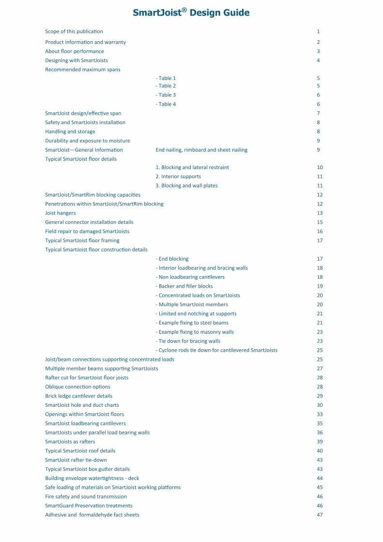
Scope of this publication 1
Product information and warranty 2
About floor performance 3
Designing with SmartJoists 4
Recommended maximum spans
- Table 1 5
- Table 2 5
- Table 3 6
- Table 4 6
SmartJoist design/effective span 7
Safety and SmartJoists installation 8
Handling and storage 8
Durability and exposure to moisture 9
SmartJoist—General Information End nailing, rimboard and sheet nailing 9
Typical SmartJoist floor details
1. Blocking and lateral restraint 10
2. Interior supports 11
3. Blocking and wall plates 11
SmartJoist/SmartRim blocking capacities 12
12 Penetrations within SmartJoist/SmartRim blocking
Joist hangers 13
General connector installation details 15
Field repair to damaged SmartJoists 16
Typical SmartJoist floor framing 17
Typical SmartJoist floor construction details
- End blocking 17
- Interior loadbearing and bracing walls 18
- Non loadbearing cantilevers 18
- Backer and filler blocks 19
- Concentrated loads on SmartJoists 20
- Multiple SmartJoist members 20
- Limited end notching at supports 21
- Example fixing to steel beams 21
- Example fixing to masonry walls 23
- Tie down for bracing walls 23
- Cyclone rods tie down for cantilevered SmartJoists 25
Joist/beam connections supporting concentrated loads 25
Multiple member beams supporting SmartJoists 27
Rafter cut for SmartJoist floor joists 28
Oblique connection options 28
Brick ledge cantilever details 29
SmartJoist hole and duct charts 30
Openings within SmartJoist floors 33
SmartJoist loadbearing cantilevers 35
SmartJoists under parallel load bearing walls 36
SmartJoists as rafters 39
Typical SmartJoist roof details 40
SmartJoist rafter tie-down 43
Typical SmartJoist box gutter details 43
Building envelope watertightness - deck 44
Safe loading of materials on SmartJoist working platforms 45
Fire safety and sound transmission 46
SmartGuard Preservation treatments 46
Adhesive and formaldehyde fact sheets 47

SmartJoist Design Guide 1
200240 240 240 24034
34 34 34 34
44 40 51 70 90
300
34
40
SJ30051
300
34
51
SJ30070
300
34
70
SJ30090
300
34
90
SJ36058
360
38
58
SJ36090
360
34
90
SJ40090
400
34
90
SJ20044 SJ24040 SJ24051 SJ24070 SJ24090 SJ30040
This Design Guide and Load Tables assists in the selection of SmartJoists for most of the common structural arrangements met in domestic construction. The SmartFrame website (www.tilling.com.au) and SmartFrame software, in conjunction with this manual, provides an unparalleled level of design capacity for SmartFrame engineered timber products. While specific details are given on suitable methods of developing lateral restraint, the methods of providing adequate support, ade-quate anchorage against wind uplift and overall structural stability are outside the scope of this publication. Information on the above matters can be obtained from AS1684 Residential timber-framed construction code or from a structural engineer experienced in timber construction. Tilling Timber Pty Ltd has structural engineers on staff who can be contacted for advice on matters concerning the use of its engi-neered timber products in timber construction on the Tech Sup-port Customer Helpline on 1300 668 690 or at [email protected]. Substitution of other products All load tables in this document are designed using in-grade tested properties for SmartJoists as manufactured by Pacific Woodtech Corporation of Washington State, USA. Other manufacturers I-Joists may have different properties and, therefore, cannot be designed using these span tables. Copyright
Copyright of this publication remains the property of Tilling Timber Pty Ltd, and reproduction of the whole or part of this publication without written permission from Tilling Timber Pty Ltd is prohibit-ed.
Certification As a professional engineer, qualified and experienced in timber engineering, I certify that the use of the SmartJoist members as shown in these tables, and installed in accordance with the provi-sions of this Design Guide, will comply with the requirements of the Building Code of Australia. These span tables have been pre-pared in accordance with standard engineering principles, the relevant test reports and Australian standards, i.e. -
AS 1684.1 Residential timber-framed construction
AS 1170.1 Structural Design Actions – Permanent Imposed and other actions
AS 1720.1 Timber Structures - Design Methods
AS 4055 Wind loads for Houses
ASTM D 5055 Standard specification for establishing and monitoring structural capacities of prefabricated wood I-Joists
Craig Kay RPEng, EC-1961, RPEQ-5100, BPB0730, CC5635 C, NER
Engineering Manager
Scope of this publication
Flange width 40, 44, 51, 58 , 70 and 90 mm web thickness : 9.5 mm, for 40, 44, 51, 58 ,and 70 mm flanges: 11.5 mm for 90 mm flanges
SmartJoist dimension tolerances: depth: + 0 -3 mm, Flange width: +/- 1 mm, flange thickness: no plus limitation -2 mm.
SmartJoist sizes available in each state may vary from time to time. Check you local stockist before ordering
The information contained in this product brochure is current as at Sept 2016 and is based on data available to Tilling Timber Pty Ltd at the time of going to print. Tilling Timber Pty Ltd has used its reasonable endeavours to ensure the accuracy and reliability of the information contained in this document and, to the extent permitted by law, will not be liable for any inaccuracies, omissions or errors in this information nor for any actions taken in reliance on this information. Tilling Timber Pty Ltd reserves the right to change the information contained in this document without prior notice. It is important that you call the Tech Sup-port Customer Helpline on 1300 668 690 to confirm that you have the most up to date information available.

SmartJoist Design Guide 2
“The strength is in the engineering”
The SmartFrame Engineered Wood System is made up of:
World class engineered timber products:
1. SmartJoist
2. SmartLVL
3. SmartLam Glulam's
4. Tecbeam
5. CLT
Unique SmartFrame Structural Design, Detailing and Esti-mating Software
Full engineering support and technical advice from expe-rienced engineers and field staff free of charge on our unique Tech Support Customer Helpline 1300 668 690.
SmartJoists The strength is in the engineering:- Strong. Stiff. Reliable. SmartJoists are engineered for heavy performance. We start with ultrasonically graded LVL, bonded with exterior adhesive for more load carrying capacity. The webs are made from stable, strong Oriented Strand Board (OSB) for superior strength and consistent performance. SmartJoists are more uniform than solid sawn joists. They stay straighter and are manufactured with no camber, so there is no chance of crown down or upside down installation. They resist shrinking, twisting, warping and splitting for squeak resistant floors and quality roofs and ceilings. Holes may be easily cut in the web according to the tables on page 30, allowing ducts and utilities to be run through the joists. Pre-punched 40 mm knockout holes are provided in the web for small diameter services or wiring. Save Time and Money:- Because they weigh less than solid sawn joists, SmartJoists are easier to install, saving construction time and cost. Their greater load carrying capacity allows you to space them further apart, so it takes fewer to build the average floor or roof. And with five (5) depths from 200 to 400 mm, you will never
have to compromise your design. So whether your plans call for cantilever beams in balconies, cathedral roofs or high pitched roof slopes, SmartJoists are the perfect choice. An Environmentally Sound Choice:- In addition to being cost effective, SmartJoists are also an environmentally sound choice because they are made of a renewable resource – wood. So they are a better choice for building. SmartJoists have a certified Chain of Custody system to PEFC. SmartFrame Software:- Our unique SmartFrame design, detailing and estimating software offers you unparalleled design and esti-mating capabilities with engineered timber. You will get accurate designs for a wide variety of applications, printouts and joist lay-outs. Limitations of use - SmartJoists. SmartJoists are to be used in dry interior environments only, fully enclosed from exposure to exterior moisture. SmartJoists are suitable for subfloor applications provided that the subfloor space is ventilated as per the BCA requirements. This means that SmartJoists must not be exposed to environments where the equilibrium moisture content of the joist will exceed 18%. Tilling Timber will not guarantee SmartJoists that have been left ex-posed to the weather either prior to or during construction for more than 90 days. Detailing such as cladding or lining must be used in moisture lad-en environments (commercial kitchens, bathrooms, wet industri-al areas, saunas, swimming pool and spa rooms etc.) and con-structed in such a way as to prevent exposure of the SmartJoist to moisture. SmartJoists may be used in applications which are often exposed externally (gable ends, eaves, floor joists applications in elevated houses, cantilevered joists etc.) but must be sufficiently enclosed with a suitable cladding, lining etc. to completely prevent the exposure of the SmartJoist to moisture.
Tilling Timber guarantees that SmartFrame Engineered Timber products have been manufactured to exacting standards and are free from defects in workmanship and materials. At Tilling Timber, we take great pride in SmartFrame products, so if you bring to our attention prob-lems such as squeaks that you believe are caused by our products, we guarantee that a technical representative will contact you promptly to evaluate the issues and provide advice to help solve the problem Providing that any SmartFrame product is correctly designed, handled and installed, any problem caused by an unlikely defect will promptly be remedied at no cost to you. This guarantee remains valid for the expected life of your home.
Tilling Timber Pty Ltd 31-45 Orchard Street
Kilsyth Vic 3137 Priority call: 1300 668 690 e-mail: [email protected]
SmartFrame Consumer Product Warranty

SmartJoist Design Guide 3
The “feeling” that is identified when a person walks on a floor is very subjective. Some people want to feel a very stiff floor and others want some ”give” so that it softens the footing. When peo-ple say the floor “bounces”, it may be vibrating. This sensation is often caused by lack of dead load such as furniture, direct applied ceilings or other materials to absorb or dampen the vibration. The AS 1684.1–1999 standard introduced a 1.0 kN static load ap-plied at mid-span as a serviceability equation to simulate the foot force effect on the design of floor joists. The differential deflection caused by this 1 kN load is limited to 2 mm. This criteria was developed for solid section floor joists up to 6 m spans, and in some cases, experience is now showing that at the 2 mm limit, the floor performance of lightweight I-Joist floors (especially without ceilings below e.g. subfloors) may be consid-ered unfit for purpose by some people. The two (2) alternative SmartJoist Span Table shown in this manual have been designed to meet the strength and serviceability criteria of:
Table 1 - AS 1684.1–1999 In this table the strength and serviceability limits of AS 1684.1 - 1999 have been used along with the recom-mended dynamic require-ments.
Table 2 - SmartJoist Pre-ferred Dynamics. In this table the strength and ser-viceability limits of AS 1684.1 - 1999 have been supplemented with a EN 1995-1-1-2004 serviceability equation to better model foot force effects on I-Joist floors. This approach has been demonstrated to produce stiffer floors for those wanting a firmer feel in their timber floor.
Both tables list MAXIMUM recommended joist spans, and there-fore shorter spans in most cases should produce stiffer floors. Factors that can affect floor dynamic performance
The choice of flooring system
The depth, stiffness and mass of the joists
Spacing of joists
Fixing of sheathing to joists
Stiffness and mass of floor sheathing
Mass and stiffness of ceiling materials
Method of installation
Location and type of internal partitions and furniture
Factors that can improve floor dynamic performance
Glue/nailed and glue/screw floors will perform better than floors secured by nails alone.
Deflection of the sheathing material between joists can be reduced by decreasing the joist spacing or using a thicker and/or stiffer sheathing.
Proper installation is essential for dependable per-formance. Adequate and level support for the joists is necessary, as is correct fastening of the joists and sheathing.
The installation of a ceiling to the bottom flange of the joists or a similar mass/loading sharing system.
While between joist blocking has been traditionally used to pro-vide some improvement to floor dynamic performance of solid timber joists, both testing and long experience show limited if any
improvement to the dynamic performance by midspan blocking of I-Joist floor systems with simple blocking. If floor dynamic perfor-mance is a concern to either the client, design-er or contractor, then the above variables can be altered, or additional methods be incorpo-rated to improve dynam-ic performance. Further information on the dynamic perfor-mance of lightweight timber floors can be obtained by calling the Tech Support Customer Helpline on 1300 668 or
at [email protected]. Large area ceramic tiled floors The modern trend to large size ceramic tiles has introduced a new design challenge for all floor substrates. Smaller numbers of grout-ed joins between larger tiles means that any deflection of the floor has to be larger per grouted joint, thus increasing the probability of cracking. AS 3958.1—2007 (incudes amendment 1-2010) Ceramic tiles Part 1: Guide to the installation of ceramic tiles limits the total deflec-tion of the floor (Dead Load + Live Load ) to L/360. This supple-mentary deflection limit is not one that is normally considered in the design of timber floors. The spans listed within Tables 2-4 meets the additional AS 3958.1—2007 Ceramic tiles Part 1: Guide to the installation of ceramic tiles deflection limits.
General information - about floor performance

SmartJoist Design Guide 4
SmartJoist Code
Depth (mm)
Flange width (mm)
Flange Thickness
(mm)
Web thickness
(mm)
Self weight (kg/m)
Moment (kN.m)
Shear (kN)
EI x 106 (kN.mm2)
GJ x 106 N.mm2)
GAw x 106 (N.mm2)
End reaction
(kN)
Max interior reactions
42 mm bearing (kN)
90 mm bearing (kN)
SJ20044 200 44 35 9.5 2.67 10.0 10.5 355 997 1.78 8.60 14.7 19.64
SJ24040 240 40 35 9.5 2.75 11.1 13.1 499 907 2.27 8.60 14.7 19.64
SJ24051 240 51 35 9.5 3.21 14.5 13.1 635 1156 2.27 9.48 17.0 22.43
SJ24070 240 69 35 9.5 3.98 19.8 13.1 852 1564 2.33 11.22 20.5 25.11
SJ24090 240 90 35 11.5 5.09 25.8 16.2 1066 2017 2.27 12.10 25.7 33.17
SJ30040 300 40 35 9.5 3.12 14.4 17.0 844 907 3.01 8.60 14.7 19.64
SJ30051 300 51 35 9.5 3.58 18.7 17.0 1069 1156 3.01 9.48 17.0 22.43
SJ30070 300 69 35 9.5 4.35 25.6 17.0 1432 1564 3.01 11.22 20.5 25.11
SJ30090 300 90 35 11.5 5.54 33.3 20.7 1790 2017 3.01 12.10 25.7 33.17
SJ36058 360 58 38 9.5 4.42 28.3 20.9 1953 1683 3.67 11.23 21.4 24.1
SJ36090 360 90 35 11.5 5.98 40.8 25.2 2793 2017 3.66 12.10 25.7 33.17
SJ40090 400 90 35 11.5 6.28 45.9 28.3 3541 2017 4.23 12.10 25.7 33.17
Designing with SmartJoists®
The design information contained within this Design Guide is for the properties of SmartJoist® I-Joists only. Other manufacturers’ I-Joists may have different properties and therefore cannot be designed using this information. Characteristic properties Strength reduction factors The strength reduction factor for calculating the design capacities of structural members shall be taken from the table below, refer-enced from AS 1720.1 –2010
Duration of load
The duration of load factor k1 for strength is defined within clause 2.4 of AS 1720.1. The duration of load factor J2 for deflection is defined below.
Deflection (Bending deflection + shear deflection)
Bending deflection—use standard engineering formula Shear deflection - for a uniformly distributed load w, over a span L
Partial seasoning factor SmartJoists are a seasoned timber product, generally k4 equals 1. Where the SmartJoists are subjected to conditions in which the average moisture content for a 12 month period is expected to exceed 15%, the characteristic capacity shall be decreased. The value of k4 shall be the greater of: a.
b. Where EMC is the highest value of the annual moisture content (percent) that the timber will attain in service. Length and position of bearing The k7 bearing factor is defined is clause 2.4.4 of AS 1720.1
Load sharing Because of the reduced variability of strength values of SmartJoist compared to solid timber , the load sharing factor k9 = 1.0.
Stability The stability factor k12 is defined within Appendix E of AS 1720.1
2.8 Temperature For covered timber structures under ambient conditions, no modification for strength need be made for the effect of temper-ature (i.e., k6 equals 1.0) except that where seasoned timber is used in structures erected in coastal regions of Queensland north of latitude 25°S, and all other regions of Australia north of lati-tude 16°S, the strength shall be modified by a factor k6 of 0.9.
Application of SmartJoist as a structural member
Category 1 Category 2 Category 3
Structural members for houses for which
failure would be unlikely to affect an area greater than 25
m2; OR
secondary members in structures other
than houses
Primary structural members in structures
other than houses; OR
elements in houses for which failure would be likely to affect an area*
greater than 25 m2
Primary structural members in struc-tures intended to
fulfil essential services or post
disaster function
Strength reduction factor Ø *
0.95 0.90 0.80
* AS 1720.1:2010 Table 2.1
Dimensional tolerances:
Length ± 10 mm
Depth +0, -3 mm
Flange width ± 10mm
Flange thickness No plus limitation, -2
Treatment: options
H2s(standard) and H2 treatment to AS 1604.2 and AS 1604.4
Duration of action Bending and shear
Short term 1 day 1.0
Long term > 12 months 2.0
AwGw
wL
EI x
wLjy
8
2
384
5 4
2
70
10
153001
4
4
.k
EMC..k

SmartJoist Design Guide 5
In compiling the span tables in this manual, the requirements of the relevant Australian standards and codes along with established Industry standard design guidelines for Residential Construction have been followed. In particular, the following codes and references have been used:
AS 1684.1 Residential timber-framed construction
AS 1170.1 Structural design actions – permanent imposed and other actions
AS 1720.1 Timber Structures - design methods
AS 4055 Wind loads for houses
AS/NZS 4063 Characterisation of structural timber
ASTM D 5055 Standard specification for establishing and monitoring structural capacities of prefabricated wood I-Joists
Serviceability criteria:
Max dead load deflection - lesser of span / 300 or 15 mm (j2 = 2) Max live load deflection - lesser of span / 360 or 9 mm
Table 1 - AS 1684.1-1999 Floor dynamics criteria
1. Minimum floor Natural Frequency - 8 Hertz 2. Maximum differential deflection between joists of 2 mm under a concentrated load of 1.0 kN mid-span to simulate the foot force
effect on the design of floor joists.
Table 2 - SmartJoist preferred Floor dynamics criteria (modified Eurocode)
1. Minimum floor Natural Frequency - 8 Hertz 2. Maximum differential deflection between joists of: - 1.8 mm for spans ≤ 4200 mm - 1700/L1.1 for span ≥ 4200 mm under a concentrated load of 1.0 kN mid-span to simulate the foot force effect on the design of floor joists.
Recommended maximum spans for lightweight residential floors
Loadings: Permanent Loading G: self weight + 40 kg/m2 + 0.5 kPa of live load permanently applied, live load Q: 1.5 kPa or 1.8 kN point live load
General domestic - 1.5 kPa
Joist spacing (mm) 300 400 450 600 300 400 450 600
SmartJoist code Self weight
(kg/m)
Maximum floor joist span (mm)
Single span Continuous span
SJ20044 2.8 4650 4300 4050 3650 5300 4900 4750 4350
SJ24040 3.0 5100 4700 4550 4150 5800 5350 5200 4900
SJ24051 3.4 5400 4950 4800 4450 6200 5650 5500 5200
SJ24070 4.0 5700 5350 5150 4800 6600 6050 5900 5500
SJ24090 5.0 6100 5650 5500 5050 7000 6450 6300 5950
SJ30040 3.4 5800 5350 5200 4800 6600 6100 5900 5650
SJ30051 3.9 6150 5650 5550 5100 7000 6500 6250 5900
SJ30070 4.3 6600 6100 5900 5400 7500 6900 6700 6300
SJ30090 5.5 6950 6450 6300 5800 7950 7350 7100 6700
SJ36058 4.8 7150 6550 6350 5850 8150 7500 7250 6900
SJ36090 5.9 7700 7150 6950 6400 8850 8150 7900 7500
SJ40090 6.2 8200 7500 7350 6800 9400 8650 8400 7800
Joist spacing (mm) 300 400 450 600 300 400 450 600
SmartJoist code Self weight
(kg/m)
Maximum floor joist span (mm)
Single span Continuous span
SJ20044 2.8 4650 4100 3850 3450 5200 4600 4400 4000
SJ24040 3.0 5100 4500 4300 3950 5700 4950 4800 4450
SJ24051 3.4 5400 4750 4550 4200 6050 5300 5150 4700
SJ24070 4.0 5750 5100 4900 4550 6400 5750 5500 5100
SJ24090 5.0 6100 5400 5250 4850 6800 6100 5850 5400
SJ30040 3.4 5800 5050 4900 4550 6500 5700 5450 5050
SJ30051 3.9 6150 5400 5200 4850 6900 6050 5800 5300
SJ30070 4.3 6600 5700 5550 5200 7300 6450 6200 5750
SJ30090 5.5 6950 6100 5900 5500 7700 6900 6600 6100
SJ36058 4.8 7150 6200 6000 5650 7900 7000 6700 6200
SJ36090 5.9 7700 6800 6550 6100 8600 7600 7350 6750
SJ40090 6.2 8200 7200 6900 6500 9050 8100 7750 7150

SmartJoist Design Guide 6
Table 3 - SmartJoist –65 kg/m2 - grout and tiled floor
1. Minimum floor Natural Frequency - 8 Hertz 2. Maximum differential deflection between joists of: - 1.8 mm for spans ≤ 4200 mm - 1700/L1.1 for span ≥ 4200 mm under a concentrated load of 1.0 kN mid-span to simulate the foot force effect on the design of floor joists. 3. Total deflection of the floor (Dead Load + Live Load ) to L/360 as per AS 3958.1—2007 (incudes amendment 1-2010) Ceramic tiles
Part 1: Guide to the installation of ceramic tiles
Table 4 - SmartJoist –120 kg/m2 - 40 mm grout and tiled floor
1. Minimum floor Natural Frequency - 8 Hertz 2. Maximum differential deflection between joists of: - 1.8 mm for spans ≤ 4200 mm - 1700/L1.1 for span ≥ 4200 mm under a concentrated load of 1.0 kN mid-span to simulate the foot force effect on the design of floor joists. 3. Total deflection of the floor (Dead Load + Live Load ) to L/360 as per AS 3958.1—2007 (incudes amendment 1-2010) Ceramic tiles
Part 1: Guide to the installation of ceramic tiles
Recommended maximum spans for residential floors with ceramic tiles
Loadings: Permanent Loading G: self weight + 65kg/m2 + 0.5 kPa of live load permanently applied, live load Q: 1.5 kPa or 1.8 kN point live load
General domestic - 1.5 kPa
Loadings: Permanent Loading G: self weight + 120 kg/m2 + 0.5 kPa of live load permanently applied, live load Q: 1.5 kPa or 1.8 kN point live load
Joist spacing (mm) 300 400 450 600 300 400 450 600
SmartJoist code Self weight
(kg/m)
Maximum floor joist span (mm)
Single span Continuous span
SJ20044 2.8 4500 4100 3800 3450 5100 4550 4300 3900
SJ24040 3.0 4900 4500 4250 3900 5600 4850 4700 4400
SJ24051 3.4 5200 4700 4550 4150 5950 5200 5050 4600
SJ24070 4.0 5500 5050 4850 4500 6300 5700 5400 5000
SJ24090 5.0 5850 5350 5150 4750 6700 6000 5800 5350
SJ30040 3.4 5600 5100 4850 4500 6400 5600 5400 4950
SJ30051 3.9 5900 5350 5100 4700 6800 5950 5750 5250
SJ30070 4.3 6300 5750 5500 5100 7200 6400 6150 5700
SJ30090 5.5 6650 6100 5800 5450 7600 6800 6500 6050
SJ36058 4.8 6800 6200 5950 5500 7800 6900 6600 6100
SJ36090 5.9 7350 6800 6450 6000 8500 7550 7300 6700
SJ40090 6.2 7800 7100 6850 6350 8900 8000 7700 7100
Joist spacing (mm) 300 400 450 600 300 400 450 600
SmartJoist code Self weight
(kg/m)
Maximum floor joist span (mm)
Single span Continuous span
SJ20044 2.8 4000 3700 3550 3250 4700 4350 4150 3800
SJ24040 3.0 4350 4050 3900 3550 5100 4700 4550 4300
SJ24051 3.4 4600 4300 4150 3800 5400 5000 4850 4500
SJ24070 4.0 4950 4550 4400 4100 5800 5350 5200 4800
SJ24090 5.0 5200 4800 4650 4350 6050 5650 5500 5100
SJ30040 3.4 5000 4600 4450 4100 5850 5400 5250 4800
SJ30051 3.9 5250 4850 4700 4300 6150 5750 5550 5150
SJ30070 4.3 5600 5200 5000 4650 6500 6100 5950 5500
SJ30090 5.5 5900 5500 5300 4950 6900 6400 6250 5800
SJ36058 4.8 6050 5650 5450 5050 7100 6600 5450 5950
SJ36090 5.9 6500 6100 5900 5450 7600 7100 6900 6450
SJ40090 6.2 6950 6500 6250 5750 8100 7550 7300 6800

SmartJoist Design Guide 7
Recommended maximum spans for residential floors (cont’d)
Flooring: Spans are suitable for solid timber, particle board and ply flooring. Floor sheathing glued and nailed to the joists will improve floor rigidity. Where a heavy overlay material is to be applied, such as thick mortar bed tiled or slate floors, the permanent load allowance should be in-creased to 1.2 kPa. A reduction of joist spacing can be used to accommodate this extra permanent load. A satisfactory result can be achieved by adopting the maximum spans for 600 mm and 450 mm spacing but installing the joists at 450 mm and 300 mm spacing respectively.
Continuous spans: For beams which are continuous over two unequal spans, the design span and the "resultant span description" depend on the percentage difference between the two spans as shown below:
Effective span Resultant span description Span difference
10% max main span continuous
10 - 30% 1.1 x main span continuous
above 30% diff main span single
Main span Second span
span difference = (main span - second span)
X 100 (main span + second span)
SmartJoist Design /Effective span
Normal structural analysis uses the centreline representation of the member. The term “span” can be defined in a number of ways and these are defined as follows: Clear Span. This is the distance between the faces of any support. It is generally the one easiest to measure and read from the drawings
Nominal span/centre-line span. This is the distance between the centre of the supports. This span is used to determine bending moments and deflections for continuous spaning members
Design span/Effective span. This is the span used for single span members to determine the bending moment, the slenderness of bending members and the deflections. In NZS 3603 this is the dimension referred to as “L”, and is defined below.
Design span/Effective span is the distance between -
The centre of the bearing at each end of a beam where the bearing lengths have NOT been conservatively sized
The centre of notional bearing that have been sized ap-propriately, where the size of the bearing IS conservative.
Diagram (a) shows beam where bearings have been designed appropriately. The effective span is taken as the distance between the centre of each bearing area
Diagram (b) shows beam where bearings at each end have been oversized. (This is frequently the case for beams that bear onto brickwork or concrete walls where the thickness of the wall is in excess of the area required to give the beam bearing capaci-ty). To find the correct effective span: 1. Calculate the minimum
bearing required to carry the loads satisfactorily
2. Add minimum bearing length to “clear span” distance
Area of s up po rt requi red fo r beari ng
length o f o rigi nal b earing (overs ized)
Length o f ef fective b earing
Cl ear sp an (dis tan ce betw een fac e o f s upp orts)
Ef fective (design) span
Cl ear sp an (dis tan ce betw een fac e o f s upp orts)
Ef fective (design) span

SmartJoist Design Guide 8
Accidents can be avoided under normal conditions by following these guidelines: 1. Brace each joist as it is erected. Joists must be nailed to
supports and all hangers, blocking, rim joists. X - bridging at supports must be completely installed and properly nailed. (see general notes and details)
2. Brace the ends of cantilevers (overhangs) with closure panels, rim joist or x - bridging (see general notes and details)
3. Lateral brace the top flange of each joist, to prevent side-ways buckling or rollover which may occur under light construction loads, such as a worker and/or a layer of un-nailed sheathing. Fully installed permanent sheathing or temporary struts to the top flange of each joist (see
‘Typical SmartJoist floor framing’) can accomplish lateral bracing. Temporary struts must be nailed to a lateral re-straint at the end of bay such as a braced wall or tempo-rary (or permanent) sheathing nailed to the first 1200 mm of the joist at the end of the bay (see ‘Typical floor or roof framing’)
4. Permanent sheathing must be completely installed and properly nailed before additional loads can be placed on the system
5. The integrity and safe use of these products can be seri-ously impaired if they are damaged. Do not install any damaged products. Contact your SmartFrame repre-sentative or the Tech Support Customer Helpline on 1300 668 690 if any product damage is noted.
Do not allow workers or loads on SmartJoists until all blocking, hangers, rim joists, nailing and temporary bracing are installed as specified below. Serious acci-dents or injury can result from failure to follow these guidelines.
Safety Warning
Handling and storage of SmartJoists
SmartJoists should be stacked in the upright position to avoid any damage during handling or storage.
Store SmartJoists flat on a hard, dry surface
If surface isn't paved, the ground should be covered with a polythene film
Keep covered with waterproof material that allows bundles to "breathe"
Use bearers (bolsters) between the ground and the first bundle (4 metre max spacing)
Use 100 x 50 timber flat between bundles at same spacing as bolsters
Take great care to rewrap remaining material after opening bundles
Wood "grows" in thickness and depth when allowed to get wet....KEEP DRY!
Wood with high MC has short term reduction in Characteristic Strengths …. KEEP DRY!
Under NO circumstances are stored SmartJoists to be in contact with the ground.
Use bearers to keep stacked material away from damp surfaces. Align bearer vertically
Bearers at a maximum of 4000 mm centres

SmartJoist Design Guide 9
SmartJoists - General information
Start to e nail ap p rox imately 2/3 u p the side of th e f lan ge.
N ails sh o uld b e as f ar as prac tical f ro m the
end o f th e joist
Do N OT start toe nail in to th e c orner o f the flangeo r th e to p o f the flange.
MAXIMUM N ai l d iameter 3.15 mm
1. Except where otherwise noted, 30 mm minimum bearing is required at joist ends and 42 mm minimum bearing is required at intermediate supports.
2. Nail joists at each bearing with 2 of 3.15 Ф x 65 nails, using one each side placed 30 mm from the end to avoid splitting as per detail below.
3. SmartJoist blocking or SmartRim - face nail to bearing plate with 3.15 Ф x 65 nails at 150 mm centres. Nail rim joist to the end of the top and bottom flange of each SmartJoist with 1 off 3.15 Ф x 65 nail, use 1 off 3.75 Ф x 75 nail top and bottom with joists with 58, 70 or 90 mm wide flanges.
4. 17-19 mm SmartRim - toe nail to bearing plate with 3.15 Ф x 65 nails at 150 centres or 4.5 Ф x 75 nails at 300 centres. Nail rim to the end of the top and bottom flanges of each SmartJoist with 1 3.15 Ф x 65 nails.
5. Sheathing nailing to top flange (Joists must be fully braced be-
fore sheathing is nailed or screwed) is detailed below
Do not use nails or screws larger than those shown above when attaching sheathing to flanges of SmartJoists
Minimum nail spacing is shown above, maximum nail spac-ing is set by the flooring manufacturer, in absence of manu-facturers data, 300 mm centres
SmartJoists are manufactured with Douglas Fir (Oregon) flanges with OSB webs, both having a durability rating of class 4, which is the same rating as some Ash type Eucalypts. Untreated SmartJoists should not be used where the equilibrium moisture content is likely to remain above 18 % for an extended period. Untreated SmartJoists are suitable in the internal, fully protected, ventilated and the external above ground, protected zones of the structure as shown in appendix B of AS 1684. Untreated SmartJoist is not suitable for external above ground, exposed or humid in-door conditions, such as swimming pool enclosures.
Moisture effects on SmartJoists
SmartJoist is supplied WITHOUT any short term construction seal-er, but once framed into a structure may be exposed to the weath-er for a limited time (not greater than 3 months) without negative affect, BUT, it may exhibit some effects of this exposure. The wood fibre in SmartJoists, like all wood products, is hygroscop-ic, which means it has an affinity for water. The wood fibre in SmartJoist will readily take up and release moisture in response to changes in the local environment. Moisture exposure will lead to dimensional change. While the products will withstand normal exposure, excessive exposure during distribution, storage or con-struction may lead to dimensional changes that affect serviceabil-ity. These changes include twisting, bowing or expansion to dimen-sions to beyond the specified tolerance of the product in the “as-manufactured” condition. As an organic material, mold and mildew may grow on untreated
wood products if moisture is present. Prolonged periods of high moisture may also support the growth of wood decay fungi, which is another reason to follow proper methods of storage and han-dling of SmartJoists. The table below shows the moisture content of SmartJoists as a function of humidity. Wetting during construction may lead to temporary elevated mois-
ture content and dimensional changes. Once covered, the SmartJoists will ultimately dry and re-equilibrate to the ambient humidity conditions, but some expansion or swelling may remain after drying.
Durability and exposure to moisture
Moisture content of wood products %(1)
Relative Humidity % LVL Flange MC OSB web
10 1.2 0.8
20 2.8 1.0
30 4.6 2.0
40 5.8 3.6
50 7.0 5.2
60 8.4 6.3
70 11.1 8.9
80 15.3 13.1
90 19.4 17.2
(1). Approximate moisture content at 210C
Minimum single row fastener spacing into SmartJoist flanges
SmartJoist flange width Fastener type
and size 40 mm flange
44 mm flange
51 mm flange
58-70 mm flange
90 mm flange
Nails
2.8 x 60 75 75 50 50 50
3.15 x 60 100 90 75 75 75
Screws
9g x 45 150 150 75 75 75
10g x 50 150 150 100 75 75
M ini mu m nai l or sc rew sp ac ing f rom table
O ffset sec on d row o f n ails o rsc rew s

SmartJoist Design Guide 10
Tighter effective nail spacing may be obtained by offsetting nail rows a minimum of 12 mm and maintaining a 10 mm minimum edge distance.
7. All joists require lateral support at end bearings using blocking or rim material.
8. The top flanges must be kept straight within 10 mm of the true alignment.
9. All roof details are valid to a maximum angle of 35° (as per AS1684
10. All nails are steel nails complying with AS 2334 - 1980 Steel
nails - Metric series. Nail gun nails of similar length and diame-ter may be substituted for the above provided that they are manufactured with properties equivalent to the nails in the above code.
11. Install all hangers to the manufacturers installation instruc-tions, taking particular attention to the use of the correct nails. Never use clouts or brads.
12. Prescriptive code requirements for mid span blocking of solid timber joists are not applicable to SmartJoists.
SmartJoists - General notes (Cont’d)
Typical SmartJoist floor details
Blocking and lateral restraint General notes: SmartJoists designed and constructed as per this Design Guide do not require mid-span blocking. The exception to this is for light-weight subfloors where there is no lining to the underside of the joists. For more information on this topic, see page 3 ‘ABOUT FLOOR PERFORMANCE’. Blocking within a structure falls within two (2) quite distinct stag-es: Temporary or during construction blocking to prevent roll over of joists before the installation of floor sheeting.
Permanent blocking to provide resistance to racking loads through the floor diaphragm, transfer of vertical wall loads and to provide torsional resistance to the end of the joist.
The provision contained within AS1684 Residential timber-framed
construction code dealing with blocking for deep joists, is “during
construction” or “temporary” blocking, designed only to prevent
the roll over of the deep joists prior to the floor sheeting being
attached. This level of blocking can form a part of any overall
blocking system, but was never intended to provide the total
amount of racking resistance or vertical load transfer
requirements within this floor diaphragm.
The lateral bracing requirements of the structure, unless there is full blocking of exterior walls, must be calculated in each individu-al case. Advice on this matter is obtainable from AS1684 Residen-tial timber-framed construction code.
1.0 Joists bearing onto external walls
1.1 Loads at joist support connection The ends of floor joists that bear onto a support experience exter-nal loads other than the floor dead and live loads, as shown. Any I-Joist, with it’s small cross sectional area, needs to have its end bearing capacity considered as part of the design process.
Further, as a holistic approach to the consideration of the lateral stability of the complete structure, it is necessary to consider the availability of racking and shear resistance through the floor dia-phragm.
1. Racking and shear effects due to wind and earthquake loads
2. Vertical loads on joists due to upper wall, floors and roof.
3. Un- sightly deflec-tions in the edges of unsupported sheet flooring may be experienced if heavy items of furniture are placed close to sheet edges.

SmartJoist Design Guide 11
Typical SmartJoist Floor details (Cont’d)
1.2 Stages of blocking/bracing
1.2.1 Temporary (during construction) end blocking Temporary or during construction blocking of the ends of joists
over external wall must comply with the requirements as shown in
the “SAFETY WARNING” on page 6 and as shown in the “TYPICAL
SmartJoist FLOOR FRAMING” diagram on page 14.
This is summarised as:
Temporary struts, fastened to top of SmartJoist, connected back to braced supports.
Temporary floor sheeting nailed to the first 1200 mm of joists at the end of the bay, in combination with struts, if no connec-tion to a braced wall can be made.
1.2.2 Permanent end blocking/bracing
Permanent blocking (bracing) to be effective in providing ade-quate transfer of racking and shear loads through the floor dia-phragm must comply with the details as shown in “TYPICAL SmartJoist FRAMING” diagram on page 17. In essence, fully block the ends of all joists at their bearing point on external walls, as per one of the options shown in details F1- F4. This permanent blocking/bracing provides: 1. A satisfactory mechanism to transfer racking loads through
the floor diaphragm. 2. Vertical load transfer independent of the floor joist. 3. Support to the end of the floor sheeting (Platform floors
only). Heavily loaded furniture legs have been known to cause large deflections and even failures at the edges of sheet flooring.
4. Torsional restraint to the end of floor joists, improving the joists structural performance.
2.0 Interior supports
2.1 Ends of simple spans
Where SmartJoists are discontinuous over interior supports, install the temporary strut bracing as per “SAFETY WARNING” on page 8.
2.2 Continuous spans
Continuous joists over internal supports do not require blocking, other than the temporary top flange struts as shown in the “SAFETY WARNING” on page 8, except in the following circum-stances:
Load bearing walls bear onto the joists at their support. (Details F7 or F8 apply)
Shear resistance is required in internal walls (This is a func-tion of shear resistance, and is not related to the structural adequacy of the joist itself.)
3.0 Blocking and wall plates
Wall plates in the frame are required to transfer vertical loads into the support structure below. These wall plates may be supported at 450 or 600 mm ctrs, thus acting as a beam between supports, bending about its weaker axis. When concentrated loads act at the centre of this wall plate, the bending and deflection effects can be quite significant. The full blocking of external and load bearing walls, as shown in details F1-F4, can act as a beam trans-ferring these loads to the support structure below, thus reducing the beam effect of the wall plates. Unless there is a requirement for double wall plates for a reason OTHER than the beam effect between supports, walls blocked as per detail F1-F4 and general notes #2, #3, and #4 provide suffi-cient beam action to allow single wall plates.
Lo wer sto rey stud s
B loc kin g as per d etail F1 - F4 of th eSmartJ oist Design Gu id e.
Floo r sheet ing secu relyn ailed to bloc kin g
U pp er sto rey LOAD B EARIN G stu d s
Lo wer sto rey to p p late
SmartJ oist f lo or joists

SmartJoist Design Guide 12
SmartR im
Do or or win do w openin g
To p plate
To p plate
H min
2/ 3 H M ax
H
To p plateHole o f 40 mm or less
75m mMin
Min 2 x d 1
H d2 <d 1
The maximum allowable hole size for a SmartJoist/SmartRim shall be ⅔ of the rim board depth as shown below.
The length of the SmartJoist/SmartRim segment containing a hole shall be at least 8 times the hole size.
SmartJoist hole sizes and corresponding minimum length
SmartJoist/SmartRim Depth (mm)
Maximum allowable hole size (a) (b) (mm)
Minimum length of SmartJoist/SmartRim board segment (c) for the maximum allowable hole size (mm)
200 130 1050
240 160 1280
300 200 1600
360 235 1900
400 265 2100
Application Notes
1. Do not cut holes in SmartRim installed over openings, such as doors or windows, where the SmartRim is not fully supported, except that holes of 40 mm or less in size are permitted provided they are positioned at the middle depth and in the middle ⅓ of the span ( see note 5 for minimum hole spacing). 2. Field-cut holes should be vertically centred in SmartRim and at least one hole diameter or 150 mm whichever is less, clear dis-tance away from the end of the wall line. Holes should never be placed such that they interfere with the attachment of the rim board to the ends of the floor joist, or any other code-required nailing. 3. While round holes are preferred, rectangular holes may be used providing the corners are not over-cut. Slightly rounding corners or pre-drilled corners with a 25 mm diameter bit is recommended. SmartRim over an opening
Do not cut holes in SmartRim over an opening except for holes of 40 mm or less in size (see note 1).
SmartJoist/SmartRim near concentrated vertical load 4. When concentrated loads are present on the SmartJoist/SmartRim (loads not supported by any other vertical-load-carrying members such as squash blocks), holes should not be placed in the SmartJoist/SmartRim within a distance equal to the depth of the SmartJoist/SmartRim from the area of loading.
5. For multiple holes, the clear spacing between holes shall be at least two times the diameter of the larger hole, or twice the length of the longest rectangular hole. This minimum hole spacing does not apply to holes of 40 mm or less in diameter, which can be placed anywhere in the rim board (see note 1 for holes over open-ing) except that the clear distance to the adjacent hole shall be 75 mm minimum.
Multiple holes for SmartJoist/SmartRim
6. All holes shall be cut in a workman-like manner in accordance with the limitations listed above.
(a) These hole provisions do not apply to SmartJoist/SmartRim installed over openings such as doors or windows (b) The diameter of the round hole or the longer dimension of the rectangular hole (c) The lengths of the SmartJoist/SmartRim segment per wall line. For multiple holes, the minimum length of SmartJoist/SmartRim segment shall be 8
times the sum of all hole sizes
Penetrations within SmartJoist and SmartRim blocking
SmartJoist/SmartRim® Characteristic blocking capacities SmartRim®
SmartRim rimboard is an alternative solution to blocking with SmartJoists (either long length of cut to length) to support verti-cal and lateral wall loads as part of a floor or roof framing system. SmartRim is a 19 or 21 mm LVL (2 veneers are cross laminated for stability) and is sold in 3.6 m lengths, precision ripped to match the height of the SmartJoist range up to and including 360 mm. (400 mm SmartRim in QLD only). Fixing of rimboard is de-scribed in detail in SmartJoist—GENERAL NOTES item 3 on page 8 of this Design Guide. SmartRim has a joint strength group of JD4 on the wide face for nails, screws and bolts.
1. Vertical load capacity above is for instantaneous load conditions and must be multiplied by the appropriate k1 factor for load condition under consider-ation
2. Vertical load capacity above already includes the k12 factor for up to 400 mm depth as per clause I2.3 of AS 1720.1
3. Horizontal load capacity above is an instantaneous load condition, with the k1 for lateral bracing loads usually 1.0
4. The above horizontal load capacity is limited by the fixing of the SmartJoist /SmartRim to the frame and can ONLY be achieve if the fixing detail on page 8 of this SmartJoist Design Guide is strictly adhered to.
SmartJoist/SmartRim Characteristic capacity (see notes below)
Horizontal load transfer capacity (kN/m) (3) (4)
Vertical load capacity (kN/m) (1) (2)
SmartJoist SmartRim 6.9
29 21 6.9

SmartJoist Design Guide 13
Joist hanger selection The joist hangers below have been developed specifically for the flange widths for SmartJoists are manufactured using Z275 light-gauge steel, having zinc coating of 275 gsm (total weight). AS1684.2-2010 and AS1684.3-2010-Australian Standards for Resi-dential Timber Frame Construction stipulates a minimum Z275 steel for all sheet metal products used in an internal environ-ment. Other joist hangers may be used with SmartJoists but it is the responsibility of the specifier of these alternative joists hangers to ensure that:
i. they suit the SmartJoist flange widths and do not require any cutting or packing of the flanges
ii. they are manufacturer from Z275 light-gauge steel
iii. they have the adequate capacity for the antici-pated end reaction
Fixing of joist hangers
1. Hand driven nails - The joist hangers in the table below are supplied by Tilling Timber as part of a SmartFrame order with the manufacturer recom-mended nails. All holes are to be filled with the specified nails in order to achieve the stated hanger capacity.
2. Gun nails - While the use of gun nails may be common, unless the gun nails are of a minimum
40 x 3.33 diameter, the hanger capacities listed cannot be assumed
3. Screws—The equivalent number of 35 x 6 gauge bugle-head or wafer-head wood screws may be used in lieu of the supplied nails. Increased capac-ities can be achieved by using screws. Advice on the capacities of the joist hangers listed below with screws replacing the nails can be obtained by contacting the Tech Support Customer Help-line on 1300 668 690.
Corrosion protection The standard range of joist hangers made from Z275 light-gauge steel, having zinc coating of 275 gsm is adequate only for INTER-NAL applications in most corrosion environments, except areas that are classified as heavy industrial or those subject to high humidity (e.g. enclosed swimming pools) etc. Under these cir-cumstances, seek advice from experts as special protection will be required. Note: INTERNAL areas are those within the building envelope that are kept permanently dry. In areas outside the building envelope that are exposed to repeated wetting (EXTERNAL are-as), stainless steel products or equivalent should be considered. Some alternatives include hot dip galvanised or powder coated steel, which are not Tilling Timber stock items. For more detailed information contact the Tech Support Custom-er Helpline on 1300 668 690 or at [email protected].
Joist hangers
SmartJoist
face mount code
down hanger
capacity ΦkN *
face nails
nail size top mount
code
down hanger
capacity ΦkN *
face nails to support
top nails
nails to joist
nail size (mm)
Single joist face mounts Single joist top mount
SJ20044 20044F 6.2 8 3.75 x 40 20044T 4.8 2 4 2 3.75 x 40
SJ24040 24040F 7.8 10 3.75 x 40 24040T 4.8 2 4 2 3.75 x 40
SJ24051 24051F 7.8 10 3.75 x 40 24051T 4.8 2 4 2 3.75 x 40
SJ24070 24070F 7.8 10 3.75 x 40 24070T 4.8 2 4 2 3.75 x 40
SJ24090 24090F 7.8 10 3.75 x 40 24090T 4.8 2 4 2 3.75 x 40
SJ30040 30040F 9.3 12 3.75 x 40 30040T 4.8 2 4 2 3.75 x 40
SJ30051 30051F 9.3 12 3.75 x 40 30051T 4.8 2 4 2 3.75 x 40
SJ30070 30070F 9.3 12 3.75 x 40 30070T 4.8 2 4 2 3.75 x 40
SJ30090 30090F 9.3 12 3.75 x 40 30090T 4.8 2 4 2 3.75 x 40
SJ36058 36058F 10.9 14 3.75 x 40 36058T 4.8 2 4 2 3.75 x 40
SJ36090 36090F 10.9 14 3.75 x 40 36090T 4.8 2 4 2 3.75 x 40
SJ40090 40090F 10.9 14 3.75 x 40 40090T 4.8 2 4 2 3.75 x 40
Double joist face mounts Double joist top mounts
2/SJ20044 20044DF 6.2 8 3.75 x 40 N/A
2/SJ24040 N/A 24040DT
2/SJ24051 24051DF 7.8 10 3.75 x 40 24051DT 4.8 2 2 4 3.75 x 40
2/SJ24070 24070DF 7.8 10 3.75 x 40 24070DT 4.8 2 2 4 3.75 x 40
2/SJ24090 24090DF 7.8 10 3.75x40 24090DT 5.7 2 4 2 3.75 x 40
2/SJ30040 N/A N/A
2/SJ30051 30051DF 8.7 12 3.75 x 40 30051DT 4.8 2 2 4 3.75 x 40
2/SJ30070 30070DF 8.7 12 3.75 x 40 30070DT 4.8 2 2 4 3.75 x 40
2/SJ30090 30090DF 8.7 12 3.75 x 40 30090DT 5.7 2 4 2 3.75 x 40
2/SJ36058 N/A 36058DT 4.8 2 4 2 3.75 x 40
2/SJ36090 N/A 36090DT 5.7 2 4 2 3.75 x 40

SmartJoist Design Guide 14
Joist hangers
Example specialised brackets/connectors Internal Flange Hangers - A range of internal flange hanger is available to suit ‘L’ shape connections and the edge joist in SmartJoist cassette floors
SmartJoist rafter brackets - Access is available to a range of rafter brackets especially designed to make use of the exceptional strength to weight ratio of SmartJoists and apply it to roof member applications. Rafter brackets available include: 1. Variable slope rafter con-
nectors 2. Variable slope and skew rafter connectors 3. Variable ridge connectors
Heavy duty roof beam supports - Tilling Timber has access to a range of heavy duty support brackets for all applications includ-ing brackets especially designed to cater for supported beam at a wide range of angles. An example is the Pryda® BBT125240 shown below
Individual designs - There are occa-sions where a generic off the shelf bracket is available for a particular application. In certain circumstances, Smart-Frame engineers may be available to
provide individual designs on a fee for service basis for users of SmartFrame product. (conditions apply)
For more detailed information contact the Tech Support Custom-er Helpline on 1300 668 690 or at [email protected].
Co nc ealed tabs toal low flu sh fix ingan d n eat "L " co nn ecti on s e. g.balco ny beams
Specialised joist hangers A range of more specialised joist hangers are available from Tilling Timber, some will be stock items and others will have a lead time before they could be supplied. Specifiers of these more specialised brackets should contact Tilling Timber during the design phase of the project to ascer-tain:
1. What brackets are available that would best suit the
proposed application 2. The lead time before selected joist hangers could be
supplied 3. Whether SmartFrame engineers are required to design
individual member connections
plan
Front
12 mm galvansied b olt with 50 x 50 x 3 mm galvan ised wash er
100 x 100 x 6 mmGalvan ised angle
Min 60 mm
Min 50 mm
Min 60 mm

SmartJoist Design Guide 15
General connector installation details
The top f lange of the supporting joist must be supportedby backer blocks to prevent cross grain bending and rotation.
Prevent rotation
D60%of D MIN
Positive angle nailing Top mount hangers
Correct fasteners
SmartJoist headers
Top mount connection
Face mount connection to web
Backer blocking each side, hanger nails must extend past thesupporting joist's web member into the backer blocking.
Hangers provide some joist rotation resistance; however, additional lateral restraint may be required for deep joists.
Bottom f lange pulling off when Backer block on one side only.
No web resistance Results in rotation
No web stif fener requiredHanger side flange supportsjoist top flange.
Web stiffener requiredHanger side flange should beat least 60% of joist depth orpotential joist rotation must beaddressed.
Correct nailing Nail at wrong angle Nail too long Hanger overspreadIf hanger is overspread, I-Joistmay be raised above header, also, NO support for top flange.
Hanger not plumbA hanger kicked out fromthe header can causeuneven surfaces.
Bracket capacities are based upon using the correct bracket nail as per the table on page 11. Bracket nails have special heads to provide strength. Clouts, brads etc are NOT suitable as bracket nails

SmartJoist Design Guide 16
Flange damage
Flange damage becomes more critical the nearer it is to mid-span or an interior support. Flange damage is less critical in close proximity to an end support.
How much flange damage is acceptable? A rule of thumb is "If you have to ask, it's too much". A saw kerf that knicks the cor-ner of a flange on one lightly-loaded joist could well be accepta-ble.
A joist with unacceptable flange damage cannot be repaired, rather a new joist must be added to take it's place. The dam-aged joist does not have to be removed. Consult SmartJoist and SmartLVL tables to find an acceptable new joist that is shallower than the damaged joist so installation is easier. Consider double and triple joists. If the damaged joist is multi-span, the new joist only needs to go across the span(s) where the damage occurs.
A single damaged joist can sometimes be trimmed off of adja-cent undamaged joists (run a calculation within the SmartFrame software).
Web damage
Web damage becomes more critical the nearer a support. Web damage is less critical near mid-span.
Web holes can be too big to repair. A flange-to-flange rectangu-lar hole longer than 450 mm located at mid-span probably war-rants a new joist. A 150 mm round hole located right by a sup-port probably warrants a new joist. Consult SmartJoist and
SmartLVL tables to find an acceptable new joist that is shallower than the damaged joist so installation is easier. Consider double and triple joists. If the damaged joist is multi-span, the new joist only needs to go across the span(s) where the damage occurs.
A single damaged joist can sometimes be trimmed off of adja-cent undamaged joists (run a calculation within the SmartFrame software)
Damage that could be confidently repaired in a single, isolated joist, might be judged too severe to repair if several, adjacent joists are involved
If several small holes violate the 2x diameter proximity rule, but would fit inside a single acceptable hole, then the group of small holes is OK
Hole repairs generally require a reinforcement that covers the full depth of the web and extends at least 300 mm past each side of the hole.
Damage report information required
1. In order to design a repair, the SmartFrame engineer will have to know all of the design information that is required to run SmartFrame software.
2. Provide a sketch of the damage showing it's size, shape and location on the joist.
3. Indicate whether a pipe, duct, conduit, etc. must remain and be accommodated.
4. Indicate how many adjacent joists are affected in each case.
Don’ make holes with a hammer other than tapping out pre-punched knockouts
Don’t hammer on flanges and damage joist
Do not cut or notch flanges Do not overcut holes in web
Field repairs to damaged SmartJoist webs
SmartJoists are sophisticated Engineered Timber products, and must be treated accordingly. Damage to key components, while affecting only a small percentage of the cross section may be sufficient to render the SmartJoist unsuitable for the purpose. It is therefore recommended that damage to joists and the possibility of repair be referred to the Tech Support Customer Helpline on 1300 668 690 or at [email protected] for advice.
The SmartFrame system now includes the WebFix® (web rein-forcement) developed to be a rapid “repair” to webs where penetrations have been placed at inappropriate locations, penetrations too large or other web damage which diminishes the strength of the member. This repair system is unique to SmartJoist applications. Tilling Timber is the SOLE Australian distributor of this PATENT-ED system, which in most cases can be fixed around services that have been installed through the web penetrations. The WebFix® does need to be designed into each situation by SmartFrame engineers and can ONLY be purchased from Tilling offices after the structural design is completed.
Field repair to damaged SmartJoists

SmartJoist Design Guide 17
Typical SmartJoist floor framing
Typical SmartJoist floor construction details
Sm artJoi stb loc kin g
p anel
Sm artJoi strim joist
NO TE:To p p late w idth m us t b e greaterth an wid th of flan ge rim j ois t +
30 m m (m in b earing length)
Solid b lo ck al l p osts fro m ab ove to
beari ng bel ow .
Sm al l sectio n of bearer m aterial
p lac ed on stump s/p iers to
su pp o rt joists su pp orting parall ello ad-bearin g w all s.
Lo ad -bearin g w all
Joists
Bearer
19 m m thic kSm artRimrim b oard
Bu tt sec tion s togetherat cen tre of low erstorey stu d.
2 layers of19 m m thic kSm artRimRi mb oard
Si ngl e/Upp er s torey
Lo wer storey o f tw o sto rey
Fi x ri mb oard w ith1/ 3.1 5 mm d ia. x 6 5 n ail into top & bo tto m flan ges
Fix r imbo ard into
to p & bo tto m p lates 30 mm in andat 45 d eg an gle with60 x 3.15mm n ail @ 150mm c trs
30
Fi x b otto m platew ith 90 x/3 .15 mmn ails @ 150 crs in tofloo rin g
Note: To achieve the necessary racking resistance through the floor diaphragm, it is important that the nailing provisions of the floor sheeting to the joists as described in AS 1684 (AS 1869 for particle board) be adopted to nail the floor sheeting to the Rim Joist or SmartRim in details F1-F3
Temp orary stru ts at 24 00 m m cen tres . Nail struts at eac h j ois t w ith
2 of f 3.15 x 65 mm n ai ls
M ultiple m em ber lamin ati on
Stand ardSm artJoi st
hangers
Rafter cu ts
Multip leSm artJoi sts
Endblocking
options
Sm artJoi st l oad beari ng can tilevers
SmartJ oists sup p ort in gof fset lo ad bearin g w alls
Sm artJoi st to s teelco n nection s
N on -lo ad
beari ng canti levers
Brick led ge canti levers
F14 F26
F1
F2
F3
F4
F1 F2
F3
F4
F5
F5
F6
F7
F8
F9 F9A
F10
F11
F27
F21
F9B

SmartJoist Design Guide 18
Backer for cladding
attachment
Use double jo ists
under wall where
vertical l oad exceeds
2 9 KN/ m
90 X 45 F5
Cripple skew
nailed to both
flanges with
3 .15 x 65 nai ls.
2 mmLoad bearing wall
above must stack
over wal l below
SmartJoi st shall be desi gned
to support load bearing wall above when not s tacked over
wall bel ow.
NOTE: Detai l F7 with blocking panel is required for bracing walls .
SmartJoi st
bl ockingPanel
Non Load bearing wall
to a maximum height
of 24 00 mm
SmartJoi st b locking
A
Beari ng.MIN. 70 mm
Sect ion A-A
Nail to backer block &
joist wi th 2 rows of
3. 15 x 7 5 mm at 15 0
mm centres and clinch
A
Backer b lock - nai l with 2 rows of
3. 75 dia x 65 mm nail s at 15 0 centres
and clinch1. 5 x LL
Min F7 - Durable or
treated timber
(Uniform loads ONLY).
Non Load bearing wall to a
maxi mum hei ght of 24 00 mm
12 00 mm MIN.12 00 mm MAX.
SmartJoi st b locking
SmartJoi sts may be cantilevered up to 1 /3
of their back span.
L
Example: 3 600 mmExample 12 00 mm
L/ 3 MAX.
NOTE: SmartJoists
MUST be fully protected
from the weather
Uni form l oads ONLY
Addi tional nai ls at end the prevent rotation90 - 190 mm joi st - 6 nail s20 0 - 29 0 mm joist - 8 nails30 0 - 40 0 mm joist -10 nails
Typical SmartJoist floor construction details (cont’d)
Interior loading bearing and bracing walls
WARNING - Correct blocking for SmartJoists
Non load bearing cantilevers (balconies)
Example cantilever spans and minimum back spans for this detail are shown in the table on the next page
Green timber shall not be used under any circumstance
All blocking shall be carried out as per details F1-F3, with blocking to extend to both flanges and skew nailed with 3.15 Ф x 65 nails, one each side of top and bottom flange.
F6
F7 F8
F9
F9a
For cantilevered joists supporting load bearing walls see details C1-C4

SmartJoist Design Guide 19
Fi ller b loc k,n ail with 10 of
3.75 dia x 75 nails
B acker bloc k, n ai lwith 10 o f 3.75 dia x 75 nails.
N ail backer blo ck in gwith 10 o f 3.75 x 75 nails.
Backer b loc krequ ired on bo th side
To p -mou nth an ger
Fi ller b loc kin g
n ail with 10 of3.75 x 75 nai ls
Fi ller b loc kin g
As p er detai l F15 or F15A
F12b.2F12b.1
F12b.3
50 ±
50 ±
50 ±
50 ±2 ro ws of 3.75x75nailsat 150mm sp ac in gC lin ch ed
Sm al l Gap( 3mm ± )
50 ±
50 ±
50 ±
50 ± 2 ro ws of 3.75x75 n ailsat 150mm sp ac in g
C lin ch ed
Sm al l Gap( 3mm ± )
Sm al l Gap( 3mm ± )
2 ro ws of 3.75x75 n ailsat 15 0 m m sp acin gC lin ch ed
Tigh t F it50 ±
50 ±
50 ±
50 ±
50 ±
50 ±
2 ro ws of 3.75 x 75 nails at 150 mm s pac ing
*each en d* (O ffset n ails from op po site face b y 75 m m) Cl inch ed
Sm al l Gap( 3mm ± )
F12b.4
2 ro ws of 3.75x75nailsat 150mm sp ac in gC lin ch ed
2 ro ws of 3.75x75nailsat 150mm sp ac in gC lin ch ed
2 ro ws of 3.75x75nailsat 150mm sp ac in gC lin ch ed
Fo r 2/51mm 2/70mm 2/90mm & 3/SJs with 1/setdo wn joist attach ed
Fo r 2 /40 m m & 2 /44 mm SJsw ith 1/s etd ow n j ois t attach ed
So lid t imber o r L VL b eam
If the sid es of the hanger
d o n ot su pp ort the to p flange.Web stif fen ers as per Detai l F1 3 are requ ired.
Face-mou nth an ger
To p -mou nth an ger
Min . 1mm, max. 3mmgap to eliminate co ntactb etween hanger an d joistwhic h may c au se sq ueaks
Face-mou nth an ger
N ail backer blo ck in gwith 75 x 3.15mm n ails.R efer to tab le for n o. of n ails requ ired
Face mou nt or
u niversal hanger
Fi ller b loc kin gAs p er detai l F15 or F15a
Web st iff en ers requ ired forSJ 40090 jo ists as p er Detail F13
Backer b loc ko n b oth sid es
Sm al l Gap
Face mou nt oru niversal hanger
To p mou nt or
u niversal hangerSetd own or ch an ge in level
R efer to d etailF12b .3 or F12b .4
R efer to
d etail F12b.1
Refer to Detai l F1 2b .2
Backer b loc k
Fi ller b loc k
Cantilevered balconies as per detail F9 and F9A
Joist spacing (mm) 300 400 450 600 Cantilever material Cantilever material Cantilever Back span Cantilever Back span Cantilever Back span Cantilever Back span
H3 SmartLVL 15
150 x 42 1.0 1.5 1.0 1.5 1.0 1.5 0.9 1.4
170 x 42 1.2 1.8 1.1 1.7 1.1 1.7 1.1 1.7
200 x 42 1.4 2.1 1.3 2.0 1.3 2.0 1.3 2.0
240 x 42 1.7 2.6 1.6 2.4 1.6 2.4 1.5 2.3
300 x 42 2.1 3.2 2.0 3.0 2.0 3.0 1.9 2.9
H3 MGP 10
140 x 45 0.7 1.1 0.7 1.1 0.7 1.1 0.7 1.1
190 x 45 1.1 1.7 1.1 1.7 1.1 1.7 1.1 1.7
240 x 45 1.5 2.3 1.4 2.1 1.4 2.1 1.4 2.1
Loadings: Permanent Loading G: self weight + 40 kg/m2 + 0.6 kPa of live load permanently applied, live load Q: 2.0 kPa or 1.8 kN point live load , 1.5 kN/m acting at end of cantilever
Backer and filler blocks
Filler block and web stiffeners
NOTES : 1. Use plywood sheathing for web stiffen-
er with face grain parallel to long axis of the stiffener.
2. Filler blocks noted are for the general requirements of the details within this design guide.
3. Leave 3 mm gap between top of filler blocks and bottom of top flange.
SmartJoist code
Web stiffener material Recommended filler block stiffener nails
SJ20044 120x35 15x60 mm ply 4-3.15x65
SJ24040 140x35 15x60 mm ply 4-3.15x65
SJ24051 140x45 19x60 mm ply 4-3.15x65
SJ24070 150x58 LVL 2/15x60 mm ply 4-3.15x65
SJ24090 2/140x45 2/19x60 mm ply 5-3.15x65
SJ30040 190x35 15x60 mm ply 4-3.15x65
SL30051 190x45 19x60 mm ply 4-3.15x65
SJ30070 150x58 LVL 2/15x60 mm ply 4-3.15x65
SJ30090 2/190x45 2/19x60 mm ply 5-3.15x65
SJ36058 250x50 2/12x60 mm ply 5-3.15x65
SJ36090 2/240x45 2/19x60 mm ply 5-3.15x65
SJ40090 2/240x45 2/ ply 5-3.15x65
F10
F11
F12
F12a
F12b
F12c

SmartJoist Design Guide 20
Concentrated loads on SmartJoists
Multiple SmartJoist members (a) filler blocks
NOTE: 1. Web stiffeners are NOT required
at end bearing supports when span length are taken from the SmartJoist Design Guide, except where they are required to pre-vent rotation if the joist hanger dos not laterally restrain the top flange
2. Web stiffeners may be required at inner supports under concen-trated loads. Consult the appro-priate tables.
Small gap
( 3mm ± )
Nails, 4 off
3.15 x 65, clinched
Tight fit50 mm ±
50 mm ±
3 mm min. gap
Tight Fit
Concentrated load from GT,
TGT, lintel etc.
3 mm min. gap
Web stiffeners under concentrated loads are required as shown below for concentrated loads that exceed 6.5 kN ONLY.
F13
3mm gap
C on tin uo us fi ller bloc k
3. 75 x 7 5 n ail s at 15 0 m msp aci ng. (O ffset n ails fro m op po site face by 75 mm )
3m m gap m in .
3.75 x 75 nails at15 0 mm sp ac ing.
(O ffs et n ail s from op po site face by 75 mm )C on tin uo us fi ller bloc k
50 ±
50 ±
2 ro ws of 3.75x75nailsat 15 0m m sp aci ngC lin ch ed
50 ±
50 ±
2 ro ws of
3.75x75 n ailsat 15 0 m m sp aci ngC lin ch ed
2 ro ws of 3.75x 75 nails at 150 sp ac ing each end . (Offset nails fro m opp os ite face b y 7 5 mm ),
cl inc hed
Small gap( 3 m m ± )
Small gap( 3 m m ± )
M in. 3 m m gap M in. 3 m m gap
Fo r 2 /70 m m 2 /9 0m m & 3 /SJs(n ailed f rom b oth si des )
Fo r 2 /40 m m 2 /4 4m m & 2/ 51 mm
Fo r 2 /70 m m 2 /9 0m m & 3/ SJs (nailed fromb oth sides)
Fo r 2 /40 m m 2 /4 4m m & 2/ 51m m
Min . 20
Min . 30
Min . 20
Min . 20
Min . 75
2 ro ws of 3.75x75 n ails
at 15 0 m m sp aci ngC lin ch ed
Min . 20
Min . 20
Min . 20
Min . 20
Min . 75
2 ro ws of 3.75x 75 nails at 150 sp ac ing each end . (Offset nails fro m opp os ite face b y 7 5 mm ), cl inc hed
2 ro ws of 3.75x 75 nails at 150 sp ac ing each end . (Offset nails fro m opp os ite face b y 7 5 mm ), cl inc hed
F15a
F15b
(b) SmartJoist Multi Joist clips (MJC)
2 ply SmartJoist supporting concentrated loads F15c
The SmartFrame MJC is Australia’s first backer and filler free solution to join multiple SmartJoist members
SmartJoist Applications - Characteristic Concentrated loads (kN)
No of MJC’s Max incoming Concentrated Load
4 16.4
8 24.6
400
400

SmartJoist Design Guide 21
U B, UC o rCh an nelSect ion
Min bearinglength 35 mm
Rebate o f12 m m Max
3-4 m m gap b etw eento p o f w eb sti ffen er
an d top flange
Web st iff en er installedin co n tac t with b otto m
flan ge as per d etail F12
Ad eq uate lateral restrain tor altern atively , a 10 x 3 0 m m lon g type 17 sc rew tolo wer flange
Limited end notching at supports
The cutting of notches in the ends of joists may reduce the allowable end reactions of the SmartJoists. The amended end reaction capacities of SmartJoists with a 12 mm notch are as follows:
Without web stiffeners - 80% of allowable end reaction
With added web stiffeners (as per detail F13) - Full end reaction capacity.
Do not over cut flanges. Substantial reductions in capacity may occur if
flanges are over cut.
To maintain the end reaction capacities above, end flange notching is strictly limited to: 1. Notch depths NOT greater than 12 mm 2. Notches cleanly cut - NO over cutting 3. Notch length not to exceed more than 5 mm past the support.
Example fixing of SmartJoists to steel beams
(a) Top mount or universal hangers
(b) SmartJoist MJC (cont’d)
2 ply SmartJoist supporting regular loads
sh eet f loo ringC oach bo lts
Fi xin g p late b olted to s teel
o r C hann elU B, UC , PFC
sect ion Top mo un tjo ist han ger
Sm artJoi st Sm artJoi st
U B, UC o r ch an nel sec tio n
on e b rac ket nail in every ho leof th e jo ist hanger
Jo ist h an ger to match jo ist size
Packer s hot fas ten ed toweb to p reven t hanger to steel con tac t
b olt or sh ot fastenp late to steel su ff icient ly to
p reven t mo vementan d lateral d isplacement
F17
F16
F17a
SmartJoist Applications - Characteristic Regular loads (kN)
No of MJC’s Max incoming regular Load
2 8.2
4 12.3
400
400

SmartJoist Design Guide 22
Example fixing of SmartJoists to steel beams
U B, UC
or Ch an nel sect ion
Fi xin g p late to either be bo lted o r s hot fas ten ed toto steel preven t ANY mo vem en tan d l ateral dis placem en t
Face-Mou n t jo ist h an ger to match jo ist size.
Skew n ail to p flange to fixin g p late with2/3.15mm d ia x 65mm nails
Fixin g plates: size depend en t u po n steel b eam sizes, b ut no t less th an 25 mm b earin g o nto steel b eam.N ail secu rely to p ac kers
70x35 o r 70x 45
vertic al s oftwo od packer s hot fix edto th e steel web
Weld the to p- mo u nt hanger (steel top p late) on to th e top flangeo f th e UB , U C or PFC steel beam
(R ef er to details below)U B, UCor Ch an nel sect ion
To p -mou nt jo ist hanger to match jo ist size.
M ini mu m 3m m, maxim um 6 mm
sp ace to eli mi nate co ntact betweenhanger and steel w hi ch may c aus esq ueaks .
30 x6 gauge bu gle-heador wafer-head wo od screws
Plan View
Section A:A
Leg
size
20 m mAAPacker to p reven t joisth an ger tosteel co n tac t
The welding of top mount SmartJoist hangers to common steel sections (UB, UC etc. must be carried out strictly as follows: 1. Supporting steel section must be thoroughly cleaned to remove black scale, rust, paint etc. 2. Clamp top flange of bracket hard up against steel section 3. Apply fillet weld to lap joint with the minimum weld length of 20 mm with a leg size at least the thickness of the metal hanger (see
diagram above) 4. Commence weld pool away from the hanger steel to ensure penetration into supporting steel prior to penetration into hanger tab 5. Finish connections with anti-corrosive paint to achieve appropriate corrosion resistance 6. It is essential that welding is conducted under the guidance of an experienced welder
Welding to steel sections (not suitable for universal hanger)
F17b F17c
20 m m (MAX)
web notch to beth e m in neces saryfo r cl earanc e.
Min Bearin glength 4 5 m m
U B, UCor Ch an nel Sec tio n
Web st iff en er installedin co n tac t with b otto m
flan ge as per d etail F12
D/ 2 (Max)5 - 6 mm gap
Ad eq uate lateral restrain t or altenatively, 1/ No 10 x 3 0m m lon g type 17 sc rew
as sh own.May be reb ated as perdetai l F1 6
Ti mb er p ac ker,m ini mu m of 3 5 mmbeari ng to s teel an d SmartJo ist
Packer to b e secu rely
fasten ed to steel b eam
U B
Steel Beam
Sm artJoi st12 m mm axi mu m
rebate
Do n ot exceed mo reth an 5 m m past s up po rt.
D
2 of 3.15 x 65 mmskew nails, on e each sid e,
2/ 3 u p flan ge a m in imu m of 30 m m from the end
(b) Rebated into steel beam
F18
F18a
Jo ist han ger as perth is Des ign Gu ide
Fi xin g p lates: s ize depen dent up on Sm artJoi st and steel beam si zes , bu t n ot les s th an 25 mm b earingon to steel b eam
70 mm verticalso ftwo od p ac ker
at jo ist lo catio nsh ot n ailed to steel web
Fi ller b loc k depth mu stfi t all f ace mou n t n ailsMin imum 35mm th ick
Skew n ail to p flange to fixin g p late with2/3.15mm d ia x 65mm nails
Face-Mou n t
jo ist hanger to match jo ist size
Fi xin g p lates: s ize depen dent up on steel beam siz es,
bu t n ot les s th an 25 m m beari ng onto s teel beam(Fix back to packers)
Skew n ail to p flange to fixin g p late with2/3.15mm d ia x 65mm nails 70x35mm o r 70x45mm
vert ical so ftwo od p ac kersh ot fastened to th e steel web
(c) Face mounting to steel
F19
F19a
SmartJoist Design Guide 23
Example fixing of SmartJoists to steel beams (cont’d)
250U C or 310U C
Fixin g plate fix ed tosteel b eam with b o lts(As p er en g. sp ec )
Section AA
A
Horizo ntal p in e in f ro nt of vertic als310U C - 70x 45mm MGP10250U C - 70x 35mm MGP10
Fi xin g p late
310U C - 300x58mm LVL15250U C - 240x42mm LVL15
AVert ical p in e @ 450mm c tr against steel web310U C - 70x 45mm MGP10250U C - 70x 45mm MGP10
(c) Fixing to masonry walls
Mason ry an ch ors to en gin eers d esign an d i nstalled tom anu fac turer's recom m end ati ons .
B ric k o r mason ry wall
SmartL VL or simi larp late, d ep th to app ro xmatch jo ist depth .
Face-mou nt o ru niversal joist hanger
Mason ry an ch ors to en gin eers d esign an d i nstalled tom anu fac turer's recom m end ati ons .
B ric k o r mason ry wall
SmartL VL or simi larp late
To p -mou nt oru niversal hanger
Plywoo d packer
3.15x50 FH n ail s@ 15 0 c trs into w all plate
30x6 gauge b u gle-h eado r waf er- head wo o d screws
F19b
F20 F20a
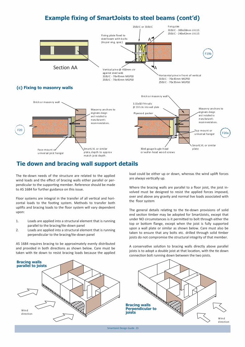
The tie-down needs of the structure are related to the applied wind loads and the effect of bracing walls either parallel or per-pendicular to the supporting member. Reference should be made to AS 1684 for further guidance on this issue. Floor systems are integral in the transfer of all vertical and hori-zontal loads to the footing system. Methods to transfer both uplifts and bracing loads to the floor system will vary dependent upon: 1. Loads are applied into a structural element that is running
parallel to the bracing/tie-down panel 2. Loads are applied into a structural element that is running
perpendicular to the bracing/tie-down panel AS 1684 requires bracing to be approximately evenly distributed and provided in both directions as shown below. Care must be taken with tie down to resist bracing loads because the applied
load could be either up or down, whereas the wind uplift forces are always vertically up. Where the bracing walls are parallel to a floor joist, the joist in-volved must be designed to resist the applied forces imposed, over and above any gravity and normal live loads associated with the floor system The general details relating to the tie-down provisions of solid end section timber may be adopted for SmartJoists, except that under NO circumstances is it permitted to bolt through either the top or bottom flange, except when the joist is fully supported upon a wall plate or similar as shown below. Care must also be taken to ensure that any bolts etc. drilled through solid timber joists do not compromise the structural integrity of that member. A conservative solution to bracing walls directly above parallel joists is to adopt a double joist at that location, with the tie down connection bolt running down between the two joists.
Tie down and bracing wall support details
Win d d irection
Win d d irection
Bracing walls parallel to joists
Bracing walls Perpendicular to joists

SmartJoist Design Guide 24
Seaso ned ti mb erbl ocking pi ece
B rac in g ( tie do wn ) wall M10 bo lt with 42mm L VL 15 tim b er b rid gin g c leat to ac hieve 6 .1 kN characteris tic u pli ft c ap ac ityo rM12 bo lt with 58mm L VL 15 tim b er b rid gin g c leatto ac hieve 8 kN ch arac teristi c u pli ft c ap ac ity
SmartJ oistat 45 0 m mctr m ax.
N ails to lo cate br idgin g c leatagain st top flange as sho wn
Refer to tab le b elo w forNo o f nails to ach ieve
th e requ ired d ow nward capacity
.
Sm artLV L15 tim b er bridging cleat. Cleats
to be pl aced n o c los erth an 1200 mm. R efer
to table b elow fo r t imber bridging cleat size
Braci ng (tie do wn ) w all
M12 bo lt
It is IMPO RTAN T that this b eam is nailed into joist h an gers top reven t joists spreadin g un der load
SmartL VL 15 timb er b rid gin g cleat.C leats to be plac ed no closer than 1200mm.
R efer to tab le below f or timb er br id gin g c leat size
17mm (min imum) F11 PlyMin of 170mm wide. N ai l with 4 of f 4.5 x 75 n ail s
an d clinc h. Fit flu sh u nd er to p flange o f Smart Jo ist
SmartJ oist
at 450mmctr max
Jo ist h an gers(b oth up an d d own) with
galvan ised t imber co n necto r n ai lsin to web sti ffeners/joist web & timb erb rid gin g cleat (R eferto table below f or N o o f nails req uired )
Do not drill through either flange of SmartJoists unless they are fully supported on wall plate or similar
Downward force capacities
Timber bridging size (DxB mm)
No of nails through
SmartJoist web to bridging
Characteristic capacity (kN)
1.2G + Wdn
90x42/58 SmartLVL 15 2 4.0
130x42/58 SmartLVL 15 3 4.9
170x42/58 SmartLVL 15 4 5.8
Timber bridging size (DxB mm)
Hanger code
No of hanger
nails into joist
No of hanger
nails into bridging
Characteristic uplift and
downward capacity (kN)
90x58 SmartLVL 15 FB5890 8 4 9.6
130X58 SmartLVL 15 FB58120 12 6 13.6
170X58 SmartLVL15 FB58170 20 10 20.0
F21
F21a
Tie down and bracing wall support details (cont’d)
Bracing walls between parallel joists
Bracing walls vertically above parallel joists
The tie-down and bracing of any structure is or critical im-portance to its robustness. While some general guidance on this topic is given in AS 1684 sections 8 and 9 including some specific examples, very little information is provided to designers where the bracing or tie down forces act within a floor dia-phragm, or how to transfer the design loads specified in table 8.18 to supporting members.
Below are some examples that may be helpful to designers utilis-ing SmartJoist floor joists but these examples must in no way be a substitute for expert engineering advice from an experienced structural engineer. Any member, especially tall slender sections typical of floor joists experience significant reduction in strength at the location of a vertical hole. Typically a vertical hole is deemed to have an effect of 1.5 times the diameter of the hole
Braci ng ( tie do wn ) w all
M12 bo lt at en d o feach p an el and in termed iately at Max at 1200 mm centres
SmartL VLat 450 mm
ctr m ax.
Dou ble jo istsu nd er paral lelb rac ing wall
15 m m deep n otc hin g o f d ou ble jo ists i s
p ermit ted O NL Y if a single u n- no tc hed joist
is struc tu ral ly adequ atein th is po sit ion
Do not drill through single members unless the whole member is re-analysed with a reduced cross
section at the hole location
F21c
B rac in g (t ie do wn ) wall
M12 bo lt at en d o feach p an el and in termed iately at M ax at 1 20 0 m m centres
SmartJ oistat 450 mm
ctr max.
1 piece of Min 35 mm timberh ard against b oth sides o f b olt, 50 mm wash er bearing on to b oth p ieces
Dou ble jo istsu nd er paral lel
b rac in g wall
40 mm high slo t inO NE web on ly
to allo w t igh tenin go f n ut
F21b

SmartJoist Design Guide 25
C yclon e rod
C yclon e rod , n ut an d w ash er u nd er top plate
Floo r sh eetin g
Web stif fen ersas per d etai l xx x
M ax dis tanc e f rom
cyclo ne rod to webstiffener of 100 m m.
Lo ad b earin g wal l
Pryda cyclon e strap o req uivalent
C yclon e rod , nu t and washer un der p lateSmartJ oist
b loc kin gp an el
Eq u al to can ti leversp an b ut MIN of 600 mm.
C an tileverSp an
Web st iff en ers requ ired each side o f ALL joists with cyclo ne ties
Cyclone strap capacities
Where the strap ends of the cyclone strap are wrapped around the wall plate or other timber member and are fixed with 4 of 3.15 Ø x 35 nails, the design capacity ØNj of 15.3 kN is applicable, regardless of the timber joint group. Tests have proven that bend-ing the legs of cyclone straps around the timber increases the ultimate load capacity.
While double joists shown in the above diagram, it is only necessary when loads exceed the capacities of single joist cantilevers.
Cyclone rod tie down for cantilevered SmartJoist floors
Joist/beam connections supporting offset load bearing walls
Modern building designs frequently call for the upper storey of a two storey dwelling to be set back from the lower wall to allow sufficient light access to all areas of the building. Provided that the SmartJoists have been designed to support this offset load, no special provisions need to be made for their support EXCEPT in the following support conditions:
Maximum Roof Area Supported (m2)
- based upon worst case of 40 mm flange width (conservative for wider flanged joists)
Joist supported on joist hanger RA1 Lower flange bearing RA2
Joist spacing (mm)
300 400 450 600 300 400 450 600 300 400 450 600 300 400 450 600
Joist span (mm)
Sheet Tile Sheet Tile
3500 21.7 15.0 12.8 8.2 9.6 6.7 5.7 3.6 6.9 6.4 6.2 5.3 3.1 2.9 2.8 2.4
4000 21.1 14.5 12.3 6.9 9.4 6.4 5.5 3.1 6.7 6.2 6.0 4.6 3.0 2.8 2.7 2.0
4500 20.5 13.9 11.7 5.7 9.1 6.2 5.2 2.5 6.6 6.0 5.7 3.9 2.9 2.7 2.5 1.7
5000 20.0 13.4 10.4 4.4 8.9 5.9 4.6 2.0 6.4 5.8 5.1 3.1 2.9 2.6 2.3 1.4
5500 19.4 12.1 9.1 3.2 8.6 5.4 4.1 1.4 6.3 5.3 4.6 2.4 2.8 2.4 2.0 1.1
U B, UCo r C hann el sect ion
B ric k o r mason ry wall
Jo ist h an ger to match jo ist size.
Lo ad bearin g w all
U B, UC o rC hann elSect ion
R eb ate o f12 mm Max
Min bearinglength 38 mm
Lo ad b earin g wall
CS1
RA1 RA2

SmartJoist Design Guide 26
Support for Concentrated loads - Joist/beam connection supporting off-set load bearing walls
Vertical laminations may be achieved by adopting the procedures described in clause 2.3 of AS1684, however these procedures should be considered as the minimum requirements to achieve the desired effect.
Experience with SmartLVL beams indicates that this degree of fixing may not satisfactorily prevent cupping of individual compo-nents as a result of the ingress of moisture between laminates during construction. The suggested method of vertical lamination below provides a greater level of fixity between individual compo-nents, and with the use of an elastomeric adhesive, also prevents moisture penetration between the laminates.
Multiple member laminating of top loaded beams (Symmetrical loading) The edges of the individual sections must be carefully aligned to each other so that the composite beam is flat, allowing the applied loads to be equally shared.
Depths up to and including 300 mm: 2 rows of nails as shown above at 300 mm centre
Depths in excess of 300 mm: 3 rows of nails as shown above at 300 mm centres.
Beams supporting SmartJoists – Multiple member laminations
M in of o ne M1 2 bol t every 12 00 mm c entres an d n ot less th an 3 b olts p er f iller bl ock sectio n, Mi n ed ge an d end dis tan ce o f 6 0 m m .
30 0m m deepSm artJoi st
Stud s o r po stssu pp orting Tru ncated Gird er tru ss or otherco nc entrated ro oflo ads
Skew nail 2 of 3.1 5 x 75 m m nails throu gh to l ow er p late
70 x 35 F5 nailed to un dersid e o f to p flan geof ad jac ent joi sts with3.15 x 60 nai ls
Web stif fen eras per d etai lF13
90 x 45 F5 st rut u nd erco nc entrated lo ad . Num ber of struts to match nu mb erof m em bers in jam b stu d o rp ost
M in bearin glength 5 8 m m
Rebate o f
12 m m Max
Stud o r p osts su pp o rtin g tru nc atedgird er tru ss or other co n cen trated roo f loads
Rebate as p er en gin eering sp eci ficatio n
U B,U C or PFCsect ion
So lid tim ber(SmartLV L1 5 o r si mi lar)Rebate as p er
en gin eering sp eci ficatio n
U B, UC o rC hann elSect ion
Face-mo un t or un iversaljo ist han ger to match jo ist siz e.
3 row s o f 3 .75 di a x 40 m m n ail sin to the web-s tiffener each sid e
Fi xin g p lates: s ize depen dent up on steel beam sizes, but no t less th an 25 mm b earing on to steel b eam(Fix back to packers)
250U B , U C o r PFC Section
Us e 1 0 / 40 x3 .75 mm galvanis ed nai lsHanger Desi gn Cap aci ty Dead + L ive Load = 7. 75 kNW in d U p lift = 5.6kN
30 x6 gauge bu gle-heador wafer-head w oo d screws
3 ro ws of 3.75 dia x 40 mm n ails in to the web
stiffener eac h s ide
70 x3 5m m or 7 0x 45 mmvertic al s oftwo od pac ker
fix ed to the steel w eb
Brick/m aso nry wall
Concentrated loads from any source such as girder trusses MUST be transferred through the floor space WITHOUT adding extra vertical loads to the ends of the SmartJoist at its bearing support. Examples of transferring these loads are shown below RA3 in-
volves the use of inclined timber struts as shown in the detail opposite. Struts must be a tight fit and at a minimum angle of 60º to the horizontal. RA4 uses a solid member in lieu of SmartJoist under large concentrated loads. RA5 involves a face fixing to blocked out steel beam.
RA3
RA4
RA5

SmartJoist Design Guide 27
Bead of elastomeric adhesive
Bead of elastomeric adhesive
Temporarywaterproofmembrane
300 mm spacing
D
Nails driven on alternate sides
300 mm spacing
Multiple member lamination of side loaded beams (Non– symmetrical loading)
50 mm Min
50 mm Min
50 mm Min
50 mm Min
55 mm diameterwasher as per table4.12 - AS 1720.1
Combination 1 Combination 2 Combination 32 pieces of 35 or 42 mm
3 pieces of35 or 42 mm
1 piece o f 35 o r 42 mm1 piece o f 58 o r 75 mm
Nail spacing
Bolt spacing
Stagger ro w of b olts
Maximum floor load width supported by either outside member (mm)
Combination (see details above)
3.75Ф x 90 mm nails 12 mm Ф bolts
2 rows at 300 ctrs 3 rows at 300 ctrs 2 rows at 600 ctrs 2 rows at 300 ctrs
Combination 1 3400 5100 7500 15000
Combination 2 2900 4000 5600 11000
Combination 3 2900 4000 4500 11000
Beams supporting SmartJoists – Multiple member laminations (Cont’d)
Notes: 1. Table values are for 40 kg/m2 floors.
2. The table values for nails may be doubled for nails at 150 mm centres, and tripled for nails at 100 mm centres
LB2
LB1
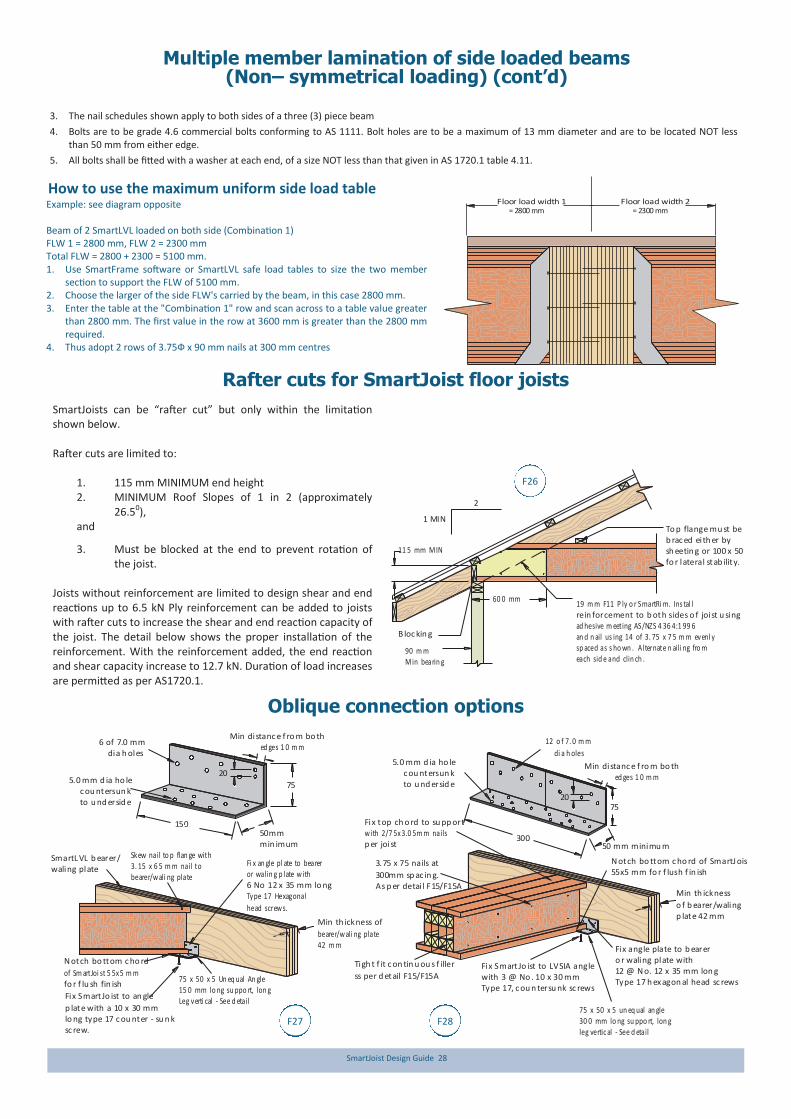
SmartJoist Design Guide 28
3. The nail schedules shown apply to both sides of a three (3) piece beam
4. Bolts are to be grade 4.6 commercial bolts conforming to AS 1111. Bolt holes are to be a maximum of 13 mm diameter and are to be located NOT less than 50 mm from either edge.
5. All bolts shall be fitted with a washer at each end, of a size NOT less than that given in AS 1720.1 table 4.11.
How to use the maximum uniform side load table
Example: see diagram opposite Beam of 2 SmartLVL loaded on both side (Combination 1) FLW 1 = 2800 mm, FLW 2 = 2300 mm Total FLW = 2800 + 2300 = 5100 mm. 1. Use SmartFrame software or SmartLVL safe load tables to size the two member
section to support the FLW of 5100 mm. 2. Choose the larger of the side FLW's carried by the beam, in this case 2800 mm. 3. Enter the table at the "Combination 1" row and scan across to a table value greater
than 2800 mm. The first value in the row at 3600 mm is greater than the 2800 mm required.
4. Thus adopt 2 rows of 3.75Ф x 90 mm nails at 300 mm centres
Floor load width 1= 2800 mm
Floor load width 2= 2300 mm
Multiple member lamination of side loaded beams (Non– symmetrical loading) (cont’d)
SmartJoists can be “rafter cut” but only within the limitation shown below. Rafter cuts are limited to:
1. 115 mm MINIMUM end height 2. MINIMUM Roof Slopes of 1 in 2 (approximately
26.50), and
3. Must be blocked at the end to prevent rotation of the joist.
Joists without reinforcement are limited to design shear and end reactions up to 6.5 kN Ply reinforcement can be added to joists with rafter cuts to increase the shear and end reaction capacity of the joist. The detail below shows the proper installation of the reinforcement. With the reinforcement added, the end reaction and shear capacity increase to 12.7 kN. Duration of load increases are permitted as per AS1720.1.
Rafter cuts for SmartJoist floor joists
Oblique connection options
60 0 mm
2
1 MIN
19 m m F11 P ly o r SmartRi m. Ins tal l rein forcement to b oth sides o f joist u singad hesive m eeting AS/NZS 4 36 4:1 99 6 an d n ail us ing 14 of 3. 75 x 7 5 m m evenl y sp aced as s ho wn . A lternate n aili ng fro meach sid e and clin ch .
B loc kin g
90 m mMin bearin g
To p flange mu st beb rac ed ei th er by sh eetin g or 100 x 50fo r lateral stab ility.
11 5 mm MIN
75 x 50 x 5 Un eq ual An gle15 0 mm lo ng su ppo rt, lon gLeg verti cal - See d etail
SmartL VL b earer/waling plate
Skew nail to p flan ge with3. 15 x 6 5 m m nail tobearer/w ali ng plate
Fix Smart Jo ist to an gle
p late with a 10 x 30 mmlo ng type 17 c ou nter - su n k sc rew.
Min th ickness of
bearer/w ali ng plate42 m m
Fi x an gle pl ate to beareror walin g p late w ith6 No 12 x 35 mm lo ngType 17 Hexagonal
head screw s.
N otch bo ttom c ho rd
of Sm artJoi st 5 5x 5 m m fo r f lu sh fin ish
Min distanc e f ro m bo th ed ges 1 0 m m
50mmmin imum
6 of 7.0 mm dia h oles
5.0 mm d ia ho le c ou ntersun k to u nd ersid e
20
Fix Smart Jo ist to LVSIA anglewith 3 @ No . 10 x 30 mm Type 17, c ou n tersu nk sc rews
N otch bo ttom c ho rd of SmartJ oist55x5 mm fo r f lush f in ish
Fix angle plate to b earero r waling plate with12 @ N o. 12 x 35 mm lon gType 17 h ex agon al head sc rews
75 x 50 x 5 un eq ual an gle30 0 mm lo ng su ppo rt, lon gleg vertic al - See d etail
Min th ickness
o f b earer/walingp late 42 mm
3.75 x 75 nails at
300mm sp ac in g.As p er detai l F15/F15A
Tigh t f it c on tin u ou s f iller
ss per d etail F15/F15A
150
75
50 mm minimu m
12 o f 7. 0 m m
di a h oles5.0 mm d ia ho le c ou ntersun k to u nd ersid e
300
75
Min distanc e f ro m bo th ed ges 1 0 m m
20
Fix top ch o rd to su pp ortw ith 2/7 5x 3.0 5m m nails p er joist
F26
F27 F28
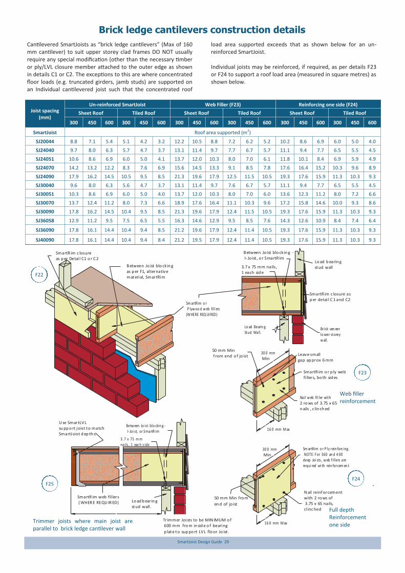
SmartJoist Design Guide 29
Brick ledge cantilevers construction details
Cantilevered SmartJoists as “brick ledge cantilevers” (Max of 160 mm cantilever) to suit upper storey clad frames DO NOT usually require any special modification (other than the necessary timber or ply/LVL closure member attached to the outer edge as shown in details C1 or C2. The exceptions to this are where concentrated floor loads (e.g. truncated girders, jamb studs) are supported on an Individual cantilevered joist such that the concentrated roof
load area supported exceeds that as shown below for an un-reinforced SmartJoist. Individual joists may be reinforced, if required, as per details F23 or F24 to support a roof load area (measured in square metres) as shown below.
Un-reinforced SmartJoist Web Filler (F23) Reinforcing one side (F24) Joist spacing
(mm) Sheet Roof Tiled Roof Sheet Roof Tiled Roof Sheet Roof Tiled Roof
300 450 600 300 450 600 300 450 600 300 450 600 300 450 600 300 450 600
SmartJoist Roof area supported (m2)
SJ20044 8.8 7.1 5.4 5.1 4.2 3.2 12.2 10.5 8.8 7.2 6.2 5.2 10.2 8.6 6.9 6.0 5.0 4.0
SJ24040 9.7 8.0 6.3 5.7 4.7 3.7 13.1 11.4 9.7 7.7 6.7 5.7 11.1 9.4 7.7 6.5 5.5 4.5
SJ24051 10.6 8.6 6.9 6.0 5.0 4.1 13.7 12.0 10.3 8.0 7.0 6.1 11.8 10.1 8.4 6.9 5.9 4.9
SJ24070 14.2 13.2 12.2 8.3 7.6 6.9 15.6 14.5 13.3 9.1 8.5 7.8 17.6 16.4 15.2 10.3 9.6 8.9
SJ24090 17.9 16.2 14.5 10.5 9.5 8.5 21.3 19.6 17.9 12.5 11.5 10.5 19.3 17.6 15.9 11.3 10.3 9.3
SJ30040 9.6 8.0 6.3 5.6 4.7 3.7 13.1 11.4 9.7 7.6 6.7 5.7 11.1 9.4 7.7 6.5 5.5 4.5
SJ30051 10.3 8.6 6.9 6.0 5.0 4.0 13.7 12.0 10.3 8.0 7.0 6.0 13.6 12.3 11.2 8.0 7.2 6.6
SJ30070 13.7 12.4 11.2 8.0 7.3 6.6 18.9 17.6 16.4 11.1 10.3 9.6 17.2 15.8 14.6 10.0 9.3 8.6
SJ30090 17.8 16.2 14.5 10.4 9.5 8.5 21.3 19.6 17.9 12.4 11.5 10.5 19.3 17.6 15.9 11.3 10.3 9.3
SJ36058 12.9 11.2 9.5 7.5 6.5 5.5 16.3 14.6 12.9 9.5 8.5 7.6 14.3 12.6 10.9 8.4 7.4 6.4
SJ36090 17.8 16.1 14.4 10.4 9.4 8.5 21.2 19.6 17.9 12.4 11.4 10.5 19.3 17.6 15.9 11.3 10.3 9.3
SJ40090 17.8 16.1 14.4 10.4 9.4 8.4 21.2 19.5 17.9 12.4 11.4 10.5 19.3 17.6 15.9 11.3 10.3 9.3
N ail reinf orcement with 2 ro ws of 3.75 x 65 nails,cl inc hed
30 0 mm Min
16 0 mm M ax
50 mm Min fro m
en d of jo ist
Leave smallgap ap prox 6 mm
30 0 mm Min
SmartR im o r p ly webfi llers, bo th sid es
16 0 mm M ax
50 mm Min f rom end o f jo ist
SmartR im c losureas p er Detai l C1 o r C 2
B etween Jo ist blo ckin gas p er F1, al ternativematerial, SmartRim
Sm artRim o r P lyw oo d w eb fill ers(WHERE REQ UI RED)
3.7 x 75 mm nails,1 each sid e
Lo ad Bearin gStud Wall.
B etween Jo ist blo ckin g - I- Jo ist , o r SmartR im
Lo ad b earin gstud wall
SmartR im c losure asp er detai l C 1 and C2
Brick ven eerlo wer storeyw all.
Nail w eb fil ler with 2 ro ws of 3.75 x 65n ails , c lin ch ed
SmartR im web fil lers ( WHER E REQU IR ED) Lo ad b earin g
stud wall .
Tr immer Joists to be MIN IMUM o f 600 mm fro m in sid e o f bearing
p late to sup po rt LVL flo or Jo ist .
U se SmartLVLsu pp o rt joist to matchSmartJ oist d ep th s.
Betw een Jo ist blo ckin g - I- Joi st, or SmartR im
3. 7 x 75 m m nails , 1 eac h s ide
Sm artRim o r P ly rein forc ing. NOTE: For 360 an d 4 00 deep Joi sts , w eb f illers are requi red wi th rein forcem en t
F22
F23
F24 F25
Web filler reinforcement
Trimmer joists where main joist are parallel to brick ledge cantilever wall
Full depth Reinforcement one side
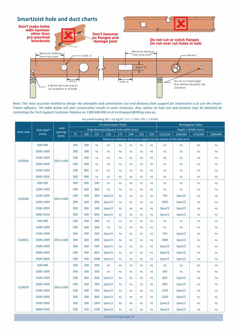
SmartJoist Design Guide 30
Don’t make holes with hammer
other than pre-punched
knockouts
Don’t hammer on flanges and damage joint Do not cut or notch flanges
Do not over cut holes in web
SmartJoist hole and duct charts
Min imum d istan cefrom h ole c hart
w idth 'w 'N ote 3
w idth 'w ' see n ote 7
A 40 mm dia h ole may b e cu t an ywhere in th e web
Dep th 'D'
Do n ot cu t ho les larger th an 40 mm d ia within thecant ilever
Min imum d istan ce f rom h o le c hart
Note: The most accurate method to design the allowable web penetration size and distance from support for SmartJoists is to use the Smart-Frame software. The table below will give conservative results in some instances. Also, advice on hole size and location may be obtained by contacting the Tech Support Customer Helpline on 1300 668 690 or at [email protected].
Assumed loading (DL = 62 kg/m2, FLL = 2 kPa, FPL = 1.8 kN)
Joist code Joist span*
(mm)
Circular/square holes Rectangular holes Joist
spacing (mm)
Hole diameter/Square hole width (mm) Depth x Width (mm)
75 100 125 150 175 200 225 250 125x150 150x300 175x350 200x400
Minimum distance from any support to the centre of the hole (mm)
SJ20044
600-999
300 to 600
300 300 ns ns ns ns ns ns ns ns ns ns
1000-1499 300 300 ns ns ns ns ns ns ns ns ns ns
1500-1999 300 300 ns ns ns ns ns ns ns ns ns ns
2000-2499 300 600 ns ns ns ns ns ns ns ns ns ns
2500-2999 300 800 ns ns ns ns ns ns ns ns ns ns
3000-3300 300 900 ns ns ns ns ns ns ns ns ns ns
SJ24040
600-999
300 to 600
300 300 300 ns ns ns ns ns ns ns ns ns
1000-1499 300 300 300 ns ns ns ns ns ns ns ns ns
1500-1999 300 300 300 Span/2 ns ns ns ns 750 Span/2 ns ns
2000-2499 300 300 300 Span/2 ns ns ns ns 1000 Span/2 ns ns
2500-2999 300 300 500 Span/2 ns ns ns ns Span/2 Span/2 ns ns
3000-3500 300 300 800 Span/2 ns ns ns ns Span/2 Span/2 ns ns
SJ24051
600-999
300 to 600
300 300 300 ns ns ns ns ns ns ns ns ns
1000-1499 300 300 300 ns ns ns ns ns ns ns ns ns
1500-1999 300 300 300 Span/2 ns ns ns ns 750 Span/2 ns ns
2000-2499 300 300 300 Span/2 ns ns ns ns 1000 Span/2 ns ns
2500-2999 300 300 500 Span/2 ns ns ns ns Span/2 Span/2 ns ns
3000-3499 300 300 800 Span/2 ns ns ns ns Span/2 Span/2 ns ns
3500-3800 300 300 1000 Span/2 ns ns ns ns Span/2 Span/2 ns ns
SJ24070
600-999
300 to 600
300 300 300 ns ns ns ns ns ns ns ns ns
1000-1499 300 300 300 ns ns ns ns ns 300 ns ns ns
1500-1999 300 300 300 Span/2 ns ns ns ns 600 Span/2 ns ns
2000-2499 300 300 300 Span/2 ns ns ns ns 900 Span/2 ns ns
2500-2999 300 300 500 Span/2 ns ns ns ns 1250 Span/2 ns ns
3000-3499 300 300 800 Span/2 ns ns ns ns 1500 Span/2 ns ns
3500-3999 300 300 1000 Span/2 ns ns ns ns Span/2 Span/2 ns ns
4000-4100 300 450 1100 Span/2 ns ns ns ns Span/2 Span/2 ns ns

SmartJoist Design Guide 31
SmartJoist hole charts (Cont’d)
Assumed load (DL = 62 kg/m2, FLL = 2 kPa, FPL = 1.8 kN)
Joist code Joist span*
(mm) Joist
spacing (mm)
Circular/square holes Rectangular holes
Hole diameter/square hole width (mm) Depth x Width (mm)
75 100 125 150 175 200 225 250 125x150 150x300 175x350 200x400
Minimum distance from any support to the centre of the hole (mm)
SJ24090
600-999
300 to 600
300 300 300 ns ns ns ns ns ns ns ns ns
1000-1499 300 300 300 ns ns ns ns ns 300 ns ns ns
1500-1999 300 300 300 700 ns ns ns ns 500 750 ns ns
2000-2499 300 300 300 1000 ns ns ns ns 800 1000 ns ns
2500-2999 300 300 400 1150 ns ns ns ns 1100 Span/2 ns ns
3000-3499 300 300 700 1400 ns ns ns ns 1400 Span/2 ns ns
3500-3999 300 300 800 1550 ns ns ns ns 1700 Span/2 ns ns
4000-4100 300 300 900 1600 ns ns ns ns 1800 Span/2 ns ns
SJ30040
600-999
300 to 600
300 300 300 300 300 300 ns ns 300 300 ns ns
1000-1499 300 300 300 300 300 300 ns ns 300 500 Span/2 ns
1500-1999 300 300 300 300 300 500 ns ns 300 Span/2 Span/2 Span/2
2000-2499 300 300 300 300 300 700 ns ns 500 Span/2 Span/2 Span/2
2500-2999 300 300 300 300 400 1000 ns ns 900 Span/2 Span/2 Span/2
3000-3499 300 300 300 300 600 1200 ns ns 1300 Span/2 Span/2 Span/2
3500-3999 300 300 300 300 900 1450 ns ns 1750 Span/2 Span/2 Span/2
4000-4100 300 300 300 400 1000 1500 ns ns Span/2 Span/2 Span/2 ns
SJ30051
600-999
300 to 600
300 300 300 300 300 300 ns ns 300 300 ns ns
1000-1499 300 300 300 300 300 300 ns ns 300 500 Span/2 ns
1500-1999 300 300 300 300 300 500 ns ns 300 750 Span/2 Span/2
2000-2499 300 300 300 300 300 700 ns ns 400 Span/2 Span/2 Span/2
2500-2999 300 300 300 300 400 1000 ns ns 800 Span/2 Span/2 Span/2
3000-3499 300 300 300 300 600 1200 ns ns 1200 Span/2 Span/2 Span/2
3500-3999 300 300 300 300 900 1450 ns ns 1600 Span/2 Span/2 Span/2
4000-4300 300 300 300 400 1000 1600 ns ns 1800 Span/2 Span/2 ns
SJ30070
600-999
300 to 600
300 300 300 300 300 300 ns ns 300 300 ns ns
1000-1499 300 300 300 300 300 300 ns ns 300 500 Span/2 ns
1500-1999 300 300 300 300 300 500 ns ns 300 750 Span/2 Span/2
2000-2499 300 300 300 300 300 700 ns ns 400 1000 Span/2 Span/2
2500-2999 300 300 300 300 400 950 ns ns 700 1250 Span/2 Span/2
3000-3499 300 300 300 300 600 1200 ns ns 1000 Span/2 Span/2 Span/2
3500-3999 300 300 300 300 900 1450 ns ns 1400 Span/2 Span/2 Span/2
4000-4499 300 300 300 500 1100 1700 ns ns 1800 Span/2 Span/2 Span/2
4500-4600 300 300 300 700 1200 1800 ns ns 1900 Span/2 Span/2 Span/2
SJ30090
600-999 300 300 300 300 300 300 ns ns 300 300 ns ns
300 to 600
1000-1499 300 300 300 300 300 300 ns ns 300 400 Span/2 ns
1500-1999 300 300 300 300 300 300 ns ns 300 750 Span/2 Span/2
2000-2499 300 300 300 300 300 600 ns ns 300 950 Span/2 Span/2
2500-2999 300 300 300 300 300 800 ns ns 500 1200 Span/2 Span/2
3000-3499 300 300 300 300 400 1100 ns ns 800 1500 Span/2 Span/2
3500-3999 300 300 300 300 700 1300 ns ns 1200 1750 Span/2 Span/2
4000-4499 300 300 300 300 950 1600 ns ns 1600 Span/2 Span/2 Span/2
4500-4900 300 300 300 500 1100 1800 ns ns 1800 Span/2 Span/2 Span/2

SmartJoist Design Guide 32
* Single span Notes: 1. The hole chart is generated for single span joists with a maximum floor dead load of 62 kg/m2 with no wall or roof loads. It therefore does not apply for
joists supporting either parallel or perpendicular load bearing walls. These scenarios can be analysed by using the appropriate model within the Smart-Frame software. Help can be obtained for continuous spans by contacting the Tech Support Helpline on 1300 668 690 or at [email protected]
2. Hole locations are suitable for joist spacings up to 600 mm centres. Holes may be permitted closer to supports for some member when spacings of 450 or 300 mm are used
3. The clear distance between holes must equal or exceed twice the diameter of the largest hole, or twice the longest side of a rectangular hole and no more than 3 holes in excess of 75 mm are allowed in any span
4. Do not cut or damage flanges under any circumstances 5. Except as noted in 1 and 2 above, a 40 mm hole at a minimum of 450 mm centres is allowed to be drilled anywhere in the web EXCEPT in cantilevered
spans 6. If possible, holes in web should be positioned mid height, minimum edge clearance from any flange is 6 mm 7. A group of round holes at approximately the same location shall be permitted if they meet the requirements for a single round hole circumscribed
around them.
Assumed load (DL = 62 kg/m2, FLL = 2 kPa, FPL = 1.8 kN)
Joist code Joist span
(mm)
Circular/square holes Rectangular holes
Joist* spacing (mm)
Hole diameter/square hole width (mm) Depth x Width (mm)
75 100 125 150 175 200 225 250 125x150 150x300 175x350 200x400
Minimum distance from any support to the centre of the hole (mm)
SJ36058
600-999
300 to 600
300 300 300 300 300 300 300 300 300 300 ns ns
1000-1499 300 300 300 300 300 300 300 300 300 300 400 ns
1500-1999 300 300 300 300 300 300 300 400 300 300 700 Span/2
2000-2499 300 300 300 300 300 300 300 700 300 550 900 Span/2
2500-2999 300 300 300 300 300 300 400 900 300 850 1200 Span/2
3000-3499 300 300 300 300 300 300 650 1200 300 1200 1500 Span/2
3500-3999 300 300 300 300 300 400 900 1400 300 1500 1750 Span/2
4000-4499 300 300 300 300 300 600 1100 1700 300 1800 Span/2 Span/2
4500-5000 300 300 300 300 300 800 1400 1900 300 2200 Span/2 Span/2
SJ36090
600-999
300 to 600
300 300 300 300 300 300 300 300 300 300 ns ns
1000-1499 300 300 300 300 300 300 300 300 300 300 300 ns
1500-1999 300 300 300 300 300 300 300 300 300 300 450 700
2000-2499 300 300 300 300 300 300 300 400 300 300 750 1000
2500-2999 300 300 300 300 300 300 300 650 300 450 1000 1250
3000-3499 300 300 300 300 300 300 300 900 300 800 1300 1500
3500-3999 300 300 300 300 300 300 500 1150 300 1100 1600 Span/2
4000-4499 300 300 300 300 300 300 750 1400 300 1450 1900 Span/2
4500-4999 300 300 300 300 300 400 1000 1650 300 1800 2200 Span/2
5000-5400 300 300 300 300 300 600 1200 1800 300 2100 2500 Span/2
SJ40090
600-999
300 to 600
300 300 300 300 300 300 300 300 300 300 ns ns
1000-1499 300 300 300 300 300 300 300 300 300 300 300 ns
1500-1999 300 300 300 300 300 300 300 300 300 300 300 400
2000-2499 300 300 300 300 300 300 300 300 300 300 300 600
2500-2999 300 300 300 300 300 300 300 300 300 300 300 900
3000-3499 300 300 300 300 300 300 300 300 300 300 600 1200
3500-3999 300 300 300 300 300 300 300 400 300 300 1000 1500
4000-4499 300 300 300 300 300 300 300 600 300 300 1300 1800
4500-4999 300 300 300 300 300 300 300 800 300 500 1700 2100
5000-5499 300 300 300 300 300 300 400 900 300 1000 2000 2500
5500-5700 300 300 300 300 300 300 500 1100 300 1200 2200 2750
SmartJoist hole charts (Cont’d)

SmartJoist Design Guide 33
Opening width
Trimmer span
Joist span
Truncated joist span
Trimmer span
Openings within SmartFrame floors
The tables below are for trimmer members of SmartJoists and LVL. Other SmartFrame engi-neered timber products may also be used for this member, the designs for each of these oth-er material types can be simply calculated by using the SmartFrame software or by contacting the Tech Support Customer Helpline on 1300 668 690 or at [email protected].
Trimmer
Trimmer
Truncated joists supported by trimmer
Opening trimmer
Floor live load 1.5 kPa
Trimmer Joists
Trimming joists at floor opening often support the loads from stair string-ers, as well as the concentrated load from the trimmer. The table below has been set up to allow a load from stairs equally supported from the floor below (or above) and the trimmer joists. In many cases this will provide a conservative result. Alternative designs can be readily obtained by using the SmartFrame software or by contacting the Tech Support Customer Helpline on 1300 668 690 or at [email protected]
Floor live load 1.5 kPa
Floor live load 1.5 kPa
Smar
tJo
ist
Smar
tLV
L 1
5
Maximum trimming joist span (m) SmartFrame engineered
timber
Opening width 900 (mm) Opening width 1800 (mm) Opening width 2700 (mm)
Trimmer span (mm) Trimmer span (mm) Trimmer span (mm)
2 3 4 5 2 3 4 5 2 3 4 5
SJ20044 3300 3100 2800 2600 3400 3200 3100 3000 3700 3600 3600 3500
SJ24040 3700 3400 3200 3000 3600 3400 3100 3000 4000 3800 3700 3700
SJ24051 3900 3600 3400 3200 3800 3600 3400 3300 4100 4000 3900 3800
SJ24070 4200 3900 3700 3500 4100 3800 3600 3500 4400 4200 4000 4000
SJ24090 4500 4100 3900 3700 4300 4000 3800 3600 4500 4300 4200 4000
SJ30040 4300 4000 3700 3500 4100 3900 3700 3500 4400 4200 4100 3900
SJ30051 4500 4200 3900 3700 4300 4000 3800 3700 4600 4400 4200 4100
SJ30070 4900 4500 4200 4000 4600 4300 4100 3900 4800 4600 4400 4300
SJ30090 5100 4800 4500 4200 4900 4500 4300 4100 5100 4700 4500 4400
SJ36058 5300 4900 4700 4400 5000 4600 4400 4200 5200 4800 4600 4400
SJ36090 5700 5300 5000 4800 5400 5000 4800 4400 5500 5100 4900 4700
SJ40090 6100 5800 5500 5200 5800 5300 5000 4800 5800 5400 5100 4900
200x42 3600 3200 2900 2700 3600 3300 3100 3000 4000 3900 3700 3600
240x42 4200 3800 3500 3300 4100 3800 3600 3400 4400 4200 4000 3900
300x42 5100 4600 4300 4100 4800 4400 4100 4000 5000 4700 4500 4300
360x42 6000 5400 5100 4800 5500 5000 4700 4500 5600 5200 5000 4800
200x58 3900 3600 3300 3000 3900 3600 3400 3200 4200 4000 3900 3900
240x58 4600 4200 3900 3700 4400 4100 3800 3700 4700 4400 4200 4100
300x58 5600 5100 4800 4500 5200 1800 4500 4300 5300 5000 4800 4600
360x58 6600 6000 5600 5300 6000 5500 5100 4900 6000 5600 5300 5100
400x58 7200 6600 6200 5700 6500 6000 5600 5300 6500 6000 5700 5400
Maximum trimmer span (mm)
SmartLVL 15 Truncated joist span (mm)
1.5 3.0 4.5 6.0 7.2
200x42 3900 3200 2800 2500 2300
240x42 4500 3800 3300 3000 2800
300x42 5300 4500 4000 3700 3500
360x42 6100 5100 4600 4300 4100
200x58 4300 3600 3100 2800 2600
240x58 4900 4100 3700 3400 3100
300x58 5800 4900 4400 4100 3900
360x58 6600 5600 5000 4700 4400
400x58 7100 6000 5400 5000 4800
Maximum trimmer span (mm)
SmartJoist Truncated joist span (mm)
1.5 3.0 4.5 6.0 7.2
SJ20044 3700 3000 2600 2300 2100
SJ24040 4000 3300 2900 2600 2400
SJ24051 4300 3500 3100 2800 2500
SJ24070 4600 3800 3400 3000 2800
SJ24090 4800 4000 3500 3300 3000
SJ30040 4600 3800 3400 3100 2800
SJ30051 4900 3900 3600 3300 3100
SJ30070 5200 4300 3800 3500 3300
SJ30090 5500 4500 4000 3700 3500
SJ36058 5600 4700 4200 3800 3600
SJ36090 6100 5000 4500 4100 3900
SJ40090 6500 5400 4800 4400 4100
Floor joist supporting trimmer
Note: Based on spacing of 600 mm and maximum of 10 mm DL deflection

SmartJoist Design Guide 34
SmartJoist cantilevers supporting load bearing walls
SmartJoist cantilevers may need to be reinforced to support load bearing walls at the end of the cantilever. The table below lists the allowa-ble roof load widths with un-reinforced and reinforced SmartJoists.
Reinforcement Description: 0 - Reinforcement not required 1 - Install 15 mm F11 x 1200 mm min structural ply on one side of joist 2 - Install 15 mm F11 x 1200 mm min structural ply on both sides of joist or double joist at cantilever x - Not suitable
Tables assume a 0.8 kN/m wall dead load, sheet roof dead load of 40 kg/m2 and tiled roof dead load of 90 kg/m2. Serviceability Limits on Cantilever - DL: 6.0 mm Max - LL: 4.5 mm Max
Sheet roof 40 kg/m2 Tiled roof 90 kg/m2 Max Cantilever
(mm) RLW (m) 4.0 6.0 8.0 2.0 4.0 6.0 8.0
SmartJoist 300 450 600 300 450 600 300 450 600 300 450 600 300 450 600 300 450 600 300 450 600
300
SJ20044 0 0 0 0 0 0 0 0 0 0 0 0 0 0 0 0 0 0 0 1 2 SJ24040 0 0 0 0 0 0 0 0 0 0 0 0 0 0 0 0 0 1 0 0 2 SJ24051 0 0 0 0 0 0 0 0 0 0 0 0 0 0 0 0 0 1 0 0 2 SJ24070 0 0 0 0 0 0 0 0 0 0 0 0 0 0 0 0 0 1 0 0 2 SJ24090 0 0 0 0 0 0 0 0 0 0 0 0 0 0 0 0 0 1 0 0 1 SJ30040 0 0 0 0 0 0 0 0 0 0 0 0 0 0 0 0 0 0 0 0 0 SJ30051 0 0 0 0 0 0 0 0 0 0 0 0 0 0 0 0 0 0 0 0 0 SJ30070 0 0 0 0 0 0 0 0 0 0 0 0 0 0 0 0 0 0 0 0 0 SJ30090 0 0 0 0 0 0 0 0 0 0 0 0 0 0 0 0 0 0 0 0 0 SJ36058 0 0 0 0 0 0 0 0 0 0 0 0 0 0 0 0 0 0 0 0 0 SJ36090 0 0 0 0 0 0 0 0 0 0 0 0 0 0 0 0 0 0 0 0 0 SJ40090 0 0 0 0 0 0 0 0 0 0 0 0 0 0 0 0 0 0 0 0 0
600
SJ20044 0 0 0 0 0 0 0 0 1 0 0 0 0 0 0 0 0 1 0 1 2 SJ24040 0 0 0 0 0 0 0 0 0 0 0 0 0 0 0 0 0 0 0 0 1 SJ24051 0 0 0 0 0 0 0 0 0 0 0 0 0 0 0 0 0 0 0 0 x SJ24070 0 0 0 0 0 0 0 0 0 0 0 0 0 0 0 0 0 0 0 0 x SJ24090 0 0 0 0 0 0 0 0 0 0 0 0 0 0 0 0 0 0 0 0 x SJ30040 0 0 0 0 0 0 0 0 0 0 0 0 0 0 0 0 0 0 0 0 0 SJ30051 0 0 0 0 0 0 0 0 0 0 0 0 0 0 0 0 0 0 0 0 0 SJ30070 0 0 0 0 0 0 0 0 0 0 0 0 0 0 0 0 0 0 0 0 0 SJ30090 0 0 0 0 0 0 0 0 0 0 0 0 0 0 0 0 0 0 0 0 0 SJ36058 0 0 0 0 0 0 0 0 0 0 0 0 0 0 0 0 0 0 0 0 0 SJ36090 0 0 0 0 0 0 0 0 0 0 0 0 0 0 0 0 0 0 0 0 0 SJ40090 0 0 0 0 0 0 0 0 0 0 0 0 0 0 0 0 0 0 0 0 0
900
SJ20044 0 0 1 0 0 1 1 1 x 0 0 0 0 2 x 1 x x x x x SJ24040 0 0 0 0 0 0 0 0 1 0 0 0 0 0 1 0 2 x 1 x x SJ24051 0 0 0 0 0 0 0 0 1 0 0 0 0 0 1 0 2 x 1 x x SJ24070 0 0 0 0 0 0 0 0 0 0 0 0 0 0 1 0 1 x x x x SJ24090 0 0 0 0 0 0 0 0 0 0 0 0 0 0 0 0 0 x 0 1 x SJ30040 0 0 0 0 0 0 0 0 0 0 0 0 0 0 0 0 0 0 0 1 x SJ30051 0 0 0 0 0 0 0 0 0 0 0 0 0 0 0 0 0 0 0 1 x SJ30070 0 0 0 0 0 0 0 0 0 0 0 0 0 0 0 0 0 0 0 1 2 SJ30090 0 0 0 0 0 0 0 0 0 0 0 0 0 0 0 0 0 0 0 0 0 SJ36058 0 0 0 0 0 0 0 0 0 0 0 0 0 0 0 0 0 0 0 0 0 SJ36090 0 0 0 0 0 0 0 0 0 0 0 0 0 0 0 0 0 0 0 0 0 SJ40090 0 0 0 0 0 0 0 0 0 0 0 0 0 0 0 0 0 0 0 0 0
1200
SJ20044 0 1 x x x x x x x x x x x x x x x x x x x SJ24040 0 0 x x x x x x x 0 x x x x x x x x x x x SJ24051 0 0 0 1 2 x x x x 0 0 x x x x x x x x x x SJ24070 0 0 0 0 1 2 X X X 0 0 x x x x x x x x x x SJ24090 0 0 0 0 0 2 0 2 x 0 0 0 0 x x x x x x x SJ30040 0 0 0 0 0 0 0 0 x 0 0 0 1 2 x x x x x x x SJ30051 0 0 0 0 0 0 0 0 0 0 0 0 1 2 x x x x x x x SJ30070 0 0 0 0 0 0 0 0 0 0 0 0 0 1 x x x x x x x SJ30090 0 0 0 0 0 0 0 0 0 0 0 0 0 0 0 0 1 x x x x SJ36058 0 0 0 0 0 0 0 0 0 0 0 0 0 0 0 0 1 x x x x SJ36090 0 0 0 0 0 0 0 0 0 0 0 0 0 0 0 0 0 2 0 2 x SJ40090 0 0 0 0 0 0 0 0 0 0 0 0 0 0 0 0 0 0 0 0 2
Reinforcement requirements for cantilevered floor joists supporting load bearing walls *
NOTE - Total length cantilever reinforcement must be a minimum of 1200 mm but NEVER be less than twice the cantilever span. i.e. Reinforcement back span ≥ cantilever span.
RLW =
Roof load width
Canti leversp an
Reinf orc em ent
back span
Pl y face grai n h ori zon tal
*Important : See notes on next page on the use of this table

SmartJoist Design Guide 35
Example construction details for load-bearing cantilevers
Note: Option 1 with cantilever reinforced with an extra SmartJoist is equivalent to option 2 with 2 sheets of ply reinforcement.
Spans in the preceding table are based upon a uniform roof load width at the cantilever end of each joist. The presence of large windows or openings within the load bearing wall supported by these cantilevered joists create concentrated loads at the edges of such openings. The joists supporting the concentrated loads will require special engineering consideration to avoid excess loads and differential deflections between adjacent joists. It is strongly recommended that where concentrated loads occur on cantilevered joists that advice be sought from the Tech Support Customer Helpline on 1300 668 690 or at [email protected].
Web stif fen ers req uiredeach sid e o f ALL j ois tsw ith rein fo rced canti leversSee d etail F13
NO TE:
Bl ock to gether ful l length w ith fil ler blo cks as perdetai l F1 5 o f the Sm artJois t Design Guid e
Canti leverSp an
2 x c antilever s panb ut MINIMU M o f 1200mm
Sm artJoi st bl ock ing panel
NO TE:
Eq ual to cantil ever sp anb ut MINIMU M o f 600mm
Canti leverSp an
15mm F11 stru ctural p ly is req uired o n o n e o r b oth sid esof th e jo ist (See Tabl es). Depth sh all match th e fu ll h eightof th e Sm artjo ist. Nail w ith 3. 15 x 6 5 n ails at 10 0m m ctrs
in a s taggered pattern .
Face grai n o f p ly reinfo rcement parallel to th e sp an
Sm artJoi stb loc kin g panel
17 m m p lyw oo d or Sm artRim c los ure
Attac h w eb -sti ffen ersto each sid e o f jo isto ver su pp o rt
R efer to
d etail F15
In verted face-m o unt or un iversalhanger
25x10mm G.I.
strap wi th7/35x3.15 dia. nails eac h end
LVL tri mm er beam
Web Stif fen erN ail with 4 o f 3.15 x 65 nails an d c lin chedSee d etail F13
25 x1 0m m G.I . strap wi th7/ 35 x3. 15 dia. n ails each end
3 row s o f 3 .75 d ia x 40 m m nai lsin to the web-s tiffener each sid e
So lid tim beror LV L b eam
Sm artJoi st s hall b e d esi gnedto su pp ort load-b earing wallab ove w hen n ot s tac ked overw all bel ow .
Sm artJoi stbl ock ing panel
INVER TED(U p sid e-d o wn )Face-Mo un tJo ist Han ger
Web-Stif fen er
to be in stal ledSee d etail F13
25 x1 0m m G.I . strap wi th
7/ 35 x3. 15 dia. n ailseach end
Web stif fen ers req uiredeach sid e o f ALL j ois tsw ith rein fo rced canti leversSee d etail F13
Canti leverSp an
2 x c antilever s panb ut MINIMU M o f 600mm
Sm artJoi st bl ock ing panel
Web stif fen er o n both s idesN ail with 4 o f 3.15 x 65 nails an d c linc hedSee d etail F12b
Ri mb oard en d b lo ckin g
C an tilevered Smart Joist
C1
C2
C3
C4

SmartJoist Design Guide 36
SmartJoists supporting parallel load-bearing walls
Fitted floors
Double SmartJoistsrequired for fixing of
floor and ceiling, and when required by table
below AND
for SmartJoists with 40 mm wide flanges
Platform floors
Single SmartJoist with flange > 50
mm may be used,but requiresalternative fixing for ceiling.
NOT suitable forSmartJoists with
40 mm wide flangese.g SJ24040
span
Joist non-continuously supported by lower wall
Joists continuously supported by lower walls
Fix 90x 45mm F5
co mpressio n b lo ckto sin gle rim b oard w here lo ad exc eed s26.0 kN *
Fix 90x 45mm F5 co mpressio n b lo ck to Sm artJoi st w here lo ad exc eed s 6 .5 kN*
Co nc entrated p oi nt l oad s (eg, girder truss es, TG's all beam s & jam b stu ds )
Fix 90x 45 mm F5co mpressio n b lo ckto Sm artJoi st w herelo ad exc eed s 6 .5 kN*
Co nc entrated p oi nt l oad s
(eg, girder truss es, TG's all beam s & jam b stu ds )
Co nc entrated p oi nt l oad s (eg, girder truss es, TG's all beam s & jam b stu ds )
S ing le SmartJoists with flange width < plate width
S ingle SmartRim
S ing le SmartJoists with flange
width >= plate width
Struts underconcentratedloads e.t.c.70 x 35 F5squash block
Struts underconcentratedloads e.t.c.70 x 35 F5 squash block
Single (and double ) SmartJoists are adequate to transfer uni-formly distributed compression loads up to 29 kN/m per joist from loadbearing walls to a continuous rigid support below. De-tail F5 and F8 are used to transfer concentrated loads where walls are perpendicular to the joists. Details F30a, F30b and F30c above must be used to transfer concentrated loads through parallel SmartJoists where the instantaneous reaction exceeds
6.5 kN and exceeds 26.0 kN for single SmartRim (reaction needs to be factored for load duration) The table below gives allowable spans for single and double joists NOT continuously supported by a parallel wall. Care must always be taken to adequately support the web of the joists from concentrated point loads from above by adopting details F13.
F30a
F30b
F30c

SmartJoist Design Guide 37
Single SmartJoists supporting parallel load bearing walls
NOTES:
1. Bearing lengths - minimum of 30 mm 2. Wall loads assumed 0.37 kPa 3. Floor load loads 1.5 kPa or 1.8 kN point live load 4. Upper floor dead load 40 kg/m2 . 5. deflection limits: permanent load - span/300 or 12 mm max LL - span/360 or 9 mm max.
Floor load width (mm) 900 1200 1500
Roof load width (mm) 1500 3000 5000 1500 3000 5000 1500 3000 5000 Roof mass (kg/m2) SmartJoist Maximum single span (mm)
SJ20044 40 2800 2400 2100 2600 2300 2000 2400 2400 1900
90 2400 1900 1600 2200 1900 1500 2100 1800 1400
SJ24040 40 3100 2800 2400 2900 2600 2300 2700 2500 2200
90 2700 2200 1900 2500 2100 1800 2400 2100 1800
SJ24051 40 3200 2900 2600 3100 2800 2500 2900 2700 2400
90 2900 2400 2000 2700 2300 1900 2600 2200 1800
SJ24070 40 3500 3100 2900 3300 3000 2700 3100 2900 2600
90 3100 2600 2200 3000 2500 2100 2900 2400 2000
SJ24090 40 3700 3200 3000 3500 3200 2900 3300 3100 2800
90 3300 2800 2300 3100 2700 2300 3000 2600 2200
SJ30040 40 3600 3200 2900 3300 3100 2800 3200 3000 2900
90 3100 2700 2300 3000 2600 2200 2900 2500 2100
SJ30051 40 3700 3400 3100 3500 3200 3000 3300 3100 2900
90 3300 2900 2400 3200 2900 2400 3100 2700 2300
SJ30070 40 4000 3600 3300 3800 3500 3200 3600 3300 3100
90 3500 3100 2700 3400 3000 2600 3300 2900 2500
SJ30090 40 4200 3800 3500 4000 3700 3400 3800 3500 3300
90 3700 3200 2900 3600 3200 2800 3500 3100 2700
SJ36058 40 4300 3900 3600 4100 3800 3500 3900 3600 3400
90 3800 3400 3000 3700 3300 2900 3600 3200 2700
SJ36090 40 4700 4200 3900 4400 4100 3700 4200 3900 3600
90 4200 3600 3200 4000 3500 3100 3900 3400 3100
SJ40090 40 5000 4500 4100 4700 4300 4000 4500 4200 3900
90 4400 3900 3400 4300 3800 3300 4100 3700 3300
Maximum Continuous span (mm)
SJ20044 40 3700 3300 2900 3500 3200 2800 3200 3000 2600
90 3300 2500 1800 3100 2400 1700 2900 2200 1600
SJ24040 40 3800 3300 2800 3400 3100 2700 3100 2900 2600
90 3200 2600 2100 3000 2500 2100 2800 2400 2100
SJ24051 40 4200 3800 3400 4000 3700 3200 3700 3500 3100
90 3800 3100 2300 3600 2900 2200 3400 2800 2100
SJ24070 40 4500 4100 3800 4300 3900 3600 4100 3800 3500
90 4000 3500 2500 3900 3200 2400 3700 3000 2300
SJ24090 40 4800 4300 4000 4500 4200 3800 4300 4000 3700
90 4300 3700 2700 4100 3500 2600 4000 3300 2500
SJ30040 40 3900 3300 2900 3500 3100 2800 3200 3000 2700
90 3200 2600 2200 3100 2500 2200 2900 2500 2100
SJ30051 40 4700 4100 3500 4300 3800 3400 3900 3600 3200
90 4000 3200 2700 3700 3100 2600 3500 3000 2500
SJ30070 40 5100 4700 4300 4900 4500 4200 4700 4300 4000
90 4600 4000 3200 4400 3800 3000 4300 3700 2900
SJ30090 40 5400 5000 4500 5100 4800 4400 4900 4600 4300
90 4900 4200 3500 4700 4100 3300 4500 4000 3200
SJ36058 40 5600 4900 4300 5200 4600 4100 4700 4400 3900
90 4800 3900 3300 4500 3800 3200 4300 3600 3000
SJ36090 40 6000 5500 5000 5700 5300 4900 5500 5100 4700
90 5400 4700 3900 5200 4600 3800 5000 4500 3600
SJ40090 40 6400 5800 5300 6100 5600 5200 5800 5400 5000
90 5700 5000 4200 5500 4900 4000 5300 4800 3900
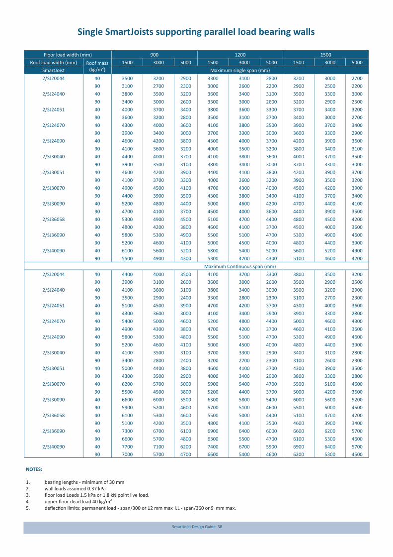
SmartJoist Design Guide 38
Single SmartJoists supporting parallel load bearing walls
NOTES: 1. bearing lengths - minimum of 30 mm 2. wall loads assumed 0.37 kPa 3. floor load Loads 1.5 kPa or 1.8 kN point live load. 4. upper floor dead load 40 kg/m2 5. deflection limits: permanent load - span/300 or 12 mm max LL - span/360 or 9 mm max.
Floor load width (mm) 900 1200 1500
Roof load width (mm) 1500 3000 5000 1500 3000 5000 1500 3000 5000 Roof mass (kg/m2) SmartJoist Maximum single span (mm)
2/SJ20044 40 3500 3200 2900 3300 3100 2800 3200 3000 2700
90 3100 2700 2300 3000 2600 2200 2900 2500 2200
2/SJ24040 40 3800 3500 3200 3600 3400 3100 3500 3300 3000
90 3400 3000 2600 3300 3000 2600 3200 2900 2500
2/SJ24051 40 4000 3700 3400 3800 3600 3300 3700 3400 3200
90 3600 3200 2800 3500 3100 2700 3400 3000 2700
2/SJ24070 40 4300 4000 3600 4100 3800 3500 3900 3700 3400
90 3900 3400 3000 3700 3300 3000 3600 3300 2900
2/SJ24090 40 4600 4200 3800 4300 4000 3700 4200 3900 3600
90 4100 3600 3200 4000 3500 3200 3800 3400 3100
2/SJ30040 40 4400 4000 3700 4100 3800 3600 4000 3700 3500
90 3900 3500 3100 3800 3400 3000 3700 3300 3000
2/SJ30051 40 4600 4200 3900 4400 4100 3800 4200 3900 3700
90 4100 3700 3300 4000 3600 3200 3900 3500 3200
2/SJ30070 40 4900 4500 4100 4700 4300 4000 4500 4200 3900
90 4400 3900 3500 4300 3800 3400 4100 3700 3400
2/SJ30090 40 5200 4800 4400 5000 4600 4200 4700 4400 4100
90 4700 4100 3700 4500 4000 3600 4400 3900 3500
2/SJ36058 40 5300 4900 4500 5100 4700 4400 4800 4500 4200
90 4800 4200 3800 4600 4100 3700 4500 4000 3600
2/SJ36090 40 5800 5300 4900 5500 5100 4700 5300 4900 4600
90 5200 4600 4100 5000 4500 4000 4800 4400 3900
2/SJ40090 40 6100 5600 5200 5800 5400 5000 5600 5200 4900
90 5500 4900 4300 5300 4700 4300 5100 4600 4200
Maximum Continuous span (mm)
2/SJ20044 40 4400 4000 3500 4100 3700 3300 3800 3500 3200
90 3900 3100 2600 3600 3000 2600 3500 2900 2500
2/SJ24040 40 4100 3600 3100 3800 3400 3000 3500 3200 2900
90 3500 2900 2400 3300 2800 2300 3100 2700 2300
2/SJ24051 40 5100 4500 3900 4700 4200 3700 4300 4000 3600
90 4300 3600 3000 4100 3400 2900 3900 3300 2800
2/SJ24070 40 5400 5000 4600 5200 4800 4400 5000 4600 4300
90 4900 4300 3800 4700 4200 3700 4600 4100 3600
2/SJ24090 40 5800 5300 4800 5500 5100 4700 5300 4900 4600
90 5200 4600 4100 5000 4500 4000 4800 4400 3900
2/SJ30040 40 4100 3500 3100 3700 3300 2900 3400 3100 2800
90 3400 2800 2400 3200 2700 2300 3100 2600 2300
2/SJ30051 40 5000 4400 3800 4600 4100 3700 4300 3900 3500
90 4300 3500 2900 4000 3400 2900 3800 3300 2800
2/SJ30070 40 6200 5700 5000 5900 5400 4700 5500 5100 4600
90 5500 4500 3800 5200 4400 3700 5000 4200 3600
2/SJ30090 40 6600 6000 5500 6300 5800 5400 6000 5600 5200
90 5900 5200 4600 5700 5100 4600 5500 5000 4500
2/SJ36058 40 6100 5300 4600 5500 5000 4400 5100 4700 4200
90 5100 4200 3500 4800 4100 3500 4600 3900 3400
2/SJ36090 40 7300 6700 6100 6900 6400 6000 6600 6200 5700
90 6600 5700 4800 6300 5500 4700 6100 5300 4600
2/SJ40090 40 7700 7100 6200 7400 6700 5900 6900 6400 5700
90 7000 5700 4700 6600 5400 4600 6200 5300 4500

SmartJoist Design Guide 39
SmartJoist as rafters
About roofs
Roof members are subject to dead and live loads as well as wind loads. These wind loads can act either down onto the roof, or can create an uplift effect. For roofs of light construction, the uplift loads generally control the maximum span, whereas it is usual for dead and live loads to be the controlling factors for heavier roofs (e.g. tiles). SmartJoists, by their large depth to width ratio, perform well in roof situations providing that their upper and lower flanges have adequate lateral support provided by battens and/or ceiling materials . Due to this fact, the spans in the table below only apply for roofs which meet the following criteria: - Enclosed building - Ceiling fastened to the underside of bottom flange or
adequate lateral supports to bottom flange at a minimum of 600 mm centres - Roofs are constructed as per details R1 to R9 of this manual - Batten spacing at a maximum of 1200 centres. Tie downs Wind loadings on light roofs can produce net uplift pressures. The same requirements and methods of tie down apply to SmartJoists as for solid timber roof members except that any tie down system must extend over the top flange. Guidance for tie down require-ments are provided in AS1684.
Roof slope
degrees
Depth factor 'df' Slope factor
‘sf' Joist depth (mm)
200 240 300 360 400
15.0 1.04 54 64 80 96 107
17.5 1.05 63 76 95 113 126
20.0 1.06 73 88 109 131 146
22.5 1.08 83 99 124 149 166
25.0 1.10 93 112 140 168 187
27.5 1.13 104 125 156 187 208
30.0 1.15 115 139 173 208 231
35.0 1.22 140 168 210 252 280
Sloped roof span and cut lengths
span (mm) = plan dimension x slope factor (sf) Cut length (mm) = horizontal length (h) x slope factor (sf) + depth factor (df) = h x sf + df
Ho riz on tal len gth 'h'
Ro of Pitch (in degrees)
Max overhang
600 mm
Rafter span
'df '
Plan dimensio n
Cut length
Joist Code
Single span @ 25o pitch Continuous 2 span @ 25o pitch Roof mass
(kg/m2)
Rafter/roof beam spacing (mm)
450 600 900 1200 450 600 900 1200
Recommended maximum rafter span - Plan dimension (mm)
SJ20044 40 5000 4600 4000 3650 N/A(1) N/A(1) N/A(1) 4550
90 3850 3500 3050 2750 N/A(1) 4900 4250 3800
SJ24040* 40 5600 5150 4500 4100 N/A(1) N/A(1) 4850 4300
90 4350 3950 3450 3100 N/A(1) 4750 4050 3550
SJ24051 40 6000 5550 4850 4450 N/A(1) N/A(1) N/A(1) 5200
90 4700 4250 3700 3350 N/A(1) N/A(1) 4950 4350
SJ24070 40 6600 6050 5350 4850 N/A(1) N/A(1) N/A(1) N/A(1)
90 5100 4650 4050 3650 N/A(1) N/A(1) N/A(1) N/A(1)
SJ24090 40 7000 6500 5750 5250 N/A(1) N/A(1) N/A(1) N/A(1)
90 5500 5050 4400 3950 N/A(1) N/A(1) N/A(1) N/A(1)
SJ30040* 40 6600 6100 5400 4850 N/A(1) N/A(1) N/A(1) N/A(1)
90 5200 4700 4100 3700 N/A(1) N/A(1) N/A(1) N/A(1)
SJ30051 40 7100 6550 5800 5300 N/A(1) N/A(1) N/A(1) N/A(1)
90 5600 5050 4450 4000 N/A(1) N/A(1) N/A(1) N/A(1)
SJ30070 40 7800 7200 6350 5800 N/A(1) N/A(1) N/A(1) N/A(1)
90 6100 5550 4850 4400 N/A(1) N/A(1) N/A(1) N/A(1)
SJ30090 40 8250 7700 6800 6250 N/A(1) N/A(1) N/A(1) N/A(1)
90 6550 6000 5200 4700 N/A(1) N/A(1) N/A(1) N/A(1)
SJ36058 40 8450 7950 7000 6400 N/A(1) N/A(1) N/A(1) N/A(1)
90 6750 6150 5400 4850 N/A(1) N/A(1) N/A(1) N/A(1)
SJ36090 40 9150 8650 7800 7150 N/A(1) N/A(1) N/A(1) N/A(1)
90 7550 6900 6000 5450 N/A(1) N/A(1) N/A(1) N/A(1)
SJ40090 40 9650 9150 8350 7750 N/A(1) N/A(1) N/A(1) N/A(1)
90 8150 7450 6500 5900 N/A(1) N/A(1) N/A(1) N/A(1)
NOTE: (1) Maximum Continuous spans exceed the maximum available length of the SmartJoist
*Product not currently available in NSW—check before ordering
Wind Classification N1 - N3 Max Deflections DL: Span/300 LL: Span/250 WL: Span/150. Max Slope = 25°.

SmartJoist Design Guide 40
Typical SmartJoist Roof details
Do n ot b evel c utjo ists b eyon d insideface o f w all .
Sm artJoi st b loc kin g or s im ilaris req uired at b earing to pro vid e lateral su pp ort.
B ird smou th cu t shallb ear fu lly an d no t o verhang th e inside face of th e p late.
2/65 x 3.15mmn ails (o ne each
side)
Web stif fen ers req uired eac hsi de of SmartJo ist.Bevel cu t stiffeners to m atc hro of slo pe. See Detail F1 2b .
2/ 65 x 3 .1 5m m n ail s(o ne eac h s ide)
Web stif fen ers req uired eac h
si de of SmartJo ist.Bevel cu t stiffeners to m atc hro of slo pe. See Detail F1 3.
Fi xin g p late to be bo lted to steel. Bo lt s ize as per En g sp eci ficatio n
Bi rds mo uth cu t s hal l bear fu lly and n ot o verhan g thein sid e face of the plate.
PFC, U C o r U BSteel B eam
50 m m w id th overh an g rafters. N otch arou nd Sm artJoi st top flan ge.
L
L
Jo ist shall b e d esi gnedus ing design p rop erties w hen "L " exceeds joi st sp aci ng.
14.73 m m
17.34 m m
Note: Tiedown details to be designed to AS 1684.2 for the respective wind loads with the SmartFrame software
B loc kin gb etween o utr iggersFace-Mo un t Hanger
(For roo f pi tch eq ual /les s th an 3 d eg ONLY)
Variable slo pe & skew jois t hanger
25x1.0mm G.I. strap w ith 7/3 5 x 3. 15 mmnails eac h end
25x1.0mm G.I. strap w ith 7/3 5 x 3. 15 mmnails eac h end
B evelled webst iff en er on b oth sides as p er detail F13
Bevel led web stiffener on b oth sides asper d etail F13
60 0 mm o verh an g & backs pan - 90 x 42 LVL15 o r similar at
60 0 m m cen tres90 0 mm o verh an g & backs pan- 130 x 42 LVL15 o r similar at 60 0 m m cen tres
Warning: Do not allow workers or loads on roof until ALL blocking, hanger, bracing and fastening is completed. See Safety warning
R4
R13
R7a
R3a R3b
R7b
R8
R9c
R9b R6b
R6a R5c
R9a
R5b R5a
R7c
R10b
R10a
R11
R1 R1a
R2
R3a R3b R4

SmartJoist Design Guide 41
Typical SmartJoist Roof details (cont’d)
Web stif fen ers req uiredb oth sides
B ird smou th cu t at bearin g.( Lim ited
to jo ists sp aced ata MAX of 6 00 m m)
M AX60 0 mm
90 x 45 ex tension rafter f or facia su pp ort
B ird smou th cu t at b ear in g. ( Bi rdsmo u thcu ts limited to jo istsp ac in g o f MAX 600 mm)M AX
60 0 mm
Web stif fen er requi red each sid e
M in 50 mm b eveled plate for
sl opes greater than 1 degree.
Trim & add bl ock ing (o ne eac h s ide) as des ired fo r fasci a su pp ort ( cu t to f it)
U se 2 rows o f 75 x 3.15mmnails at 100 m m c entres
Fi x rafters to b eveled plate (mi n 5 0 m m wi de fo r s lop es > 1 deg) with 1/75 x 3.15 m m nai l (o ne on eac h s ide)
M ini grip s o r s imi lar
as per m an ufactu rer sp eci ficatio n
Ti e-d ow n
strap as per m anu fac turer sp eci ficatio n
60 0 mmm ax.
Fasci a fi xed to en d of raf ters w ith nai l in to w eb-stif fen er, top flange & bo tto m flan ge
Web stiffener as per
detai l F12b
Bi rds mo uth cu t at beari ng.(B ird smo uth c uts limited tojo ist spacin g o f M ax 60 0 m m )
1200
50 m m w id th crip ple, cu t u nd er rafter ex ten sio n (Web
stiffener oth er sid e)
90 0 mm M AX
60 0 mm o verh an g 90 x4 2m m LVL 15 as extens ion raf ter and fix to Sm artJois t w ith 2 rows o f 65 x 3.15mm nails
at 2 00 mm c entres 9 00 m m o verhang 130x42mm LVL15 as extensio n rafter an d f ix to SmartJo ist with 2 ro ws o f 65 x 3.15mm n ai ls at 150 mm centres
Tw ist strap on bo th s idesNo . o f n ails & nail si ze as p er
m anu fac turer s pecific ati on
Panel b ac ker b loc k o n b oth sid es(With 18 nails)
30 d egrees max. angle
Bevel ed plateB ird smou th cu t no t p erm itted
25x1.0mm G.I. strap
w ith 7/3 5 x 3 .15 mmnails eac h end
Face mo un t or un iversal hanger(For roo f pi tch eq ual /les s than 3 deg O NLY)
25x1.0mm G.I. strap w ith 7/3 5 x 3 .15 mmnails eac h end
Variab le S lo pe & SkewJo ist Han ger
Bevel led web stiffener on b oth sides as per d etai l F1 2a
B evelled web st iff en er on bo thsides as p er detai l F12a
25x1.0mm G.I. strap w ith 7/3 5 x 3 .15 mmnails eac h end
Lo ng mu lti grip bracket o n b oth s idesWith 5 n ail s in to the web-s tiffner an dsu pp orting beam .Nail s ize : 3 .15 x 35m m galvanis ed20 0 an d 2 40 mm d eep rafter:-In stall 1 lo ng mu ltigrip bracket each sid e
30 0, 36 0 and 40 0 m m deep rafter: -Ins tal 2 l on g m ultigri p b rac ket eac h s ide
Bevel led web s tiffenero n b oth sid es as per d etai l F1 3
10 0 mm
Lo ng mu lti grip bracket o n b oth sides 5 n ails in to th e w eb-stif fen ers & s up portin g beam 2 nai ls i nto th e b otto mflange. Nail siz e : 3.1 5 x 35 mm galvanis ed
Sm artRim b loc kin g.(Toe nai l to to p p late at 15 0m m on center.)In stall as jo ists are set. Bevel ed plate o r
B ird smou th cu t at bearin g
Bevel led web s tiffenero n b oth sid es as per d etai l F1 3
R5a
R5b
R5c
R6a
R6b
R7a
R7b
R7c
R8
R9a
Rafter tie-down and blocking
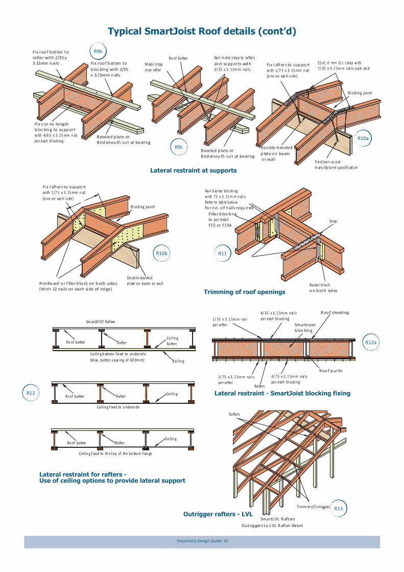
SmartJoist Design Guide 42
Typical SmartJoist Roof details (cont’d)
SmartJ oist b loc kin g
4/ 35 x 3 .1 5m m nai lsper each bl ock ing
R oo f p urlin4/ 75 x 3 .1 5m m nai lsper each bl ock ing
1/ 35 x 3 .1 5m m nai lper rafter
2/ 75 x 3 .1 5m m nai lsper rafter
Batten
R oo f sheeting
Dou ble-b eveled
p late o n beam o r wal l
R imBo ard o r f iller b lo ck on b oth sides. (With 12 nails on each side of rid ge)
Do ub le-beveledpl ate on beam or wall
Nail b ac ker blo cki ngw ith 75 x 3 .15 m m n ail s.Refer to tab le b elo w fo r n o . o f n ail s requ ired
Backer b loc ko n b oth sid es
Fi ller b loc kingAs per d etail F15 or F15A
Strap
Fix rafters to sup po rtw ith 1/7 5 x 3 .15 mm n ail(o ne on eac h s ide)
Ti e-d ow n as p erm anu fac turer s pecifi cati on
Bl ocking panel
Bl ock ing panel
Ceilin g b attens fix ed to un dersid e
(M ax . batten s pac ing of 60 0m m)
Ceilin g f ixed to th e top of the bo tto m f lan ge
Ceilin g f ixed to u ndersi de
Ro of batten
Ro of batten
Ro of batten
Rafter
Rafter
Rafter
Ceilin g
Ceilin g
Ceilin g
Ceilin gbatten
B eveled p late or B ird smou th cu t at bearing
Nail m etal s trap to rafters
an d su pp orts with 3/ 35 x 3 .1 5m m nai ls
M etal strap over rafter
Ro of batten
B eveled p late or B ird smou th cu t at bearing
Fix roo f b at ten torafter with 2/35 x 3.15mm n ai ls
Fix c ut -to -lengthb loc kin g to su pp ortw ith 4/6 5 x 3 .15 mm n ailper each bl ock ing
25 x1 .0 mm G.I. s trap w ith 7/ 35 x 3 .1 5m m nai ls each en d
Fix rafters to sup po rtw ith 1/7 5 x 3 .15 mm n ail
(o ne on eac h s ide)
Fix roo f b at ten to
b loc kin g with 2/35 x 3.15mm n ails
O utriggers to L VL R after Detail
Rafters
Trimm ers/O utriggers
Sm artJO IST Raf ters
SmartL VL R afters
R9b
R9c
R10a
R10b R11
R12
R12a
R13
Lateral restraint - SmartJoist blocking fixing
Lateral restraint at supports
Trimming of roof openings
Lateral restraint for rafters - Use of ceiling options to provide lateral support
Outrigger rafters - LVL
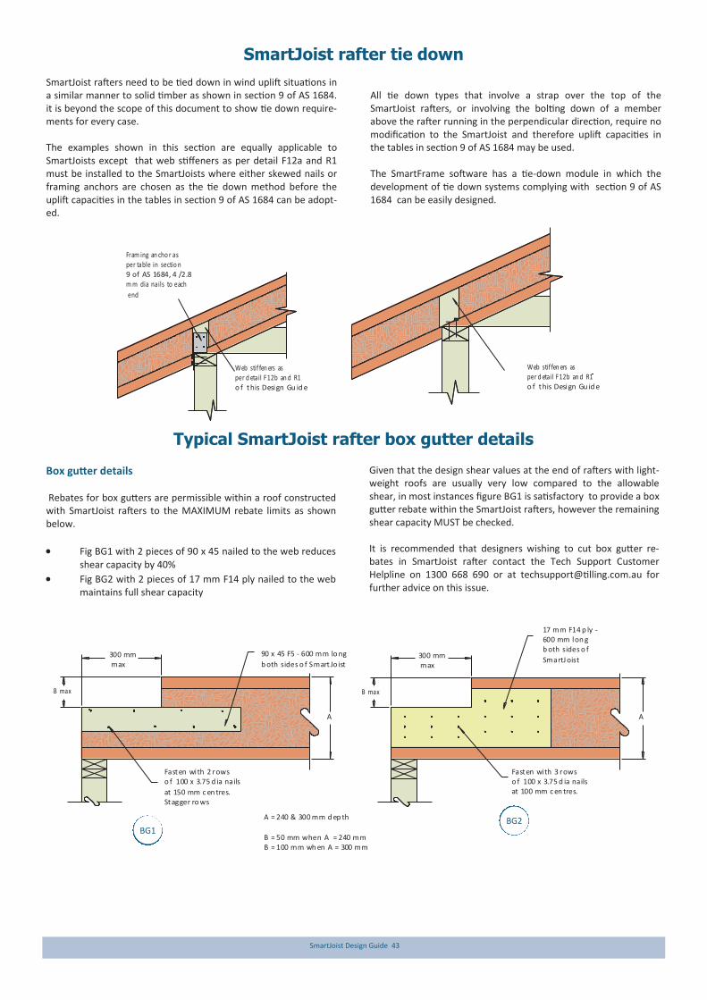
SmartJoist Design Guide 43
Typical SmartJoist rafter box gutter details
A = 240 & 300 mm d ep th
B = 50 mm when A = 240 mmB = 100 mm wh en A = 300 mm
90 x 45 F5 - 600 mm lo ng
b oth sides o f Smart Jo ist300 mm max
B max
Fasten with 2 rowso f 100 x 3.75 d ia nails
at 150 mm c en tres.Stagger ro ws
A
B max
A
300 mm max
Fasten with 3 rowso f 100 x 3.75 d ia nailsat 100 mm c en tres.
17 mm F14 p ly - 600 mm lon gb oth sides o f
SmartJ oist
Box gutter details Rebates for box gutters are permissible within a roof constructed with SmartJoist rafters to the MAXIMUM rebate limits as shown below.
Fig BG1 with 2 pieces of 90 x 45 nailed to the web reduces shear capacity by 40%
Fig BG2 with 2 pieces of 17 mm F14 ply nailed to the web maintains full shear capacity
Given that the design shear values at the end of rafters with light-weight roofs are usually very low compared to the allowable shear, in most instances figure BG1 is satisfactory to provide a box gutter rebate within the SmartJoist rafters, however the remaining shear capacity MUST be checked. It is recommended that designers wishing to cut box gutter re-bates in SmartJoist rafter contact the Tech Support Customer Helpline on 1300 668 690 or at [email protected] for further advice on this issue.
SmartJoist rafter tie down
SmartJoist rafters need to be tied down in wind uplift situations in a similar manner to solid timber as shown in section 9 of AS 1684. it is beyond the scope of this document to show tie down require-ments for every case. The examples shown in this section are equally applicable to SmartJoists except that web stiffeners as per detail F12a and R1 must be installed to the SmartJoists where either skewed nails or framing anchors are chosen as the tie down method before the uplift capacities in the tables in section 9 of AS 1684 can be adopt-ed.
All tie down types that involve a strap over the top of the SmartJoist rafters, or involving the bolting down of a member above the rafter running in the perpendicular direction, require no modification to the SmartJoist and therefore uplift capacities in the tables in section 9 of AS 1684 may be used. The SmartFrame software has a tie-down module in which the development of tie down systems complying with section 9 of AS 1684 can be easily designed.
Fram ing an cho r asper table in sectio n 9 of AS 1684, 4 /2.8m m dia nails to each
end
Web stif fen ers asper d etail F12b an d R1o f this Design Gu id e
Web stif fen ers asper d etail F12b an d R1o f this Design Gu id e
BG1 BG2

SmartJoist Design Guide 44
Building envelope watertightness - decks
Deck ledger attachments Many houses have decks attached to them. They are usually attached by first installing a deck ledger to the side of a house. The ledger carries the load for one end of the floor joists of the deck. The ledger and its attachment points penetrate the exteri-or cladding and must be flashed to protect the wall from rain water running down the cladding. This area of the wall experiences more rain exposure than most others because rain hitting the deck next to the wall splashes against the wall. "Free-standing" decks avoid this problem be-cause they do not penetrate the cladding envelope. As with window and door installations in walls, paying careful attention to flashing details is critical to avoid potential rot and mould of inner non treated wall frames and floor systems. Water from direct rainfall, splash from decks and runoff from incorrect-ly sloped deck surfaces can leak into the exterior wall where the deck attaches to the house.
Several conditions contribute to the water problem:
The ledger board is simply attached to the house with numerous lag screws or other hardware that penetrate the wall’s cladding and drainage plane, but no flashing has been installed to protect these areas
Water is often trapped behind the ledger board
Upward splashing of rain from the deck adds significant wetting to the cladding, and inadequate flashing results in wetting and rot in the wall’s framing and other internal elements.
Integrating the attachment of the ledger board with the drainage plane behind the wall’s cladding and adding proper flashing will maintain the integrity of the drainage plane and channel water away from the wall’s surface.
Untreated (optional H3) member Min 35 mm thick to support
bolting of deck ledger
Protectadeck or similar
Exterior cladding
Exterior cladding
Durability Class 1 or H3 treated timber deck ledger, depth at least 20 mm less than deck joists to prevent water entrapment
Flashing drip edge
Durability Class 1 or H3 treated
Z-flashing
Non treated SmartJoist
Breathable building wrap
Particleboard flooring
Bocoseal 16 or similar peel-and-stickwaterproof membrane
Min 10 mm gapto allow free
draining of deck
Breathable building wrap
316 Grade stainless steelor 300+ gsm hot dippedgalvanised joist hanger*
Stainless steel or hotdipped galvanised bolt*
* Bolt and joist hanger material based upon1. Timber treatment type2. Proximity to the sea3. Proximity to Industrial zones4. Proximity to chemicals/animals/swimming pools
Nail from bottom plate of upper wall frame at regular
intervals to allow memberto provide lateral bracing
to deck
Example flashing of deck ledger connection to un-treated house frame

SmartJoist Design Guide 45
10 00 m ax
Max
200/250* kg
per joist
Max 200/250* kg
per joist1000 min
10 00 m ax
16 00 m ax
16 00 m ax
10 00 m ax 1200
Joist direction
1200 10 00 m ax
16 00 m ax
16 00 m ax
1000 min
No materials stacked
in this area !Stair
opening
600
600
600
600
600
600
600
600
600
600
Safe loading of materials on a SmartJoist working platform
IMPORTANT!! Joists must be fully braced of have floor sheeting installed before applying any of the following loads.
* 200 kg per joist for joists less than 240 mm deep * 250 kg per joist for joists 240 mm and greater
Maximum distance to centre of load from face of support = 1600 mm. Maximum of 2 loads can be applied to 1 joist length, providing they are not more than 1600 mm from the face of the wall and a minimum of 1000 mm
between loads as shown.
Notes: 1. Deflection limit is taken as span/200 2. All timber must be kept dry when applying maximum temporary loading 3. Loads are to be spread equally over a minimum of 2 joists, using timber bearers at a minimum of 1200 mm in length or a standard 1200 x 1200 pallet 4. NO loads are to be stacked over any part of the lengths of the joists fixed to an opening header or trimmer joist such as a stair trimmer 5. If no plasterboard is in place under the joists, the bottom flange requires temporary bracing 6. Joists on hangers may require propping 7. If unsure about stacking concentrated loads on SmartJoist working platforms, please contact the SmartFrame Design Centre on 1300 668 690.

SmartJoist Design Guide 46
Fire safety The Building code of Australia became a performance-based code in 1996 (BCA96). The introduction of the BCA along with the changes to AS 1530.4 has seen Australia brought into line with international standards for fire resistance testing. The principle modification has been to express the test result in terms of the performance of the specimen Fire Resistance Level (FRL) rather than to assign a single rating as had been the established practice. The outcome of the test is expressed as the number of minutes for which the specimen fulfils the requirements of each of the three criteria, being: i. Structural adequacy ii. Integrity; and iii. Insulation, and expressed in that order The performance of a specimen is then given as the actual time for which the specimen satisfied these criteria, but rounded down to the nearest regulatory requirements. E.g. 60/60/60. Ceiling systems may also be required to provide “Resistance to the Incipient Spread of fire” for a given period of time. This re-quires the ceiling system to prevent the spread of fire within a roof/ceiling or floor/ceiling cavity by providing adequate thermal insulation to combustibles in this area, avoiding the danger of them igniting. To coincide with the changes, the FWPA produced a set of Wood Solutions manuals “Design and construction guide for BCA compliant fire-rated construction” which outlined the BCA requirements for all classes of buildings, design criteria and con-struction details which were designed to satisfy the BCA require-ments. Fire rated floors/ceilings The best information available at this time concludes that the fire resistance for ceiling and floor/ceilings is achieved by the lining material and that alternative joist sizes and material can be substi-tuted in the various certified systems, providing they are designed to support the full loads. The thickness of the fire grade ceiling lining for the relevant FRL is the same as required in the tested systems using solid timber joists. Additional testing have concluded that the following layers of fire rated plasterboard can achieve the FRL and incipient spread of fire as listed in the following table: The above ratings can be achieved using standard fire grade plas-
terboard from some sheet manufacturers. Other manufacturers may however require the use of special fire rated board or may still require the number of layers outlined in the Wood Solutions Design and construction guide for BCA compliant fire-rated con-struction.
For further details on the various certified systems, see the Wood Solution website www.woodsolutions.com.au or contact the engi-neers on the Tech Support Customer Helpline on 1300 668 690. Sound transmission The ability of walls and floors to reduce noise is measured over the most important part of the hearing range (from 125 to 4000 cycles per second), and the results reduced to a “weighted sound reduc-tion index” or Rw value. In 2004, the BCA introduced the addition of a Spectrum Adaption factor. This Ctr factor takes into account lower frequency level sounds, and has been chosen in large part, in recognition of the problem of the high bass frequency outputs of modern home theatre systems and amplified music systems. Therefore, both the Ctr and the Rw of the building element will now need to be considered. In addition to being rated for airborne sound transmission, floors are also rated by “Impact sound pressure level” or L’n,w plus the spectrum adaption factor Cl values that rate the capacity of floor assemblies to control impact noise such as footfalls. The lower the L’n,w +Cl of the floor, the better the performance of the floor in terms of impact sound insulation The BCA now requires a Rw+Ctr of 50 in floors between sole occu-pancy units and between dwellings and a plant room, lift shaft, stairway, public corridor, public lobby or similar. In 2004, the BCA introduced Deemed-to-satisfy provisions which require the L’n,w +Cl of a floor to be determined by testing in the laboratory. The impact sound insulation requirements for floors in the BCA is L’n,w +Cl not more than 62 for floor separating dwellings and floor separating dwellings from a plant room, lift shaft, stair-way, public corridor, public lobby or similar. The use of light-frame construction systems challenges designers to insulate against noise rather than simply relying on the massive-ness of heavy walls and floors. Excellent levels of noise control can be achieved with good acoustics in wood framed structures sur-faced with wood structural panels. Sound control can be achieved by applying floor and wall materials over isolated air spaces that absorb sound. The addition of resilient channels to support the ceiling system independently increases the Rw+Ctr and L’n,w +Cl ratings. The best current understanding indicates that the systems – walls, floors and ceiling” as detailed in the Wood Solutions manuals “Design and construction guide for BCA compliant fire-rated con-struction can be used to closely approximate the Rw+Ctr and L’n,w
+Cl rating of floor/ceiling systems with SmartJoist floor joists. Work is under way to further investigate the link between joist types and impact sound insulation. For further details on the various certified systems see www.woodsolutions.com.au or contact the engineers on the Tech Support Customer Helpline on 1300 668 690 or at [email protected]
Fire grade plasterboard FRL Incipient spread
of fire
1 x 13 mm 30/30/30 0
1 x 16 mm 60/60/60 30
2 x 13 mm 60/60/60 30
2 x 16 mm 90/90/90 60
3 x 16 mm 120/120/120 60
Fire safety and sound transmission

SmartJoist Design Guide 47
Q. Are the glues used in SmartFrame Engineered Wood Products safe? A. Yes, they are safe, Phenolic resins used in our Engineered
Wood Products are stable, polymerised materials. The
polymerisation reaction is non-reversible (i.e. once the polymer is
formed, it doesn’t break down). A wood dust warning label is
provided for all SmartFrame wood products to alert our
customers that wood dust can be generated by sawing, sanding,
or machining wood and wood products.
Q. What is the level of formaldehyde emission from our phenolic-bonded Engineered Wood Products? A. Independent third party testing has confirmed that formalde-hyde emissions from our phenolic-bonded products (i.e. OSB, LVL, and I-Joists) are below 0.5 mg/L under reasonably foreseeable conditions of use, which meets or exceeds the E0 Formaldehyde Emission Class In short, all available information indicates that formaldehyde
levels associated with phenolic resin-bonded wood products are
similar to those of the dimension lumber veneer or other forms of
wood used to make the products.
Q. How much formaldehyde is in our phenolic-bonded, Engi-neered Wood Products? A. The amount of formaldehyde in our Engineered Wood Prod-ucts is less than 0.1 percent of the dry weight.
Q. What is being done to reduce the exposure to formaldehyde? A. Formaldehyde is normally present at low levels, usually lower
than 0.03 ppm, in both outdoor and indoor air. Efforts have been
made by both government and industry to reduce exposure to
formaldehyde. A 1985 regulation by the US Department of
Housing and Urban Development (HUD), covering the use of
manufactured pressed wood products in housing was designed
to ensure that indoor levels were below 0.4 ppm. Product
standards established for plywood and particleboard led to
significant reductions in formaldehyde emissions from those
products. Furthermore, HUD acknowledged that phenolic resin
bonded wood products emitted such small quantities of
formaldehyde that these products were exempted from all the
testing and certification requirements of the standards. In
Germany, the German Hazardous Materials regulation, better
known as the “E1” Standard, sets a limit of 1.0 mg/L for
formaldehyde emissions from some wood-based composite
products. All available data indicates that our phenolic bonded
Engineered Wood Products meet the more stringent E0 level.
Q. What affects formaldehyde levels in a home? A. Formaldehyde levels in the indoor air depend mainly on what is releasing the formaldehyde, the temperature, the humidity, and the air exchange rate (i.e. the amount of outdoor air entering or leaving the indoor area) Levels of formaldehyde decrease with increasing air exchange rate, decreasing temperature, and de-creasing humidity.
Adhesive and formaldehyde emission facts sheet
The treatment of timber to extend its service life is covered by AS/NZS 1604. This code identifies the various biological hazards by a hazard class number, with hazard class numbers from H1 - H6. The higher the hazard class number, the greater the severity of the biological hazard. A complete table listing the 6 hazard classes is contained within AS/NZS 1604.1. All SmartJoists are supplied H2s treated per the table below, or alternatively may be after-market LOSP SmartGuard H2 treated by an experienced and approved timber preserver.
Water borne treatments are NOT suitable for SmartJoists. It is also NOT recommended that SmartJoists be specified for use outside above ground, even if H3 treated. This is predominately due to the geometric shape of the I-Joist which will not shed water effective-ly. Further information on SmartGuard treated I-Joists can be ob-tained on 1300 668 690 or at [email protected]
Hazard Class Exposure Specific service conditions Biological hazard Typical uses
H1* inside, above
ground Completely protected from the weather and well
ventilated, and protected from termites Lyctid borers
Interior beams, stair cases, string-ers
H2s inside, above
ground South of the Tropic of Capricorn ONLY Protected
from weather, Nil leaching Borers and termites
Interior joists, rafters and roof beams
H2 inside, above
ground Protected from weather, Nil leaching Borers and termites
Interior joists, rafters and roof beams
* All SmartJoists are manufactured from materials not susceptible to Lyctid attack
SmartGuard® preservative treatment

®
© Copyright Tilling Timber Pty Ltd ABN 92 004 621 121 SmartFrame is a registered Trademark of Tilling Timber Sept 2016
Proudly Australian Ownedwww.tilling.com.auilling
31-45 Orchard Street,Kilsyth, Victoria 3137
email: [email protected]
Phone +61 3 9725 0222Fax +61 3 9725 3045
New South Wales 109 Kurrajong Avenue,Mt Druitt, NSW 2770
email: [email protected]
Phone +61 2 9677 2600Fax +61 2 9677 2500
Queensland 20-24 Nealdon Drive,Meadowbrook, QLD, 4131
email: [email protected]
Phone +61 7 3440 5400Fax +61 7 3440 5444
Western Australia10 Cartwright Drive, Forrestdale, WA 6112
email: [email protected]
Phone +61 8 9399 1609Fax +61 8 9399 1065
South Australia5-9 Woomera Avenue,
email: [email protected]
Phone +61 8 8345 1966Fax +61 8 8345 1977
Edinburgh, SA 5111
Victoria