Embed Size (px)
Citation preview

ENGINEERING TOMORROW
Design GuideVLT® Brake Resistor MCE 101VLT® AutomationDrive FC 360
vlt-drives.danfoss.com


Contents
1 Introduction 4
1.1 Purpose of the Manual 4
1.2 Conformity 4
1.3 Safety Precautions 4
1.4 Disposal 4
2 Product Overview 5
2.1 Description of the Brake System 5
2.2 Horizontal or Vertical Load 5
2.2.1 How to Select 5
2.3 Aluminum-housed Brake Resistors 5
2.3.1 Aluminum-housed Flat-pack Brake Resistors 5
2.3.2 Aluminum-housed Compact Brake Resistor 6
2.4 Steel Grid Brake Resistors 6
3 Installation 7
3.1 Mechanical Installation 7
3.1.1 Aluminum-housed Compact Brake Resistors and Flat-pack Brake Resistors 7
3.1.2 Steel Grid Brake Resistors 10
3.1.3 Accessories 11
3.2 Electrical Installation 12
3.2.1 EMC Precautions 12
3.2.2 Cable Connection 13
3.2.3 Brake Cable 13
3.3 Protective Functions 13
3.3.1 Overtemperature Protection 13
3.3.2 Brake Resistor and Brake IGBT 15
4 System Integration 16
4.1 Brake Resistor Calculation 16
4.1.1 Brake Set-up 16
4.1.2 Calculation of Brake Resistor Resistance 16
4.1.3 Calculation of Braking Power 17
4.1.4 Calculation of the Brake Resistor Peak Power 17
4.1.5 Calculation of the Brake Resistor Average Power 17
4.1.6 Braking of Inertia 18
5 Parameters 19
6 Application Examples 21
6.1 Conveyor Belt 21
Contents Design Guide
MG06H102 Danfoss A/S © 09/2016 All rights reserved. 1

6.2 Centrifuge 23
6.3 Continuous Braking 23
7 Special Conditions 24
7.1 Alternative Braking Methods 24
7.1.1 DC Injection Braking 24
7.1.2 AC-braking 24
7.1.3 Mechanical Holding Brake 24
7.1.4 DC Braking 24
8 Selection Guide 25
8.1 Selection Flow Chart 25
8.2 Selection Tables for Recommended Brake Resistors 26
8.2.1 Abbreviations used in the Brake Resistor Tables 26
8.2.2 VLT® AutomationDrive FC 360 26
9 Specifications 28
9.1 Ambient Conditions 28
9.2 General Electrical Specifications 28
9.3 Electrical Data: MCE 101 Product Types 9xx 29
9.4 Mechanical Data: MCE 101 Product Types 9xx 39
9.5 Electrical Data: Product Types BWD and BWG 52
9.6 Mechanical Data: Product Types BWD and BWG 53
9.7 Mechanical Drawings 54
9.7.1 Figure 1 - 914CBT-HxxxDHT 54
9.7.2 Figure 2 - 914CBT-HxxxCHT 58
9.7.3 Figure 3 - 914CBT-HxxxBHT 61
9.7.4 Figure 4 - 914CBR-VxxxDT 64
9.7.5 Figure 5 - 914CBR-VxxxCT 67
9.7.6 Figure 6 - 914CBR-VxxxBT 69
9.7.7 Figure 7 - 914CCHxxxCT 72
9.7.8 Figure 8 - 917CM13 74
9.7.9 Figure 9 - 917CM15 76
9.7.10 Figure 10 - 917CM17 78
9.7.11 Figure 11 - 917CM25 80
9.7.12 Figure 12 - 917CM27 82
9.7.13 Figure 13 - 917CM37 84
9.7.14 Figure 14 - 917CMD27 86
9.7.15 Figure 15 - 917CMD37 88
9.7.16 Figure 16 - 929CBT-VxxxGHT 90
9.7.17 Figure 17 - 929CBT-VxxxBGHT 93
Contents VLT® Brake Resistor MCE 101
2 Danfoss A/S © 09/2016 All rights reserved. MG06H102

9.7.18 Figure 18 - 930CBT-VxxxGHT 96
9.7.19 Figure 19 - 930CBT- VxxxBGHT 99
9.7.20 Figure 20 - BWD250xxx 102
9.7.21 Figure 21 - BWD500xxx 103
9.7.22 Figure 22 - BWD600xxx 104
9.7.23 Figure 23 - BWG250xxx 105
9.7.24 Figure 24 - BWG500xxx 106
9.8 Mechanical Drawings: Accessories 107
9.8.1 Mounting Brackets: L Profile 107
9.8.2 Mounting Brackets: Footprint 109
Index 112
Contents Design Guide
MG06H102 Danfoss A/S © 09/2016 All rights reserved. 3

1 Introduction
1.1 Purpose of the Manual
The design guide provides the information required toselect and plan installation of the right brake resistor foran application:
• Selection of the correct brake resistor.
• Pre-installation considerations.
• Programming.
As an alternative to using a brake resistor, other brakingmethods can be applied depending on the braking profileof the application, see chapter 7 Special Conditions.
More technical literature is also available online atdrives.danfoss.com/knowledge-center/technical-documen-tation/.
1.2 Conformity
1)
Table 1.1 Approval
1) See Table 9.2 and Table 9.4 for UL conformity.
What is CE conformity and labelingThe purpose of CE labeling is to avoid technical tradeobstacles within EFTA and the EU. The EU has introducedthe CE label as a simple way of showing whether aproduct complies with the relevant EU directives. The CElabel says nothing about the specifications or quality ofthe product. Brake resistors are regulated by the followingEU directive:
The Low Voltage Directive (2014/35/EU)Brake resistors must be CE labeled in accordance with theLow Voltage Directive of April 20, 2016. The directiveapplies to all electrical equipment and appliances used inthe 50–1000 V AC and the 75–1500 V DC voltage ranges.Danfoss CE-labels in accordance with the directive andissues a declaration of conformity after request.
1.3 Safety Precautions
WARNINGSURFACE TEMPERATUREWhen in use, the brake resistor surface temperaturerises.
• DO NOT touch the brake resistor duringoperation.
WARNINGHAZARD DURING OPERATIONWork on a brake resistor in operation can result inserious injury.
• Never work on a brake resistor in operation.
• Ensure that only trained and qualified personnelcan work on a brake resistor.
NOTICENever attempt to repair a defective brake resistor.
1.4 Disposal
Equipment containing electrical componentsmay not be disposed of together withdomestic waste.It must be separately collected with electricaland electronic waste according to local andcurrently valid legislation.
Introduction VLT® Brake Resistor MCE 101
4 Danfoss A/S © 09/2016 All rights reserved. MG06H102
11

2 Product Overview
2.1 Description of the Brake System
When the speed reference of a frequency converter isreduced, the motor acts as a generator and the frequencyconverter brakes. When a motor acts as a generator, itsupplies energy to the frequency converter which iscollected in the DC link. The function of the brake resistoris to provide a load on the DC link during braking, therebyensuring that the braking power is absorbed by the brakeresistor.
If a brake resistor is not used, the DC-link voltage of thefrequency converter continues to increase, until discon-necting for protection. The advantage of using a brakeresistor is that it enables braking of a heavy load quickly,for example on a conveyor belt.
The brake resistors in this series are all externalcomponents. Therefore, the brake resistor does not forman integral part of the frequency converter.
The external brake resistor provides the followingadvantages:
• The resistor time cycle can be selected asrequired.
• The heat developed during braking can beconveyed beyond the panel cabinet to allow theenergy to be used.
• The electronic components do not overheat, evenwhen the brake resistor is overloaded.
2.2 Horizontal or Vertical Load
2.2.1 How to Select
The Danfoss brake resistor range consists of 2 groups:• Brake resistors for horizontal loads (conveyors,
trolleys, gantry cranes, and so on), seeIllustration 2.1;
• Brake resistors for vertical loads (cranes, hoists,elevators), see Illustration 2.2.
150/160%
175U
A06
7.10
Illustration 2.1 Horizontal Loads
100%
150/160%
175U
A06
8.10
Illustration 2.2 Vertical Loads
The brake resistor range is intended to cover the generalbraking requirements for horizontal and vertical brakeapplications.To select the best brake resistor for an application, refer to chapter 8.1 Selection Flow Chart. The flow chart links tofurther information, either selection tables or calculationsof inertia or duty cycle.
To cater for both the horizontal and vertical ranges, 3types of brake resistors are available:
• Aluminum-housed flat-pack brake resistors.
• Aluminum-housed compact brake resistors.
• Steel grid brake resistors.
2.3 Aluminum-housed Brake Resistors
2.3.1 Aluminum-housed Flat-pack BrakeResistors
The flat-pack brake resistor is an anodized aluminum-housed resistor suitable for wall mounting or on afootprint or an L-profile bracket. The L-profile bracket isused for rear mounting. The brake resistor is designed forhigh pulse loads of up to 40 times the nominal load and istherefore suitable for both vertical and horizontalapplications. The enclosure protection is IP54 or IP65.
130B
D24
5.12
1
Illustration 2.3 Flat-pack IP54
Product Overview Design Guide
MG06H102 Danfoss A/S © 09/2016 All rights reserved. 5
2 2

2.3.2 Aluminum-housed Compact BrakeResistor
The compact brake resistor is housed in aluminum profileswith pre-mounted brackets for wall mount. It is designedfor high pulse loads of up to 60 times the nominal loadand is therefore used for both horizontal and vertical loads.The enclosure protection class is either IP21, IP54, or IP65.The brake resistor IP classes IP21 and IP65 are equippedwith a connection box containing cable glands and cableconnection to the resistor and the temperature switch.IP54 versions have fixed unshielded cables.
130B
D64
6.10
Illustration 2.4 CBR-V-CT IP54
130B
D22
8.10
Illustration 2.5 CBR-V-DT IP21
130B
D21
7.10
Illustration 2.6 CBR-V-BT IP65
2.4 Steel Grid Brake Resistors
The steel grid brake resistor is steel grid housed andconsists of multiple elements. This brake resistor is suitablefor pulse loads between 10 and 20 times the nominal load,suitable for frequent braking applications such as cranes,hoists, and elevators. It is supplied in an IP20 enclosurewith cable glands and has a built-in temperature switch.
130B
D58
6.10
Illustration 2.7 Steel Grid House IP20
Product Overview VLT® Brake Resistor MCE 101
6 Danfoss A/S © 09/2016 All rights reserved. MG06H102
22

3 Installation
3.1 Mechanical Installation
The brake resistors are cooled by natural convection, andthe specified minimum clearances must be observed toensure efficient ventilation. The ventilation must beefficient enough to dispatch the regenerative power in thebrake resistor.
NOTICEWhen installing the brake resistor, ensure that allprecautions are in place to avoid the risk of overloading.Overloading can lead to a fire hazard due to the heatgenerated in the brake resistor.The brake resistor is hot during or after braking. Thebrake resistor must be located in a secure environmentto avoid fire risk.
• Mount the brake resistor free of any combustiblematerials at a well-ventilated location.
• The VLT® Brake Resistors MCE 101 brake resistorsproduct type 9xx contain a built-in temperatureswitch (for overtemperature protection purposes.See chapter 3.3 Protective Functions).
3.1.1 Aluminum-housed Compact BrakeResistors and Flat-pack Brake Resistors
The aluminum-housed compact and flat-pack brakeresistors are designed for vertical mounting for optimumcooling performance. However, horizontal mounting ispossible for both flat-pack and compact brake resistors.Derating with 20% is required when mounting thecompact brake resistors horizontally. No derating for flat-packs are required. The enclosure protection of the IP21types is reduced to IP20 when mounted horizontally.
NOTICEAll resistors are cooled by natural convection. To ensuresufficient airflow and cooling, follow minimum clearancein Illustration 3.1 to Illustration 3.8.
Vertical mounting, IP54For minimum clearances for vertical mounting for allaluminum-housed compact and flat-pack brake resistors,see Illustration 3.1 and Illustration 3.2.
130B
D90
0.10
200 mm
Illustration 3.1 Vertical Mounting, IP54Versions with Fixed Cables
Installation Design Guide
MG06H102 Danfoss A/S © 09/2016 All rights reserved. 7
3 3

130B
D90
1.10
200 mm
500
mm
200
mm
200 mm
Illustration 3.2 Vertical Mounting, IP54Versions with Fixed Cables
Horizontal mounting, IP54For minimum clearances for horizontal mounting for allaluminum-housed compact and flat-pack brake resistors,see Illustration 3.3 (top view).
200 mm200 mm
200
mm
200
mm
130B
D90
2.10
Illustration 3.3 Horizontal mounting, IP54Versions with Fixed Cables
For minimum clearances for horizontal mounting for allaluminum-housed compact and flat-pack brake resistors,IP54 versions (versions with fixed cables), see Illustration 3.4(side view).
130B
D90
3.10
500
mm
Illustration 3.4 Horizontal mounting, IP54Versions with Fixed Cables
Vertical mounting, IP21 and IP65For minimum clearances for vertical mounting for allaluminum-housed compact brake resistors, seeIllustration 3.5 and Illustration 3.6.
130B
D90
4.10
200 mm
Illustration 3.5 Vertical Mounting, IP21 and IP65Versions with Connection Box
Installation VLT® Brake Resistor MCE 101
8 Danfoss A/S © 09/2016 All rights reserved. MG06H102
33

200 mm 200 mm
500
mm
100
mm
130B
D90
5.10
Illustration 3.6 Vertical Mounting, IP21 and IP65Versions with Connection Box
Horizontal mounting, IP21 and IP65For minimum clearances for horizontal mounting for allaluminum-housed compact brake resistors, seeIllustration 3.7 (top view).
200
mm
100 mm 200
mm
200 mm
130B
D90
6.10
Illustration 3.7 Horizontal Mounting, IP21 and IP65Versions with Connection Box
Horizontal mounting, IP21 and IP65For minimum clearances for horizontal mounting for allaluminum housed compact brake resistors, seeIllustration 3.8 (side view).
130B
D90
7.10
500
mm
Illustration 3.8 Horizontal Mounting, IP21 and IP65Versions with Connection Box
Installation Design Guide
MG06H102 Danfoss A/S © 09/2016 All rights reserved. 9
3 3

Orientation, compact and flat-pack brake resistors
130B
D22
7.11
Illustration 3.9 Orientation of Compact and Flat-pack BrakeResistors
Derating with 20% is required when mounting thecompact brake resistors horizontally. The enclosureprotection of the IP21 types is reduced to IP20 whenmounted horizontally.
3.1.2 Steel Grid Brake Resistors
The steel grid brake resistors are designed for horizontalmounting only.
NOTICEAll resistors are cooled by natural convection. To ensuresufficient airflow and cooling, follow minimum clearancesin Illustration 3.10 and Table 3.3.
130B
D70
8.12
150
mm
150 mm
150 mm
150
mm
Illustration 3.10 Minimum Clearances of all Steel Grid BrakeResistors - Top View
500
mm
175Uxxxx
130B
D88
4.10
Illustration 3.11 Minimum Clearances of all Steel Grid BrakeResistors - Side View
Installation VLT® Brake Resistor MCE 101
10 Danfoss A/S © 09/2016 All rights reserved. MG06H102
33

175U
xxxx
130B
D70
9.11
Illustration 3.12 Orientation of Steel Grid Brake Resistors
3.1.3 Accessories
Footprint bracketsThe footprint bracket is an accessory used for mountingflat-pack brake resistors.
Use the footprint bracket to mount the brake resistor atthe rear of the frequency converter. Once mounted, thecombined brake resistor and frequency converter occupythe same space in the cabinet as the frequency converteralone.
1
2
3
130B
D59
5.10
1 Frequency converter
2 Footprint mounting bracket
3 Flat-pack brake resistor
Illustration 3.13 Flat-pack Brake Resistor Mounted at Rear ofFrequency Converter
Part number Compatible brake resistor Compatible frequencyconverter enclosuresize
175U00851x100 W flat-pack1x200 W flat-pack
A2
175U00872x100 W flat-pack2x200 W flat-pack
A2
175U00862x100 W flat-pack2x200 W flat-pack
A3
175U00881x100 W flat-pack1x200 W flat-pack
A3
Table 3.1 Selection Table
For mechanical dimensions for footprint brackets, seechapter 9.8.2 Mounting Brackets: Footprint.
Installation Design Guide
MG06H102 Danfoss A/S © 09/2016 All rights reserved. 11
3 3

L profile bracketsThe L profile bracket is an accessory used for mountingflat-pack brake resistors. The L profile brackets supportboth horizontally and vertically mounting on a fixedsurface optimizing the required footprint.
130B
D83
8.10
Illustration 3.14 L Profile Bracket
Part number Compatible brake resistor
175U0009 1x200 W flat-pack
175U00111)1x100 W flat-pack1x300 W flat-pack
Table 3.2
1) Order 2x175U0011 for 300 W flat-pack brake resistors.
For mechanical dimensions for L profile brackets, seechapter 9.8.1 Mounting Brackets: L Profile.
3.2 Electrical Installation
3.2.1 EMC Precautions
The following EMC precautions are recommended toachieve interference-free operation of fieldbus cable(s) anddigital and analog inputs and outputs.
Observe relevant national and local regulations, forexample regarding protective earth connection. Keep thefieldbus cable(s) away from motor cables and brake resistorcables to avoid coupling of high frequency noise from onecable to another. Normally, a distance of 200 mm (8inches) is sufficient, but keeping the greatest possibledistance between the cables is recommended, especiallywhere cables run in parallel over long distances. Whencrossing is unavoidable, the fieldbus cable(s) must crossmotor cables and brake resistor cables at an angle of 90°,see Illustration 3.15.
Fiel
dbus
cab
le
Min. 200 mm
90° crossing
Brake resistor
130B
D50
7.11
Illustration 3.15 Cable Routing
Installation VLT® Brake Resistor MCE 101
12 Danfoss A/S © 09/2016 All rights reserved. MG06H102
33

3.2.2 Cable Connection
NOTICETo comply with EMC emission specifications, shielded/armored cables are recommended.
NOTICECables general: All cabling must comply with nationaland local regulations on cable cross-sections andambient temperature.
See Table 3.3 for recommended temperature ratings for allcables and conductors connected to the brake resistor asground connection, thermal switch, and brake power.
IP class Recommended cables
IP20 ≥80 °C (176 °F)
IP21 ≥80 °C (176 °F)
IP54 ≥90 °C (194 °F)1)
IP65 ≥90 °C (194 °F)
Table 3.3 Cable Temperature Ratings
1) For ground connection.
How to connect more than 1 resistorStar parallel connection to ensure that load is sharedevenly between 2 or more resistors.
130B
B15
4.12
Illustration 3.16 Connection of Several Brake Resistors
Brake resistors with fixed cablesTo reduce the electrical noise from the wires between thebrake resistor and the frequency converter, twist the wires.For enhanced EMC performance, a metal shield can beused.
130B
F240
.10
(1) (2)
(1) Twisted pair
(2) Shielded cable
Illustration 3.17 Twisted Cables
3.2.3 Brake Cable
Maximum length: 20 m (66 ft) shielded cable.
Ensure the connection cable to the brake resistor isshielded. Connect the shielding to the conductive backplate of the frequency converter and to the brake resistormetal cabinet, using cable clamps.
3.3 Protective Functions
3.3.1 Overtemperature Protection
Danfoss VLT® Brake Resistors MCE 101 is equipped with agalvanic isolated temperature switch (PELV) that is closedunder normal operating conditions and open if the brakeresistor is overheated.
NOTICEUse the temperature switch as overtemperatureprotection feature to prevent damage of the brakeresistor caused by overtemperature. To prevent damageto the brake resistor, perform an immediate stop or aramp down.
There are several ways the temperature switch can beused:
The temperature switch as digital input to frequencyconverterExample 1
1. Connect terminal T1 of the brake resistor to thefrequency converter terminal 12 or 13.
2. Connect terminal T2 of the brake resistor to adigital input, for example terminal 18.
Automatic restart after enabling of the temperatureswitch:Select coast inverse for the selected digital input.
Installation Design Guide
MG06H102 Danfoss A/S © 09/2016 All rights reserved. 13
3 3

Prevent automatic restart:Select latched start for the selected digital input.
NOTICECoast does not terminate the brake function.
Example 1
81
82
99
91 92 93 95
96 97 98 99
12
18L1 L2 L3 PE
U V W PE
VLTMCE 101
Brake resistor
T1
T2
RB1
RB2
L1L2L3PE
F1
PE
R-
R+
PE
+24V
D-in
M3~
130B
D55
3.11
Illustration 3.18 Temperature Switch in Brake Resistor
NOTICEThe temperature switch as input to the frequencyconverter cannot be considered a primary safetyfunction.In case of a malfunction in the brake IGBT, the frequencyconverter and brake resistor are only protected bydisconnecting the mains supply to the frequencyconverter. The temperature switch must be connecteddisabling the mains supply to the frequency converter bya contactor preventing dangerous overtemperatures.
The temperature switch disabling the mains supply toVLT by a contactorExample 2
1. Connect the brake resistor built-in thermal switchas controlling an input contactor. In this example,the thermal switch within the brake resistor isconnected in series with the thermal switchwithin the motor.
2. Connect start and stop push buttons in serieswith the thermal switches.
3. Connect to a contactor in the mains supply infront of the frequency converter.
Thermal overheating in brake resistor or motor disables themains supply to the frequency converter.
Example 2
91 92 93 95
96 97 98 99
M 3~
12
27L1 L2 L3 PE
VLTMCE 101
Brake resistor
T1T2
RB1
RB299PE
81R -
82R+
PE
L1L2L3NPE
F1 S1 K1
F2
S2
K1
K1
U V W PE
130B
D55
4.11
Illustration 3.19 Temperature Switch in both Motor and BrakeResistor Disabling Mains Supply by an Input Contactor
Thermo relay disabling the brake resistorExample 3Calculate the brake current (Ithermo relay) setting of thetemperature switch as follows:
Ithermo relay= Pbrake resistor max
Rbr
Rbr is the current brake resistor value calculated in chapter 4.1.2 Calculation of Brake Resistor Resistance.
Look up the brake current setting of the thermo relay forDanfoss brake resistors in chapter 8 Selection Guide.
Installation VLT® Brake Resistor MCE 101
14 Danfoss A/S © 09/2016 All rights reserved. MG06H102
33

3.3.2 Brake Resistor and Brake IGBT
Brake resistor power monitorIn addition, the brake power monitor function makes itpossible to read out the momentary power and the meanpower for a selected time period. The brake can alsomonitor the power energizing and make sure that it doesnot exceed a limit selected in parameter 2-12 Brake PowerLimit (kW). In parameter 2-13 Brake Power Monitoring, selectthe function to carry out when the power transmitted tothe brake resistor exceeds the limit set inparameter 2-12 Brake Power Limit (kW).
NOTICEMonitoring the brake power does not fulfill a safetyfunction. The brake resistor circuit is not ground leakageprotected.
The brake is protected against short-circuiting of the brakeresistor, and the brake transistor is monitored to ensurethat short-circuiting of the transistor is detected. Use arelay or digital output to protect the brake resistor againstoverloading in the event of a fault in the frequencyconverter, see chapter 3.3.1 Overtemperature Protection.
Overvoltage control (OVC) can be selected as an alternativebrake function in parameter 2-17 Over-voltage Control. If theDC-link voltage increases, this function is active for allunits. The function ensures that a trip can be avoided. Thisis done by increasing the output frequency to limit thevoltage from the DC link. It is a useful function, forexample if the ramp-down time is too short since trippingof the frequency converter is avoided. In this situation, theramp-down time is extended.
Installation Design Guide
MG06H102 Danfoss A/S © 09/2016 All rights reserved. 15
3 3

4 System Integration
4.1 Brake Resistor Calculation
To ensure the optimal selection of brake resistor for agiven application, its inertia and braking profilecalculations are required.This chapter explains the calculations required to obtainvalues for optimal selection of brake resistor for a givenapplication.
4.1.1 Brake Set-up
The following sections use expressions and abbreviationsrelated to the brake set-up in Illustration 4.1.
Ppeak,mec.
175Z
A09
6.14
VLT
UDC
Itermo
PpeakPavg
RbrPb, max
Pmotor
ηINV = 0.98
ηmotor = 0.9
Illustration 4.1 Brake Set-up
4.1.2 Calculation of Brake ResistorResistance
To prevent the frequency converter from cutting out forprotection when the motor brakes, select resistor values onthe basis of the peak braking power and the DC-linkvoltage:
Rbr = Udc2
Ppeak ΩThe brake resistor performance depends on the DC-linkvoltage (Udc).
Udc is the voltage, where the brake is activated. The FC-series brake function is settled depending on the mainssupply.
DC-link voltage (Udc), VLT® AutomationDrive FC 360
Size [V]Brakeactive[V DC]
Overvoltagewarning[V DC]
Overvoltagealarm[V DC]
FC 360 3x380–480,0.37–22 kW (0.5–30hp)
700–7701) 800 800
FC 360 3x380–480,30–75 kW (40–100hp)
N/A2) 800 800
Table 4.1 DC-link Voltage (Udc), FC 360
1) Adjustable with parameter 2-14 Brake voltage reduce2) No built-in brake option
Use the brake resistance Rrec, to ensure that the frequencyconverter is able to brake at the highest braking torque(Mbr(%)) (for example 160%). The formula is written as:
Rrec Ω = Udc2 x 100
Pmotor x Mbr ( % ) x ηVLT x ηmotor
ηmotor is typically at 0.90ηVLT is typically at 0.98
When a higher brake resistor resistance is selected, 160%/150%/110% braking torque cannot be obtained, and thereis a risk that the frequency converter cuts out of DC-linkovervoltage for protection.
For braking at lower torque, for example 80% torque, it ispossible to install a brake resistor with lower power rating.Calculate size using the formula for calculating Rrec.
System Integration VLT® Brake Resistor MCE 101
16 Danfoss A/S © 09/2016 All rights reserved. MG06H102
44

4.1.3 Calculation of Braking Power
When calculating the braking power, ensure that the brakeresistor is scaled for the average power as well as the peakpower.
• The average power is determined by the processperiod time, that is the length of the brakingtime in relation to the process period time.
• The peak power is determined by the brakingtorque, which means that as braking progresses,the brake resistor must be able to dissipate theenergy input.
Illustration 4.2 shows the relation between the averagepower and the peak power.
P[W]
Ppeak
Pavg
Tp Tb
t [s]
175Z
A09
4.13
Tp Process period time in s
Tb Braking time in s
Illustration 4.2 Relation between Average Power and PeakPower
4.1.4 Calculation of the Brake Resistor PeakPower
Ppeak, mec is the peak power by which the motor brakes onthe motor shaft. Calculate Ppeak, mec as follows:
Ppeak, mec = Pmotor × MBR( % ) WPpeak is the braking power dissipated to the brake resistorwhen the motor brakes.
Ppeak is lower than Ppeak,mec since the power is reduced bythe efficiencies of the motor and the frequency converter.
Calculate Ppeak as follows:
Ppeak = Pmotor × MBR( % ) × ηmotor × ηVLT WWhen the brake resistor recommended by Danfoss isselected (Rrec) on the basis of the tables in chapter 8 Selection Guide, the brake resistor is certain toprovide a braking torque of 160%/150%/110% on themotor shaft.
4.1.5 Calculation of the Brake ResistorAverage Power
The average power is determined by the length of thebraking time in relation to the process period time.
When the kinetic energy (Eb) transferred to the resistor ineach braking sequence is known (see chapter 6.1 ConveyorBelt and chapter 6.2 Centrifuge), calculate the averagepower of the brake resistor as follows:
Pavg = Eb
Tp
WTp = period time in s, see Illustration 4.2.
When the kinetic energy transferred to the resistor in eachbraking sequence is not known, calculate the averagepower based on the process period time and the brakingtime.
Calculate the duty cycle for the braking sequence asfollows:
Duty cycle = Tb × 100Tp
%where
Tp = process period time in s
Tb = braking time in s
Danfoss offers brake resistors with a duty cycle ofmaximum 10% and 40%. If a 10% duty cycle is applied, thebrake resistors are able to absorb Ppeak for 10% of theperiod time. The remaining 90% of the period time is usedon deflecting excess heat.
Calculate the average power with 10% duty cycle asfollows:
Pavg = Ppeak × 10 % WCalculate the average power with 40% duty cycle asfollows:
Pavg = Ppeak × 40 % WThe calculations apply to intermittent braking using aperiod time of 30 s.
NOTICEExceeding the specified intermittent braking period timemay result in overheating the resistor.
System Integration Design Guide
MG06H102 Danfoss A/S © 09/2016 All rights reserved. 17
4 4

4.1.6 Braking of Inertia
When braking high inertia values on the motor shaft, basethe brake resistor values on the inertia, Δω, Δt, seeIllustration 4.3.
ω Start
ω Stop
∆t
∆ω/∆t
175Z
A86
3.11
Illustration 4.3 Braking of High Inertia
Δt is determined by the ramp-down time.
NOTICEThe ramp-down time goes from the rated motorfrequency to 0 Hz.
Ppeak can be calculated as:
Ppeak = ηmotor × ηVLT × ωstart × j × ΔωΔtPpeak = ηmotor × ηVLT × nstart × j × 2 × π
602 × ΔnΔt
j is the motor shaft inertia.
System Integration VLT® Brake Resistor MCE 101
18 Danfoss A/S © 09/2016 All rights reserved. MG06H102
44

5 Parameters
For descriptions of all available parameters, see VLT®
AutomationDrive FC 360 Programming Guide, which isavailable from drives.danfoss.com/knowledge-center/technical-documentation/.
2-10 Brake Function
Option: Function:
[0]*
Off No brake resistor is installed.
[1] Resistorbrake
A brake resistor is incorporated in the system fordissipating surplus brake energy as heat.Connecting a brake resistor allows a higher DC-link voltage during braking (generatingoperation). The brake resistor function is onlyactive in frequency converters with an integraldynamic brake.
[2] AC brake Improve braking without using a brake resistor.This parameter controls an overmagnetization ofthe motor when running with a generatoric load.This function can improve the OVC function.Increasing the electrical losses in the motorallows the OVC function to increase brakingtorque without exceeding the voltage limit.
NOTICEThe AC brake is not as efficient asdynamic braking with resistor.AC brake is for VVC+ mode in both openand closed loop.
2-11 Brake Resistor (ohm)
Range: Function:
Sizerelated*
[ 0 -65535Ohm]
Set the brake resistor value in Ω. Thisvalue is used for monitoring the power tothe brake resistor. Parameter 2-11 BrakeResistor (ohm) is only active in frequencyconverters with an integral dynamic brake.Use this parameter for values withoutdecimals.
2-12 Brake Power Limit (kW)
Range: Function:
Sizerelated*
[0.001 -2000kW]
Parameter 2-12 Brake Power Limit (kW) is theexpected average power dissipated in thebrake resistor over a period of 120 s. It isused as the monitoring limit forparameter 16-33 Brake Energy Average andspecifies when a warning/alarm is given.To calculate parameter 2-12 Brake PowerLimit (kW), the following formula can be
used.Pbr, avg W = Ubr2 V × tbr s
Rbr Ω × Tbr s
Pbr,avg is the average power dissipated inthe brake resistor. Rbr is the resistance ofthe brake resistor. tbr is the active breakingtime within the 120 s period Tbr.Ubr is the DC voltage where the brakeresistor is active. For T4 units, the DCvoltage is 778 V, which can be reduced by parameter 2-14 Brake voltage reduce.
NOTICEIf Rbr is not known or if Tbr is differentfrom 120 s, the practical approach isto run the brake application, read outparameter 16-33 Brake Energy Average,and then enter this value + 20% inparameter 2-12 Brake Power Limit(kW).
2-14 Brake voltage reduce
Range: Function:
0 V* [ 0 - 0 V] Setting this parameter may change the brakeresistor (parameter 2-11 Brake Resistor (ohm)).
2-16 AC Brake, Max current
Range: Function:
100 %* [0 -160 %]
Enter the maximum allowed current whenusing AC brake to avoid overheating ofmotor windings.
NOTICEParameter 2-16 AC Brake, Max currenthas no effect whenparameter 1-10 Motor Construction isset to [1] PM, non-salient SPM.
Parameters Design Guide
MG06H102 Danfoss A/S © 09/2016 All rights reserved. 19
5 5

2-17 Over-voltage Control
Option: Function:
Overvoltage control (OVC) reduces the risk ofthe frequency converter tripping due to anovervoltage on the DC link caused bygenerative power from the load.
[0] * Disabled No OVC required.
[1] Enabled(not atstop)
Activate OVC except when using a stop signalto stop the frequency converter.
[2] Enabled Activate OVC.
CAUTIONPERSONAL INJURY ANDEQUIPMENT DAMAGEEnabling OVC in hoisting applicationsmay lead to personal injuries andequipment damage.
• DO NOT enable OVC in hoistingapplications.
Parameters VLT® Brake Resistor MCE 101
20 Danfoss A/S © 09/2016 All rights reserved. MG06H102
55

6 Application Examples
6.1 Conveyor Belt
Illustration 6.1 shows the relation between the brakingpower and the acceleration/braking of a conveyor belt.Note:
• The motor power during braking is negative,since the torque on the motor shaft is negative.
• The motor power is time-dependent.
The braking power (the power to be dissipated to thebrake resistor) corresponds almost exactly to the negativemotor power plus losses in the motor and the frequencyconverter.
Kinetic energy (E) in conveyor belt + motor:
E = 0 . 5 × m × v2 + 0 . 5 × j × ω2 Wswhere
m = mass with linear movement [kg].
v = speed of mass with linear movement [m/s].
j = inertia of motor and gear box [kgm2].
ω = motor speed [rad/s].
ω = motor speed = n × 2π60 rad/s
This formula is also expressed as follows:
E = 0 . 50 × m × v2 + 0 . 0055 × j × n2 WsHowever, not all of the energy is dissipated in the brakeresistor. The friction of the conveyor belt and the powerloss of the motor also contribute to the braking function.So, the formula for energy dissipation (Eb) to the brakeresistor is as follows:
Eb = 0 . 5 × m v2 + 0 . 5 jω2 − 0 . 5 × M fω × ηM Ws where
Mf = Friction torque [Nm].
ŋM = Motor efficiency.
Insert:
ω = n × 2π60
The result is:
Eb = 0 . 5 × m v2 + 0 . 0055 × j × n2 − 0 . 052 × n × M f × ηM Ws
Application Examples Design Guide
MG06H102 Danfoss A/S © 09/2016 All rights reserved. 21
6 6

Paverage
Time [s]
Time [s]
Time [s]
Time [s]
Length [m]
175Z
A39
7.14
Acceleration Braking
Pbraking, avg.
P[W]
Motor power
P[W]
Brake power
M[Nm]
Torque
V[m/s]
Speed
VLT® M
V[m/s]
Speed
m v
Tp
m
ϖ[m/s]
Tp
Illustration 6.1 Conveyor Belt: Relation Between Braking Power and Acceleration/Deceleration
Application Examples VLT® Brake Resistor MCE 101
22 Danfoss A/S © 09/2016 All rights reserved. MG06H102
66

6.2 Centrifuge
Illustration 6.2 Centrifuge with Brake Resistor
Illustration 6.2 shows braking of a centrifuge, which is atypical application of brake resistors.The formula for energy dissipation (Eb) to the brake resistoris:
Eb = 0 . 0055 × jc × n22 + 0 . 0055 × jM × n12 × ηM Wswhere
m = weight of the centrifuge content [kg].
jC = centrifuge inertia [kgm2] = 0.5 x m (r12 + r22).
jM = gear motor inertia [kgm2].
ηM = gear motor efficiency.
n1 = maximum motor speed [RPM].
n2 = maximum centrifuge speed [RPM].
Rb = brake resistor.
6.3 Continuous Braking
To achieve continuous braking, select a brake resistor inwhich the constant braking power does not exceed theaverage power Pavg of the brake resistor.
NOTICEContact the Danfoss distributor for further information.
Application Examples Design Guide
MG06H102 Danfoss A/S © 09/2016 All rights reserved. 23
6 6

7 Special Conditions
7.1 Alternative Braking Methods
7.1.1 DC Injection Braking
If the 3-phase winding of the stator is fed with directcurrent, a stationary magnetic field Φ is set up in thestator bore causing a voltage to be induced in the bars ofthe cage rotor as long as the rotor is in motion. Since theelectrical resistance of the rotor cage is very low, evensmall induced voltages can create a high rotor current. Thiscurrent produces a strong braking effect on the bars andhence on the rotor. As the speed decreases, the frequencyof the induced voltage decreases and with it the inductiveimpedance. The ohmic resistance of the rotor graduallybecomes dominant and so increases the braking effect asthe speed decreases. The braking torque generateddecreases steeply just before standstill and finally ceaseswhen there is no further movement. Direct currentinjection braking is therefore not suitable for holding aload at rest.
7.1.2 AC-braking
When the motor acts as a brake, the DC-link voltageincreases because energy is fed back to the DC-link. Theprinciple in AC brake is to increase the magnetizationduring the braking and thereby increase the thermal lossesof the motor.
7.1.3 Mechanical Holding Brake
A mechanical holding brake mounted directly on themotor shaft normally performs static braking. In someapplications, the static holding torque is working as staticholding of the motor shaft (usually synchronouspermanent motors). A holding brake is either controlled bya PLC or directly by a digital output from the frequencyconverter (relay or solid state).
NOTICEWhen the holding brake is included in a safety chain:A frequency converter cannot provide a safe control of amechanical brake. A redundancy circuitry for the brakecontrol must be included in the total installation.
7.1.4 DC Braking
Resistor brake is useful from maximum speed down to acertain frequency. Below this frequency, DC braking is tobe applied as required. The most efficient way of doingthis is to use a combination of dynamic braking and DCbraking. See Illustration 7.1. The parameters are in chapter 5 Parameters.
175Z
A09
3.10
Illustration 7.1 Optimum Braking
How to calculate optimum DC-brake cut in frequency:
Slip s = n0 − nn
n0 × 100 %
Synchronous speed n0 = f × 60p [1/min]
f = frequency supplied to motor.p = number of pole pairs.nn = speed of the rotor.
DC-brake cut in frequency = 2 × s × f100 Hz
Special Conditions VLT® Brake Resistor MCE 101
24 Danfoss A/S © 09/2016 All rights reserved. MG06H102
77

8 Selection Guide
8.1 Selection Flow Chart
To select the correct size of brake resistor for an application, refer to the flow chart in Illustration 8.1.
1. Select an answer to each question from the top down.
2. Follow the answer to reach the next question, or to obtain guidance in calculating inertia or duty cycle.
3. The final box indicates the correct selection table, or whether to call hotline for additional guidance.
Select a 10%duty cycle brakeresistor from theselection tables
Select a 10%duty cycle brakeresistor from theselection tables
Select a 40%duty cycle brakeresistor from theselection tables
Please contactDanfoss1)
Please contactDanfoss1)
130B
B14
8.13
Low intertiaramp down>15 s
Low or highintertia?
Horizontal Vertical
Horizontal orvertical movement?
Determine brakingtime of theapplication
Braking time<brake resistor period
Braking time>brake resistor period
Calculate dutycycle
duty cycle <10% duty cycle >40%
duty cycle rangingfrom 10-40%
High inertiaramp down<15 s
or don’t know
Compare the brakingtime with the resistors
braking period
Illustration 8.1 Brake Resistor Selection Flow Chart
1) When contacting Danfoss, provide the following data:• Nominal power 100%
• Maximum power during brake cycle
• Braking time/duty cycle
• Supply voltage (maximum DC)
• Resistance (Ω)
• With or without temperature switch
• IP enclosure rating
• Type of reference drive
Selection Guide Design Guide
MG06H102 Danfoss A/S © 09/2016 All rights reserved. 25
8 8

8.2 Selection Tables for Recommended Brake Resistors
8.2.1 Abbreviations used in the Brake Resistor Tables
Mains Voltage class.
Pm Rated motor size for frequency converter.
Rmin Minimum allowed brake resistor - by frequency converter.
Rrec Recommended brake resistor resistance of Danfoss brake resistors.
Thermo relay Brake current setting of external thermo relay.
Danfoss part number Danfoss brake resistor order numbers.
Cable cross-sectionRecommended minimum value based upon PVC insulated copper cable. 30 °C (86 °F) ambient temperature withnormal heat dissipation.
Pbr,cont.Brake resistor average rated power. The temperature switch enables at approximately 90% of continuous ratedpower at brake resistors with IP54, IP21, and IP65 enclosure protection.
Rbr,nom The nominal (calculated) resistor value to ensure a brake power on motor shaft of 150/160/110% for 1 minute.
8.2.2 VLT® AutomationDrive FC 360
10% duty cycle, horizontal braking, T4FC 360 Horizontal braking 10% duty cycle
Frequency converter dataBrake resistor data Installation
Rrec
[Ω]Pbr,cont.
[kW (hp)]
Danfoss part number Cablecross-
section
[mm2
(AWG)]
Thermorelay
[A]Mainstype
Pm
[kW(hp)]
Rmin
[Ω]Rbr,nom
[Ω]
Wire IP54
Screwterminalterminal
IP21
Screwterminal
IP65
Boltconnection
IP20
T40.37(0.5)
890 1042 1200 0.1 (0.13) 175u3000 – – – 1.5 (16) 0.3
T40.55
(0.75)593 694 850 0.1 (0.13) 175u3001 – – – 1.5 (16) 0.4
T4 0.75 (1) 434 509 630 0.1 (0.13) 175u3002 – – – 1.5 (16) 0.4
T4 1.1 (1.5) 288 338 410 0.1 (0.13) 175u3004 – – – 1.5 (16) 0.5
T4 1.5 (2) 208 244 270 0.2 (0.27) 175u3007 – – – 1.5 (16) 0.8
T4 2.2 (3) 139 164 200 0.2 (0.27) 175u3008 – – – 1.5 (16) 0.9
T4 3 (4) 100 119 145 0.3 (0.4) 175u3300 – – – 1.5 (16) 1.3
T4 4 (5.5) 74.0 87.9 110 0.45 (0.6) 175u3335 175u3450 175u3449 – 1.5 (16) 1.9
T4 5.5 (7.5) 54.0 63.3 80 0.57 (0.76) 175u3336 175u3452 175u3451 – 1.5 (16) 2.5
T4 7.5 (10) 38.0 46.1 56 0.68 (0.91) 175u3337 175u3027 175u3028 – 1.5 (16) 3.3
T4 11 (15) 27.0 33.0 38 1.13 (1.5) 175u3338 175u3034 175u3035 – 1.5 (16) 5.2
T4 15 (20) 19.0 24.0 28 1.4 (1.9) 175u3339 175u3039 175u3040 – 1.5 (16) 6.7
T4 18.5 (25) 16.0 19.4 22 1.7 (2.28) 175u3340 175u3047 175u3048 – 1.5 (16) 8.3
T4 22 (30) 16.0 18.0 19 2.2 (3) 175u3357 175u3049 175u3050 – 1.5 (16) 10.1
T4 30 (40) 11.0 13.8 14 2.8 (3.8) 175u3341 175u3055 175u3056 – 2.5 (14) 13.3
T4 37 (50) 9.0 11.1 12 3.2 (4.3) 175u3359 175u3061 175u3062 – 2.5 (14) 15.3
T4 45 (60) 8.0 9.1 9.5 4.2 (5.6) – 175u3065 175u3066 – 4 (12) 20
T4 55 (75) 6.0 7.4 7.0 5.5 (7.4) – 175u3070 175u3071 – 6 (10) 26
T4 75 (100) 4.0 5.4 5.5 7 (9.4) – – – 175u3231 10 (8) 36
Table 8.1 T4, Horizontal Braking 10% Duty Cycle
Selection Guide VLT® Brake Resistor MCE 101
26 Danfoss A/S © 09/2016 All rights reserved. MG06H102
88

40% duty cycle, vertical braking, T4FC 360 Vertical braking 40% duty cycle
Frequency converter dataBrake resistor data Installation
Rrec
[Ω]Pbr,cont.
[kW (hp)]
Danfoss part number Cablecross-
section
[mm2
(AWG)]
Thermorelay
[A]Mainstype
Pm
[kW(hp)]
Rmin
[Ω]Rbr,nom
[Ω]
Wire IP54
Screwterminalterminal
IP21
Screwterminal
IP65
Boltconnection
IP20
T40.37(0.5)
890 1042 1200 0.2 (0.27) 175u3101 – – – 1.5 (16) 0.4
T40.55
(0.75)593 694 850 0.2 (0.27) 175u3308 – – – 1.5 (16) 0.5
T4 0.75 (1) 434 509 630 0.2 (0.27) 175u3309 – – – 1.5 (16) 0.7
T4 1.1 (1.5) 288 338 410 0.45 (0.6) 175u3310 175u3416 175u3415 – 1.5 (16) 1
T4 1.5 (2) 208 244 270 0.57 (0.76) 175u3311 175u3418 175u3417 – 1.5 (16) 1.4
T4 2.2 (3) 139 164 200 0.96 (1.29) 175u3312 175u3420 175u3419 – 1.5 (16) 2.1
T4 3 (4) 100 119 145 1.13 (1.5) 175u3313 175u3422 175u3421 – 1.5 (16) 2.7
T4 4 (5.5) 74.0 87.9 110 1.7 (2.3) 175u3314 175u3424 175u3423 – 1.5 (16) 3.7
T4 5.5 (7.5) 54.0 63.3 80 2.2 (3) 175u3315 175u3138 175u3139 – 1.5 (16) 5
T4 7.5 (10) 38.0 46.1 56 3.2 (4.3) 175u3316 175u3428 175u3427 – 1.5 (16) 7.1
T4 11 (15) 27.0 33.0 38 5 (6.7) – – – 175u3236 1.5 (16) 11.5
T4 15 (20) 19.0 24.0 28 6 (8) – – – 175u3237 2.5 (14) 14.7
T4 18.5 (25) 16.0 19.4 22 8 (10.7) – – – 175u3238 4 (12) 19
T4 22 (30) 16.0 18.0 19 10 (13.4) – – – 175u3203 4 (12) 23
T4 30 (40) 11.0 13.8 14 14 (19) – – – 175u3206 10 (8) 32
T4 37 (50) 9.0 11.1 12 17 (23) – – – 175u3210 10 (8) 38
T4 45 (60) 8.0 9.1 9.5 21 (28) – – – 175u3213 16 (6) 47
T4 55 (75) 6.0 7.4 7.0 26 (35) – – – 175u3216 25 (4) 61
T4 75 (100) 4.0 5.4 5.5 36 (48) – – – 175u3219 35 (2) 81
Table 8.2 T4, Vertical Braking 40% Duty Cycle
Selection Guide Design Guide
MG06H102 Danfoss A/S © 09/2016 All rights reserved. 27
8 8

9 Specifications
9.1 Ambient Conditions
EnvironmentAmbient temperature range -40 to 70 °C (-40 to 158 °F)Temperature range during storage/transport -40 to 70 °C (-40 to 158 °F)Maximum temperature at housing 300 °C (572 °F)Maximum relative humidity 5–85%, non-condensation during operationPower derating as a function of ambient temperature. (100% power rating and pulse-load):- Steel grid brake resistors, IP20 Continuous power 100% @ 40 °C (104 °F) to 70% @ 70 °C (158 °F), linear- Aluminum-housed compact brake resistors,IP21 Continuous power 100% @ 40 °C (104 °F) to 75% @ 70 °C (158 °F), linear- Aluminum-housed brake resistors - compactand flat-pack, IP54 Continuous power 100% @ 40 °C (104 °F) to 75% @ 70 °C (158 °F), linear- Aluminum compact brake resistors, IP65 Continuous power 100% @ 40 °C (104 °F) to 50% @ 70 °C (158 °F), linearPower derating at vertical mounted resistor (wall-mounted) when mounted horizontal (100% power rating and pulse-load):- Aluminum-housed flat-pack brake resistors, IP54 No derating- Aluminum-housed compact brake resistors, IP21, IP54, IP65 -20%Cooling requirements:The brake resistors are cooled by free natural convection. The power ratings of the resistors refers to cooling conditionswith free natural cooling. The requirements for minimum clearances must be observed during installation.Derating at high altitudes 100% @ 1000 m (3281 ft) above sea levelDerating at high altitudes 94% @ 1500 m (4921 ft) above sea levelDerating at high altitudes 82% @ 3000 m (9843 ft) above sea level
9.2 General Electrical Specifications
Electrical specificationsResistance tolerances ±10%Insulation >20 MΩ @ 1000 VDielectric strength 2500 V AC for 1 minuteOperating voltage:- Aluminum-housed compact brake resistors, IP54 UL: 600 V AC/600 V DC- Aluminum-housed compact brake resistors, IP54 IEC: 690 V AC/1100 V DC- Aluminum-housed flat-pack brake resistors, IP54 UL: 1000 V AC/1400 V DC- Aluminum-housed flat-pack brake resistors, IP54 IEC: 1000 V AC/1400 V DC- Aluminum-housed compact brake resistors, IP21, IP65 UL: 600 V AC/600 V DC- Aluminum-housed compact brake resistors, IP21, IP65 IEC: 690 V AC/1100 V DC- Steel grid brake resistors, IP20 IEC: 690 V AC/1100 V DCPower rating (continuous load 100%) with and without temperature switch- Without temperature switch 100% of continuous power rating @ 40 °C (104 °F)- With temperature switch, steel grid brake resistors, IP20 100% of continuous power rating @ 40 °C (104 °F)- With temperature switch, aluminum-housed brake resistors,IP21, IP54, IP65 Minimum 80% of continuous power rating @ 40 °C (104 °F)- With temperature switch, aluminum-housed brakeresistors, IP21, IP54, IP65
Temperature switch enables at ≥80% of the continuous power rating@ 40 °C (104 °F)
Electrical data temperature switch:- Steel grid brake resistors, IP20 10 A, 250 V AC, normally closed (NC). Enables at 260 °C (500 °F)- Aluminum-housed brake resistors, IP21, IP54, IP65 2 A, 250 V AC, normally closed (NC). Enables at 180 °C (356 °F)
Specifications VLT® Brake Resistor MCE 101
28 Danfoss A/S © 09/2016 All rights reserved. MG06H102
99

9.3 Electrical Data: MCE 101 Product Types 9xx
P/N Resi-stance
Continuouspower 100%
load
Pulseload
power10%duty
cycle1)
Pulseload
power40%duty
cycle1)
Temp.switch
2) 3)
Terminal maximum wirecross-section Wire cross-section4)
Temp. switch Power cables Temp. switch Power cables [Ω] [W] [kW (hp)] [kW (hp)] Type [mm2] [AWG] [mm2] [AWG] [mm2] [AWG] [mm2] [AWG]
175U3000 1200 100 1.65 (2.2) 0.405(0.54) 1 – – – – 0.5 20 1.5 16
175U3001 850 100 1.65 (2.2) 0.405(0.54) 1 – – – – 0.5 20 1.5 16
175U3002 630 100 1.65 (2.2) 0.405(0.54) 1 – – – – 0.5 20 1.5 16
175U3003 570 100 1.65 (2.2) 0.405(0.54) 1 – – – – 0.5 20 1.5 16
175U3004 410 100 1.65 (2.2) 0.405(0.54) 1 – – – – 0.5 20 1.5 16
175U3005 415 200 3.05 (4) 0.75 (1) 1 – – – – 0.5 20 1.5 16
175U3006 300 100 1.65 (2.2) 0.405(0.54) 1 – – – – 0.5 20 1.5 16
175U3007 270 200 3.05 (4) 0.75 (1) 1 – – – – 0.5 20 1.5 16175U3008 200 200 3.05 (4) 0.75 (1) 1 – – – – 0.5 20 1.5 16175U3009 200 360 4.2 (5.6) 1.05 (1.4) 1 4.0 12 16 6 – – – –175U3010 200 360 4.2 (5.6) 1.05 (1.4) 1 4.0 12 16 6 – – – –
175U3011 200 100 1.65 (2.2) 0.405(0.54) 1 – – – – 0.5 20 1.5 16
175U3012 145 450 5 (6.7) 1.25 (1.7) 1 4.0 12 16 6 – – – –175U3013 145 450 5 (6.7) 1.25 (1.7) 1 4.0 12 16 6 – – – –175U3014 145 280 2.8 (3.8) 0.7 (0.9) 1 4.0 12 16 6 – – – –175U3015 145 280 2.8 (3.8) 0.7 (0.9) 1 4.0 12 16 6 – – – –
175U3016 145 100 1.65 (2.2) 0.405(0.54) 1 – – – – 0.5 20 1.5 16
175U3017 110 360 4.2 (5.6) 1.05 (1.4) 1 4.0 12 16 6 – – – –175U3018 110 360 4.2 (5.6) 1.05 (1.4) 1 4.0 12 16 6 – – – –175U3019 105 570 6.6 (8.9) 1.65 (2.2) 1 4.0 12 16 6 – – – –175U3020 105 570 6.6 (8.9) 1.65 (2.2) 1 4.0 12 16 6 – – – –
175U3021 100 100 1.65 (2.2) 0.405(0.54) 1 – – – – 0.5 20 1.5 16
175U3022 80 450 5 (6.7) 1.25 (1.7) 1 4.0 12 16 6 – – – –175U3023 80 450 5 (6.7) 1.25 (1.7) 1 4.0 12 16 6 – – – –
175U3024 72 960 10.8(14.5) 2.6 (3.5) 1 4.0 12 16 6 – – – –
175U3025 72 960 13 (17.4) 3.3 (4.4) 1 4.0 12 16 6 – – – –175U3026 70 200 3.05 (4) 0.75 (1) 1 – – – – 0.5 20 1.5 16175U3027 56 680 9.4 (12.6) 2.2 (3) 1 4.0 12 16 6 – – – –175U3028 56 680 9.4 (12.6) 2.2 (3) 1 4.0 12 16 6 – – – –
175U3029 52 1290 17.8(23.9) 3.8 (5.1) 1 4.0 12 16 6 – – – –
175U3030 52 1290 17.8(23.9) 3.8 (5.1) 1 4.0 12 16 6 – – – –
175U3031 48 200 3.05 (4) 0.75 (1) 1 – – – – 0.5 20 1.5 16
175U3032 42 1700 21.1(28.3) 5.27 (7.1) 1 4.0 12 16 6 – – – –
175U3033 42 1700 21.1(28.3) 5.27 (7.1) 1 4.0 12 16 6 – – – –
175U3034 38 1130 15.6(20.9) 3.3 (4.4) 1 4.0 12 16 6 – – – –
175U3035 38 1130 14.5(19.4) 3.6 (4.8) 1 4.0 12 16 6 – – – –
175U3036 35 200 3.05 (4) 0.75 (1) 1 – – – – 0.5 20 1.5 16
175U3037 31 1700 21.1(28.3) 5.27 (7.1) 1 4.0 12 16 6 – – – –
175U3038 31 1700 21.1(28.3) 5.27 (7.1) 1 4.0 12 16 6 – – – –
Specifications Design Guide
MG06H102 Danfoss A/S © 09/2016 All rights reserved. 29
9 9

P/N Resi-stance
Continuouspower 100%
load
Pulseload
power10%duty
cycle1)
Pulseload
power40%duty
cycle1)
Temp.switch
2) 3)
Terminal maximum wirecross-section Wire cross-section4)
Temp. switch Power cables Temp. switch Power cables [Ω] [W] [kW (hp)] [kW (hp)] Type [mm2] [AWG] [mm2] [AWG] [mm2] [AWG] [mm2] [AWG]
175U3039 28 1400 17.5(23.5) 4.38 (5.9) 1 4.0 12 16 6 – – – –
175U3040 28 1400 17.5(23.5) 4.38 (5.9) 1 4.0 12 16 6 – – – –
175U3041 27 280 2.8 (3.8) 0.7 (0.9) 1 4.0 12 16 6 – – – –175U3042 27 280 2.8 (3.8) 0.7 (0.9) 1 4.0 12 16 6 – – – –
175U3043 27 2200 27.3(36.6) 6.8 (9.1) 1 4.0 12 16 6 – – – –
175U3044 27 2200 27.3(36.6) 6.8 (9.1) 1 4.0 12 16 6 – – – –
175U3047 22 1700 21.1(28.3) 5.27 (7.1) 1 4.0 12 16 6 – – – –
175U3048 22 1700 21.1(28.3) 5.27 (7.1) 1 4.0 12 16 6 – – – –
175U3049 19 2200 27.3(36.6) 6.8 (9.1) 1 4.0 12 16 6 – – – –
175U3050 19 2200 27.3(36.6) 6.8 (9.1) 1 4.0 12 16 6 – – – –
175U3051 15.5 3500 43.4(58.2)
10.8(14.5) 1 4.0 12 55 1/0 – – – –
175U3052 15.5 3500 43.4(58.2)
10.8(14.5) 1 4.0 12 55 1/0 – – – –
175U3053 18 450 6.2 (8.3) 1.45(1.94) 1 4.0 12 16 6 – – – –
175U3054 18 450 6.2 (8.3) 1.45(1.94) 1 4.0 12 16 6 – – – –
175U3055 14 2800 35 (46.9) 8.7 (11.7) 1 4.0 12 16 6 – – – –175U3056 14 2800 35 (46.9) 8.7 (11.7) 1 4.0 12 16 6 – – – –
175U3057 13.5 4200 52.5(70.4)
14.8(19.8) 1 4.0 12 55 1/0 – – – –
175U3058 13.5 4200 52.5(70.4)
14.8(19.8) 1 4.0 12 55 1/0 – – – –
175U3059 13 680 9.4 (12.6) 2.2 (3) 1 4.0 12 16 6 – – – –175U3060 13 680 9.4 (12.6) 2.2 (3) 1 4.0 12 16 6 – – – –
175U3061 12 3200 39.9(53.5) 9.9 (13.3) 1 4.0 12 16 6 – – – –
175U3062 12 3200 39.9(53.5) 9.9 (13.3) 1 4.0 12 16 6 – – – –
175U3063 11 5500 68.6 (92) 17 (22.8) 1 4.0 12 55 1/0 – – – –175U3064 11 5500 68.6 (92) 17 (22.8) 1 4.0 12 55 1/0 – – – –
175U3065 9.5 4200 52.5(70.4)
14.8(19.8) 1 4.0 12 55 1/0 – – – –
175U3066 9.5 4200 52.5(70.4)
14.8(19.8) 1 4.0 12 55 1/0 – – – –
175U3067 9.1 9000 121 (162) 29 (38.9) 2 2.5 14 2xM8 – – – –
175U3068 9.0 1130 14.5(19.4) 3.1 (4.2) 1 4.0 12 16 6 – – – –
175U3069 9.0 1130 14.5(19.4) 3.1 (4.2) 1 4.0 12 16 6 – – – –
175U3070 7.0 5500 68.6 (92) 17 (22.8) 1 4.0 12 55 1/0 – – – –175U3071 7.0 5500 68.6 (92) 17 (22.8) 1 4.0 12 55 1/0 – – – –175U3072 7.4 11000 148 (198) 36 (48.3) 2 2.5 14 2xM8 – – – –
175U3073 5.7 1400 17.5(23.5) 4.38 (5.9) 1 4.0 12 16 6 – – – –
175U3074 5.7 1400 17.5(23.5) 4.38 (5.9) 1 4.0 12 16 6 – – – –
175U3075 6.1 13000 174 (233) 42 (56.3) 2 2.5 14 2xM8 – – – –
175U3076 5.5 6300 87 (116.7) 20.5(27.5) 1 6.0 10 55 1/0 – – – –
Specifications VLT® Brake Resistor MCE 101
30 Danfoss A/S © 09/2016 All rights reserved. MG06H102
99

P/N Resi-stance
Continuouspower 100%
load
Pulseload
power10%duty
cycle1)
Pulseload
power40%duty
cycle1)
Temp.switch
2) 3)
Terminal maximum wirecross-section Wire cross-section4)
Temp. switch Power cables Temp. switch Power cables [Ω] [W] [kW (hp)] [kW (hp)] Type [mm2] [AWG] [mm2] [AWG] [mm2] [AWG] [mm2] [AWG]
175U3077 5.5 6300 87 (116.7) 20.5(27.5) 1 6.0 10 55 1/0 – – – –
175U3078 5.0 16000 215 (288) 52 (69.7) 2 2.5 14 2xM8 – – – –175U3079 4.7 9000 121 (162) 29 (38.9) 2 2.5 14 2xM8 – – – –
175U3080 3.5 2200 27.3(36.6) 6.8 (9.1) 1 4.0 12 16 6 – – – –
175U3081 3.5 2200 27.3(36.6) 6.8 (9.1) 1 4.0 12 16 6 – – – –
175U3082 4.0 20000 268 (359) 65 (87.2) 2 2.5 14 2xM8 – – – –175U3083 3.7 11000 148 (198) 36 (48.3) 2 2.5 14 2xM8 – – – –175U3084 3.3 13000 174 (233) 42 (56.3) 2 2.5 14 2xM8 – – – –175U3085 3.3 26000 349 (468) 85 (114) 2 2.5 14 2xM8 – – – –
175U3086 2.8 3200 39.9(53.5) 9.9 (13.3) 1 4.0 12 16 6 – – – –
175U3087 2.8 3200 39.9(53.5) 9.9 (13.3) 1 4.0 12 16 6 – – – –
175U3088 2.7 16000 215 (288) 52 (69.7) 2 2.5 14 2xM8 – – – –175U3089 2.5 32000 429 (575) 104 (139) 2 2.5 14 2xM8 – – – –
175U3090 2.3 36000 483 (648) 117(156.9) 2 2.5 14 2xM8 – – – –
175U3091 2.1 20000 268 (359) 65 (87.2) 2 2.5 14 2xM8 – – – –175U3092 2.0 42000 563 (755) 137 (184) 2 2.5 14 2xM8 – – – –175U3093 1.7 26000 349 (468) 85 (114) 2 2.5 14 2xM8 – – – –175U3094 1.6 52000 697 (935) 169 (227) 2 2.5 14 2xM8 – – – –
175U3095 1.4 60000 805(1080) 195 (261) 2 2.5 14 2xM8 – – – –
175U3096 300 200 3.05 (4) 0.75 (1) 1 – – – – 0.5 20 1.5 16175U3097 1.3 32000 429 (575) 104 (139) 2 2.5 14 2xM8 – – – –
175U3098 1.2 36000 483 (648) 117(156.9) 2 2.5 14 2xM8 – – – –
175U3099 1.1 42000 563 (755) 137 (184) 2 2.5 14 2xM8 – – – –175U3101 1200 200 3.05 (4) 0.75 (1) 1 – – – – 0.5 20 1.5 16175U3102 1200 360 4.2 (5.6) 1.05 (1.4) 1 4.0 12 16 6 – – – –175U3103 1200 360 4.2 (5.6) 1.05 (1.4) 1 4.0 12 16 6 – – – –175U3104 850 280 2.8 (3.8) 0.7 (0.9) 1 4.0 12 16 6 – – – –175U3105 850 280 2.8 (3.8) 0.7 (0.9) 1 4.0 12 16 6 – – – –
175U3106 145 2200 27.3(36.6) 6.8 (9.1) 1 4.0 12 16 6 – – – –
175U3107 145 2200 27.3(36.6) 6.8 (9.1) 1 4.0 12 16 6 – – – –
175U3108 630 360 4.2 (5.6) 1.05 (1.4) 1 4.0 12 16 6 – – – –175U3109 630 360 4.2 (5.6) 1.05 (1.4) 1 4.0 12 16 6 – – – –175U3110 570 570 6.6 (8.9) 1.65 (2.2) 1 4.0 12 16 6 – – – –175U3111 570 570 6.6 (8.9) 1.65 (2.2) 1 4.0 12 16 6 – – – –175U3112 415 790 9.5 (12.7) 2.37 (3.2) 1 4.0 12 16 6 – – – –175U3113 415 790 9.5 (12.7) 2.37 (3.2) 1 4.0 12 16 6 – – – –175U3114 410 570 6.6 (8.9) 1.65 (2.2) 1 4.0 12 16 6 – – – –175U3115 410 570 6.6 (8.9) 1.65 (2.2) 1 4.0 12 16 6 – – – –175U3116 270 790 9.5 (12.7) 2.37 (3.2) 1 4.0 12 16 6 – – – –175U3117 270 790 9.5 (12.7) 2.37 (3.2) 1 4.0 12 16 6 – – – –
175U3118 270 1130 14.5(19.4) 3.6 (4.8) 1 4.0 12 16 6 – – – –
175U3119 270 1130 14.5(19.4) 3.6 (4.8) 1 4.0 12 16 6 – – – –
175U3120 200 1130 14.5(19.4) 3.6 (4.8) 1 4.0 12 16 6 – – – –
175U3121 200 1130 14.5(19.4) 3.6 (4.8) 1 4.0 12 16 6 – – – –
Specifications Design Guide
MG06H102 Danfoss A/S © 09/2016 All rights reserved. 31
9 9

P/N Resi-stance
Continuouspower 100%
load
Pulseload
power10%duty
cycle1)
Pulseload
power40%duty
cycle1)
Temp.switch
2) 3)
Terminal maximum wirecross-section Wire cross-section4)
Temp. switch Power cables Temp. switch Power cables [Ω] [W] [kW (hp)] [kW (hp)] Type [mm2] [AWG] [mm2] [AWG] [mm2] [AWG] [mm2] [AWG]
175U3122 200 1700 21.1(28.3) 5.27 (7.1) 1 4.0 12 16 6 – – – –
175U3123 200 1700 21.1(28.3) 5.27 (7.1) 1 4.0 12 16 6 – – – –
175U3124 145 450 5 (6.7) 1.25 (1.7) 1 4.0 12 16 6 – – – –175U3125 145 450 5 (6.7) 1.25 (1.7) 1 4.0 12 16 6 – – – –
175U3126 145 1700 21.1(28.3) 5.7 (7.6) 1 4.0 12 16 6 – – – –
175U3127 145 1700 21.1(28.3) 5.27 (7.1) 1 4.0 12 16 6 – – – –
175U3130 110 2200 27.3(36.6) 6.8 (9.1) 1 4.0 12 16 6 – – – –
175U3131 110 2200 27.3(36.6) 6.8 (9.1) 1 4.0 12 16 6 – – – –
175U3132 105 3200 39.9(53.5) 9.9 (13.3) 1 4.0 12 16 6 – – – –
175U3133 105 3200 39.9(53.5) 9.9 (13.3) 1 4.0 12 16 6 – – – –
175U3134 105 4200 52.5(70.4)
14.8(19.8) 1 4.0 12 55 1/0 – – – –
175U3135 105 4200 52.5(70.4)
14.8(19.8) 1 4.0 12 55 1/0 – – – –
175U3136 100 570 6.6 (8.9) 1.65 (2.2) 1 4.0 12 16 6 – – – –175U3137 100 570 6.6 (8.9) 1.65 (2.2) 1 4.0 12 16 6 – – – –
175U3138 80 2200 27.3(36.6) 6.8 (9.1) 1 4.0 12 16 6 – – – –
175U3139 80 2200 27.3(36.6) 6.8 (9.1) 1 4.0 12 16 6 – – – –
175U3140 72 2800 35 (46.9) 8.7 (11.7) 1 4.0 12 16 6 – – – –175U3141 72 2800 35 (46.9) 8.7 (11.7) 1 4.0 12 16 6 – – – –
175U3142 72 4200 52.5(70.4)
14.8(19.8) 1 4.0 12 55 1/0 – – – –
175U3143 72 4200 52.5(70.4)
14.8(19.8) 1 4.0 12 55 1/0 – – – –
175U3144 70 790 9.5 (12.7) 2.37 (3.2) 1 4.0 12 16 6 – – – –175U3145 70 790 9.5 (12.7) 2.37 (3.2) 1 4.0 12 16 6 – – – –175U3146 56 2800 35 (46.9) 8.7 (11.7) 1 4.0 12 16 6 – – – –175U3147 56 2800 35 (46.9) 8.7 (11.7) 1 4.0 12 16 6 – – – –175U3148 52 5500 68.6 (92) 17 (22.8) 1 4.0 12 55 1/0 – – – –175U3149 52 5500 68.6 (92) 17 (22.8) 1 4.0 12 55 1/0 – – – –
175U3152 48 1400 17.5(23.5) 4.38 (5.9) 1 4.0 12 16 6 – – – –
175U3153 48 1400 17.5(23.5) 4.38 (5.9) 1 4.0 12 16 6 – – – –
175U3154 42 8200 102.2(137.1)
25.3(33.9) 1 6.0 10 55 1/0 – – – –
175U3155 42 8200 102.2(137.1)
25.3(33.9) 1 6.0 10 55 1/0 – – – –
175U3156 38 5500 68.6 (92) 17 (22.8) 1 4.0 12 55 1/0 – – – –175U3157 38 5500 68.6 (92) 17 (22.8) 1 4.0 12 55 1/0 – – – –
175U3160 35 1700 21.1(28.3) 5.27 (7.1) 1 4.0 12 16 6 – – – –
175U3161 35 1700 21.1(28.3) 5.27 (7.1) 1 4.0 12 16 6 – – – –
175U3162 31 8200 102.2(137.1)
25.3(33.9) 1 6.0 10 55 1/0 – – – –
175U3163 31 8200 102.2(137.1)
25.3(33.9) 1 6.0 10 55 1/0 – – – –
175U3166 28 6300 78.7(105.5)
19.5(26.1) 1 6.0 10 55 1/0 – – – –
Specifications VLT® Brake Resistor MCE 101
32 Danfoss A/S © 09/2016 All rights reserved. MG06H102
99

P/N Resi-stance
Continuouspower 100%
load
Pulseload
power10%duty
cycle1)
Pulseload
power40%duty
cycle1)
Temp.switch
2) 3)
Terminal maximum wirecross-section Wire cross-section4)
Temp. switch Power cables Temp. switch Power cables [Ω] [W] [kW (hp)] [kW (hp)] Type [mm2] [AWG] [mm2] [AWG] [mm2] [AWG] [mm2] [AWG]
175U3167 28 6300 78.7(105.5)
19.5(26.1) 1 6.0 10 55 1/0 – – – –
175U3168 27 2200 27.3(36.6) 6.8 (9.1) 1 4.0 12 16 6 – – – –
175U3169 27 2200 27.3(36.6) 6.8 (9.1) 1 4.0 12 16 6 – – – –
175U3170 22 8200 102.2(137.1)
25.3(33.9) 1 6.0 10 55 1/0 – – – –
175U3171 22 8200 102.2(137.1)
25.3(33.9) 1 6.0 10 55 1/0 – – – –
175U3172 18 3200 39.9(53.5) 9.9 (13.3) 1 4.0 12 16 6 – – – –
175U3173 18 3200 39.9(53.5) 9.9 (13.3) 1 4.0 12 16 6 – – – –
175U3174 13 3500 43.4(58.2)
10.8(14.5) 1 4.0 12 55 1/0 – – – –
175U3175 13 3500 43.4(58.2)
10.8(14.5) 1 4.0 12 55 1/0 – – – –
175U3176 9.0 5500 68.6 (92) 17 (22.8) 1 4.0 12 55 1/0 – – – –175U3177 9.0 5500 68.6 (92) 17 (22.8) 1 4.0 12 55 1/0 – – – –175U3178 5.7 5500 68.6 (92) 17 (22.8) 1 4.0 12 55 1/0 – – – –175U3179 5.7 5500 68.6 (92) 17 (22.8) 1 4.0 12 55 1/0 – – – –
175U3180 5.7 8200 102.2(137.1)
25.3(33.9) 1 6.0 10 55 1/0 – – – –
175U3181 5.7 8200 102.2(137.1)
25.3(33.9) 1 6.0 10 55 1/0 – – – –
175U3182 3.5 8200 102.2(137.1)
25.3(33.9) 1 6.0 10 55 1/0 – – – –
175U3183 3.5 8200 102.2(137.1)
25.3(33.9) 1 6.0 10 55 1/0 – – – –
175U3200 27.0 10000 134 (180) 33 (44.3) 2 2.5 14 2xM8 – – – –175U3201 27.0 14000 188 (252) 46 (61.7) 2 2.5 14 2xM8 – – – –175U3202 22.0 17000 228 (306) 55 (73.8) 2 2.5 14 2xM8 – – – –175U3203 19.0 10000 134 (180) 33 (44.3) 2 2.5 14 2xM8 – – – –175U3204 19 14000 188 (252) 46 (61.7) 2 2.5 14 2xM8 – – – –175U3205 15.5 21000 282 (378) 68 (91.2) 2 2.5 14 2xM8 – – – –175U3206 14.0 14000 188 (252) 46 (61.7) 2 2.5 14 2xM8 – – – –175U3207 14.0 17000 228 (306) 55 (73.8) 2 2.5 14 2xM8 – – – –175U3208 13.5 21000 282 (378) 68 (91.2) 2 2.5 14 2xM8 – – – –175U3209 13.5 26000 349 (468) 85 (114) 2 2.5 14 2xM8 – – – –175U3210 12.0 17000 228 (306) 55 (73.8) 2 2.5 14 2xM8 – – – –175U3211 11.0 26000 349 (468) 85 (114) 2 2.5 14 2xM8 – – – –
175U3212 11.0 36000 483 (648) 117(156.9) 2 2.5 14 2xM8 – – – –
175U3213 9.5 21000 282 (378) 68 (91.2) 2 2.5 14 2xM8 – – – –175U3214 9.1 42000 563 (755) 137 (184) 2 2.5 14 2xM8 – – – –175U3215 7.4 52000 697 (935) 169 (227) 2 2.5 14 2xM8 – – – –175U3216 7.0 26000 349 (468) 85 (114) 2 2.5 14 2xM8 – – – –
175U3217 7.0 36000 483 (648) 117(156.9) 2 2.5 14 2xM8 – – – –
175U3218 6.1 60000 805(1080) 195 (261) 2 2.5 14 2xM8 – – – –
175U3219 5.5 36000 483 (648) 117(156.9) 2 2.5 14 2xM8 – – – –
175U3220 5.0 78000 105 (141) 254 (341) 2 2.5 14 2xM8 – – – –175U3221 4.7 42000 563 (755) 137 (184) 2 2.5 14 2xM8 – – – –175U3222 4.0 90000 121 (162) 293 (393) 2 2.5 14 2xM8 – – – –175U3223 3.7 52000 69 (92.5) 169 (227) 2 2.5 14 2xM8 – – – –175U3224 3.5 14000 188 (252) 46 (61.7) 2 2.5 14 2xM8 – – – –
Specifications Design Guide
MG06H102 Danfoss A/S © 09/2016 All rights reserved. 33
9 9

P/N Resi-stance
Continuouspower 100%
load
Pulseload
power10%duty
cycle1)
Pulseload
power40%duty
cycle1)
Temp.switch
2) 3)
Terminal maximum wirecross-section Wire cross-section4)
Temp. switch Power cables Temp. switch Power cables [Ω] [W] [kW (hp)] [kW (hp)] Type [mm2] [AWG] [mm2] [AWG] [mm2] [AWG] [mm2] [AWG]
175U3225 3.3 60000 805(1080) 195 (261) 2 2.5 14 2xM8 – – – –
175U3227 2.8 17000 228 (306) 55 (73.8) 2 2.5 14 2xM8 – – – –175U3228 2.7 78000 105 (141) 254 (341) 2 2.5 14 2xM8 – – – –175U3230 2.1 90000 121 (162) 293 (393) 2 2.5 14 2xM8 – – – –175U3231 5.5 7000 94 (126) 23 (30.8) 2 2.5 14 2xM8 – – – –175U3232 11 7000 94 (126) 23 (30.8) 2 2.5 14 2xM8 – – – –175U3233 5.7 6000 80 (107) 20 (26.8) 2 2.5 14 2xM8 – – – –175U3234 5.7 8000 107 (143) 26 (34.9) 2 2.5 14 2xM8 – – – –175U3235 3.5 9000 121 (162) 29 (38.9) 2 2.5 14 2xM8 – – – –175U3236 38 5000 67 (90) 16 (21.5) 2 2.5 14 2xM8 – – – –175U3237 28 6000 80 (107) 20 (26.8) 2 2.5 14 2xM8 – – – –175U3238 22 8000 107 (143) 26 (34.9) 2 2.5 14 2xM8 – – – –175U3239 38 6000 80 (107) 20 (26.8) 2 2.5 14 2xM8 – – – –175U3240 31 8000 107 (143) 26 (34.9) 2 2.5 14 2xM8 – – – –175U3241 7.0 30000 402 (539) 98 (131) 2 2.5 14 2xM8 – – – –175U3242 52 6000 80 (107) 20 (26.8) 2 2.5 14 2xM8 – – – –175U3243 42 8000 107 (143) 26 (34.9) 2 2.5 14 2xM8 – – – –175U3244 31 10000 134 (180) 33 (44.2) 2 2.5 14 2xM8 – – – –175U3245 7 7000 94 (126) 23 (30.8) 2 2.5 14 2xM8 – – – –175U3300 145 300 5 (6.7) 1 (1.34) 1 – – – – 0.5 20 1.5 16175U3301 100 450 5 (6.7) 1.25 (1.7) 1 – – – – 0.5 20 1.5 16175U3302 70 570 6.6 (8.9) 1.65 (2.2) 1 – – – – 0.5 20 1.5 16
175U3303 48 960 11.5(15.4) 2.88 (3.9) 1 – – – – 0.5 20 1.5 16
175U3304 35 1130 14.5(19.4) 3.6 (4.8) 1 – – – – 0.5 20 1.5 16
175U3305 27 1400 17.5(23.5) 4.38 (5.9) 1 – – – – 0.5 20 6.0 10
175U3306 18 2200 27.3(36.6) 6.8 (9.1) 1 – – – – 0.5 20 6.0 10
175U3307 13 3200 39.9(53.5) 9.9 (13.3) 1 – – – – 0.5 20 6.0 10
175U3308 850 200 3.05 (4) 0.75 (1) 1 – – – – 0.5 20 1.5 16175U3309 630 300 5 (6.7) 1 (1.34) 1 – – – – 0.5 20 1.5 16175U3310 410 450 5 (6.7) 1.25 (1.7) 1 – – – – 0.5 20 1.5 16175U3311 270 570 6.6 (8.9) 1.65 (2.2) 1 – – – – 0.5 20 1.5 16
175U3312 200 960 10.8(14.5) 2.6 (3.5) 1 – – – – 0.5 20 1.5 16
175U3313 145 1130 14.5(19.4) 3.6 (4.8) 1 – – – – 0.5 20 1.5 16
175U3314 110 1700 21.1(28.3) 5.27 (7.1) 1 – – – – 0.5 20 6.0 10
175U3315 80 2200 27.3(36.6) 6.8 (9.1) 1 – – – – 0.5 20 6.0 10
175U3316 56 3200 39.9(53.5) 9.9 (13.3) 1 – – – – 0.5 20 6.0 10
175U3317 850 280 2.8 (3.8) 0.7 (0.9) 1 – – – – 0.5 20 1.5 16175U3318 570 450 5 (6.7) 1.25 (1.7) 1 – – – – 0.5 20 1.5 16175U3319 415 570 6.6 (8.9) 1.65 (2.2) 1 – – – – 0.5 20 1.5 16
175U3320 270 960 10.8(14.5) 2.6 (3.5) 1 – – – – 0.5 20 1.5 16
175U3321 200 1130 14.5(19.4) 3.6 (4.8) 1 – – – – 0.5 20 1.5 16
175U3322 145 1700 21.1(28.3) 5.27 (7.1) 1 – – – – 0.5 20 6.0 14
175U3323 100 2200 27.3(36.6) 6.8 (9.1) 1 – – – – 0.5 20 6.0 10
175U3324 72 3200 39.9(53.5) 9.9 (13.3) 1 – – – – 0.5 20 6.0 10
Specifications VLT® Brake Resistor MCE 101
34 Danfoss A/S © 09/2016 All rights reserved. MG06H102
99

P/N Resi-stance
Continuouspower 100%
load
Pulseload
power10%duty
cycle1)
Pulseload
power40%duty
cycle1)
Temp.switch
2) 3)
Terminal maximum wirecross-section Wire cross-section4)
Temp. switch Power cables Temp. switch Power cables [Ω] [W] [kW (hp)] [kW (hp)] Type [mm2] [AWG] [mm2] [AWG] [mm2] [AWG] [mm2] [AWG]
175U3325 35 300 5 (6.7) 1 (1.34) 1 – – – – 0.5 20 1.5 16175U3326 27 360 4.2 (5.6) 1.05 (1.4) 1 – – – – 0.5 20 1.5 16175U3327 18 570 6.6 (8.9) 1.65 (2.2) 1 – – – – 0.5 20 1.5 16175U3328 13 680 9.4 (12.6) 2.2 (3) 1 – – – – 0.5 20 1.5 16
175U3329 9.0 1130 14.5(19.4) 3.6 (4.8) 1 – – – – 0.5 20 1.5 16
175U3330 5.7 1400 17.5(23.5) 4.38 (5.9) 1 – – – – 0.5 20 6.0 10
175U3331 5.7 1700 21.1(28.3) 5.27 (7.1) 1 – – – – 0.5 20 6.0 10
175U3332 3.5 2200 27.3(36.6) 6.8 (9.1) 1 – – – – 0.5 20 6.0 10
175U3333 3.5 2800 35 (46.9) 8.7 (11.7) 1 – – – – 0.5 20 6.0 10
175U3334 2.8 3200 39.9(53.5) 9.9 (13.3) 1 – – – – 0.5 20 6.0 10
175U3335 110 450 6.6 (8.9) 1.65 (2.2) 1 – – – – 0.5 20 1.5 16175U3336 80 570 5 (6.7) 1.25 (1.7) 1 – – – – 0.5 20 1.5 16175U3337 56 680 9.4 (12.6) 2.2 (3) 1 – – – – 0.5 20 1.5 16
175U3338 38 1130 14.5(19.4) 3.6 (4.8) 1 – – – – 0.5 20 1.5 16
175U3339 28 1400 17.5(23.5) 4.38 (5.9) 1 – – – – 0.5 20 6.0 10
175U3340 22 1700 21.1(28.3) 5.27 (7.1) 1 – – – – 0.5 20 6.0 10
175U3341 14 2800 35 (46.9) 8.7 (11.7) 1 – – – – 0.5 20 6.0 10175U3342 200 300 5 (6.7) 1 (1.34) 1 – – – – 0.5 20 1.5 16175U3343 145 450 5 (6.7) 1.25 (1.7) 1 – – – – 0.5 20 1.5 16175U3344 100 570 6.6 (8.9) 1.65 (2.2) 1 – – – – 0.5 20 1.5 16175U3345 72 680 9.4 (12.6) 2.2 (3) 1 – – – – 0.5 20 1.5 16
175U3346 52 1130 14.5(19.4) 3.6 (4.8) 1 – – – – 0.5 20 1.5 16
175U3347 38 1400 17.5(23.5) 4.38 (5.9) 1 – – – – 0.5 20 6.0 10
175U3348 31 1700 21.1(28.3) 5.27 (7.1) 1 – – – – 0.5 20 6.0 10
175U3349 27 2200 27.3(36.6) 6 (8) 1 – – – – 0.5 20 6.0 10
175U3350 19 2800 35 (46.9) 8.7 (11.7) 1 – – – – 0.5 20 6.0 10
175U3351 72 1130 14.5(19.4) 3.6 (4.8) 1 – – – – 0.5 20 1.5 16
175U3352 52 1400 17.5(23.5) 4.38 (5.9) 1 – – – – 0.5 20 6.0 10
175U3353 42 1700 21.1(28.3) 5.27 (7.1) 1 – – – – 0.5 20 6.0 10
175U3354 31 2200 27.3(36.6) 6.8 (9.1) 1 – – – – 0.5 20 6.0 10
175U3355 27 2800 35 (46.9) 8.7 (11.7) 1 – – – – 0.5 20 6.0 10
175U3356 22 3200 39.9(53.5) 9.9 (13.3) 1 – – – – 0.5 20 6.0 10
175U3357 19 2200 27.3(36.6) 6.8 (9.1) 1 – – – – 0.5 20 6.0 10
175U3358 14 3200 39.9(53.5) 9.9 (13.3) 1 – – – – 0.5 20 6.0 10
175U3359 12 3200 39.9(53.5) 9.9 (13.3) 1 – – – – 0.5 20 6.0 10
175U3360 105 790 9.5 (12.7) 2.37 (3.2) 1 – – – – 0.5 20 1.5 16175U3361 270 300 5 (6.7) 1 (1.34) 1 – – – – 0.5 20 1.5 16175U3401 100 450 5 (6.7) 1.2 (1.6) 1 4.0 12 16 6 – – – –175U3402 100 450 5 (6.7) 1.25 (1.7) 1 4.0 12 16 6 – – – –175U3403 70 570 6.6 (8.9) 1.65 (2.2) 1 4.0 12 16 6 – – – –
Specifications Design Guide
MG06H102 Danfoss A/S © 09/2016 All rights reserved. 35
9 9

P/N Resi-stance
Continuouspower 100%
load
Pulseload
power10%duty
cycle1)
Pulseload
power40%duty
cycle1)
Temp.switch
2) 3)
Terminal maximum wirecross-section Wire cross-section4)
Temp. switch Power cables Temp. switch Power cables [Ω] [W] [kW (hp)] [kW (hp)] Type [mm2] [AWG] [mm2] [AWG] [mm2] [AWG] [mm2] [AWG]
175U3404 70 570 6.6 (8.9) 1.65 (2.2) 1 4.0 12 16 6 – – – –
175U3405 48 960 11.5(15.4) 2.88 (3.9) 1 4.0 12 16 6 – – – –
175U3406 48 960 11.5(15.4) 2.88 (3.9) 1 4.0 12 16 6 – – – –
175U3407 35 1130 14.5(19.4) 3.6 (4.8) 1 4.0 12 16 6 – – – –
175U3408 35 1130 14.5(19.4) 3.6 (4.8) 1 4.0 12 16 6 – – – –
175U3409 27 1400 17.5(23.5) 4.38 (5.9) 1 4.0 12 16 6 – – – –
175U3410 27 1400 17.5(23.5) 4.38 (5.9) 1 4.0 12 16 6 – – – –
175U3411 18 2200 27.3(36.6) 6.8 (9.1) 1 4.0 12 16 6 – – – –
175U3412 18 2200 27.3(36.6) 6.8 (9.1) 1 4.0 12 16 6 – – – –
175U3413 13 3200 39.9(53.5) 9.9 (13.3) 1 4.0 12 16 6 – – – –
175U3414 13 3200 39.9(53.5) 9.9 (13.3) 1 4.0 12 16 6 – – – –
175U3415 410 450 5 (6.7) 1.25 (1.7) 1 4.0 12 16 6 – – – –175U3416 410 450 5 (6.7) 1.25 (1.7) 1 4.0 12 16 6 – – – –175U3417 270 570 6.6 (8.9) 1.65 (2.2) 1 4.0 12 16 6 – – – –175U3418 270 570 6.6 (8.9) 1.65 (2.2) 1 4.0 12 16 6 – – – –
175U3419 200 960 10.8(14.5) 2.6 (3.5) 1 4.0 12 16 6 – – – –
175U3420 200 960 10.8(14.5) 2.6 (3.5) 1 4.0 12 16 6 – – – –
175U3421 145 1130 14.5(19.4) 3.6 (4.8) 1 4.0 12 16 6 – – – –
175U3422 145 1130 14.5(19.4) 3.6 (4.8) 1 4.0 12 16 6 – – – –
175U3423 110 1700 21.1(28.3) 5.27 (7.1) 1 4.0 12 16 6 – – – –
175U3424 110 1700 21.1(28.3) 5.27 (7.1) 1 4.0 12 16 6 – – – –
175U3427 56 3200 39.9(53.5) 9.9 (13.3) 1 4.0 12 16 6 – – – –
175U3428 56 3200 39.9(53.5) 9.9 (13.3) 1 4.0 12 16 6 – – – –
175U3429 570 450 5 (6.7) 1.25 (1.7) 1 4.0 12 16 6 – – – –175U3430 570 450 5 (6.7) 1.25 (1.7) 1 4.0 12 16 6 – – – –175U3431 415 570 6.6 (8.9) 1.65 (2.2) 1 4.0 12 16 6 – – – –175U3432 415 570 6.6 (8.9) 1.65 (2.2) 1 4.0 12 16 6 – – – –
175U3433 270 960 10.8(14.5) 2.6 (3.5) 1 4.0 12 16 6 – – – –
175U3434 270 960 10.8(14.5) 2.6 (3.5) 1 4.0 12 16 6 – – – –
175U3435 200 1130 14.5(19.4) 3.6 (4.8) 1 4.0 12 16 6 – – – –
175U3436 200 1130 14.5(19.4) 3.6 (4.8) 1 4.0 12 16 6 – – – –
175U3437 100 2200 27.3(36.6) 6.8 (9.1) 1 4.0 12 16 6 – – – –
175U3438 100 2200 27.3(36.6) 6.8 (9.1) 1 4.0 12 16 6 – – – –
175U3439 72 3200 39.9(53.5) 9.9 (13.3) 1 4.0 12 16 6 – – – –
Specifications VLT® Brake Resistor MCE 101
36 Danfoss A/S © 09/2016 All rights reserved. MG06H102
99

P/N Resi-stance
Continuouspower 100%
load
Pulseload
power10%duty
cycle1)
Pulseload
power40%duty
cycle1)
Temp.switch
2) 3)
Terminal maximum wirecross-section Wire cross-section4)
Temp. switch Power cables Temp. switch Power cables [Ω] [W] [kW (hp)] [kW (hp)] Type [mm2] [AWG] [mm2] [AWG] [mm2] [AWG] [mm2] [AWG]
175U3440 72 3200 39.9(53.5) 9.9 (13.3) 1 4.0 12 16 6 – – – –
175U3441 18 570 6.6 (8.9) 1.65 (2.2) 1 4.0 12 16 6 – – – –175U3442 18 570 6.6 (8.9) 1.65 (2.2) 1 4.0 12 16 6 – – – –
175U3445 5.7 1400 17.5(23.5) 4.38 (5.9) 1 4.0 12 16 6 – – – –
175U3446 5.7 1400 17.5(23.5) 4.38 (5.9) 1 4.0 12 16 6 – – – –
175U3447 3.5 2800 35 (46.9) 8.7 (11.7) 1 4.0 12 16 6 – – – –175U3448 3.5 2800 35 (46.9) 8.7 (11.7) 1 4.0 12 16 6 – – – –175U3449 110 450 5 (6.7) 1.25 (1.7) 1 4.0 12 16 6 – – – –175U3450 110 450 5 (6.7) 1.25 (1.7) 1 4.0 12 16 6 – – – –175U3451 80 570 6.6 (8.9) 1.65 (2.2) 1 4.0 12 16 6 – – – –175U3452 80 570 6.6 (8.9) 1.65 (2.2) 1 4.0 12 16 6 – – – –175U3455 72 680 9.4 (12.6) 2.2 (3) 1 4.0 12 16 6 – – – –175U3456 72 680 9.4 (12.6) 2.2 (3) 1 4.0 12 16 6 – – – –
175U3457 52 1130 14.5(19.4) 3.6 (4.8) 1 4.0 12 16 6 – – – –
175U3458 52 1130 14.5(19.4) 3.6 (4.8) 1 4.0 12 16 6 – – – –
175U3459 38 1400 17.5(23.5) 4.38 (5.9) 1 4.0 12 16 6 – – – –
175U3460 38 1400 17.5(23.5) 4.38 (5.9) 1 4.0 12 16 6 – – – –
175U3461 19 2800 35 (46.9) 8.7 (11.7) 1 4.0 12 16 6 – – – –175U3462 19 2800 35 (46.9) 8.7 (11.7) 1 4.0 12 16 6 – – – –
175U3463 14 3200 39.9(53.5) 9.9 (13.3) 1 4.0 12 16 6 – – – –
175U3464 14 3200 39.9(53.5) 9.9 (13.3) 1 4.0 12 16 6 – – – –
175U3465 72 1130 14.5(19.4) 3.6 (4.8) 1 4.0 12 16 6 – – – –
175U3466 72 1130 14.5(19.4) 3.6 (4.8) 1 4.0 12 16 6 – – – –
175U3467 52 1400 17.5(23.5) 4.38 (5.9) 1 4.0 12 16 6 – – – –
175U3468 52 1400 17.5(23.5) 4.38 (5.9) 1 4.0 12 16 6 – – – –
175U3469 31 2200 27.3(36.6) 6.8 (9.1) 1 4.0 12 16 6 – – – –
175U3470 31 2200 27.3(36.6) 6.8 (9.1) 1 4.0 12 16 6 – – – –
175U3471 27 2800 35 (46.9) 8.7 (11.7) 1 4.0 12 16 6 – – – –175U3472 27 2800 35 (46.9) 8.7 (11.7) 1 4.0 12 16 6 – – – –
175U3473 15.5 4200 52.5(70.4)
14.8(19.8) 1 4.0 12 55 1/0 – – – –
175U3474 15.5 4200 52.5(70.4)
14.8(19.8) 1 4.0 12 55 1/0 – – – –
175U3475 13.5 5500 68.6 (92) 17 (22.8) 1 4.0 12 55 1/0 – – – –175U3476 13.5 5500 68.6 (92) 17 (22.8) 1 4.0 12 55 1/0 – – – –175U3477 27 360 4.2 (5.6) 1.05 (1.4) 1 4.0 12 16 6 – – – –175U3478 27 360 4.2 (5.6) 1.05 (1.4) 1 4.0 12 16 6 – – – –
175U3479 22 3200 39.9(53.5) 9.9 (13.3) 1 4.0 12 16 6 – – – –
175U3480 22 3200 39.9(53.5) 9.9 (13.3) 1 4.0 12 16 6 – – – –
175U3481 105 790 9.5 (12.7) 2.37 (3.2) 1 4.0 12 16 6 – – – –175U3482 105 790 9.5 (12.7) 2.37 (3.2) 1 4.0 12 16 6 – – – –
175U3483 5.7 1700 21.1(28.3) 5.27 (7.1) 1 4.0 12 16 6 – – – –
Specifications Design Guide
MG06H102 Danfoss A/S © 09/2016 All rights reserved. 37
9 9

P/N Resi-stance
Continuouspower 100%
load
Pulseload
power10%duty
cycle1)
Pulseload
power40%duty
cycle1)
Temp.switch
2) 3)
Terminal maximum wirecross-section Wire cross-section4)
Temp. switch Power cables Temp. switch Power cables [Ω] [W] [kW (hp)] [kW (hp)] Type [mm2] [AWG] [mm2] [AWG] [mm2] [AWG] [mm2] [AWG]
175U3484 5.7 1700 21.1(28.3) 5.27 (7.1) 1 4.0 12 16 6 – – – –
Table 9.1 Electrical Data: Product Types 9xx
1) Based on reference profiles with 30 s repetition rates.
2) Temperature switch type 1: 2 A. 250 V AC. Normally closed (NC). Enables at 180 °C (356 °F).
3) Temperature switch type 2: 10 A. 250 V AC. Normally closed (NC). Enables at 260 °C (500 °F).4) Only for versions with fixed cables. All cables are 1000 mm (39.4 in) unshielded cables.
Specifications VLT® Brake Resistor MCE 101
38 Danfoss A/S © 09/2016 All rights reserved. MG06H102
99

9.4 Mechanical Data: MCE 101 Product Types 9xx
P/NWeight
[kg(lb)]
Enclosurerating
[IP class]UL Product type Drawing type Drawing reference
175U30000.27
(0.60)54 Y 914CCH145CT 914CCHxxxCT Chapter 9.7.7 Figure 7 - 914CCHxxxCT
175U30010.27
(0.60)54 Y 914CCH145CT 914CCHxxxCT Chapter 9.7.7 Figure 7 - 914CCHxxxCT
175U30020.27
(0.60)54 Y 914CCH145CT 914CCHxxxCT Chapter 9.7.7 Figure 7 - 914CCHxxxCT
175U30030.27
(0.60)54 Y 914CCH145CT 914CCHxxxCT Chapter 9.7.7 Figure 7 - 914CCHxxxCT
175U30040.27
(0.60)54 Y 914CCH145CT 914CCHxxxCT Chapter 9.7.7 Figure 7 - 914CCHxxxCT
175U30050.54
(1.19)54 Y 914CCH251CT 914CCHxxxCT Chapter 9.7.7 Figure 7 - 914CCHxxxCT
175U30060.27
(0.60)54 Y 914CCH145CT 914CCHxxxCT Chapter 9.7.7 Figure 7 - 914CCHxxxCT
175U30070.54
(1.19)54 Y 914CCH251CT 914CCHxxxCT Chapter 9.7.7 Figure 7 - 914CCHxxxCT
175U30080.54
(1.19)54 Y 914CCH251CT 914CCHxxxCT Chapter 9.7.7 Figure 7 - 914CCHxxxCT
175U30091.8
(3.97)21 Y 914CBR-V210DT 914CBR-VxxxDT Chapter 9.7.4 Figure 4 - 914CBR-VxxxDT
175U30101.8
(3.97)65 Y 914CBR-V210BT 914CBR-VxxxBT Chapter 9.7.6 Figure 6 - 914CBR-VxxxBT
175U30110.27
(0.60)54 Y 914CCH145CT 914CCHxxxCT Chapter 9.7.7 Figure 7 - 914CCHxxxCT
175U30122.4
(5.29)21 Y 914CBR-V260DT 914CBR-VxxxDT Chapter 9.7.4 Figure 4 - 914CBR-VxxxDT
175U30132.4
(5.29)65 Y 914CBR-V260BT 914CBR-VxxxBT Chapter 9.7.6 Figure 6 - 914CBR-VxxxBT
175U30141.3
(2.87)21 Y 914CBR-V160DT 914CBR-VxxxDT Chapter 9.7.4 Figure 4 - 914CBR-VxxxDT
175U30151.3
(2.87)65 Y 914CBR-V160BT 914CBR-VxxxBT Chapter 9.7.6 Figure 6 - 914CBR-VxxxBT
175U30160.27
(0.60)54 Y 914CCH145CT 914CCHxxxCT Chapter 9.7.7 Figure 7 - 914CCHxxxCT
175U30171.8
(3.97)21 Y 914CBR-V210DT 914CBR-VxxxDT Chapter 9.7.4 Figure 4 - 914CBR-VxxxDT
175U30181.8
(3.97)65 Y 914CBR-V210BT 914CBR-VxxxBT Chapter 9.7.6 Figure 6 - 914CBR-VxxxBT
175U3019 3 (6.61) 21 Y 914CBR-V330DT 914CBR-VxxxDT Chapter 9.7.4 Figure 4 - 914CBR-VxxxDT
175U3020 3 (6.61) 65 Y 914CBR-V330BT 914CBR-VxxxBT Chapter 9.7.6 Figure 6 - 914CBR-VxxxBT
175U30210.27
(0.60)54 Y 914CCH145CT 914CCHxxxCT Chapter 9.7.7 Figure 7 - 914CCHxxxCT
175U30222.4
(5.29)21 Y 914CBR-V260DT 914CBR-VxxxDT Chapter 9.7.4 Figure 4 - 914CBR-VxxxDT
175U30232.4
(5.29)65 Y 914CBR-V260BT 914CBR-VxxxBT Chapter 9.7.6 Figure 6 - 914CBR-VxxxBT
175U30244.6
(10.14)21 Y 914CBR-V560DT 914CBR-VxxxDT Chapter 9.7.4 Figure 4 - 914CBR-VxxxDT
175U30254.6
(10.14)65 Y 914CBR-V560BT 914CBR-VxxxBT Chapter 9.7.6 Figure 6 - 914CBR-VxxxBT
Specifications Design Guide
MG06H102 Danfoss A/S © 09/2016 All rights reserved. 39
9 9

P/NWeight
[kg(lb)]
Enclosurerating
[IP class]UL Product type Drawing type Drawing reference
175U30260.54
(1.19)54 Y 914CCH251CT 914CCHxxxCT Chapter 9.7.7 Figure 7 - 914CCHxxxCT
175U30273.5
(7.72)21 Y 914CBR-V400DT 914CBR-VxxxDT Chapter 9.7.4 Figure 4 - 914CBR-VxxxDT
175U30283.5
(7.72)65 Y 914CBR-V400BT 914CBR-VxxxBT Chapter 9.7.6 Figure 6 - 914CBR-VxxxBT
175U30296.1
(13.45)21 Y 914CBR-V760DT 914CBR-VxxxDT Chapter 9.7.4 Figure 4 - 914CBR-VxxxDT
175U30306.1
(13.45)65 Y 914CBR-V760BT 914CBR-VxxxBT Chapter 9.7.6 Figure 6 - 914CBR-VxxxBT
175U30310.54
(1.19)54 Y 914CCH251CT 914CCHxxxCT Chapter 9.7.7 Figure 7 - 914CCHxxxCT
175U30329.2
(20.3)21 N 914CBT-H460DHT 914CBT-HxxxDHT Chapter 9.7.1 Figure 1 - 914CBT-HxxxDHT
175U30339.2
(20.3)65 N 914CBT-H460BHT 914CBT-HxxxBHT Chapter 9.7.3 Figure 3 - 914CBT-HxxxBHT
175U30345.4
(11.9)21 Y 914CBR-V660DT 914CBR-VxxxDT Chapter 9.7.4 Figure 4 - 914CBR-VxxxDT
175U30355.4
(11.9)65 Y 914CBR-V660BT 914CBR-VxxxBT Chapter 9.7.6 Figure 6 - 914CBR-VxxxBT
175U30360.54
(1.19)54 Y 914CCH251CT 914CCHxxxCT Chapter 9.7.7 Figure 7 - 914CCHxxxCT
175U30379.2
(20.3)21 N 914CBT-H460DHT 914CBT-HxxxDHT Chapter 9.7.1 Figure 1 - 914CBT-HxxxDHT
175U30389.2
(20.3)65 N 914CBT-H460BHT 914CBT-HxxxBHT Chapter 9.7.3 Figure 3 - 914CBT-HxxxBHT
175U30398.2
(18.1)21 N 914CBT-H400DHT 914CBT-HxxxDHT Chapter 9.7.1 Figure 1 - 914CBT-HxxxDHT
175U30408.2
(18.1)65 N 914CBT-H400BHT 914CBT-HxxxBHT Chapter 9.7.3 Figure 3 - 914CBT-HxxxBHT
175U30411.3
(2.87)21 Y 914CBR-V160DT 914CBR-VxxxDT Chapter 9.7.4 Figure 4 - 914CBR-VxxxDT
175U30421.3
(2.87)65 Y 914CBR-V160BT 914CBR-VxxxBT Chapter 9.7.6 Figure 6 - 914CBR-VxxxBT
175U304311
(24.3)21 N 914CBT-H560DHT 914CBT-HxxxDHT Chapter 9.7.1 Figure 1 - 914CBT-HxxxDHT
175U304411
(24.3)65 N 914CBT-H560BHT 914CBT-HxxxBHT Chapter 9.7.3 Figure 3 - 914CBT-HxxxBHT
175U30479.2
(20.3)21 N 914CBT-H460DHT 914CBT-HxxxDHT Chapter 9.7.1 Figure 1 - 914CBT-HxxxDHT
175U30489.2
(20.3)65 N 914CBT-H460BHT 914CBT-HxxxBHT Chapter 9.7.3 Figure 3 - 914CBT-HxxxBHT
175U304911
(24.3)21 N 914CBT-H560DHT 914CBT-HxxxDHT Chapter 9.7.1 Figure 1 - 914CBT-HxxxDHT
175U305011
(24.3)65 N 914CBT-H560BHT 914CBT-HxxxBHT Chapter 9.7.3 Figure 3 - 914CBT-HxxxBHT
175U305125.5
(56.2)21 N 929CBT-V560GHT 929CBT-VxxxGHT Chapter 9.7.16 Figure 16 - 929CBT-VxxxGHT
175U305226.5
(58.4)65 N 929CBT-V560BGHT 929CBT-VxxxBGHT Chapter 9.7.17 Figure 17 - 929CBT-VxxxBGHT
175U30532.4
(5.29)21 Y 914CBR-V260DT 914CBR-VxxxDT Chapter 9.7.4 Figure 4 - 914CBR-VxxxDT
Specifications VLT® Brake Resistor MCE 101
40 Danfoss A/S © 09/2016 All rights reserved. MG06H102
99

P/NWeight
[kg(lb)]
Enclosurerating
[IP class]UL Product type Drawing type Drawing reference
175U30541.3
(2.87)65 Y 914CBR-V260BT 914CBR-VxxxBT Chapter 9.7.6 Figure 6 - 914CBR-VxxxBT
175U305512.8
(28.2)21 N 914CBT-H660DHT 914CBT-HxxxDHT Chapter 9.7.1 Figure 1 - 914CBT-HxxxDHT
175U305612.8
(28.2)65 N 914CBT-H660BHT 914CBT-HxxxBHT Chapter 9.7.3 Figure 3 - 914CBT-HxxxBHT
175U305729
(63.9)21 N 929CBT-V660GHT 929CBT-VxxxGHT Chapter 9.7.16 Figure 16 - 929CBT-VxxxGHT
175U305830
(66.1)65 N 929CBT-V660BGHT 929CBT-VxxxBGHT Chapter 9.7.17 Figure 17 - 929CBT-VxxxBGHT
175U30593.5
(7.72)21 Y 914CBR-V400DT 914CBR-VxxxDT Chapter 9.7.4 Figure 4 - 914CBR-VxxxDT
175U30603.5
(7.72)65 Y 914CBR-V400BT 914CBR-VxxxBT Chapter 9.7.6 Figure 6 - 914CBR-VxxxBT
175U306114.6
(32.2)21 N 914CBT-H760DHT 914CBT-HxxxDHT Chapter 9.7.1 Figure 1 - 914CBT-HxxxDHT
175U306214.6
(32.2)65 N 914CBT-H760BHT 914CBT-HxxxBHT Chapter 9.7.3 Figure 3 - 914CBT-HxxxBHT
175U306332.5
(71.7)21 N 929CBT-V760GHT 929CBT-VxxxGHT Chapter 9.7.16 Figure 16 - 929CBT-VxxxGHT
175U306433.5
(73.9)65 N 929CBT-V760BGHT 929CBT-VxxxBGHT Chapter 9.7.17 Figure 17 - 929CBT-VxxxBGHT
175U306529
(63.9)21 N 929CBT-V660GHT 929CBT-VxxxGHT Chapter 9.7.16 Figure 16 - 929CBT-VxxxGHT
175U306630
(66.1)65 N 929CBT-V660BGHT 929CBT-VxxxBGHT Chapter 9.7.17 Figure 17 - 929CBT-VxxxBGHT
175U306721
(46.3)20 N 917CM15 917CM15 Chapter 9.7.9 Figure 9 - 917CM15
175U30685.4
(11.9)21 Y 914CBR-V660DT 914CBR-VxxxDT Chapter 9.7.4 Figure 4 - 914CBR-VxxxDT
175U30695.4
(11.9)65 Y 914CBR-V660BT 914CBR-VxxxBT Chapter 9.7.6 Figure 6 - 914CBR-VxxxBT
175U307032.5
(71.7)21 N 929CBT-V760GHT 929CBT-VxxxGHT Chapter 9.7.16 Figure 16 - 929CBT-VxxxGHT
175U307133.5
(73.9)65 N 929CBT-V760BGHT 929CBT-VxxxBGHT Chapter 9.7.17 Figure 17 - 929CBT-VxxxBGHT
175U307224
(52.9)20 N 917CM17 917CM17 Chapter 9.7.10 Figure 10 - 917CM17
175U30738.2
(18.1)21 N 914CBT-H400DHT 914CBT-HxxxDHT Chapter 9.7.1 Figure 1 - 914CBT-HxxxDHT
175U30748.2
(18.1)65 N 914CBT-H400BHT 914CBT-HxxxBHT Chapter 9.7.3 Figure 3 - 914CBT-HxxxBHT
175U307525
(55.1)20 N 917CM17 917CM17 Chapter 9.7.10 Figure 10 - 917CM17
175U307639
(86.0)21 N 930CBT-V660GHT 930CBT-VxxxGHT Chapter 9.7.16 Figure 16 - 929CBT-VxxxGHT
175U307739
(86.0)65 N 930CBT-V660BGHT 930CBT-VxxxBGHT Chapter 9.7.19 Figure 19 - 930CBT- VxxxBGHT
175U307835
(77.2)20 N 917CM25 917CM25 Chapter 9.7.11 Figure 11 - 917CM25
175U307921
(46.3)20 N 917CM15 917CM15 Chapter 9.7.9 Figure 9 - 917CM15
Specifications Design Guide
MG06H102 Danfoss A/S © 09/2016 All rights reserved. 41
9 9

P/NWeight
[kg(lb)]
Enclosurerating
[IP class]UL Product type Drawing type Drawing reference
175U308011
(24.3)21 N 914CBT-H560DHT 914CBT-HxxxDHT Chapter 9.7.1 Figure 1 - 914CBT-HxxxDHT
175U308111
(24.3)65 N 914CBT-H560BHT 914CBT-HxxxBHT Chapter 9.7.3 Figure 3 - 914CBT-HxxxBHT
175U308237
(81.6)20 N 917CM25 917CM25 Chapter 9.7.11 Figure 11 - 917CM25
175U308324
(52.9)20 N 917CM17 917CM17 Chapter 9.7.10 Figure 10 - 917CM17
175U308425
(55.1)20 N 917CM17 917CM17 Chapter 9.7.10 Figure 10 - 917CM17
175U308545
(99.2)20 N 917CM27 917CM27 Chapter 9.7.12 Figure 12 - 917CM27
175U308614.6
(32.2)21 N 914CBT-H760DHT 914CBT-HxxxDHT Chapter 9.7.1 Figure 1 - 914CBT-HxxxDHT
175U308714.6
(32.2)65 N 914CBT-H760BHT 914CBT-HxxxBHT Chapter 9.7.3 Figure 3 - 914CBT-HxxxBHT
175U308835
(77.2)20 N 917CM25 917CM25 Chapter 9.7.11 Figure 11 - 917CM25
175U308948
(106)20 N 917CM27 917CM27 Chapter 9.7.12 Figure 12 - 917CM27
175U309074
(163)20 N 917CM37 917CM37 Chapter 9.7.13 Figure 13 - 917CM37
175U309137
(81.6)20 N 917CM25 917CM25 Chapter 9.7.11 Figure 11 - 917CM25
175U309278
(172)20 N 917CM37 917CM37 Chapter 9.7.13 Figure 13 - 917CM37
175U309345
(99.2)20 N 917CM27 917CM27 Chapter 9.7.12 Figure 12 - 917CM27
175U309490
(198)20 N 917CMD27 917CMD27 Chapter 9.7.14 Figure 14 - 917CMD27
175U309590
(198)20 N 917CMD27 917CMD27 Chapter 9.7.14 Figure 14 - 917CMD27
175U30960.54
(1.19)54 Y 914CCH251CT 914CCHxxxCT Chapter 9.7.7 Figure 7 - 914CCHxxxCT
175U309748
(106)20 N 917CM27 917CM27 Chapter 9.7.12 Figure 12 - 917CM27
175U309874
(163)20 N 917CM37 917CM37 Chapter 9.7.13 Figure 13 - 917CM37
175U309978
(172)20 N 917CM37 917CM37 Chapter 9.7.13 Figure 13 - 917CM37
175U31010.54
(1.19)54 Y 914CCH251CT 914CCHxxxCT Chapter 9.7.7 Figure 7 - 914CCHxxxCT
175U31021.8
(3.97)21 Y 914CBR-V210DT 914CBR-VxxxDT Chapter 9.7.4 Figure 4 - 914CBR-VxxxDT
175U31031.8
(3.97)65 Y 914CBR-V210BT 914CBR-VxxxBT Chapter 9.7.6 Figure 6 - 914CBR-VxxxBT
175U31041.3
(2.87)21 Y 914CBR-V160DT 914CBR-VxxxDT Chapter 9.7.4 Figure 4 - 914CBR-VxxxDT
175U31051.3
(2.87)65 Y 914CBR-V160BT 914CBR-VxxxBT Chapter 9.7.6 Figure 6 - 914CBR-VxxxBT
175U310611
(24.3)21 N 914CBT-H560DHT 914CBT-HxxxDHT Chapter 9.7.1 Figure 1 - 914CBT-HxxxDHT
Specifications VLT® Brake Resistor MCE 101
42 Danfoss A/S © 09/2016 All rights reserved. MG06H102
99

P/NWeight
[kg(lb)]
Enclosurerating
[IP class]UL Product type Drawing type Drawing reference
175U310711
(24.3)65 N 914CBT-H560BHT 914CBT-HxxxBHT Chapter 9.7.3 Figure 3 - 914CBT-HxxxBHT
175U31081.8
(3.97)21 Y 914CBR-V210DT 914CBR-VxxxDT Chapter 9.7.4 Figure 4 - 914CBR-VxxxDT
175U31091.8
(3.97)65 Y 914CBR-V210BT 914CBR-VxxxBT Chapter 9.7.6 Figure 6 - 914CBR-VxxxBT
175U3110 3 (6.61) 21 Y 914CBR-V330DT 914CBR-VxxxDT Chapter 9.7.4 Figure 4 - 914CBR-VxxxDT
175U3111 3 (6.61) 65 Y 914CBR-V330BT 914CBR-VxxxBT Chapter 9.7.6 Figure 6 - 914CBR-VxxxBT
175U3112 3.9 (8.6) 21 Y 914CBR-V460DT 914CBR-VxxxDT Chapter 9.7.4 Figure 4 - 914CBR-VxxxDT
175U3113 3.9 (8.6) 65 Y 914CBR-V460BT 914CBR-VxxxBT Chapter 9.7.6 Figure 6 - 914CBR-VxxxBT
175U3114 3 (6.61) 21 Y 914CBR-V330DT 914CBR-VxxxDT Chapter 9.7.4 Figure 4 - 914CBR-VxxxDT
175U3115 3 (6.61) 65 Y 914CBR-V330BT 914CBR-VxxxBT Chapter 9.7.6 Figure 6 - 914CBR-VxxxBT
175U3116 3.9 (8.6) 21 Y 914CBR-V460DT 914CBR-VxxxDT Chapter 9.7.4 Figure 4 - 914CBR-VxxxDT
175U3117 3.9 (8.6) 65 Y 914CBR-V460BT 914CBR-VxxxBT Chapter 9.7.6 Figure 6 - 914CBR-VxxxBT
175U31185.4
(11.9)21 Y 914CBR-V660DT 914CBR-VxxxDT Chapter 9.7.4 Figure 4 - 914CBR-VxxxDT
175U31195.4
(11.9)65 Y 914CBR-V660BT 914CBR-VxxxBT Chapter 9.7.6 Figure 6 - 914CBR-VxxxBT
175U31205.4
(11.9)21 Y 914CBR-V660DT 914CBR-VxxxDT Chapter 9.7.4 Figure 4 - 914CBR-VxxxDT
175U31215.4
(11.9)65 Y 914CBR-V660BT 914CBR-VxxxBT Chapter 9.7.6 Figure 6 - 914CBR-VxxxBT
175U31229.2
(20.3)21 N 914CBT-H460DHT 914CBT-HxxxDHT Chapter 9.7.1 Figure 1 - 914CBT-HxxxDHT
175U31239.2
(20.3)65 N 914CBT-H460BHT 914CBT-HxxxBHT Chapter 9.7.3 Figure 3 - 914CBT-HxxxBHT
175U31242.4
(5.29)21 Y 914CBR-V260DT 914CBR-VxxxDT Chapter 9.7.4 Figure 4 - 914CBR-VxxxDT
175U31252.4
(5.29)65 Y 914CBR-V260BT 914CBR-VxxxBT Chapter 9.7.6 Figure 6 - 914CBR-VxxxBT
175U31269.2
(20.3)21 N 914CBT-H460DHT 914CBT-HxxxDHT Chapter 9.7.1 Figure 1 - 914CBT-HxxxDHT
175U31279.2
(20.3)65 N 914CBT-H460BHT 914CBT-HxxxBHT Chapter 9.7.3 Figure 3 - 914CBT-HxxxBHT
175U313011
(24.3)21 N 914CBT-H560DHT 914CBT-HxxxDHT Chapter 9.7.1 Figure 1 - 914CBT-HxxxDHT
175U313111
(24.3)65 N 914CBT-H560BHT 914CBT-HxxxBHT Chapter 9.7.3 Figure 3 - 914CBT-HxxxBHT
175U313214.6
(32.2)21 N 914CBT-H760DHT 914CBT-HxxxDHT Chapter 9.7.1 Figure 1 - 914CBT-HxxxDHT
175U313314.6
(32.2)65 N 914CBT-H760BHT 914CBT-HxxxBHT Chapter 9.7.3 Figure 3 - 914CBT-HxxxBHT
175U313429
(63.9)21 N 929CBT-V660GHT 929CBT-VxxxGHT Chapter 9.7.16 Figure 16 - 929CBT-VxxxGHT
175U313530
(66.1)65 N 929CBT-V660BGHT 929CBT-VxxxBGHT Chapter 9.7.17 Figure 17 - 929CBT-VxxxBGHT
175U3136 3 (6.61) 21 Y 914CBR-V330DT 914CBR-VxxxDT Chapter 9.7.4 Figure 4 - 914CBR-VxxxDT
175U3137 3 (6.61) 65 Y 914CBR-V330BT 914CBR-VxxxBT Chapter 9.7.6 Figure 6 - 914CBR-VxxxBT
175U313811
(24.3)21 N 914CBT-H560DHT 914CBT-HxxxDHT Chapter 9.7.1 Figure 1 - 914CBT-HxxxDHT
175U313911
(24.3)65 N 914CBT-H560BHT 914CBT-HxxxBHT Chapter 9.7.3 Figure 3 - 914CBT-HxxxBHT
Specifications Design Guide
MG06H102 Danfoss A/S © 09/2016 All rights reserved. 43
9 9

P/NWeight
[kg(lb)]
Enclosurerating
[IP class]UL Product type Drawing type Drawing reference
175U314012.8
(28.2)21 N 914CBT-H660DHT 914CBT-HxxxDHT Chapter 9.7.1 Figure 1 - 914CBT-HxxxDHT
175U314112.8
(28.2)65 N 914CBT-H660BHT 914CBT-HxxxBHT Chapter 9.7.3 Figure 3 - 914CBT-HxxxBHT
175U314229
(63.9)21 N 929CBT-V660GHT 929CBT-VxxxGHT Chapter 9.7.16 Figure 16 - 929CBT-VxxxGHT
175U314330
(66.1)65 N 929CBT-V660BGHT 929CBT-VxxxBGHT Chapter 9.7.17 Figure 17 - 929CBT-VxxxBGHT
175U3144 3.9 (8.6) 21 Y 914CBR-V460DT 914CBR-VxxxDT Chapter 9.7.4 Figure 4 - 914CBR-VxxxDT
175U3145 3.9 (8.6) 65 Y 914CBR-V460BT 914CBR-VxxxBT Chapter 9.7.6 Figure 6 - 914CBR-VxxxBT
175U314612.8
(28.2)21 N 914CBT-H660DHT 914CBT-HxxxDHT Chapter 9.7.1 Figure 1 - 914CBT-HxxxDHT
175U314712.8
(28.2)65 N 914CBT-H660BHT 914CBT-HxxxBHT Chapter 9.7.3 Figure 3 - 914CBT-HxxxBHT
175U314832.5
(71.7)21 N 929CBT-V760GHT 929CBT-VxxxGHT Chapter 9.7.16 Figure 16 - 929CBT-VxxxGHT
175U314933.5
(73.9)65 N 929CBT-V760BGHT 929CBT-VxxxBGHT Chapter 9.7.17 Figure 17 - 929CBT-VxxxBGHT
175U31528.2
(18.1)21 N 914CBT-H400DHT 914CBT-HxxxDHT Chapter 9.7.1 Figure 1 - 914CBT-HxxxDHT
175U31538.2
(18.1)65 N 914CBT-H400BHT 914CBT-HxxxBHT Chapter 9.7.3 Figure 3 - 914CBT-HxxxBHT
175U315444.5
(98.1)21 N 930CBT-V760GHT 930CBT-VxxxGHT Chapter 9.7.18 Figure 18 - 930CBT-VxxxGHT
175U315544.5
(98.1)65 N 930CBT-V760BGHT 930CBT-VxxxBGHT Chapter 9.7.19 Figure 19 - 930CBT- VxxxBGHT
175U315632.5
(71.7)21 N 929CBT-V760GHT 929CBT-VxxxGHT Chapter 9.7.16 Figure 16 - 929CBT-VxxxGHT
175U315733.5
(73.9)65 N 929CBT-V760BGHT 929CBT-VxxxBGHT Chapter 9.7.17 Figure 17 - 929CBT-VxxxBGHT
175U31609.2
(20.3)21 N 914CBT-H460DHT 914CBT-HxxxDHT Chapter 9.7.1 Figure 1 - 914CBT-HxxxDHT
175U31619.2
(20.3)65 N 914CBT-H460BHT 914CBT-HxxxBHT Chapter 9.7.3 Figure 3 - 914CBT-HxxxBHT
175U316244.5
(98.1)21 N 930CBT-V760GHT 930CBT-VxxxGHT Chapter 9.7.18 Figure 18 - 930CBT-VxxxGHT
175U316344.5
(98.1)65 N 930CBT-V760BGHT 930CBT-VxxxBGHT Chapter 9.7.19 Figure 19 - 930CBT- VxxxBGHT
175U316639
(86.0)21 N 930CBT-V660GHT 930CBT-VxxxGHT Chapter 9.7.18 Figure 18 - 930CBT-VxxxGHT
175U316739
(86.0)65 N 930CBT-V660BGHT 930CBT-VxxxBGHT Chapter 9.7.19 Figure 19 - 930CBT- VxxxBGHT
175U316811
(24.3)21 N 914CBT-H560DHT 914CBT-HxxxDHT Chapter 9.7.1 Figure 1 - 914CBT-HxxxDHT
175U316911
(24.3)65 N 914CBT-H560BHT 914CBT-HxxxBHT Chapter 9.7.3 Figure 3 - 914CBT-HxxxBHT
175U317044.5
(98.1)21 N 930CBT-V760GHT 930CBT-VxxxGHT Chapter 9.7.18 Figure 18 - 930CBT-VxxxGHT
175U317144.5
(98.1)65 N 930CBT-V760BGHT 930CBT-VxxxBGHT Chapter 9.7.19 Figure 19 - 930CBT- VxxxBGHT
175U317214.6
(32.2)21 N 914CBT-H760DHT 914CBT-HxxxDHT Chapter 9.7.1 Figure 1 - 914CBT-HxxxDHT
Specifications VLT® Brake Resistor MCE 101
44 Danfoss A/S © 09/2016 All rights reserved. MG06H102
99

P/NWeight
[kg(lb)]
Enclosurerating
[IP class]UL Product type Drawing type Drawing reference
175U317314.6
(32.2)65 N 914CBT-H760BHT 914CBT-HxxxBHT Chapter 9.7.3 Figure 3 - 914CBT-HxxxBHT
175U317425.5
(56.2)21 N 929CBT-V560GHT 929CBT-VxxxGHT Chapter 9.7.16 Figure 16 - 929CBT-VxxxGHT
175U317526.5
(58.4)65 N 929CBT-V560BGHT 929CBT-VxxxBGHT Chapter 9.7.17 Figure 17 - 929CBT-VxxxBGHT
175U317632.5
(71.7)21 N 929CBT-V760GHT 929CBT-VxxxGHT Chapter 9.7.16 Figure 16 - 929CBT-VxxxGHT
175U317733.5
(73.9)65 N 929CBT-V760BGHT 929CBT-VxxxBGHT Chapter 9.7.17 Figure 17 - 929CBT-VxxxBGHT
175U317832.5
(71.7)21 N 929CBT-V760GHT 929CBT-VxxxGHT Chapter 9.7.16 Figure 16 - 929CBT-VxxxGHT
175U317933.5
(73.9)65 N 929CBT-V760BGHT 929CBT-VxxxBGHT Chapter 9.7.17 Figure 17 - 929CBT-VxxxBGHT
175U318044.5
(98.1)21 N 930CBT-V760GHT 930CBT-VxxxGHT Chapter 9.7.18 Figure 18 - 930CBT-VxxxGHT
175U318144.5
(98.1)65 N 930CBT-V760BGHT 930CBT-VxxxBGHT Chapter 9.7.19 Figure 19 - 930CBT- VxxxBGHT
175U318244.5
(98.1)21 N 930CBT-V760GHT 930CBT-VxxxGHT Chapter 9.7.18 Figure 18 - 930CBT-VxxxGHT
175U318344.5
(98.1)65 N 930CBT-V760BGHT 930CBT-VxxxBGHT Chapter 9.7.19 Figure 19 - 930CBT- VxxxBGHT
175U320022
(48.5)20 N 917CM15 917CM15 Chapter 9.7.9 Figure 9 - 917CM15
175U320125
(55.1)20 N 917CM17 917CM17 Chapter 9.7.10 Figure 10 - 917CM17
175U320235
(77.2)20 N 917CM25 917CM25 Chapter 9.7.11 Figure 11 - 917CM25
175U320320
(44.1)20 N 917CM15 917CM15 Chapter 9.7.9 Figure 9 - 917CM15
175U320425
(55.1)20 N 917CM17 917CM17 Chapter 9.7.10 Figure 10 - 917CM17
175U320541
(90.4)20 N 917CM27 917CM27 Chapter 9.7.12 Figure 12 - 917CM27
175U320625
(55.1)20 N 917CM17 917CM17 Chapter 9.7.10 Figure 10 - 917CM17
175U320735
(77.2)20 N 917CM25 917CM25 Chapter 9.7.11 Figure 11 - 917CM25
175U320841
(90.4)20 N 917CM27 917CM27 Chapter 9.7.12 Figure 12 - 917CM27
175U320945
(99.2)20 N 917CM27 917CM27 Chapter 9.7.12 Figure 12 - 917CM27
175U321035
(77.2)20 N 917CM25 917CM25 Chapter 9.7.11 Figure 11 - 917CM25
175U321145
(99.2)20 N 917CM27 917CM27 Chapter 9.7.12 Figure 12 - 917CM27
175U321274
(163)20 N 917CM37 917CM37 Chapter 9.7.13 Figure 13 - 917CM37
175U321341
(90.4)20 N 917CM27 917CM27 Chapter 9.7.12 Figure 12 - 917CM27
175U321478
(172)20 N 917CM37 917CM37 Chapter 9.7.13 Figure 13 - 917CM37
Specifications Design Guide
MG06H102 Danfoss A/S © 09/2016 All rights reserved. 45
9 9

P/NWeight
[kg(lb)]
Enclosurerating
[IP class]UL Product type Drawing type Drawing reference
175U321590
(198)20 N 917CMD27 917CMD27 Chapter 9.7.14 Figure 14 - 917CMD27
175U321645
(99.2)20 N 917CM27 917CM27 Chapter 9.7.12 Figure 12 - 917CM27
175U321774
(163)20 N 917CM37 917CM37 Chapter 9.7.13 Figure 13 - 917CM37
175U321890
(198)20 N 917CMD27 917CMD27 Chapter 9.7.14 Figure 14 - 917CMD27
175U321974
(163)20 N 917CM37 917CM37 Chapter 9.7.13 Figure 13 - 917CM37
175U3220182
(401)20 N 917CMD37 917CMD37 Chapter 9.7.15 Figure 15 - 917CMD37
175U322178
(172)20 N 917CM37 917CM37 Chapter 9.7.13 Figure 13 - 917CM37
175U3222190
(419)20 N 917CMD37 917CMD37 Chapter 9.7.15 Figure 15 - 917CMD37
175U322390
(198)20 N 917CMD27 917CMD27 Chapter 9.7.14 Figure 14 - 917CMD27
175U322425
(55.1)20 N 917CM17 917CM17 Chapter 9.7.10 Figure 10 - 917CM17
175U322590
(198)20 N 917CMD27 917CMD27 Chapter 9.7.14 Figure 14 - 917CMD27
175U322735
(77.2)20 N 917CM25 917CM25 Chapter 9.7.11 Figure 11 - 917CM25
175U3228182
(401)20 N 917CMD37 917CMD37 Chapter 9.7.15 Figure 15 - 917CMD37
175U3230190
(419)20 N 917CMD37 917CMD37 Chapter 9.7.15 Figure 15 - 917CMD37
175U323119
(41.9)20 N 917CM15 917CM15 Chapter 9.7.9 Figure 9 - 917CM15
175U323219
(41.9)20 N 917CM15 917CM15 Chapter 9.7.9 Figure 9 - 917CM15
175U323319
(41.9)20 N 917CM15 917CM15 Chapter 9.7.9 Figure 9 - 917CM15
175U323420
(44.1)20 N 917CM15 917CM15 Chapter 9.7.9 Figure 9 - 917CM15
175U323521
(46.3)20 N 917CM15 917CM15 Chapter 9.7.9 Figure 9 - 917CM15
175U323615
(33.1)20 N 917CM13 917CM13 Chapter 9.7.8 Figure 8 - 917CM13
175U323719
(41.9)20 N 917CM15 917CM15 Chapter 9.7.9 Figure 9 - 917CM15
175U323820
(44.1)20 N 917CM15 917CM15 Chapter 9.7.9 Figure 9 - 917CM15
175U323919
(41.9)20 N 917CM15 917CM15 Chapter 9.7.9 Figure 9 - 917CM15
175U324020
(44.1)20 N 917CM15 917CM15 Chapter 9.7.9 Figure 9 - 917CM15
175U324152
(114.6)20 N 917CM27 917CM27 Chapter 9.7.12 Figure 12 - 917CM27
175U324219
(41.9)20 N 917CM15 917CM15 Chapter 9.7.9 Figure 9 - 917CM15
Specifications VLT® Brake Resistor MCE 101
46 Danfoss A/S © 09/2016 All rights reserved. MG06H102
99

P/NWeight
[kg(lb)]
Enclosurerating
[IP class]UL Product type Drawing type Drawing reference
175U324320
(44.1)20 N 917CM15 917CM15 Chapter 9.7.9 Figure 9 - 917CM15
175U324422
(48.5)20 N 917CM15 917CM15 Chapter 9.7.9 Figure 9 - 917CM15
175U324520
(44.1)20 N 917CM15 917CM15 Chapter 9.7.9 Figure 9 - 917CM15
175U33001.58
(3.48)54 Y 914CCH355CT 914CCHxxxCT Chapter 9.7.7 Figure 7 - 914CCHxxxCT
175U33012.4
(5.29)54 Y 914CBR-V260CT 914CBR-VxxxCT Chapter 9.7.5 Figure 5 - 914CBR-VxxxCT
175U3302 3 (6.61) 54 Y 914CBR-V330CT 914CBR-VxxxCT Chapter 9.7.5 Figure 5 - 914CBR-VxxxCT
175U33034.6
(10.14)54 Y 914CBR-V560CT 914CBR-VxxxCT Chapter 9.7.5 Figure 5 - 914CBR-VxxxCT
175U33045.4
(11.9)54 Y 914CBR-V660CT 914CBR-VxxxCT Chapter 9.7.5 Figure 5 - 914CBR-VxxxCT
175U33058.2
(18.1)54 Y 914CBT-H400CHT 914CBT-HxxxCHT Chapter 9.7.2 Figure 2 - 914CBT-HxxxCHT
175U330611
(24.3)54 Y 914CBT-H560CHT 914CBT-HxxxCHT Chapter 9.7.2 Figure 2 - 914CBT-HxxxCHT
175U330714.6
(32.2)54 Y 914CBT-H760CHT 914CBT-HxxxCHT Chapter 9.7.2 Figure 2 - 914CBT-HxxxCHT
175U33080.54
(1.19)54 Y 914CCH251CT 914CCHxxxCT Chapter 9.7.7 Figure 7 - 914CCHxxxCT
175U33091.58
(3.48)54 Y 914CCH355CT 914CCHxxxCT Chapter 9.7.7 Figure 7 - 914CCHxxxCT
175U33102.4
(5.29)54 Y 914CBR-V260CT 914CBR-VxxxCT Chapter 9.7.5 Figure 5 - 914CBR-VxxxCT
175U3311 3 (6.61) 54 Y 914CBR-V330CT 914CBR-VxxxCT Chapter 9.7.5 Figure 5 - 914CBR-VxxxCT
175U33124.6
(10.14)54 Y 914CBR-V560CT 914CBR-VxxxCT Chapter 9.7.5 Figure 5 - 914CBR-VxxxCT
175U33135.4
(11.9)54 Y 914CBR-V660CT 914CBR-VxxxCT Chapter 9.7.5 Figure 5 - 914CBR-VxxxCT
175U33149.2
(20.3)54 Y 914CBT-H460CHT 914CBT-HxxxCHT Chapter 9.7.2 Figure 2 - 914CBT-HxxxCHT
175U331511
(24.3)54 Y 914CBT-H560CHT 914CBT-HxxxCHT Chapter 9.7.2 Figure 2 - 914CBT-HxxxCHT
175U331614.6
(32.2)54 Y 914CBT-H760CHT 914CBT-HxxxCHT Chapter 9.7.2 Figure 2 - 914CBT-HxxxCHT
175U33171.3
(2.87)54 Y 914CBR-V160CT 914CBR-VxxxCT Chapter 9.7.5 Figure 5 - 914CBR-VxxxCT
175U33182.4
(5.29)54 Y 914CBR-V260CT 914CBR-VxxxCT Chapter 9.7.5 Figure 5 - 914CBR-VxxxCT
175U3319 3 (6.61) 54 Y 914CBR-V330CT 914CBR-VxxxCT Chapter 9.7.5 Figure 5 - 914CBR-VxxxCT
175U33204.6
(10.14)54 Y 914CBR-V560CT 914CBR-VxxxCT Chapter 9.7.5 Figure 5 - 914CBR-VxxxCT
175U33215.4
(11.9)54 Y 914CBR-V660CT 914CBR-VxxxCT Chapter 9.7.5 Figure 5 - 914CBR-VxxxCT
175U33229.2
(20.3)54 N 914CBT-H460CHT 914CBT-HxxxCHT Chapter 9.7.2 Figure 2 - 914CBT-HxxxCHT
175U332311
(24.3)54 Y 914CBT-H560CHT 914CBT-HxxxCHT Chapter 9.7.2 Figure 2 - 914CBT-HxxxCHT
Specifications Design Guide
MG06H102 Danfoss A/S © 09/2016 All rights reserved. 47
9 9

P/NWeight
[kg(lb)]
Enclosurerating
[IP class]UL Product type Drawing type Drawing reference
175U332414.6
(32.2)54 Y 914CBT-H760CHT 914CBT-HxxxCHT Chapter 9.7.2 Figure 2 - 914CBT-HxxxCHT
175U33251.58
(3.48)54 Y 914CCH355CT 914CCHxxxCT Chapter 9.7.7 Figure 7 - 914CCHxxxCT
175U33261.8
(3.97)54 Y 914CBR-V210CT 914CBR-VxxxCT Chapter 9.7.5 Figure 5 - 914CBR-VxxxCT
175U3327 3 (6.61) 54 Y 914CBR-V330CT 914CBR-VxxxCT Chapter 9.7.5 Figure 5 - 914CBR-VxxxCT
175U33283.5
(7.72)54 Y 914CBR-V400CT 914CBR-VxxxCT Chapter 9.7.5 Figure 5 - 914CBR-VxxxCT
175U33295.4
(11.9)54 Y 914CBR-V660CT 914CBR-VxxxCT Chapter 9.7.5 Figure 5 - 914CBR-VxxxCT
175U33308.2
(18.1)54 Y 914CBT-H400CHT 914CBT-HxxxCHT Chapter 9.7.2 Figure 2 - 914CBT-HxxxCHT
175U33319.2
(20.3)54 Y 914CBT-H460CHT 914CBT-HxxxCHT Chapter 9.7.2 Figure 2 - 914CBT-HxxxCHT
175U333211
(24.3)54 Y 914CBT-H560CHT 914CBT-HxxxCHT Chapter 9.7.2 Figure 2 - 914CBT-HxxxCHT
175U333312.8
(28.2)54 Y 914CBT-H660CHT 914CBT-HxxxCHT Chapter 9.7.2 Figure 2 - 914CBT-HxxxCHT
175U333414.6
(32.2)54 Y 914CBT-H760CHT 914CBT-HxxxCHT Chapter 9.7.2 Figure 2 - 914CBT-HxxxCHT
175U33352.4
(5.29)54 Y 914CBR-V260CT 914CBR-VxxxCT Chapter 9.7.5 Figure 5 - 914CBR-VxxxCT
175U3336 3 (6.61) 54 Y 914CBR-V330CT 914CBR-VxxxCT Chapter 9.7.5 Figure 5 - 914CBR-VxxxCT
175U33373.5
(7.72)54 Y 914CBR-V400CT 914CBR-VxxxCT Chapter 9.7.5 Figure 5 - 914CBR-VxxxCT
175U33385.4
(11.9)54 Y 914CBR-V660CT 914CBR-VxxxCT Chapter 9.7.5 Figure 5 - 914CBR-VxxxCT
175U33398.2
(18.1)54 Y 914CBT-H400CHT 914CBT-HxxxCHT Chapter 9.7.2 Figure 2 - 914CBT-HxxxCHT
175U33409.2
(20.3)54 Y 914CBT-H460CHT 914CBT-HxxxCHT Chapter 9.7.2 Figure 2 - 914CBT-HxxxCHT
175U334112.8
(28.2)54 Y 914CBT-H660CHT 914CBT-HxxxCHT Chapter 9.7.2 Figure 2 - 914CBT-HxxxCHT
175U33421.58
(3.48)54 Y 914CCH355CT 914CCHxxxCT Chapter 9.7.7 Figure 7 - 914CCHxxxCT
175U33432.4
(5.29)54 Y 914CBR-V260CT 914CBR-VxxxCT Chapter 9.7.5 Figure 5 - 914CBR-VxxxCT
175U3344 3 (6.61) 54 Y 914CBR-V330CT 914CBR-VxxxCT Chapter 9.7.5 Figure 5 - 914CBR-VxxxCT
175U33453.5
(7.72)54 Y 914CBR-V400CT 914CBR-VxxxCT Chapter 9.7.5 Figure 5 - 914CBR-VxxxCT
175U33465.4
(11.9)54 Y 914CBR-V660CT 914CBR-VxxxCT Chapter 9.7.5 Figure 5 - 914CBR-VxxxCT
175U33478.2
(18.1)54 Y 914CBT-H400CHT 914CBT-HxxxCHT Chapter 9.7.2 Figure 2 - 914CBT-HxxxCHT
175U33489.2
(20.3)54 Y 914CBT-H460CHT 914CBT-HxxxCHT Chapter 9.7.2 Figure 2 - 914CBT-HxxxCHT
175U334911
(24.3)54 Y 914CBT-H560CHT 914CBT-HxxxCHT Chapter 9.7.2 Figure 2 - 914CBT-HxxxCHT
175U335012.8
(28.2)54 Y 914CBT-H660CHT 914CBT-HxxxCHT Chapter 9.7.2 Figure 2 - 914CBT-HxxxCHT
Specifications VLT® Brake Resistor MCE 101
48 Danfoss A/S © 09/2016 All rights reserved. MG06H102
99

P/NWeight
[kg(lb)]
Enclosurerating
[IP class]UL Product type Drawing type Drawing reference
175U33515.4
(11.9)54 Y 914CBR-V660CT 914CBR-VxxxCT Chapter 9.7.5 Figure 5 - 914CBR-VxxxCT
175U33528.2
(18.1)54 Y 914CBT-H400CHT 914CBT-HxxxCHT Chapter 9.7.2 Figure 2 - 914CBT-HxxxCHT
175U33539.2
(20.3)54 Y 914CBT-H460CHT 914CBT-HxxxCHT Chapter 9.7.2 Figure 2 - 914CBT-HxxxCHT
175U335411
(24.3)54 Y 914CBT-H560CHT 914CBT-HxxxCHT Chapter 9.7.2 Figure 2 - 914CBT-HxxxCHT
175U335512.8
(28.2)54 Y 914CBT-H660CHT 914CBT-HxxxCHT Chapter 9.7.2 Figure 2 - 914CBT-HxxxCHT
175U335614.6
(32.2)54 Y 914CBT-H760CHT 914CBT-HxxxCHT Chapter 9.7.2 Figure 2 - 914CBT-HxxxCHT
175U335711
(24.3)54 Y 914CBT-H560CHT 914CBT-HxxxCHT Chapter 9.7.2 Figure 2 - 914CBT-HxxxCHT
175U335814.6
(32.2)54 Y 914CBT-H760CHT 914CBT-HxxxCHT Chapter 9.7.2 Figure 2 - 914CBT-HxxxCHT
175U335914.6
(32.2)54 Y 914CBT-H760CHT 914CBT-HxxxCHT Chapter 9.7.2 Figure 2 - 914CBT-HxxxCHT
175U3360 3.9 (8.6) 54 Y 914CBR-V460CT 914CBR-VxxxCT Chapter 9.7.5 Figure 5 - 914CBR-VxxxCT
175U33611.58
(3.48)54 Y 914CCH355CT 914CCHxxxCT Chapter 9.7.7 Figure 7 - 914CCHxxxCT
175U34012.4
(5.29)65 Y 914CBR-V260BT 914CBR-VxxxBT Chapter 9.7.6 Figure 6 - 914CBR-VxxxBT
175U34022.4
(5.29)21 Y 914CBR-V260DT 914CBR-VxxxDT Chapter 9.7.4 Figure 4 - 914CBR-VxxxDT
175U3403 3 (6.61) 65 Y 914CBR-V330BT 914CBR-VxxxBT Chapter 9.7.6 Figure 6 - 914CBR-VxxxBT
175U3404 3 (6.61) 21 Y 914CBR-V330DT 914CBR-VxxxDT Chapter 9.7.4 Figure 4 - 914CBR-VxxxDT
175U34054.6
(10.14)65 Y 914CBR-V560BT 914CBR-VxxxBT Chapter 9.7.6 Figure 6 - 914CBR-VxxxBT
175U34064.6
(10.14)21 Y 914CBR-V560DT 914CBR-VxxxDT Chapter 9.7.4 Figure 4 - 914CBR-VxxxDT
175U34075.4
(11.9)65 Y 914CBR-V660BT 914CBR-VxxxBT Chapter 9.7.6 Figure 6 - 914CBR-VxxxBT
175U34085.4
(11.9)21 Y 914CBR-V660DT 914CBR-VxxxDT Chapter 9.7.4 Figure 4 - 914CBR-VxxxDT
175U34098.2
(18.1)65 N 914CBT-H400BHT 914CBT-HxxxBHT Chapter 9.7.3 Figure 3 - 914CBT-HxxxBHT
175U34108.2
(18.1)21 N 914CBT-H400DHT 914CBT-HxxxDHT Chapter 9.7.1 Figure 1 - 914CBT-HxxxDHT
175U341111
(24.3)65 N 914CBT-H560BHT 914CBT-HxxxBHT Chapter 9.7.3 Figure 3 - 914CBT-HxxxBHT
175U341211
(24.3)21 N 914CBT-H560DHT 914CBT-HxxxDHT Chapter 9.7.1 Figure 1 - 914CBT-HxxxDHT
175U341314.6
(32.2)65 N 914CBT-H760BHT 914CBT-HxxxBHT Chapter 9.7.3 Figure 3 - 914CBT-HxxxBHT
175U341414.6
(32.2)21 N 914CBT-H760DHT 914CBT-HxxxDHT Chapter 9.7.1 Figure 1 - 914CBT-HxxxDHT
175U34152.4
(5.29)65 Y 914CBR-V260BT 914CBR-VxxxBT Chapter 9.7.6 Figure 6 - 914CBR-VxxxBT
175U34162.4
(5.29)21 Y 914CBR-V260DT 914CBR-VxxxDT Chapter 9.7.4 Figure 4 - 914CBR-VxxxDT
175U3417 3 (6.61) 65 Y 914CBR-V330BT 914CBR-VxxxBT Chapter 9.7.6 Figure 6 - 914CBR-VxxxBT
Specifications Design Guide
MG06H102 Danfoss A/S © 09/2016 All rights reserved. 49
9 9

P/NWeight
[kg(lb)]
Enclosurerating
[IP class]UL Product type Drawing type Drawing reference
175U3418 3 (6.61) 21 Y 914CBR-V330DT 914CBR-VxxxDT Chapter 9.7.4 Figure 4 - 914CBR-VxxxDT
175U34194.6
(10.14)65 Y 914CBR-V560BT 914CBR-VxxxBT Chapter 9.7.6 Figure 6 - 914CBR-VxxxBT
175U34204.6
(10.14)21 Y 914CBR-V560DT 914CBR-VxxxDT Chapter 9.7.4 Figure 4 - 914CBR-VxxxDT
175U34215.4
(11.9)65 Y 914CBR-V660BT 914CBR-VxxxBT Chapter 9.7.6 Figure 6 - 914CBR-VxxxBT
175U34225.4
(11.9)21 Y 914CBR-V660DT 914CBR-VxxxDT Chapter 9.7.4 Figure 4 - 914CBR-VxxxDT
175U34239.2
(20.3)65 N 914CBT-H460BHT 914CBT-HxxxBHT Chapter 9.7.3 Figure 3 - 914CBT-HxxxBHT
175U34249.2
(20.3)21 N 914CBT-H460DHT 914CBT-HxxxDHT Chapter 9.7.1 Figure 1 - 914CBT-HxxxDHT
175U342714.6
(32.2)65 N 914CBT-H760BHT 914CBT-HxxxBHT Chapter 9.7.3 Figure 3 - 914CBT-HxxxBHT
175U342814.6
(32.2)21 N 914CBT-H760DHT 914CBT-HxxxDHT Chapter 9.7.1 Figure 1 - 914CBT-HxxxDHT
175U34292.4
(5.29)65 Y 914CBR-V260BT 914CBR-VxxxBT Chapter 9.7.6 Figure 6 - 914CBR-VxxxBT
175U34302.4
(5.29)21 Y 914CBR-V260DT 914CBR-VxxxDT Chapter 9.7.4 Figure 4 - 914CBR-VxxxDT
175U3431 3 (6.61) 65 Y 914CBR-V330BT 914CBR-VxxxBT Chapter 9.7.6 Figure 6 - 914CBR-VxxxBT
175U3432 3 (6.61) 21 Y 914CBR-V330DT 914CBR-VxxxDT Chapter 9.7.4 Figure 4 - 914CBR-VxxxDT
175U34334.6
(10.14)65 Y 914CBR-V560BT 914CBR-VxxxBT Chapter 9.7.6 Figure 6 - 914CBR-VxxxBT
175U34344.6
(10.14)21 Y 914CBR-V560DT 914CBR-VxxxDT Chapter 9.7.4 Figure 4 - 914CBR-VxxxDT
175U34355.4
(11.9)65 Y 914CBR-V660BT 914CBR-VxxxBT Chapter 9.7.6 Figure 6 - 914CBR-VxxxBT
175U34365.4
(11.9)21 Y 914CBR-V660DT 914CBR-VxxxDT Chapter 9.7.4 Figure 4 - 914CBR-VxxxDT
175U343711
(24.3)65 N 914CBT-H560BHT 914CBT-HxxxBHT Chapter 9.7.3 Figure 3 - 914CBT-HxxxBHT
175U343811
(24.3)21 N 914CBT-H560DHT 914CBT-HxxxDHT Chapter 9.7.1 Figure 1 - 914CBT-HxxxDHT
175U343914.6
(32.2)65 N 914CBT-H760BHT 914CBT-HxxxBHT Chapter 9.7.3 Figure 3 - 914CBT-HxxxBHT
175U344014.6
(32.2)21 N 914CBT-H760DHT 914CBT-HxxxDHT Chapter 9.7.1 Figure 1 - 914CBT-HxxxDHT
175U3441 3 (6.61) 65 Y 914CBR-V330BT 914CBR-VxxxBT Chapter 9.7.6 Figure 6 - 914CBR-VxxxBT
175U3442 3 (6.61) 21 Y 914CBR-V330DT 914CBR-VxxxDT Chapter 9.7.4 Figure 4 - 914CBR-VxxxDT
175U34458.2
(18.1)65 N 914CBT-H400BHT 914CBT-HxxxBHT Chapter 9.7.3 Figure 3 - 914CBT-HxxxBHT
175U34468.2
(18.1)21 N 914CBT-H400DHT 914CBT-HxxxDHT Chapter 9.7.1 Figure 1 - 914CBT-HxxxDHT
175U344712.8
(28.2)65 N 914CBT-H660BHT 914CBT-HxxxBHT Chapter 9.7.3 Figure 3 - 914CBT-HxxxBHT
175U344812.8
(28.2)21 N 914CBT-H660DHT 914CBT-HxxxDHT Chapter 9.7.1 Figure 1 - 914CBT-HxxxDHT
175U34492.4
(5.29)65 Y 914CBR-V260BT 914CBR-VxxxBT Chapter 9.7.6 Figure 6 - 914CBR-VxxxBT
Specifications VLT® Brake Resistor MCE 101
50 Danfoss A/S © 09/2016 All rights reserved. MG06H102
99

P/NWeight
[kg(lb)]
Enclosurerating
[IP class]UL Product type Drawing type Drawing reference
175U34502.4
(5.29)21 Y 914CBR-V260DT 914CBR-VxxxDT Chapter 9.7.4 Figure 4 - 914CBR-VxxxDT
175U3451 3 (6.61) 65 Y 914CBR-V330BT 914CBR-VxxxBT Chapter 9.7.6 Figure 6 - 914CBR-VxxxBT
175U3452 3 (6.61) 21 Y 914CBR-V330DT 914CBR-VxxxDT Chapter 9.7.4 Figure 4 - 914CBR-VxxxDT
175U34553.5
(7.72)65 Y 914CBR-V400BT 914CBR-VxxxBT Chapter 9.7.6 Figure 6 - 914CBR-VxxxBT
175U3456 3.9 (8.6) 21 Y 914CBR-V400DT 914CBR-VxxxDT Chapter 9.7.4 Figure 4 - 914CBR-VxxxDT
175U34575.4
(11.9)65 Y 914CBR-V660BT 914CBR-VxxxBT Chapter 9.7.6 Figure 6 - 914CBR-VxxxBT
175U34585.4
(11.9)21 Y 914CBR-V660DT 914CBR-VxxxDT Chapter 9.7.4 Figure 4 - 914CBR-VxxxDT
175U34598.2
(18.1)65 N 914CBT-H400BHT 914CBT-HxxxBHT Chapter 9.7.3 Figure 3 - 914CBT-HxxxBHT
175U34608.2
(18.1)21 N 914CBT-H400DHT 914CBT-HxxxDHT Chapter 9.7.1 Figure 1 - 914CBT-HxxxDHT
175U346112.8
(28.2)65 N 914CBT-H660BHT 914CBT-HxxxBHT Chapter 9.7.3 Figure 3 - 914CBT-HxxxBHT
175U346212.6
(27.8)21 N 914CBT-H660DHT 914CBT-HxxxDHT Chapter 9.7.1 Figure 1 - 914CBT-HxxxDHT
175U346314.6
(32.2)65 N 914CBT-H760BHT 914CBT-HxxxBHT Chapter 9.7.3 Figure 3 - 914CBT-HxxxBHT
175U346414.6
(32.2)21 N 914CBT-H760DHT 914CBT-HxxxDHT Chapter 9.7.1 Figure 1 - 914CBT-HxxxDHT
175U34655.4
(11.9)65 Y 914CBR-V660BT 914CBR-VxxxBT Chapter 9.7.6 Figure 6 - 914CBR-VxxxBT
175U34665.4
(11.9)21 Y 914CBR-V660DT 914CBR-VxxxDT Chapter 9.7.4 Figure 4 - 914CBR-VxxxDT
175U34678.2
(18.1)65 N 914CBT-H400BHT 914CBT-HxxxBHT Chapter 9.7.3 Figure 3 - 914CBT-HxxxBHT
175U34688.2
(18.1)21 N 914CBT-H400DHT 914CBT-HxxxDHT Chapter 9.7.1 Figure 1 - 914CBT-HxxxDHT
175U346911
(24.3)65 N 914CBT-H560BHT 914CBT-HxxxBHT Chapter 9.7.3 Figure 3 - 914CBT-HxxxBHT
175U347011
(24.3)21 N 914CBT-H560DHT 914CBT-HxxxDHT Chapter 9.7.1 Figure 1 - 914CBT-HxxxDHT
175U347112.8
(28.2)65 N 914CBT-H660BHT 914CBT-HxxxBHT Chapter 9.7.3 Figure 3 - 914CBT-HxxxBHT
175U347212.8
(28.2)21 N 914CBT-H660DHT 914CBT-HxxxDHT Chapter 9.7.1 Figure 1 - 914CBT-HxxxDHT
175U347330
(66.1)65 N 929CBT-V660BGHT 929CBT-VxxxBGHT Chapter 9.7.17 Figure 17 - 929CBT-VxxxBGHT
175U347429
(63.9)21 N 929CBT-V660GHT 929CBT-VxxxGHT Chapter 9.7.16 Figure 16 - 929CBT-VxxxGHT
175U347533.5
(73.9)65 N 929CBT-V760BGHT 929CBT-VxxxBGHT Chapter 9.7.17 Figure 17 - 929CBT-VxxxBGHT
175U347632.5
(71.7)21 N 929CBT-V760GHT 929CBT-VxxxGHT Chapter 9.7.16 Figure 16 - 929CBT-VxxxGHT
175U34771.8
(3.97)21 Y 914CBR-V210DT 914CBR-VxxxDT Chapter 9.7.4 Figure 4 - 914CBR-VxxxDT
175U34781.8
(3.97)65 Y 914CBR-V210BT 914CBR-VxxxBT Chapter 9.7.6 Figure 6 - 914CBR-VxxxBT
Specifications Design Guide
MG06H102 Danfoss A/S © 09/2016 All rights reserved. 51
9 9

P/NWeight
[kg(lb)]
Enclosurerating
[IP class]UL Product type Drawing type Drawing reference
175U347914.6
(32.2)21 N 914CBT-H760DHT 914CBT-HxxxDHT Chapter 9.7.1 Figure 1 - 914CBT-HxxxDHT
175U348014.6
(32.2)65 N 914CBT-H760BHT 914CBT-HxxxBHT Chapter 9.7.3 Figure 3 - 914CBT-HxxxBHT
175U3481 3.9 (8.6) 21 Y 914CBR-V460DT 914CBR-VxxxDT Chapter 9.7.4 Figure 4 - 914CBR-VxxxDT
175U3482 3.9 (8.6) 65 Y 914CBR-V460BT 914CBR-VxxxBT Chapter 9.7.6 Figure 6 - 914CBR-VxxxBT
175U34839.2
(20.3)21 N 914CBT-H460DHT 914CBT-HxxxDHT Chapter 9.7.1 Figure 1 - 914CBT-HxxxDHT
175U34849.2
(20.3)65 N 914CBT-H460BHT 914CBT-HxxxBHT Chapter 9.7.3 Figure 3 - 914CBT-HxxxBHT
Table 9.2 Mechanical Data: Product Types 9xx
9.5 Electrical Data: Product Types BWD and BWG
P/N Resistance Continuous powerTemperature
switchWire cross-section
Fixed cablesee footnotes
100% load Power cables
[W] [mm2] [AWG]
175U0089 60 200 No 1.5 16 1)
175U0090 80 240 No 2.5 14 1)
175U0091 72 240 No 2.5 14 1)
175U0982 620 200 No 1.5 16 1)
175U0983 430 200 No 1.5 16 1)
175U0984 310 200 No 1.5 16 1)
175U0985 300 200 No 1.5 16 1)
175U0986 240 200 No 1.5 16 1)
175U0987 210 200 No 1.5 16 1)
175U0988 160 200 No 1.5 16 1)
175U0989 150 200 No 1.5 16 1)
175U0990 130 200 No 1.5 16 1)
175U0991 100 200 No 1.5 16 1)
175U0992 72 200 No 1.5 16 1)
175U0993 50 200 No 1.5 16 1)
175U0994 35 200 No 1.5 16 1)
175U0995 27 200 No 1.5 16 1)
175U0996 40 200 No 1.5 16 1)
175U1000 830 100 No 1.5 16 1)
175U1001 620 100 No 1.5 16 1)
175U1002 430 100 No 1.5 16 1)
175U1003 330 100 No 1.5 16 1)
175U1004 220 100 No 1.5 16 1)
175U1005 150 100 No 1.5 16 1)
175U1006 100 100 No 1.5 16 1)
175N2395 430 100 No 1.5 16 2)
175N2396 620 100 No 1.5 16 2)
175N2397 830 100 No 1.5 16 2)
175N2398 150 200 No 1.5 16 2)
175N2399 210 200 No 1.5 16 2)
Specifications VLT® Brake Resistor MCE 101
52 Danfoss A/S © 09/2016 All rights reserved. MG06H102
99

P/N Resistance Continuous powerTemperature
switchWire cross-section
Fixed cablesee footnotes
100% load Power cables
[W] [mm2] [AWG]
175N2400 310 200 No 1.5 16 2)
Table 9.3 Electrical Data: Product Types BWD and BWG
1) 510 mm (20 in) unshielded cables.
2) 800 mm (31.5 in) Ø8 shielded cables.
9.6 Mechanical Data: Product Types BWD and BWG
P/N Weight Enclosure rating UL1) Product type Drawing type Drawing reference
[kg (lb)] [IP class]
175U0089 0.55 (1.21) 65 Y BWD500060 BWD500xxxChapter 9.7.21 Figure 21 -
BWD500xxx
175U0090 1.05 (2.31) 65 Y BWD600080 BWD600xxx Chapter 9.7.22 Figure 22 -BWD600xxx175U0091 1.05 (2.31) 65 Y BWD600072 BWD600xxx
175U0982 0.55 (1.21) 65 Y BWD500620 BWD500xxx
chapter 9.7.21 Figure 21 -BWD500xxx
175U0983 0.55 (1.21) 65 Y BWD500430 BWD500xxx
175U0984 0.55 (1.21) 65 Y BWD500310 BWD500xxx
175U0985 0.55 (1.21) 65 Y BWD500300 BWD500xxx
175U0986 0.55 (1.21) 65 Y BWD500240 BWD500xxx
175U0987 0.55 (1.21) 65 Y BWD500210 BWD500xxx
175U0988 0.55 (1.21) 65 Y BWD500160 BWD500xxx
175U0989 0.55 (1.21) 65 Y BWD500150 BWD500xxx
175U0990 0.55 (1.21) 65 Y BWD500130 BWD500xxx
175U0991 0.55 (1.21) 65 Y BWD500100 BWD500xxx
175U0992 0.55 (1.21) 65 Y BWD500072 BWD500xxx
175U0993 0.55 (1.21) 65 Y BWD500050 BWD500xxx
175U0994 0.55 (1.21) 65 Y BWD500035 BWD500xxx
175U0995 0.55 (1.21) 65 Y BWD500027 BWD500xxx
175U0996 0.55 (1.21) 65 Y BWD500040 BWD500xxx
175U1000 0.28 (0.62) 65 Y BWD250830 BWD250xxx
Chapter 9.7.20 Figure 20 -BWD250xxx
175U1001 0.28 (0.62) 65 Y BWD250620 BWD250xxx
175U1002 0.28 (0.62) 65 Y BWD250430 BWD250xxx
175U1003 0.28 (0.62) 65 Y BWD250330 BWD250xxx
175U1004 0.28 (0.62) 65 Y BWD250220 BWD250xxx
175U1005 0.28 (0.62) 65 Y BWD250150 BWD250xxx
175U1006 0.28 (0.62) 65 Y BWD250100 BWD250xxx
175N2395 0.41 (0.90) 65 Y BWG250430 BWG250xxxChapter 9.7.23 Figure 23 -
BWG250xxx175N2396 0.41 (0.90) 65 Y BWG250620 BWG250xxx
175N2397 0.41 (0.90) 65 Y BWG250830 BWG250xxx
175N2398 0.68 (1.50) 65 Y BWG500150 BWG500xxxChapter 9.7.24 Figure 24 -
BWG500xxx175N2399 0.68 (1.50) 65 Y BWG500210 BWG500xxx
175N2400 0.68 (1.50) 65 Y BWG500310 BWG500xxx
Table 9.4 Mechanical Data: Product Types BWD and BWG
1) Y=yes, N=no.
Specifications Design Guide
MG06H102 Danfoss A/S © 09/2016 All rights reserved. 53
9 9

9.7 Mechanical Drawings
9.7.1 Figure 1 - 914CBT-HxxxDHT
2
1
[0.71]18
[L+5.59] L+142
L1
L
[3.7
4]
95
[3.9
6] 1
00
[9.3
7] 2
38
[10.
24]
260
130B
D23
6.10
1 Hot surface warning x3
2 Nameplate
Illustration 9.1 IP21, Side View and Top View
Specifications VLT® Brake Resistor MCE 101
54 Danfoss A/S © 09/2016 All rights reserved. MG06H102
99

Danfoss P/N Typecode [Ω] L ±2 mm L ±0.08 in L1 ±2 mm L1 ±0.08 inWeight [kg
(lb)]
175U3032 MCE101A42R0P1K70E21TAW 42 460 18.11 360 14.17 9.2 (20.3)
175U3037 MCE101A31R0P1K70E21TAW 31 460 18.11 360 14.17 9.2 (20.3)
175U3039 MCE101A28R0P1K40E21TAW 28 400 15.75 300 11.81 8.2 (18.1)
175U3043 MCE101A27R0P2K20E21TAW 27 560 22.05 460 18.11 11 (24.3)
175U3047 MCE101A22R0P1K70E21TAW 22 460 18.11 360 14.17 9.2 (20.3)
175U3049 MCE101A19R0P2K20E21TAW 19 560 22.05 460 11.81 11 (24.3)
175U3055 MCE101A14R0P2K80E21TAW 14 660 25.98 560 22.05 12.8 (28.2)
175U3061 MCE101A12R0P3K20E21TAW 12 760 29.92 660 25.98 14.6 (32.2)
175U3073 MCE101A5R70P1K40E21TAW 5.7 400 15.75 300 11.81 8.2 (18.1)
175U3080 MCE101A3R50P2K20E21TAW 3.5 560 22.05 460 11.81 11 (24.3)
175U3086 MCE101A2R80P3K20E21TAW 2.8 760 29.92 660 25.98 14.6 (32.2)
175U3106 MCE101A145RP2K20E21TAW 145 560 22.05 460 11.81 11 (24.3)
175U3122 MCE101A200RP1K70E21TAW 200 460 18.11 360 14.17 9.2 (20.3)
175U3126 MCE101A145RP1K70E21TAW 145 460 18.11 360 14.17 9.2 (20.3)
175U3130 MCE101A110RP2K20E21TAW 110 560 22.05 460 18.11 11 (24.3)
175U3132 MCE101A105RP3K20E21TAW 105 760 29.92 660 25.98 14.6 (32.2)
175U3138 MCE101A80R0P2K20E21TAW 80 560 22.05 460 18.11 11 (24.3)
175U3140 MCE101A72R0P2K80E21TAW 72 660 25.98 560 22.05 12.8 (28.2)
175U3146 MCE101A56R0P2K80E21TAW 56 660 25.98 560 22.05 12.8 (28.2)
175U3152 MCE101A48R0P1K40E21TAW 48 400 15.75 300 11.81 8.2 (18.1)
175U3160 MCE101A35R0P1K70E21TAW 35 460 18.11 360 14.17 9.2 (20.3)
175U3168 MCE101A27R0P2K20E21TAW 27 560 22.05 460 18.11 11 (24.3)
175U3172 MCE101A18R0P3K20E21TAW 18 760 29.92 660 25.98 14.6 (32.2)
175U3410 MCE101A27R0P1K40E21TAW 27 400 15.75 300 11.81 8.2 (18.1)
175U3412 MCE101A18R0P2K20E21TAW 18 560 22.05 460 18.11 11 (24.3)
175U3414 MCE101A13R0P3K20E21TAW 13 760 29.92 660 25.98 14.6 (32.2)
175U3424 MCE101A110RP1K70E21TAW 110 460 18.11 360 14.17 9.2 (20.3)
175U3428 MCE101A56R0P3K20E21TAW 56 760 29.92 660 25.98 14.6 (32.2)
175U3438 MCE101A100RP2K20E21TAW 100 560 22.05 460 18.11 11 (24.3)
175U3440 MCE101A72R0P3K20E21TAW 72 760 29.92 660 25.98 14.6 (32.2)
175U3446 MCE101A5R70P1K40E21TAW 5.7 400 15.75 300 11.81 8.2 (18.1)
175U3448 MCE101A3R50P2K80E21TAW 3.5 660 25.98 560 22.05 12.8 (28.2)
175U3460 MCE101A38R0P1K40E21TAW 38 400 15.75 300 11.81 8.2 (18.1)
175U3462 MCE101A19R0P2K80E21TAW 19 660 25.98 560 22.05 12.8 (28.2)
175U3464 MCE101A14R0P3K20E21TAW 14 760 29.92 660 25.98 14.6 (32.2)
175U3468 MCE101A52R0P1K40E21TAW 52 400 15.75 300 11.81 8.2 (18.1)
175U3470 MCE101A31R0P2K20E21TAW 31 560 22.05 460 18.11 11 (24.3)
175U3472 MCE101A27R0P2K80E21TAW 27 660 25.98 560 22.05 12.8 (28.2)
175U3479 MCE101A22R0P3K20E21TAW 22 760 29.92 660 25.98 14.6 (32.2)
175U3483 MCE101A5R70P1K70E21TAW 5.7 460 18.11 360 14.17 9.2 (20.3)
Table 9.5 Mechanical Dimensions
Specifications Design Guide
MG06H102 Danfoss A/S © 09/2016 All rights reserved. 55
9 9

130B
D23
7.101
[2.4
1] 6
1
1 Torque: 1–1.4 Nm (8.86–12.34 lb-in)
Illustration 9.2 IP21, End View, Connection Box
130B
D24
1.10
[0.4
7]12
[0.94]24
[0.55]14
[0.26]6.5
[1.89]48
[2.52]64
Illustration 9.3 Mounting Hole
1
2
3
4
5
130B
D23
8.10
1 Resistor connection:Marked RB1/RB2Type: Phoenix G10/2
IEC: 0.5–10 mm2/800 VUL: AWG 20–6/600 VWire stripping: 12 mm (0.47 in)Torque: 1.5–1.8 Nm (13.28–15.94 lb-in)
2 Temperature switch connectionMarked: T1/T2Type: Phoenix G5/2 with screw connection
IEC: 0.2–4 mm2/500 VUL: AWG 24–12 /300 VWire stripping: 8 mm (0.31 in)Torque: 0.7 Nm (6.2 lb-in)
3 PE: M5Torque 2–2.7 Nm (17.71–23.91 lb-in)
4 For temperature switch cable:Clamping range: 3.5–7.0 mm (0.14–0.28 lb-in)
5 For resistor cable:Cable gland with internal connection for braidClamping range: 9.0–16.5 mm (0.35–0.65 lb-in)
Illustration 9.4 Connection Box
Specifications VLT® Brake Resistor MCE 101
56 Danfoss A/S © 09/2016 All rights reserved. MG06H102
99

130B
D24
0.10
Illustration 9.5 IP21, 3D View
Mechanical mounting (see Illustration 9.6):• Vertical with connection box down (IP21), or
• Horizontal (IP20)
130B
D23
9.10
Illustration 9.6 Mechanical Mounting
Specifications Design Guide
MG06H102 Danfoss A/S © 09/2016 All rights reserved. 57
9 9

9.7.2 Figure 2 - 914CBT-HxxxCHT
[9.3
7] 2
38
L
L1[0.98] 25
[1.97]50
39.37+1.97 0.00
1000+50 0
1
2
3
130B
D52
3.10
1 Hot surface warning x3
2 Nameplate
Illustration 9.7 IP54, Side View and Top View
Resistor cable mm2 (AWG), see Table 9.7, UL, 1000 V
Temperature switch 180 °C (356 °F) NC, 0.50 mm2 (AWG 20), orange
Table 9.6 Cable Details
Specifications VLT® Brake Resistor MCE 101
58 Danfoss A/S © 09/2016 All rights reserved. MG06H102
99

Danfoss code Typecode [Ω] L ±2 mm L ±0.08in
L1 ±2mm
L1 ±0.08in
L1 ±0.08 in [mm2
AWG]
175U3305 MCE101A27R0P1k40E54CAW 27 400 15.75 300 11.81 8.2 (18.1) 6 (10)
175U3306 MCE101A18R0P2K20E54CAW 18 560 22.05 460 18.11 11 (24.3) 6 (10)
175U3307 MCE101A13R0P3K20E54CAW 13 760 29.92 660 25.98 14.6 (32.2) 6 (10)
175U3314 MCE101A110RP1k70E54CAW 110 460 18.11 360 14.17 9.2 (20.3) 6 (10)
175U3315 MCE101A80R0P2K20E54CAW 80 560 22.05 460 18.11 11 (24.3) 6 (10)
175U3316 MCE101A56R0P3K20E54CAW 56 760 29.92 660 25.98 14.6 (32.2) 6 (10)
175U3322 MCE101A145RP1K70E54CAW 145 460 18.11 360 14.17 9.2 (20.3) 2.5 (14)
175U3323 MCE101A100RP2K20E54CAW 100 560 22.05 460 18.11 11 (24.3) 6 (10)
175U3324 MCE101A72R0P3K20E54CAW 72 760 29.92 660 25.98 14.6 (32.2) 6 (10)
175U3330 MCE101A5R70P1K40E54CAW 5.7 400 15.75 300 11.81 8.2 (18.1) 6 (10)
175U3331 MCE101A5R70P1K70E54CAW 5.7 460 18.11 360 14.17 9.2 (20.3) 6 (10)
175U3332 MCE101A3R50P2K20E54CAW 3.5 560 22.05 460 18.11 11 (24.3) 6 (10)
175U3333 MCE101A3R50P2K80E54CAW 3.5 660 25.98 560 22.05 12.8 (28.2) 6 (10)
175U3334 MCE101A2R80P3K20E54CAW 2.8 760 29.92 660 25.98 14.6 (32.2) 6 (10)
175U3339 MCE101A28R0P1K40E54CAW 28 400 15.75 300 11.81 8.2 (18.1) 6 (10)
175U3340 MCE101A22R0P1K70E54CAW 22 460 18.11 360 14.17 9.2 (20.3) 6 (10)
175U3341 MCE101A14R0P2K80E54CAW 14 660 25.98 560 22.05 12.8 (28.2) 6 (10)
175U3347 MCE101A38R0P1K40E54CAW 38 400 15.75 300 11.81 8.2 (18.1) 6 (10)
175U3348 MCE101A31R0P1K70E54CAW 31 460 18.11 360 14.17 9.2 (20.3) 6 (10)
175U3349 MCE101A27R0P2K20E54CAW 27 560 22.05 460 18.11 11 (24.3) 6 (10)
175U3350 MCE101A19R0P2K80E54CAW 19 660 25.98 560 22.05 12.8 (28.2) 6 (10)
175U3352 MCE101A52R0P1K40E54CAW 52 400 15.75 300 11.81 8.2 (18.1) 6 (10)
175U3353 MCE101A42R0P1K70E54CAW 42 460 18.11 360 14.17 9.2 (20.3) 6 (10)
175U3354 MCE101A31R0P2K20E54CAW 31 560 22.05 460 18.11 11 (24.3) 6 (10)
175U3355 MCE101A27R0P2K80E54CAW 27 660 25.98 560 22.05 12.8 (28.2) 6 (10)
175U3356 MCE101A22R0P3K20E54CAW 22 760 29.92 660 25.98 14.6 (32.2) 6 (10)
175U3357 MCE101A19R0P2k20E54CAW 19 560 22.05 460 18.11 11 (24.3) 6 (10)
175U3358 MCE101A14R0P3k20E54CAW 14 760 29.92 660 25.98 14.6 (32.2) 6 (10)
175U3359 MCE101A12R0P3K20E54CAW 12 760 29.92 660 25.98 14.6 (32.2) 6 (10)
Table 9.7 Mechanical Dimensions
130B
D52
4.10[10.24]
260
[2.7
6]
70
[9.06] 230
[3.7
4]
95
1
1 PE: M6Torque 4.2–4.8 Nm (37.17–42.48 lb-in)
Illustration 9.8 IP54, End View, Cable End
[2.52] 64
[0.2
6] 6
.5
[0.94] 24
[0.28] R7 13
0BD
526.
10
Illustration 9.9 Mounting Hole
Specifications Design Guide
MG06H102 Danfoss A/S © 09/2016 All rights reserved. 59
9 9

130B
D52
5.10
Illustration 9.10 IP54, 3D View
Mechanical mounting (see Illustration 9.11):• Vertical with cables down, or
• Horizontal13
0BD
885.
10
Illustration 9.11 Mechanical Mounting
Specifications VLT® Brake Resistor MCE 101
60 Danfoss A/S © 09/2016 All rights reserved. MG06H102
99

9.7.3 Figure 3 - 914CBT-HxxxBHT
L
L1
[0.71]18
[L+3.11] L+79
[3.7
4]
95
[3.9
6] 1
00
[9.3
7] 2
38
[10.
24]
260
1
2
130B
D23
0.10
1 Hot surface warning x3
2 Nameplate
Illustration 9.12 IP65, Side View and Top View
Danfoss P/N Typecode [Ω]L ±2mm
L ±0.08 inL1 ±2mm
L1 ±0.08 inWeight [kg
(lb)]
175U3033 MCE101A42R0P1K70E65TAW 42 460 18.11 360 14.17 9.2 (20.3)
175U3038 MCE101A31R0P1K70E65TAW 31 460 18.11 360 14.17 9.2 (20.3)
175U3040 MCE101A28R0P1K40E65TAW 28 400 15.75 300 11.81 8.2 (18.1)
175U3044 MCE101A27R0P2K20E65TAW 27 560 22.05 460 18.11 11 (24.3)
175U3048 MCE101A22R0P1K70E65TAW 22 460 18.11 360 14.17 9.2 (20.3)
175U3050 MCE101A19R0P2K20E65TAW 19 560 22.05 460 18.11 11 (24.3)
175U3056 MCE101A14R0P2K80E65TAW 14 660 25.98 560 22.05 12.8 (28.2)
175U3062 MCE101A12R0P3K20E65TAW 12 760 29.92 660 25.98 14.6 (32.2)
175U3074 MCE101A5R70P1K40E65TAW 5.7 400 15.75 300 11.81 8.2 (18.1)
175U3081 MCE101A3R50P2K20E65TAW 3.5 560 22.05 460 18.11 11 (24.3)
175U3087 MCE101A2R80P3K20E65TAW 2.8 760 29.92 660 25.98 14.6 (32.2)
Specifications Design Guide
MG06H102 Danfoss A/S © 09/2016 All rights reserved. 61
9 9

Danfoss P/N Typecode [Ω]L ±2mm
L ±0.08 inL1 ±2mm
L1 ±0.08 inWeight [kg
(lb)]
175U3107 MCE101A145RP2K20E65TAW 145 560 22.05 460 18.11 11 (24.3)
175U3123 MCE101A200RP1K70E65TAW 200 460 18.11 360 14.17 9.2 (20.3)
175U3127 MCE101A145RP1K70E65TAW 145 460 18.11 360 14.17 9.2 (20.3)
175U3131 MCE101A110RP2K20E65TAW 110 560 22.05 460 18.11 11 (24.3)
175U3133 MCE101A105RP3K20E65TAW 105 760 29.92 660 25.98 14.6 (32.2)
175U3139 MCE101A80R0P2K20E65TAW 80 560 22.05 460 18.11 11 (24.3)
175U3141 MCE101A72R0P2K80E65TAW 72 660 25.98 560 22.05 12.8 (28.2)
175U3147 MCE101A56R0P2K80E65TAW 56 660 25.98 560 22.05 12.8 (28.2)
175U3153 MCE101A48R0P1K40E65TAW 48 400 15.75 300 11.81 8.2 (18.1)
175U3161 MCE101A35R0P1K70E65TAW 35 460 18.11 360 14.17 9.2 (20.3)
175U3169 MCE101A27R0P2K20E65TAW 27 560 22.05 460 18.11 11 (24.3)
175U3173 MCE101A18R0P3K20E65TAW 18 760 29.92 660 25.98 14.6 (32.2)
175U3409 MCE101A27R0P1K40E65TAW 27 400 15.75 300 11.81 8.2 (18.1)
175U3411 MCE101A18R0P2K20E65TAW 18 560 22.05 460 18.11 11 (24.3)
175U3413 MCE101A13R0P3K20E65TAW 13 760 29.92 660 25.98 14.6 (32.2)
175U3423 MCE101A110RP1K70E65TAW 110 460 18.11 360 14.17 9.2 (20.3)
175U3427 MCE101A56R0P3K20E65TAW 56 760 29.92 660 25.98 14.6 (32.2)
175U3437 MCE101A100RP2K20E65TAW 100 560 22.05 460 18.11 11 (24.3)
175U3439 MCE101A72R0P3K20E65TAW 72 760 29.92 660 25.98 14.6 (32.2)
175U3445 MCE101A5R70P1K40E65TAW 5.7 400 15.75 300 11.81 8.2 (18.1)
175U3447 MCE101A3R50P2K80E65TAW 3.5 660 25.98 560 22.05 12.8 (28.2)
175U3459 MCE101A38R0P1K40E65TAW 38 400 15.75 300 11.81 8.2 (18.1)
175U3461 MCE101A19R0P2K80E65TAW 19 660 25.98 560 22.05 12.8 (28.2)
175U3463 MCE101A14R0P3K20E54TAW 14 760 29.92 660 25.98 14.6 (32.2)
175U3467 MCE101A52R0P1K40E65TAW 52 400 15.75 300 11.81 8.2 (18.1)
175U3469 MCE101A31R0P2K20E65TAW 31 560 22.05 460 18.11 11 (24.3)
175U3471 MCE101A27R0P2K80E65TAW 27 660 25.98 560 22.05 12.8 (28.2)
175U3480 MCE101A22R0P3K20E65TAW 22 760 29.92 660 25.98 14.6 (32.2)
175U3484 MCE101A5R70P1K70E65TAW 5.7 460 18.11 360 14.17 9.2 (20.3)
Table 9.8 Mechanical Dimensions
130B
D23
1.10
[1.9
5]
49
1
1 Torque 2–3 Nm (17.71–26.57 lb-in)
Illustration 9.13 IP65, End View, Connection Box
[0.55] 14
[0.26] 6.5
[1.89] 48
[2.52] 64
[0.4
7]
12
[0.94] 24
130B
D23
5.10
Illustration 9.14 Mounting Hole
Specifications VLT® Brake Resistor MCE 101
62 Danfoss A/S © 09/2016 All rights reserved. MG06H102
99

1
2
3
4
5
130B
D23
2.10
1 PE: M4Torque 2–3 Nm (17.71–26.57 lb-in)
2 Temperature switch connection:Marked: T1/T2.Type: PHOENIX G5/2 with screw connection
IEC: 0.2–4 mm2/500 VUL: AWG 24–12/300 VWire stripping: 8 mm (0.31 in)Torque: 0.7 Nm (6.2 lb-in)
3 For temperature switch cable:Clamping range: 3.5–7.0 mm (0.14–0.28 in)
4 For resistor cable:Cable gland with internal connection for braidClamping range: 9.0–16.5 mm (0.35–0.65 in)
5 Resistor connection:Marked RB1/RB2Type: PHOENIX G10/2
IEC: 0.5–10 mm2/800 VUL: AWG 20–6/600 VWire stripping: 12 mm (0.47 in)Torque: 1.5–1.8 Nm (13.28–15.94 lb-in)
Illustration 9.15 Connection Box
130B
D23
4.10
Illustration 9.16 IP65, 3D View
Mechanical mounting (see Illustration 9.11):• Vertical with connection box down, or
• Horizontal
130B
D23
3.10
Illustration 9.17 Mechanical Mounting
Specifications Design Guide
MG06H102 Danfoss A/S © 09/2016 All rights reserved. 63
9 9

9.7.4 Figure 4 - 914CBR-VxxxDT
[ 4,5
3 ]
115
[ 4,7
4 ]
120
L
L1
[0,71]18
[ 4,0
2 ]
102
[ 4,8
8 ]
124
[L+5,63] L+143
1
2
130B
D22
4.10
1 Nameplate
2 Hot surface warning x2
Illustration 9.18 IP21, Side View and Top View
Danfoss P/N Typecode [Ω] L ±2 mm L ±0.08 in L1 ±2 mm L1 ±0.08 inWeight [kg
(lb)]
175U3009 MCE101A200RP360RE21TAW 200 210 8.27 110 4.33 1.8 (4.0)
175U3012 MCE101A145RP450RE21TAW 145 260 10.24 160 6.30 2.4 (5.3)
175U3014 MCE101A145RP280RE21TAW 145 160 6.30 70 2.76 1.3 (2.9)
175U3017 MCE101A110RP360RE21TAW 110 210 8.27 110 4.33 1.8 (4.0)
175U3019 MCE101A105RP570RE21TAW 105 330 12.99 230 9.06 3 (6.6)
175U3022 MCE101A80R0P450RE21TAW 80 260 10.24 160 6.30 2.4 (5.3)
175U3024 MCE101A72R0P960RE21TAW 72 560 22.05 460 18.11 4.6 (10.1)
175U3027 MCE101A56R0P680RE21TAW 56 400 15.75 300 11.81 3.5 (7.7)
175U3029 MCE101A52R0P1K29E21TAW 52 760 29.92 660 25.98 6.1 (13.4)
175U3034 MCE101A38R0P1K13E21TAW 38 660 25.98 560 22.05 5.4 (11.9)
175U3041 MCE101A27R0P280RE21TAW 27 160 6.30 70 2.76 1.3 (2.9)
175U3053 MCE101A18R0P450RE21TAW 18 260 10.24 160 6.30 2.4 (5.3)
175U3059 MCE101A13R0P680RE21TAW 13 400 15.75 300 11.81 3.5 (7.7)
175U3068 MCE101A9R00P1K13E21TAW 9 660 25.98 560 22.05 5.4 (11.9)
175U3102 MCE101A1K20P360RE21TAW 1200 210 8.27 110 4.33 1.8 (4.0)
175U3104 MCE101A850RP280RE21TAW 850 160 6.30 70 2.76 1.3 (2.9)
175U3108 MCE101A630RP360RE21TAW 630 210 8.27 110 4.33 1.8 (4.0)
175U3110 MCE101A570RP570RE21TAW 570 330 12.99 230 9.06 3 (6.6)
175U3112 MCE101A415RP790RE21TAW 415 460 18.11 360 14.17 3.9 (8.6)
175U3114 MCE101A410RP570RE21TAW 410 330 12.99 230 9.06 3 (6.6)
Specifications VLT® Brake Resistor MCE 101
64 Danfoss A/S © 09/2016 All rights reserved. MG06H102
99

Danfoss P/N Typecode [Ω] L ±2 mm L ±0.08 in L1 ±2 mm L1 ±0.08 inWeight [kg
(lb)]
175U3116 MCE101A270RP790RE21TAW 270 460 18.11 360 14.17 3.9 (8.6)
175U3118 MCE101A270RP1k13E21TAW 270 660 25.98 560 22.05 5.4 (11.9)
175U3120 MCE101A200RP1k13E21TAW 200 660 25.98 560 22.05 5.4 (11.9)
175U3124 MCE101A145RP450RE21TAW 145 260 10.24 160 6.30 2.4 (5.3)
175U3136 MCE101A100RP570RE21TAW 100 330 12.99 230 9.06 3 (6.6)
175U3144 MCE101A70R0P790RE21TAW 70 460 18.11 360 14.17 3.9 (8.6)
175U3402 MCE101A100RP450RE21TAW 100 260 10.24 160 6.30 2.4 (5.3)
175U3404 MCE101A70R0P570RE21TAW 70 330 12.99 230 9.06 3 (6.6)
175U3406 MCE101A48R0P960RE21TAW 48 560 22.05 460 18.11 4.6 (10.1)
175U3408 MCE101A35R0P1K13E21TAW 35 660 25.98 560 22.05 5.4 (11.9)
175U3416 MCE101A410RP450RE21TAW 410 260 10.24 160 6.30 2.4 (5.3)
175U3418 MCE101A270RP570RE21TAW 270 330 12.99 230 9.06 3 (6.6)
175U3420 MCE101A200RP960RE21TAW 200 560 22.05 460 18.11 4.6 (10.1)
175U3422 MCE101A145RP1K13E21TAW 145 660 25.98 560 22.05 5.4 (11.9)
175U3430 MCE101A570RP450RE21TAW 570 260 10.24 160 6.30 2.4 (5.3)
175U3432 MCE101A470RP570RE21TAW 415 330 12.99 230 9.06 3 (6.6)
175U3434 MCE101A270RP960RE21TAW 270 560 22.05 460 18.11 4.6 (10.1)
175U3436 MCE101A200RP1K13E21TAW 200 660 25.98 560 22.05 5.4 (11.9)
175U3442 MCE101A18R0P570RE21TAW 18 330 12.99 230 9.06 3 (6.6)
175U3450 MCE101A110RP450RE21TAW 110 260 10.24 160 6.30 2.4 (5.3)
175U3452 MCE101A80R0P570RE21TAW 80 330 12.99 230 9.06 3 (6.6)
175U3456 MCE101A72R0P680RE21TAW 72 400 15.75 300 11.81 3.5 (7.7)
175U3458 MCE101A52R0P1K13E21TAW 52 660 25.98 560 22.05 5.4 (11.9)
175U3466 MCE101A72R0P1K13E21TAW 72 660 25.98 560 22.05 5.4 (11.9)
175U3477 MCE101A27R0P360RE21TAW 27 210 8.27 110 4.33 1.8 (4.0)
175U3481 MCE101A105RP790RE21TAW 105 460 18.11 360 14.17 3.9 (8.6)
Table 9.9 Mechanical Dimensions
[2,1
3]
54
1
130B
D22
5.10
1 Torque 1–1.4 Nm (8.86–12.34 lb-in)
Illustration 9.19 IP21, End View, Connection Box
[0,4
7]
12
[2,52] 64
[0,55] 14
[0,94] 24
[0,26] 6,5
[1,89] 48
130B
D22
9.10
Illustration 9.20 Mounting Hole
Specifications Design Guide
MG06H102 Danfoss A/S © 09/2016 All rights reserved. 65
9 9

1
2
3
4
5
130B
D22
6.10
1 Resistor connection:Marked RB1/RB2Type: Phoenix G10/2
IEC: 0.5–10 mm2/800 VUL: AWG 20–6/600 VWire stripping: 12 mm (0.47 in)Torque: 1.5–1.8 Nm (13.28–15.94 lb-in)
2 Temperature switch connectionMarked: T1/T2Type: Phoenix G5/2 with screw connection
IEC: 0.2–4 mm2/500 VUL: AWG 24–12/300 VWire stripping: 8 mm (0.31 in)Torque: 0.7 Nm (6.2 lb-in)
3 PE: M5Torque 2–2.7 Nm (17.71–23.91 lb-in)
4 For temperature switch cable: Clamping range: 3.5–7.0 mm(0.14–0.28 lb-in)
5 For resistor cable:Cable gland with internal connection for braidClamping range: 9.0–16.5 mm (0.35–0.65 lb-in)
Illustration 9.21 Connection Box
130B
D22
8.10
Illustration 9.22 IP21, 3D View
Mechanical mounting (see Illustration 9.23):• Vertical with connection box down (IP21), or
• Horizontal (IP20)
130B
D22
7.11
Illustration 9.23 Mechanical Mounting
Specifications VLT® Brake Resistor MCE 101
66 Danfoss A/S © 09/2016 All rights reserved. MG06H102
99
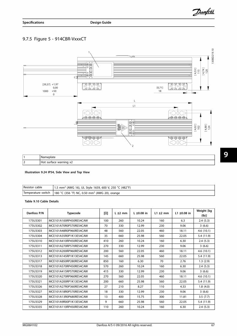
9.7.5 Figure 5 - 914CBR-VxxxCT
+1,97 0,00+50 0
[39,37]
1000
1
[ 4,7
4 ]
120
[ 4,5
3 ]
115
2
[0,71]18
L
L1
[ 4,0
2 ]
102
[ 4,8
8 ]
124
130B
D21
9.10
1 Nameplate
2 Hot surface warning x2
Illustration 9.24 IP54, Side View and Top View
Resistor cable 1.5 mm2 (AWG 16), UL Style 1659, 600 V, 250 °C (482°F)
Temperature switch 180 °C (356 °F) NC, 0.50 mm2 (AWG 20), orange
Table 9.10 Cable Details
Danfoss P/N Typecode [Ω] L ±2 mm L ±0.08 in L1 ±2 mm L1 ±0.08 inWeight [kg
(lb)]
175U3301 MCE101A100RP450RE54CAW 100 260 10.24 160 6.3 2.4 (5.3)
175U3302 MCE101A70R0P570RE54CAW 70 330 12.99 230 9.06 3 (6.6)
175U3303 MCE101A48R0P960RE54CAW 48 560 22.05 460 18.11 4.6 (10.1)
175U3304 MCE101A35R0P1K13E54CAW 35 660 25.98 560 22.05 5.4 (11.9)
175U3310 MCE101A410RP450RE54CAW 410 260 10.24 160 6.30 2.4 (5.3)
175U3311 MCE101A270RP570RE54CAW 270 330 12.99 230 9.06 3 (6.6)
175U3312 MCE101A200RP960RE54CAW 200 560 22.05 460 18.11 4.6 (10.1)
175U3313 MCE101A145RP1K13E54CAW 145 660 25.98 560 22.05 5.4 (11.9)
175U3317 MCE101A850RP280RE54CAW 850 160 6.30 70 2.76 1.3 (2.9)
175U3318 MCE101A570RP450RE54CAW 570 260 10.24 160 6.30 2.4 (5.3)
175U3319 MCE101A415RP570RE54CAW 415 330 12.99 230 9.06 3 (6.6)
175U3320 MCE101A270RP960RE54CAW 270 560 22.05 460 18.11 4.6 (10.1)
175U3321 MCE101A200RP1K13E54CAW 200 660 25.98 560 22.05 5.4 (11.9)
175U3326 MCE101A27R0P360RE54CAW 27 210 8.27 110 4.33 1.8 (4.0)
175U3327 MCE101A18R0P570RE54CAW 18 330 12.99 230 9.06 3 (6.6)
175U3328 MCE101A13R0P680RE54CAW 13 400 15.75 300 11.81 3.5 (7.7)
175U3329 MCE101A9R00P1K13E54CAW 9 660 25.98 560 22.05 5.4 (11.9)
175U3335 MCE101A110RP450RE54CAW 110 260 10.24 160 6.30 2.4 (5.3)
Specifications Design Guide
MG06H102 Danfoss A/S © 09/2016 All rights reserved. 67
9 9

Danfoss P/N Typecode [Ω] L ±2 mm L ±0.08 in L1 ±2 mm L1 ±0.08 inWeight [kg
(lb)]
175U3336 MCE101A80R0P570RE54CAW 80 330 12.99 230 9.06 3 (6.6)
175U3337 MCE101A56R0P680RE54CAW 56 400 15.75 300 11.81 3.5 (7.7)
175U3338 MCE101A38R0P1K13E54CAW 38 660 25.98 560 22.05 5.4 (11.9)
175U3343 MCE101A145RP450RE54CAW 145 260 10.24 160 6.30 2.4 (5.3)
175U3344 MCE101A100RP570RE54CAW 100 330 12.99 230 9.06 3 (6.6)
175U3345 MCE101A72R0P680RE54CAW 72 400 15.75 300 11.81 3.5 (7.7)
175U3346 MCE101A52R0P1K13E54CAW 52 660 25.98 560 22.05 5.4 (11.9)
175U3351 MCE101A72R0P1K13E54CAW 72 660 25.98 560 22.05 5.4 (11.9)
175U3360 MCE101A105RP790RE54CAW 105 460 18.11 360 14.17 3.9 (8.6)
Table 9.11 Mechanical Dimensions
130B
D22
0.10
Illustration 9.25 IP54, End View, Connection Box
[0,94] 24
[0,26] 6,5
[1,89] 48[2,52] 64
[0,4
7]
12
[0,55] 14
130B
D22
3.10
Illustration 9.26 Mounting Hole
1
130B
D22
2.10
1 PE Male Fast-On tab 6.3x0.8
Illustration 9.27 IP54, 3D View
Mechanical mounting (see Illustration 9.28):• Vertical with connection box down, or
• Horizontal
130B
D22
1.10
Illustration 9.28 Mechanical Mounting
Specifications VLT® Brake Resistor MCE 101
68 Danfoss A/S © 09/2016 All rights reserved. MG06H102
99

9.7.6 Figure 6 - 914CBR-VxxxBT
130B
D21
3.101
2
[ L+2,83 ]L+72
[0,71]18
L
L1
[ 4,7
4 ]
120
[ 4,5
3 ]
115
[ 4,0
2 ]
102
[ 4,8
8 ]
124
1 Nameplate
2 Hot surface warning x2
Illustration 9.29 IP65, Side View and Top View
Danfoss P/N Typecode [Ω] L ±2 mm L ±0.08 in L1 ±2 mm L1 ±0.08 inWeight [kg
(lb)]
175U3010 MCE101A200RP360RE65TAW 200 210 8.27 110 4.33 1.8 (4.0)
175U3013 MCE101A145RP450RE65TAW 145 260 10.24 160 6.3 2.4 (5.3)
175U3015 MCE101A145RP280RE65TAW 145 160 6.3 70 2.76 1.3 (2.9)
175U3018 MCE101A110RP360RE65TAW 110 210 8.27 110 4.33 1.8 (4.0)
175U3020 MCE101A105RP570RE65TAW 105 330 12.99 230 9.06 3 (6.6)
175U3023 MCE101A80R0P450RE65TAW 80 260 10.4 160 6.3 2.4 (5.3)
175U3025 MCE101A72R0P960RE65TAW 72 560 22.05 460 18.11 4.6 (10.1)
175U3028 MCE101A56R0P680RE65TAW 56 400 15.75 300 11.81 3.5 (7.7)
175U3030 MCE101A52R0P1K29E65TAW 52 760 29.92 660 25.98 6.1 (13.4)
175U3035 MCE101A38R0P1K13E65TAW 38 660 25.98 560 22.05 5.4 (11.9)
175U3042 MCE101A27R0P280RE65TAW 27 160 6.3 70 2.76 1.3 (2.9)
175U3054 MCE101A18R0P450RE65TAW 18 260 10.24 160 6.3 2.4 (5.3)
175U3060 MCE101A13R0P680RE65TAW 13 400 15.75 300 11.81 3.5 (7.7)
175U3069 MCE101A9R00P1K13E65TAW 9 660 25.98 560 22.05 5.4 (11.9)
175U3103 MCE101A1K20P360RE65TAW 1200 210 8.27 110 4.3 1.8 (4.0)
175U3105 MCE101A850RP280RE65TAW 850 160 6.3 70 2.76 1.3 (2.9)
175U3109 MCE101A630RP360RE65TAW 630 210 8.27 110 4.33 1.8 (4.0)
175U3111 MCE101A570RP570RE65TAW 570 330 12.99 230 9.06 3 (6.6)
Specifications Design Guide
MG06H102 Danfoss A/S © 09/2016 All rights reserved. 69
9 9

Danfoss P/N Typecode [Ω] L ±2 mm L ±0.08 in L1 ±2 mm L1 ±0.08 inWeight [kg
(lb)]
175U3113 MCE101A415RP790RE65TAW 415 460 18.11 360 14.17 3.9 (8.6)
175U3115 MCE101A410RP570RE65TAW 410 330 12.99 230 9.06 3 (6.6)
175U3117 MCE101A270RP790RE65TAW 270 460 18.11 360 14.17 3.9 (8.6)
175U3119 MCE101A270RP1K13E65TAW 270 660 25.98 560 22.05 5.4 (11.9)
175U3121 MCE101A200RP1K13E65TAW 200 660 25.98 560 22.05 5.4 (11.9)
175U3125 MCE101A145RP450RE65TAW 145 260 10.24 160 6.3 2.4 (5.3)
175U3137 MCE101A100RP570RE65TAW 100 330 12.99 230 9.06 3 (6.6)
175U3145 MCE101A70R0P790RE65TAW 70 460 18.11 360 14.17 3.9 (8.6)
175U3401 MCE101A100RP450RE65TAW 100 260 10.24 160 6.3 2.4 (5.3)
175U3403 MCE101A70R0P570RE65TAW 70 330 12.99 230 9.06 3 (6.6)
175U3405 MCE101A48R0P960RE65TAW 48 560 22.05 460 18.11 4.6 (10.1)
175U3407 MCE101A35R0P1K13E65TAW 35 660 25.98 560 22.05 5.4 (11.9)
175U3415 MCE101A410RP450RE65TAW 410 260 10.24 160 6.3 2.4 (5.3)
175U3417 MCE101A270RP570RE65TAW 270 330 12.99 230 9.06 3 (6.6)
175U3419 MCE101A200RP960RE65TAW 200 560 22.05 460 18.11 4.6 (10.1)
175U3421 MCE101A145RP1K13E65TAW 145 660 25.98 560 22.05 5.4 (11.9)
175U3429 MCE101A570RP450RE65TAW 570 260 10.24 160 6.3 2.4 (5.3)
175U3431 MCE101A415RP570RE65TAW 415 330 12.99 230 6.09 3 (6.6)
175U3433 MCE101A270RP960RE65TAW 270 560 22.05 460 18.11 4.6 (10.1)
175U3435 MCE101A200RP1K13E65TAW 200 660 25.98 560 22.05 5.4 (11.9)
175U3441 MCE101A18R0P570RE65TAW 18 330 12.99 230 9.06 3 (6.6)
175U3449 MCE101A110RP450RE65TAW 110 260 10.24 160 6.3 2.4 (5.3)
175U3451 MCE101A80R0P570RE65TAW 80 330 12.99 230 9.06 3 (6.6)
175U3455 MCE101A72R0P680RE65TAW 72 400 15.75 300 11.81 3.5 (7.7)
175U3457 MCE101A52R0P1K13E65TAW 52 660 25.98 560 22.05 5.4 (11.9)
175U3465 MCE101A72R0P1K13E65TAW 72 660 25.98 560 22.05 5.4 (11.9)
175U3478 MCE101A27R0P360RE65TAW 27 210 8.27 110 4.33 1.8 (4.0)
175U3482 MCE101A105RP790RE65TAW 105 460 18.11 360 14.17 3.9 (8.6)
Table 9.12 Mechanical Dimensions
130B
D21
4.10
[2,2
2 ]
56
1
1 Torque 2–3 Nm (17.71–26.57 lb-in)
Illustration 9.30 IP65, End View, Connection Box
[2,52] 64
[1,89] 48
[0,26] 6,5
[0,55] 14
[0,94] 24
[0,4
7]
12 130B
D21
8.10
Illustration 9.31 Mounting Hole
Specifications VLT® Brake Resistor MCE 101
70 Danfoss A/S © 09/2016 All rights reserved. MG06H102
99

130B
D21
5.10
13
2
4
5
1 PE M4Torque 2–3 Nm (17.71–26.57 lb-in)
2 Temperature switch connection:Marked T1/T2Type: Phoenix G5/2 with screw connection
IEC: 0.2–4 mm2/500 VUL: AWG 24–12/300 VWire stripping: 8 mm (0.31 in)Torque: 0.7 Nm (6.2 lb-in)
3 For temperature switch cable:Clamping range: 3.5–7.0 mm (0.14–0.28 lb-in)
4 For resistor cable:Cable gland with internal connection for braidClamping range: 9.0–16.5 mm (0.35–0.65 in)
5 Resistor connection:Marked RB1/RB2Type: PHOENIX G10/2
IEC: 0.5–10 mm2/800 VUL: AWG 20–6/600 VWire stripping: 12 mm (0.47 in)Torque: 1.5–1.8 Nm (13.28–15.94 lb-in)
Illustration 9.32 Connection Box
130B
D21
7.10
Illustration 9.33 IP65, 3D View
Mechanical mounting (see Illustration 9.34):• Vertical with connection box down, or
• Horizontal
130B
D21
6.10
Illustration 9.34 Mechanical Mounting
Specifications Design Guide
MG06H102 Danfoss A/S © 09/2016 All rights reserved. 71
9 9

9.7.7 Figure 7 - 914CCHxxxCT
130B
D24
2.10
1
2
[0.93] 23.5
[2.3
6]
60
[0.93] 23.5 L1
L
L1 L1
L
[2.3
6]
60
[0.19] 4.8
[0.19] 4.8
+_ 0.010.2+_
+_ 0.010.2+_
39.37+ 1.97 0.00
+50 01000
39.37+ 1.97 0.00
+50 01000
1 Supplier marking
2 Supplier marking
Illustration 9.35 IP54, Side View and Top View
Resistor cable 1.5 mm2 (AWG 16), UL Style 1659, 600 V, 250 °C (482 °F)
Temperature switch 180 °C (356 °F) NC, 0.50 mm2 (AWG 20), orange
Table 9.13 Cable Details
Danfoss P/N Typecode [Ω] L ±2 mm L ±0.08 inL1 ±0.5
mmL1 ±0.02 in
Weight [kg(lb)]
175U3000 MCE101A1K20P100RE54CAW 1200 145 5.71 98 3.86 0.27 (0.6)
175U3001 MCE101A850RP100RE54CAW 850 145 5.71 98 3.86 0.27 (0.6)
175U3002 MCE101A630RP100RE54CAW 630 145 5.71 98 3.86 0.27 (0.6)
175U3003 MCE101A570RP100RE54CAW 570 145 5.71 98 3.86 0.27 (0.6)
175U3004 MCE101A410RP100RE54CAW 410 145 5.71 98 3.86 0.27 (0.6)
175U3005 MCE101A415RP200RE54CAW 415 251 9.8 204 8.03 0.54 (1.2)
175U3006 MCE101A300RP100RE54CAW 300 145 5.71 98 3.86 0.27 (0.6)
175U3007 MCE101A270RP200RE54CAW 270 251 9.8 204 8.03 0.54 (1.2)
175U3008 MCE101A200RP200RE54CAW 200 251 9.8 204 8.03 0.54 (1.2)
175U3011 MCE101A200RP100RE54CAW 200 145 5.71 98 3.86 0.27 (0.6)
175U3016 MCE101A145RP100RE54CAW 145 145 5.71 98 3.86 0.27 (0.6)
175U3021 MCE101A100RP100RE54CAW 100 145 5.71 98 3.86 0.27 (0.6)
175U3026 MCE101A70R0P200RE54CAW 70 251 9.8 204 8.03 0.54 (1.2)
175U3031 MCE101A48R0P200RE54CAW 48 251 9.8 204 8.03 0.54 (1.2)
175U3036 MCE101A35R0P200RE54CAW 35 251 9.8 204 8.03 0.54 (1.2)
175U3096 MCE101A300RP200RE54CAW 300 251 9.8 204 8.03 0.54 (1.2)
Specifications VLT® Brake Resistor MCE 101
72 Danfoss A/S © 09/2016 All rights reserved. MG06H102
99

Danfoss P/N Typecode [Ω] L ±2 mm L ±0.08 inL1 ±0.5
mmL1 ±0.02 in
Weight [kg(lb)]
175U3101 MCE101A1K20P200RE54CAW 1200 251 9.8 204 8.03 0.54 (1.2)
175U3300 MCE101A145RP300RE54CAW 145 355 13.98 154 (x2) 6.06 (x2) 1.58 (3.5)
175U3308 MCE101A850RP200RE54CAW 850 251 9.8 204 8.03 0.54 (1.2)
175U3309 MCE101A630RP300RE54CAW 630 355 13.98 154 (x2) 6.06 (x2) 1.58 (3.5)
175U3325 MCE101A35R0P300RE54CAW 35 355 13.98 154 (x2) 6.06 (x2) 1.58 (3.5)
175U3342 MCE101A200RP300RE54CAW 200 355 13.98 154 (x2) 6.06 (x2) 1.58 (3.5)
175U3361 MCE101A270RP300RE54CAW 270 355 13.98 154 (x2) 6.06 (x2) 1.58 (3.5)
Table 9.14 Mechanical Dimensions
[2.52] 64
[2.99] 76
[0.15]3.7[0
.59]
15
130B
D24
3.10
Illustration 9.36 IP54, End View Cable End
130B
D24
5.12
1
1PEMale fast-onTab 6.3x0.8
Illustration 9.37 IP54, 3D View
Mechanical mounting (see Illustration 9.38):• Vertical with cables down, or
• Horizontal
130B
D24
4.10
Illustration 9.38 Mechanical Mounting
Specifications Design Guide
MG06H102 Danfoss A/S © 09/2016 All rights reserved. 73
9 9

9.7.8 Figure 8 - 917CM13
175Uxxxx
6
8
3 4
30 [ 1.2 ]
45 [1.8]
160
[6.3
]
85 [3
.3]
30 [1
.2]
130B
D24
6.10
Illustration 9.39 IP20, Side View, Right
1 Resistor
2 Terminal board, see Illustration 9.42
3 Cable gland for load cables
4 Cable gland M16 temperature switch cable
5 Grounding bolt M6
6 Nameplate/warning signs
7 Front cover IP20
8 Back cover IP20
9 Top cover IP20
10 Temperature switch 260 °C (500 °F) (NC)
11 Load connection, 2x bolt M8
12 Auxiliary connection for temperature switch, porcelain
clamp 2.5 mm2
13 4x fixing hole Ø 9 mm (0.35 in)
Table 9.15 Legend to Illustration 9.39 to Illustration 9.43
Danfoss P/N Type codeResistance
[Ω]Cable gland type for load
terminalsWeight[kg (lb)]
175U3236 MCE101C38R0P5K00E20BAW 38 M25 15 (33)
Table 9.16 Mechanical Dimensions
130B
D24
7.10
1
2
302 [ 11.9 ]
330 [ 13.0 ]
2 3
4
5
7
10
13 13
1
5
7
Illustration 9.40 IP20, Front View
130B
D24
8.10
380 [ 15.0 ]
300
[ 11.
8 ]
480 [ 18.9 ]
13
7
Illustration 9.41 IP20, Side View, Left
Specifications VLT® Brake Resistor MCE 101
74 Danfoss A/S © 09/2016 All rights reserved. MG06H102
99

11
12
44 [ 1.7 ]
11
12
60 [ 2.4 ]
70 [
2.8
]
130B
D24
9.10
Illustration 9.42 Connections
7
8
9
10
130B
D25
0.10
Illustration 9.43 IP20, Top View
Specifications Design Guide
MG06H102 Danfoss A/S © 09/2016 All rights reserved. 75
9 9

9.7.9 Figure 9 - 917CM15
175Uxxxx
6
8
3 4
30 [ 1.2 ]
45 [1.8]
160
[6.3
]
85 [3
.3]
30 [1
.2]
130B
D24
6.10
Illustration 9.44 IP20, Side View, Right
1 Resistor
2 Terminal board, see Illustration 9.47
3 Cable gland for load cables
4 Cable gland M16 temperature switch cable
5 Grounding bolt M6
6 Nameplate/warning signs
7 Front cover IP20
8 Back cover IP20
9 Top cover IP20
10 Temperature switch 260 °C (500 °F) (NC)
11 Load connection, 2x bolt M8
12 Auxiliary connection for temperature switch, porcelain
clamp 2.5 mm2
13 4x fixing hole Ø 9 mm (0.35 in)
Table 9.17 Legend to Illustration 9.44 to Illustration 9.47
Danfoss P/N Type code Resistance [Ω]Cable gland type for load
terminalsWeight [kg (lb)]
175U3067 MCE101C9R10P9K00E20BAW 9.1 M40 21 (46)
175U3079 MCE101C4R70P9K00E20BAW 4.7 M40 21 (46)
175U3200 MCE101C27R0P10K0E20BAW 27.0 M25 22 (49)
175U3203 MCE101C19R0P10K0E20BAW 19.0 M25 20 (44)
175U3231 MCE101C5R50P7K00E20BAW 5.5 M32 19 (42)
175U3232 MCE101C11R0P7K00E20BAW 11 M25 19 (42)
175U3233 MCE101C5R70P6K00E20BAW 5.7 M25 19 (42)
175U3234 MCE101C5R70P8K00E20BAW 5.7 M25 20 (44)
175U3235 MCE101C3R50P9K00E20BAW 3.5 M25 21 (46)
175U3237 MCE101C28R0P6K00E20BAW 28 M25 19 (42)
175U3238 MCE101C22R0P8K00E20BAW 22 M25 20 (44)
175U3239 MCE101C38R0P6K00E20BAW 38 M25 19 (42)
175U3240 MCE101C31R0P8K00E20BAW 31 M25 20 (44)
175U3242 MCE101C52R0P6K00E20BAW 52 M25 19 (42)
175U3243 MCE101C42R0P8K00E20BAW 42 M25 20 (44)
175U3244 MCE101C31R0P10K0E20BAW 31 M25 22 (49)
175U3245 MCE101C7R00P7K00E20BAW 7 M32 20 (44)
Table 9.18 Mechanical Dimensions
1
2
Thermocontact260 °C (NC)
260°C
502 [ 19.8 ]
530 [ 20.9 ]
23
4
57
10
13 13
1
5
130B
D25
2.10
Illustration 9.45 IP20, Front View
Specifications VLT® Brake Resistor MCE 101
76 Danfoss A/S © 09/2016 All rights reserved. MG06H102
99

130B
D24
8.10
380 [ 15.0 ]
300
[ 11.
8 ]
480 [ 18.9 ]
13
7
Illustration 9.46 IP20, Side View, Left
11
12
44 [ 1.7 ]
11
12
60 [ 2.4 ]
70 [
2.8
]
130B
D24
9.10
Illustration 9.47 Connections
8
7
9
10
130B
D25
5.10
Illustration 9.48 IP20, Top View
Specifications Design Guide
MG06H102 Danfoss A/S © 09/2016 All rights reserved. 77
9 9

9.7.10 Figure 10 - 917CM17
130B
D25
6.10
148
175Uxxxx
6
3
4
45 [1.8]
235
[9.3
]
160
[6.3
]
85 [3
.3]
30 [1.2]
30 [1
.2]
Illustration 9.49 IP20, Side View, Right
1 Resistor
2 Terminal board, see Illustration 9.52
3 Cable gland for load cables
4 Cable gland M16 temperature switch cable
5 Grounding bolt M6
6 Nameplate/warning signs
7 Front cover IP20
8 Back cover IP20
9 Top cover IP20
10 Temperature switch 260 °C (500 °F) (NC)
11 Load connection, 2x bolt M8
12 Auxiliary connection for temperature switch, porcelain
clamp 2.5 mm2
13 4x fixing hole Ø 9 mm (0.35 in)
14 Second cable gland. Not in use.
Table 9.19 Legend to Illustration 9.49 to Illustration 9.53
Danfoss P/N Type codeResistance
[Ω]Cable gland type for load terminals
Weight [kg(lb)]
175U3072 MCE101C7R40P11K0E20BAW 7.4 M40 24 (53)
175U3075 MCE101C6R10P13K0E20BAW 6.1 M50 25 (55)
175U3083 MCE101C3R70P11K0E20BAW 3.7 M50 24 (53)
175U3084 MCE101C3R30P13K0E20BAW 3.3 2xM25 25 (55)
175U3201 MCE101C27R0P14K0E20BAW 27.0 M25 25 (55)
175U3204 MCE101C19R0P14K0E20BAW 19 M25 25 (55)
175U3206 MCE101C14R0P14K0E20BAW 14.0 M32 25 (55)
175U3224 MCE101C3R50P14K0E20BAW 3.5 M40 25 (55)
Table 9.20 Mechanical Dimensions
260°C
1
2
Thermocontact260 °C (NC)
712[28.0]
740[29.1]
132
5
7 1
10
4
35
13
130B
D25
7.10
Illustration 9.50 IP20, Front View
130B
D24
8.10
380 [ 15.0 ]
300
[ 11.
8 ]
480 [ 18.9 ]
13
7
Illustration 9.51 IP20, Side View, Left
Specifications VLT® Brake Resistor MCE 101
78 Danfoss A/S © 09/2016 All rights reserved. MG06H102
99

11
12
44 [ 1.7 ]
11
12
60 [ 2.4 ]
70 [
2.8
]
130B
D24
9.10
Illustration 9.52 Connections
8
7 10
9
130B
D26
0.10
Illustration 9.53 IP20, Top View
Specifications Design Guide
MG06H102 Danfoss A/S © 09/2016 All rights reserved. 79
9 9

9.7.11 Figure 11 - 917CM25
8
6
14
4
3
30 [1.2]
30 [1
.2]
85 [3
.3]
160
[6.3
]
235
[9.3
]
45 [1.8]
175Uxxxx
130B
D26
1.10
Illustration 9.54 IP20, Side View, Right
1 Resistor
2 Terminal board, see Illustration 9.57
3 Cable gland for load cables
4 Cable gland M16 temperature switch cable
5 Grounding bolt M6
6 Nameplate/warnings signs
7 Front cover IP20
8 Back cover IP20
9 Top cover IP20
10 Temperature switch 260 °C (500 °F) (NC)
11 Load connection, 2x bolt M8
12 Auxiliary connection for temperature switch, porcelain
clamp 2.5 mm 2
13 4x fixing hole Ø 9 mm (0.35 in)
14 Second cable gland. Not in use.
Table 9.21 Legend to Illustration 9.54 to Illustration 9.58
Danfoss P/N Type code Resistance [Ω]Cable gland type for load
terminalsWeight [kg (lb)]
175U3078 MCE101C5R00P16K0E20BAW 5.0 2xM25 35 (77)
175U3082 MCE101C4R00P20K0E20BAW 4.0 2xM32 37 (82)
175U3088 MCE101C2R70P16K0E20BAW 2.7 2xM32 35 (77)
175U3091 MCE101C2R10P20K0E20BAW 2.1 2xM40 37 (82)
175U3202 MCE101C22K0P17K0E20BAW 22.0 M25 35 (77)
175U3207 MCE101C14R0P17K0E20BAW 14.0 M32 35 (77)
175U3210 MCE101C12R0P17K0E20BAW 12.0 M32 35 (77)
175U3227 MCE101C2R80P17K0E20BAW 2.8 M40 35 (77)
Table 9.22 Mechanical Dimensions
Specifications VLT® Brake Resistor MCE 101
80 Danfoss A/S © 09/2016 All rights reserved. MG06H102
99
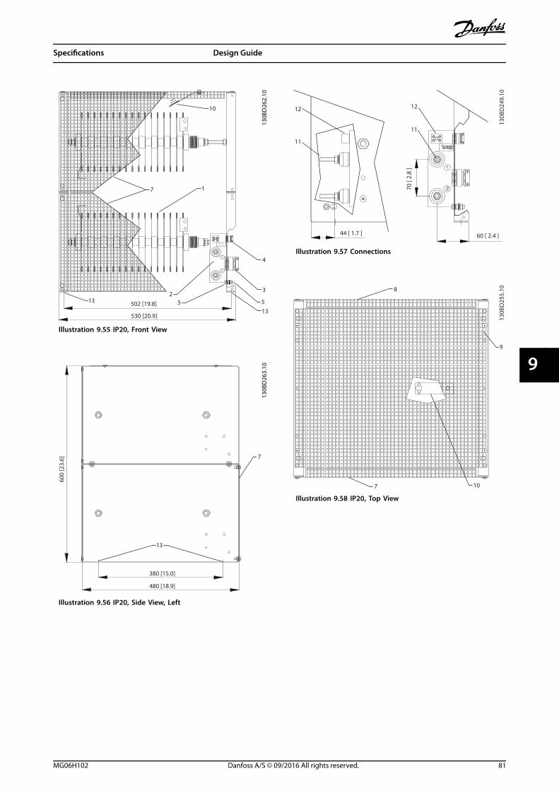
260°C
1
2
Thermocontact
260 °C (NC)
10
7 1
4
3
513
132
5502 [19.8]
530 [20.9]
130B
D26
2.10
Illustration 9.55 IP20, Front View
13
380 [15.0]
480 [18.9]
600
[23.
6] 7
130B
D26
3.10
Illustration 9.56 IP20, Side View, Left
11
12
44 [ 1.7 ]
11
12
60 [ 2.4 ]
70 [
2.8
]
130B
D24
9.10
Illustration 9.57 Connections
8
7
9
10
130B
D25
5.10
Illustration 9.58 IP20, Top View
Specifications Design Guide
MG06H102 Danfoss A/S © 09/2016 All rights reserved. 81
9 9

9.7.12 Figure 12 - 917CM27
8
6
14
4
3
30 [1.2]
30 [1
.2]
85 [3
.3]
160
[6.3
]
235
[9.3
]
45 [1.8]
175Uxxxx
130B
D26
1.10
Illustration 9.59 IP20, Side View, Right
1 Resistor
2 Terminal board, see Illustration 9.62
3 Cable gland for load cables
4 Cable gland M16 temperature switch cable
5 Grounding bolt M6
6 Nameplate/warning signs
7 Front cover IP20
8 Back cover IP20
9 Top cover IP20
10 Temperature switch 260 °C (500 °F) (NC)
11 Load connection, 2x bolt M8
12 Auxiliary connection for temperature switch, porcelain
clamp 2.5 mm2
13 4x fixing hole Ø 9 mm (0.35 in)
14 Second cable gland. Not in use.
Table 9.23 Legend to Illustration 9.59 to Illustration 9.63
Danfoss P/N Typecode Resistance [Ω]Cable gland type for
load terminalsWeight [kg (lb)]
175U3085 MCE101C3R30P26K0E20BAW 3.3 2xM32 45 (99)
175U3089 MCE101C2R50P32K0E20BAW 2.5 2xM50 48 (106)
175U3093 MCE101C1R70P26K0E20BAW 1.7 2xM50 45 (99)
175U3097 MCE101C1R30P32K0E20BAW 1.3 2xM50 48 (106)
175U3205 MCE101C15R5P21K0E20BAW 15.5 M32 41 (90)
175U3208 MCE101C13R5P21K0E20BAW 13.5 M32 41 (90)
175U3209 MCE101C13R5P26K0E20BAW 13.5 M32 45 (99)
175U3211 MCE101C11R0P26K0E20BAW 11.0 M32 45 (99)
175U3213 MCE101C9R50P21K0E20BAW 9.5 M32 41 (90)
175U3216 MCE101C7R00P26K0E20BAW 7.0 M40 45 (99)
175U3241 MCE101C7R00P30K0E20BAW 7.0 M40 52 (115)
Table 9.24 Mechanical Dimensions
Specifications VLT® Brake Resistor MCE 101
82 Danfoss A/S © 09/2016 All rights reserved. MG06H102
99

260°C
1
2
Thermocontact260 °C (NC)
10
7 1
132
5
4
3
5
13712[28.0]
740[29.1]
130B
D26
7.10
Illustration 9.60 IP20, Front View
13
380 [15.0]
480 [18.9]
600
[23.
6] 7
130B
D26
3.10
Illustration 9.61 IP20, Side View, Left
11
12
44 [ 1.7 ]
11
12
60 [ 2.4 ]
70 [
2.8
]
130B
D24
9.10
Illustration 9.62 Connections
8
7 10
9
130B
D26
0.10
Illustration 9.63 IP20, Top View
Specifications Design Guide
MG06H102 Danfoss A/S © 09/2016 All rights reserved. 83
9 9

9.7.13 Figure 13 - 917CM37
130B
D27
1.10
175Uxxxx
8
6
160
[ 6.3
]
60 [
2.4
]
25 [ 1.0 ]
30 [ 1.2 ]
4 3
90 [ 3.5 ]
14
100
[ 3.9
]
100 [ 3.9 ]
Illustration 9.64 IP20, Side View, Right
1 Resistor
2 Terminal board, see Illustration 9.67
3 Cable gland for load cables
4 Cable gland M16 temperature switch cable
5 Grounding bolt M10
6 Nameplate/warning signs
7 Front cover IP20
8 Back cover IP20
9 Top cover IP20
10 Temperature switch 260 °C (500 °F) (NC)
11 Load connection, 2x bolt M8
12 Auxiliary connection for temperature switch, porcelain
clamp 2.5 mm2
13 4x fixing hole Ø 9 mm (0.35 in)
14 Second cable gland. Not in use.
Table 9.25 Legend to Illustration 9.64 to Illustration 9.68
Danfoss P/N Type code Resistance [Ω]Cable gland type for load
terminalsWeight [kg (lb)]
175U3090 MCE101C2R30P36K0E20BAW 2.3 2xM50 74 (163)
175U3092 MCE101C2R00P42K0E20BAW 2.0 2xM50 78 (172)
175U3098 MCE101C1R20P36K0E20BAW 1.2 2xM50 74 (163)
175U3099 MCE101C1R10P42K0E20BAW 1.1 2xM50 78 (172)
175U3212 MCE101C11R0P36K0E20BAW 11.0 M32 74 (163)
175U3214 MCE101C9R10P42K0E20BAW 9.1 M40 78 (172)
175U3217 MCE101C7R00P36K0E20BAW 7.0 M50 74 (163)
175U3219 MCE101C5R50P36K0E20BAW 5.5 M40 74 (163)
175U3221 MCE101C4R70P42K0E20BAW 4.7 M40 78 (172)
Table 9.26 Mechanical Dimensions
Specifications VLT® Brake Resistor MCE 101
84 Danfoss A/S © 09/2016 All rights reserved. MG06H102
99

Thermocontact260 °C (NC)
1 2
260°C
10
1
7
3/4
5
13
12211
13 712 [28.0]740 [29.1]
130B
D27
2.10
Illustration 9.65 IP20, Front View
130B
D27
3.10
7
380 [ 15.0 ]480 [ 18.9 ]
13
1020
[ 40
.2 ]
Illustration 9.66 IP20, Side View, Left
Thermocontact260 °C (NC)
1 2
97.5
[3.8
]
73.5 [2.9]
11
1235 [1.4]
224.5 [8.8] 100 [3.9]
11 12
130B
D27
4.10
Illustration 9.67 Connections
8
7 10
9
130B
D26
0.10
Illustration 9.68 IP20, Top View
Specifications Design Guide
MG06H102 Danfoss A/S © 09/2016 All rights reserved. 85
9 9

9.7.14 Figure 14 - 917CMD27
130B
D27
6.10
175Uxxxx
8
6
160
[ 6.3
]60
[ 2.
4 ]
25 [ 1.0 ]
30 [ 1.2 ]
4 3
90 [ 3.5 ]
3
100
[ 3.9
]
100 [ 3.9 ]
Illustration 9.69 IP20, Side View, Right
1 Resistor
2 Terminal board, see Illustration 9.72
3 Cable gland for load cables
4 Cable gland M16 temperature switch cable
5 Grounding bolt M10
6 Nameplate/warning signs
7 Front cover IP20
8 Back cover IP20
9 Top cover IP20
10 Temperature switch 260 °C (500 °F) (NC)
11 Load connection, 2xbolt M8
12 Auxiliary connection for temperature switch, porcelain
clamp 2.5 mm2
13 6 x fixing hole Ø 9 mm (0.35 in)
Table 9.27 Legend to Illustration 9.69 to Illustration 9.73
Danfoss P/N Type code Resistance [Ω]Cable gland type for load
terminalsWeight [kg (lb)]
175U3094 MCE101C1R60P52K0E20BAW 1.6 2xM50 90 (198)
175U3095 MCE101C1R40P60K0E20BAW 1.4 2xM50 90 (198)
175U3215 MCE101C7R40P52K0E20BAW 7.4 M40 90 (198)
175U3218 MCE101C6R10P60K0E20BAW 6.1 M50 90 (198)
175U3223 MCE101C3R70P52K0E20BAW 3.7 M50 90 (198)
175U3225 MCE101C3R30P60K0E20BAW 3.3 2xM25 90 (198)
Table 9.28 Mechanical Dimensions
Thermocontact260 °C (NC)
1 2
10
13
12211
3/4
5
13
17
712 [28.0]740 [29.1]
130B
D27
7.10
Illustration 9.70 IP20, Front View
130B
D27
8.10
7
770 [ 30.3 ]
870 [ 34.3 ]
13
720
[ 28.
3 ]
Illustration 9.71 IP20, Side View, Left
Specifications VLT® Brake Resistor MCE 101
86 Danfoss A/S © 09/2016 All rights reserved. MG06H102
99

Thermocontact260 °C (NC)
1 2
97.5
[3.8
]
73.5 [2.9]
11
1235 [1.4]
224.5 [8.8] 100 [3.9]
11 12
130B
D27
4.10
Illustration 9.72 Connections
7
10
9
813
0BD
280.
10
Illustration 9.73 IP20, Top View
Specifications Design Guide
MG06H102 Danfoss A/S © 09/2016 All rights reserved. 87
9 9

9.7.15 Figure 15 - 917CMD37
130B
D28
1.10
175Uxxxx
8
6
160
[ 6.3
]60
[ 2.
4 ]
25 [ 1.0 ]
30 [ 1.2 ]
4 3
90 [ 3.5 ]
3
100
[ 3.9
]
100 [ 3.9 ]
Illustration 9.74 IP20, Side View, Right
1 Resistor
2 Terminal board, see Illustration 9.77
3 Cable gland for load cables
4 Cable gland M16 temperature switch cable
5 Grounding bolt M10
6 Nameplate/warning signs
7 Front cover IP20
8 Back cover IP20
9 Top cover IP20
10 Temperature switch 260 °C (500 °F) (NC)
11 Load connection, 2x bolt M8
12 Auxiliary connection for temperature switch, porcelain
clamp 2.5 mm2
13 6 x fixing hole Ø 9 mm (0.35 in)
Table 9.29 Legend to Illustration 9.74 to Illustration 9.78
Danfoss P/N Type code Resistance [Ω]Cable gland type for load
terminalsWeight [kg (lb)]
175U3220 MCE101C5R00P78K0E20BAW 5.0 2xM25 182 (401)
175U3222 MCE101C4R00P90K0E20BAW 4.0 2xM32 190 (419)
175U3228 MCE101C2R70P78K0E20BAW 2.7 2xM32 182 (401)
175U3230 MCE101C2R10P90K0E20BAW 2.1 2xM40 190 (419)
Table 9.30 Mechanical Dimensions
Specifications VLT® Brake Resistor MCE 101
88 Danfoss A/S © 09/2016 All rights reserved. MG06H102
99

Thermocontact260 °C (NC)
1 2
260°C
10
1
7
3/4
5
13
12211
13 712 [28.0]740 [29.1]
130B
D27
2.10
Illustration 9.75 IP20, Front View
130B
D28
3.10
7
770 [ 30.3 ]870 [ 34.3 ]
13
1020
[ 40
.2 ]
Illustration 9.76 IP20, Side View, Left
Thermocontact260 °C (NC)
1 2
97.5
[3.8
]
73.5 [2.9]
11
1235 [1.4]
224.5 [8.8] 100 [3.9]
11 12
130B
D27
4.10
Illustration 9.77 Connections
7
10
9
8
130B
D28
0.10
Illustration 9.78 IP20, Top View
Specifications Design Guide
MG06H102 Danfoss A/S © 09/2016 All rights reserved. 89
9 9

9.7.16 Figure 16 - 929CBT-VxxxGHT
130B
D29
2.10
[L + 8.82] L + 224
L
L1
[0.53] 13.5
L
1
2
[9.8
8]25
1
[11.
02]
280
[10.
63]
270
[11.
81]
300
[0.3
3]8.
5
1 Hot surface warning x3
2 Nameplate
Illustration 9.79 IP21, Side View and Top View
Danfoss P/NTypecode Ω
L ±2mm
L ±0.08 inL1 ±2mm
L1 ±0.08 inWeight [kg
(lb)]
175U3051 MCE101A15R5P3K50E21TAW 15.5 560 22.05 530 20.87 25.5 (56.2)
175U3057 MCE101A13R5P4K20E21TAW 13.5 660 25.98 630 24.80 29 (63.9)
175U3063 MCE101A11R0P5K50E21TAW 11 760 29.92 730 28.74 32.5 (71.7)
175U3065 MCE101A9R50P4K20E21TAW 9.5 660 25.98 630 24.80 29 (63.9)
175U3070 MCE101A7R00P5K50E21TAW 7 760 29.92 730 28.74 32.5 (71.7)
175U3134 MCE101A105RP4K20E21TAW 105 660 25.98 630 24.80 29 (63.9)
175U3142 MCE101A72R0P4K20E21TAW 72 660 25.98 630 24.80 29 (63.9)
175U3148 MCE101A52R0P5K50E21TAW 52 760 29.92 730 28.74 32.5 (71.7)
175U3156 MCE101A38R0P5K50E21TAW 38 760 29.92 730 28.74 32.5 (71.7)
175U3174 MCE101A13R0P3K50E21TAW 13 560 22.05 530 20.87 25.5 (56.2)
175U3176 MCE101A9R00P5K50E21TAW 9 760 29.92 730 28.74 32.5 (71.7)
Specifications VLT® Brake Resistor MCE 101
90 Danfoss A/S © 09/2016 All rights reserved. MG06H102
99

Danfoss P/NTypecode Ω
L ±2mm
L ±0.08 inL1 ±2mm
L1 ±0.08 inWeight [kg
(lb)]
175U3178 MCE101A5R70P5K50E21TAW 5.7 760 29.92 730 28.74 32.5 (71.7)
175U3474 MCE101A15R5P4K20E21TAW 15.5 660 25.98 630 24.80 29 (63.9)
175U3476 MCE101A13R5P5K50E21TAW 13.5 760 29.92 730 28.74 32.5 (71.7)
Table 9.31 Mechanical Dimensions
130B
D29
3.10[0.79]
20
1
1 Torque 1–1.4 Nm (8.85–12.39 lb-in)
Illustration 9.80 IP21, End View, Connection Box
130B
D29
7.10[0.71]
18
[0.3
3]
8.5
[0.35] R9
Illustration 9.81 Mounting Hole
1
2
3
4
5
130B
D29
4.11
1 Resistor connection:Marked RB1/RB2Type: ENSTO KE 66
IEC: Cu 2.5–50 mm2, AI: 6–50 mm2/750 VUL: AWG 6–1/0/600 VWire stripping: 23 mm (0.9 in)Torque: 10 Nm (88.51 lb-in)
2 Temperature switch connection:Marked: T1/T2Type: PHOENIX G5/2 with screw connection
IEC: 0.2–4 mm2 500 VUL: AWG 24–12/300 VWire stripping: 8 mm (0.31 in)Torque: 0.7 Nm (6.2 lb-in)
3 For temperature switch cable:Clamping range: 3.5–7.0 mm (0.14–0.28 in)Size wrench (SW): 16 mm (0.63 in)
4 For resistor cable:Cable gland with internal connection for braidClamping range: 19–28 mmSize wrench (SW): 45 mm (1.78 in)
5 PE: M8Torque: 4.5–5.5 Nm (39.83–48.68 lb-in)
Illustration 9.82 Connection Box
Specifications Design Guide
MG06H102 Danfoss A/S © 09/2016 All rights reserved. 91
9 9

130B
D29
6.10
Illustration 9.83 IP21, 3D View
Mechanical mounting (see Illustration 9.84):• Vertical with connection box down (IP21), or
• Horizontal (IP20)
130B
D29
5.10
Illustration 9.84 Mechanical Mounting
Specifications VLT® Brake Resistor MCE 101
92 Danfoss A/S © 09/2016 All rights reserved. MG06H102
99

9.7.17 Figure 17 - 929CBT-VxxxBGHT
130B
D28
6.10
[0.53] 13.5
[9.8
8] 2
51
[11.
02]
28
0
[L + 5.31] L + 135
L
L1
L
[3.15] 80
1
2
[10.
63]
270
[0.3
3] 8
.5
[11.
81]
300
1 Hot surface warning x3
2 Nameplate
Illustration 9.85 IP65, Side View and Top View
Danfoss code Typecode ΩL ±2mm
L ±0.08 inL1 ±2mm
L1 ±0.08 inWeight [kg
(lb)]
175U3052 MCE101A15R5P3K50E65TAW 15.5 560 22.05 530 20.87 26.5 (58.4)
175U3058 MCE101A13R5P4K20E65TAW 13.5 660 25.95 630 24.8 30 (66.1)
175U3064 MCE101A11R0p5K50E65TAW 11 760 29.92 730 28.74 33.5 (73.9)
175U3066 MCE101A9R50P4K20E65TAW 9.5 660 25.95 630 24.8 30 (66.1)
175U3071 MCE101A7R00P5K50E65TAW 7 760 29.92 730 28.74 33.5 (73.9)
175U3135 MCE101A105RP4K20E65TAW 105 660 25.95 630 24.8 30 (66.1)
175U3143 MCE101A72R0P4K20E65TAW 72 660 25.95 630 24.8 30 (66.1)
175U3149 MCE101A52R0P5K50E65TAW 52 760 29.92 730 28.74 33.5 (73.9)
175U3157 MCE101A38R0P5K50E65TAW 38 760 29.92 730 28.74 33.5 (73.9)
175U3175 MCE101A13R0P3K50E65TAW 13 560 22.05 530 20.87 26.5 (58.4)
175U3177 MCE101A9R00P5K50E65TAW 9 760 29.92 730 28.74 33.5 (73.9)
Specifications Design Guide
MG06H102 Danfoss A/S © 09/2016 All rights reserved. 93
9 9

Danfoss code Typecode ΩL ±2mm
L ±0.08 inL1 ±2mm
L1 ±0.08 inWeight [kg
(lb)]
175U3179 MCE101A5R70P5K50E65TAW 5.7 760 29.92 730 28.74 33.5 (73.9)
175U3473 MCE101A15R5P4K20E65TAW 15.5 660 25.95 630 24.8 30 (66.1)
175U3475 MCE101A13R5P5K50E65TAW 13.5 760 29.92 730 28.74 33.5 (73.9)
Table 9.32 Mechanical Dimension
130B
D28
7.10
[11.85] 301
[0.79] 20
1
1 Torque 1–1.4 Nm (8.86–12.34 lb-in)
Illustration 9.86 IP65, End View, Connection Box
130B
D29
1.10[0.71]
18
[0.3
3]
8.5
[0.35] R9
Illustration 9.87 Mounting Hole
1
2
3
45
130B
D28
8.11
5
1 Temperature switch connection:Marked: T1/T2
IEC: 0.2–4 mm2/500 VUL: AWG 24–12/300 VWire stripping: 8 mm (0.31 in)Torque: 0.7 Nm (6.2 lb-in)
2 For temperature switch cable:Clamping range: 3.5–7.0 mm (0.14–0.28 in)Size wrench (SW): 16 mm (0.63 in)
3 For resistor cable:Cable gland with internal connection for braidClamping range: 19–28 mm (0.74–1.1 in)Size wrench (SW): 45 mm (1.78)
4 PE: M8Torque 4.5–5.5 Nm (39.83–48.68 lb-in)
5 Resistor connection:Marked RB1/RB2
IEC: Cu 2.5–50 mm2, AI: 6–50 mm2/750 VUL: AWG 6–1/0/600 VWire stripping: 23 mm (0.9 in)Torque: 10 Nm (88.51 lb-in)
Illustration 9.88 Connection Box
Specifications VLT® Brake Resistor MCE 101
94 Danfoss A/S © 09/2016 All rights reserved. MG06H102
99

130B
D29
0.10
Illustration 9.89 IP65, 3D View
Mechanical mounting (see Illustration 9.90):• Vertical with connection box down, or
• Horizontal
130B
D28
9.10
Illustration 9.90 Mechanical Mounting
Specifications Design Guide
MG06H102 Danfoss A/S © 09/2016 All rights reserved. 95
9 9

9.7.18 Figure 18 - 930CBT-VxxxGHT
130B
D30
4.10
[L +8.82] L +224
L
L1
[0.53] 13.5
[11.
02]
28
0
1
2
[0.3
3]8.
5
[12.
2]31
0
[13.
39]
340
[10]
254
1 Hot surface warning x3
2 Nameplate
Illustration 9.91 IP21, Side View and Top View
Danfoss P/N Type code ΩL ±2mm
L ±0.08 inL1 ±2mm
L1 ±0.08 inWeight [kg
(lb)]
175U3076 MCE101A5R50P6K30E21TAW 5.5 660 25.98 630 24.8 39 (86)
175U3154 MCE101A42R0P8K20E21TAW 42 760 29.92 730 28.74 44.5 (98)
175U3162 MCE101A31R0P8K20E21TAW 31 760 29.92 730 28.74 44.5 (98)
175U3166 MCE101A28R0P6K30E21TAW 28 660 25.98 630 24.8 39 (86)
175U3170 MCE101A22R0P8K20E21TAW 22 760 29.92 730 28.74 44.5 (98)
175U3180 MCE101A5R70P8K20E21TAW 5.7 760 29.92 730 28.74 44.5 (98)
175U3182 MCE101A3R50P8K20E21TAW 3.5 760 29.92 730 28.74 44.5 (98)
Table 9.33 Mechanical Dimensions
Specifications VLT® Brake Resistor MCE 101
96 Danfoss A/S © 09/2016 All rights reserved. MG06H102
99

130B
D30
5.10[4.02]
102
[0.79] 20
1
[5.8
4]14
8.3
1 Torque 1–1.4 Nm (8.86–12.34 in)
Illustration 9.92 IP21, End View, Connection Box
130B
D30
9.10[0.71]
18
[0.3
3]
8.5
[0.35] R9
Illustration 9.93 Mounting Hole
1
2
34
5
130B
D30
6.11
5
1 Resistor connection:Marked RB1/RB2 ENSTO KE66
EIC: Cu 2.5–50 mm2, AI 6–50 mm2/750 VUL: AWG 6–1/0/600 VWire stripping: 23 mm (0.9 in)Torque: 10 Nm (90 lb-in)
2 Temperature switch connection:Marked: T1/T2 PHOENIX G5/2
IEC: 0.2–4 mm2/500 VUL: AWG 28–10/300 VWire stripping: 8 mm (0.31 in)Torque: 0.7 Nm (6.2 lb-in)
3 For temperature switch cable:Clamping range: 3.5–7.0 mm (0.14–0.28 in)Size wrench (SW): 16 mm (0.63 in)
4 For resistor cable:Cable gland with internal connection for braidClamping range: 19–28 mm (0.74–1.1 in)Size wrench (SW): 45 mm (1.78 in)
5 PE: M8Torque: 5–5.5 Nm (44.28–48.71 lb-in)
Illustration 9.94 Connection Box
130B
D30
8.10
Illustration 9.95 IP21, 3D View
Specifications Design Guide
MG06H102 Danfoss A/S © 09/2016 All rights reserved. 97
9 9

Mechanical mounting (see Illustration 9.96):• Vertical with connection box down (IP21), or
• Horizontal (IP20)
130B
D30
7.10
Illustration 9.96 Mechanical Mounting
Specifications VLT® Brake Resistor MCE 101
98 Danfoss A/S © 09/2016 All rights reserved. MG06H102
99

9.7.19 Figure 19 - 930CBT- VxxxBGHT
130B
D29
8.10
[12.
2] 3
10
[13.
39]
34
0
[0.53] 13.5
L
L1
[L + 5.71] L + 145
[3.54] 90
2
1
[10]
254
[11.
02]
280
[0.3
3]8.
5
1 Hot surface warning
2 Nameplate
Illustration 9.97 IP65, Side View and Top View
Danfoss P/N Type code ΩL ±2mm
L ±0.08 inL1 ±2mm
L1 ±0.08 inWeight [kg
(lb)]
175U3077 MCE101A5R50P6K30E65TAW 5.5 660 25.98 630 24.8 39 (86)
175U3155 MCE101A42R0P8K20E65TAW 42 760 29.92 730 28.74 44.5 (98)
175U3163 MCE101A31R0P8K20E65TAW 31 760 29.92 730 28.74 44.5 (98)
175U3167 MCE101A28R0P6K30E65TAW 28 660 25.98 630 24.8 39 (86)
175U3171 MCE101A22R0P8K20E65TAW 22 760 29.92 730 28.74 44.5 (98)
175U3181 MCE101A5R70P8K20E65TAW 5.7 760 29.92 730 28.74 44.5 (98)
175U3183 MCE101A3R50P8K20E65TAW 3.5 760 29.92 730 28.74 44.5 (98)
Table 9.34 Mechanical Dimensions
Specifications Design Guide
MG06H102 Danfoss A/S © 09/2016 All rights reserved. 99
9 9

130B
D29
9.10
1
[4.02]102
[0.79]20
[3.3
5]85
[5.1
2]13
01 Torque 1–1.4 Nm (8.86–12.34 in)
Illustration 9.98 IP65, End View, Connection Box
130B
D30
3.10[0.71]
18
[0.3
3]
8.5
[0.35] R9
Illustration 9.99 Mounting Hole
1
2
3
4
5
130B
D30
0.11
5
1 Temperature switch connection:Marked: T1/T2, PHOENIX G5/2
IEC: 0.2–4 mm2/500 VUL: AWG 28–10/300 VWire stripping: 8 mm (0.31 in)Torque: 0.7 Nm (6.2 lb-in)
2 For temperature switch cable:Clamping range: 3.5–7.0 mm (0.14–0.28 in)Size wrench (SW): 16 mm (0.63 in)
3 For resistor cable:Cable gland with internal connection for braidClamping range: 19–28 mm (0.74–1.1 in)Size wrench (SW): 45 mm (1.78 in)
4 PE: M8Torque 5–5.5 Nm (44.28–48.71 lb-in)
5 Resistor connection:Marked RB/RB2, ENSTO K66
IEC: Cu 2.5–50 mm2, AI 6–50 mm2/750 VUL: AWG 6–1/0/600 VWire stripping: 23 mm (0.9 in)Torque: 10 Nm (90 lb-in)
Illustration 9.100 Connection Box
130B
D30
2.10
Illustration 9.101 IP65, 3D View
Specifications VLT® Brake Resistor MCE 101
100 Danfoss A/S © 09/2016 All rights reserved. MG06H102
99

Mechanical mounting (see Illustration 9.102):• Vertical with connection box down, or
• Horizontal
130B
D30
1.10
Illustration 9.102 Mechanical Mounting
Specifications Design Guide
MG06H102 Danfoss A/S © 09/2016 All rights reserved. 101
9 9
9.7.20 Figure 20 - BWD250xxx80
510+40
60+0
.2-
10 6
-
22+2 -
29
1
2
110
98+0.2-
130B
D47
9.10
1 PTFE wire, 1.5 mm2 (AWG 16), white
2 PTFE wire, 1.5 mm2 (AWG 16), brown
Illustration 9.103 BWD250xxx
15+0.5-
11
2
1
3
7.5
8x5
20
2
53.5
-0.3
67+0
.3-
6.5 13
.25
4.7+
0.1
-
130B
D47
8.10
1 PTFE wire, 1.5 mm2 (AWG 16), white
2 PTFE wire, 1.5 mm2 (AWG 16), brown
Illustration 9.104 BWD250xxx
Specifications VLT® Brake Resistor MCE 101
102 Danfoss A/S © 09/2016 All rights reserved. MG06H102
99

9.7.21 Figure 21 - BWD500xxx
80
510+40
216
204+0.2
60+0
.2-
10
6 -
-
22+2 -
29
1
2
130B
D47
7.10
1 PTFE wire, 1.5 mm2 (AWG 16), white
2 PTFE wire, 1.5 mm2 (AWG 16), brown
Illustration 9.105 BWD500xxx
15+0.5-
11
2
1
3
7.5
8x5
20
2
67+0
.3
53.5
-0.3
-6.
5
13.2
5
4.7+
0.1
-
130B
D47
6.10
1 PTFE wire, 1.5 mm2 (AWG 16), white
2 PTFE wire, 1.5 mm2 (AWG 16), brown
Illustration 9.106 BWD500xxx
Specifications Design Guide
MG06H102 Danfoss A/S © 09/2016 All rights reserved. 103
9 9

9.7.22 Figure 22 - BWD600xxx
4.7+0.1-
60+0
.2
80+0
.5
6 204+0.2
216
10
510+40
--
-
1
2
130B
D47
5.10
1 PTFE wire, 2.5 mm2 (AWG 14), white
2 PTFE wire, 2.5 mm2 (AWG 14), brown
Illustration 9.107 BWD600xxx
30+0.5
2
5.5
11
-
5.5
2
3
8x5
20
22
67+0
.3
53.5
-0.3
-6.
5
13.2
5
29
11
8
214.5
130B
D47
4.10
1 PTFE wire, 2.5 mm2 (AWG 14), white
2 PTFE wire, 2.5 mm2 (AWG 14), brown
Illustration 9.108 BWD600xxx
Specifications VLT® Brake Resistor MCE 101
104 Danfoss A/S © 09/2016 All rights reserved. MG06H102
99

9.7.23 Figure 23 - BWG250xxx
15±0
.5
80
15.5
145
33.5
4.6-4.9
1060
±0.2
6 98±0.2
6
24, 5
800 +5/-0
Ø8
3
110±0.3
42.5
7.5
35
1
130B
D58
7.11
1 Brake resistor
2 Enclosure
3 Shielded cable
4 Screw
5 Fan-shaped washer
Illustration 9.109 BWG250xxx
Specifications Design Guide
MG06H102 Danfoss A/S © 09/2016 All rights reserved. 105
9 9

9.7.24 Figure 24 - BWG500xxx
15±0
.5
8015
.5
251
33.5
4.6-4.9
1060
±0.2
6 204±0.2
6
24, 5
800 +5/-0
Ø8
3
216±0.3
42.5
7.5
35
1
130B
D58
8.11
1 Brake resistor
2 Enclosure
3 Shielded cable
4 Screw
5 Fan-shaped washer
Illustration 9.110 BWG500xxx
Specifications VLT® Brake Resistor MCE 101
106 Danfoss A/S © 09/2016 All rights reserved. MG06H102
99

9.8 Mechanical Drawings: Accessories
9.8.1 Mounting Brackets: L Profile
L profile mounting brackets are compatible with the brake resistor types:• Flat-pack
Part number Compatible brake resistor type L profile drawing reference
175U0009 1x200 W flat-pack Illustration 9.112
175U00111)1x100 W flat-pack1x300 W flat-pack
Illustration 9.113
Table 9.35 L Profile Mounting Brackets
1) Order 2x175U011 for 300 W flat-pack brake resistors.
Part number L-profile bracket Screw Locking washer Cap nut
quantitysupplied
size[mm (in)]
quantitysupplied
size quantitysupplied
size quantitysupplied
size
175U0011 1 See Table 9.37 2 M4x20 2 S4 2 M4
175U0009 1 See Table 9.37 2 M4x20 2 S4 2 M4
Table 9.36 Items Supplied
Specifications Design Guide
MG06H102 Danfoss A/S © 09/2016 All rights reserved. 107
9 9

130B
D57
0.10
1
2
11
22
X
Y
Z
Y Y
1 Brake resistor
2 L profile mounting bracket
Illustration 9.111 Dimensions L Profile Mounting Bracket
Dimension
Size
175U0009 175U0011
[mm (in)] [mm (in)]
X 31 (1.2) 31 (1.2)
Y 216 (8.5) 110 (4.3)
Z 28.5 (1.1) 28.5 (1.1)
Table 9.37 Dimensions L Profile Mounting Bracket
130B
D59
3.10
10
20
15
5 10
7
5
6 204±0.2
10
176
216
R1
31
28.5
1
R1
Illustration 9.112 L Profile Bracket 175U0009
Specifications VLT® Brake Resistor MCE 101
108 Danfoss A/S © 09/2016 All rights reserved. MG06H102
99

10
20
15
5 10
7
5
6 98±0.2
10
70
110
R1
31
28.5
1
R1
130B
D59
4.10
Illustration 9.113 L Profile Bracket 175U0011
9.8.2 Mounting Brackets: Footprint
Footprint mounting brackets are compatible with the brakeresistor types:
• Flat-pack only
P/N Compatible brakeresistor
Compatiblefrequencyconverterenclosuresize
Footprintdrawingreference
175U00851x100 W flat-pack1x200 W flat-pack
A2 Illustration 9.115
175U00872x100 W flat-pack2x200 W flat-pack
A2 Illustration 9.116
175U00862x100 W flat-pack2x200 W flat-pack
A3 Illustration 9.117
175U00881x100 W flat-pack1x200 W flat-pack
A3 Illustration 9.118
Table 9.38 Footprint Mounting Bracket Compatibility
Mounting bracket P/NFootprint mounting bracket
175U0085 175U0086 175U0087 175U0088
Screw set Distance bolt Number supplied – 4 4 –
Size – M4x32 M4x32 –
Screw Number supplied 4 4 4 4
Size M4x20 M4x20 M4x20 M4x20
Locking washer Number supplied 4 4 4 4
Size S4 S4 S4 S4
Table 9.39 Accessories Supplied
Specifications Design Guide
MG06H102 Danfoss A/S © 09/2016 All rights reserved. 109
9 9

130B
D56
9.10
A
B
E
D
F
B
D
C
1
2
3
1 Frequency converter
2 Footprint mounting bracket
3 Flat-pack brake resistor
Illustration 9.114 Dimensions: Footprint Mounting Bracket
A B C D E F
[mm(in)]
[mm(in)]
[mm(in)]
[mm(in)]
[mm(in)]
[mm(in)]
Footprintbracket175U0085
315(12)
38(1.5)
90(3.5)
207 (8) 273(11)
90(3.5)
Footprintbracket175U0086
315(12)
65(2.6)
130(5.1)
207 (8) 273(11)
130(5.1)
Footprintbracket175U0087
315(12)
65(2.6)
90(3.5)
207 (8) 273(11)
90(3.5)
Footprintbracket175U0088
315(12)
38(1.5)
130(5.1)
207 (8) 273(11)
130(5.1)
Table 9.40 Dimensions: Footprint Mounting Bracket
130B
D58
9.1015 60 38
M5
8
25
M4
212
25
27331
5
257
106
9859
38
70
90
90
A A
1
2
3
4
Illustration 9.115 Footprint Bracket 175U0085
130B
D59
0.1035 60 65
M5
8
25
M4
2
12
25
273
31525
7
106
9859
65
110130
130
A
1
2
3
4
A
Illustration 9.116 Footprint Bracket 175U0086
Specifications VLT® Brake Resistor MCE 101
110 Danfoss A/S © 09/2016 All rights reserved. MG06H102
99
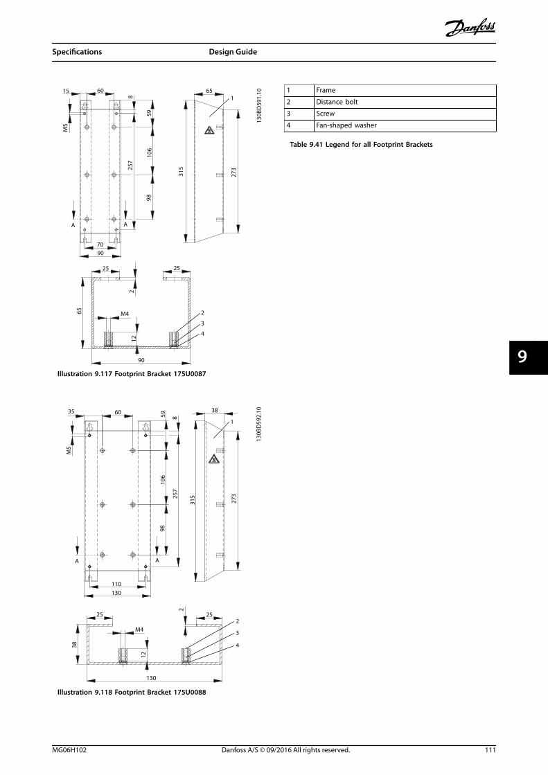
15 60 65
M5
8
25
M4
212
25
273
31525
7
106
9859
65
7090
90
A
1
2
3
4
A
130B
D59
1.10
Illustration 9.117 Footprint Bracket 175U0087
35 60 38
M5
8
25
M4
2
12
25
273
31525
7
106
9859
38
110130
130
A A
1
2
3
4
130B
D59
2.10
Illustration 9.118 Footprint Bracket 175U0088
1 Frame
2 Distance bolt
3 Screw
4 Fan-shaped washer
Table 9.41 Legend for all Footprint Brackets
Specifications Design Guide
MG06H102 Danfoss A/S © 09/2016 All rights reserved. 111
9 9
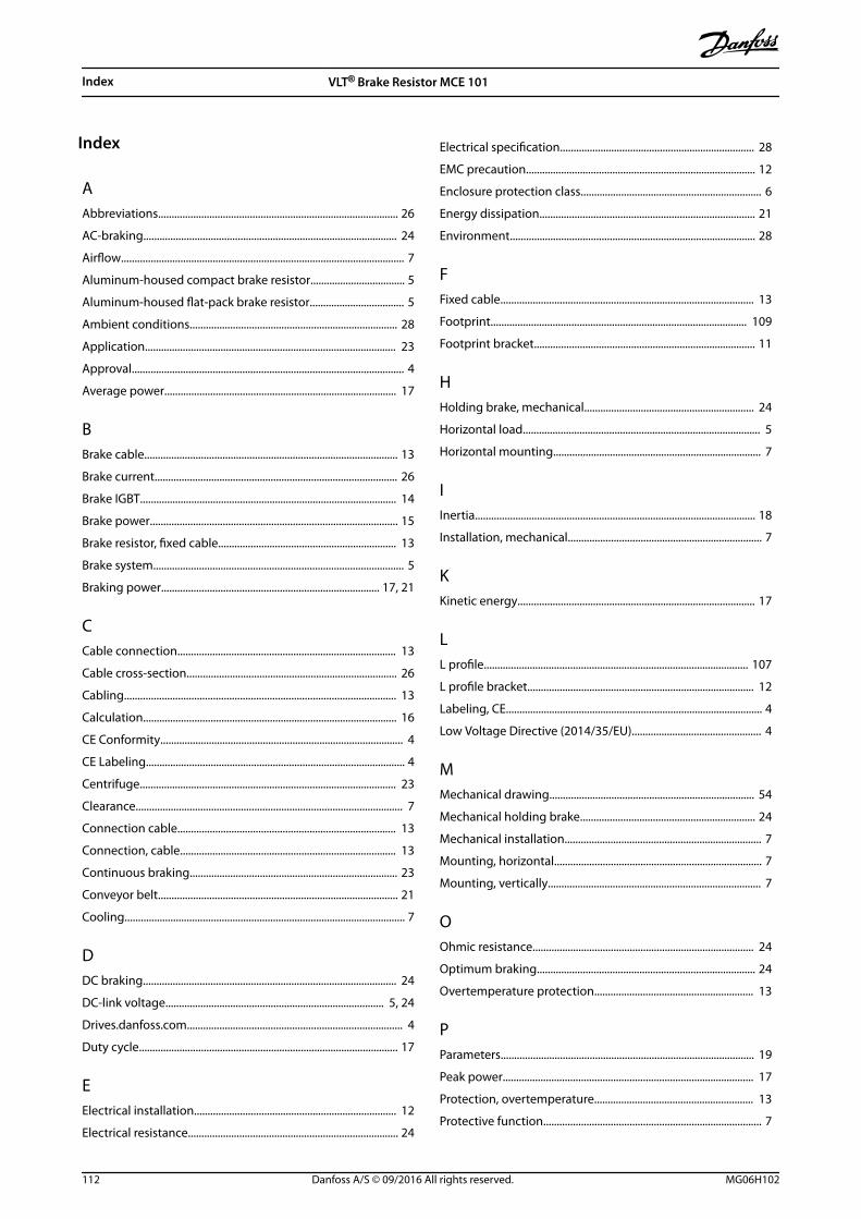
Index
AAbbreviations......................................................................................... 26
AC-braking.............................................................................................. 24
Airflow......................................................................................................... 7
Aluminum-housed compact brake resistor................................... 5
Aluminum-housed flat-pack brake resistor................................... 5
Ambient conditions............................................................................. 28
Application............................................................................................. 23
Approval..................................................................................................... 4
Average power...................................................................................... 17
BBrake cable.............................................................................................. 13
Brake current.......................................................................................... 26
Brake IGBT............................................................................................... 14
Brake power............................................................................................ 15
Brake resistor, fixed cable.................................................................. 13
Brake system............................................................................................. 5
Braking power................................................................................. 17, 21
CCable connection................................................................................. 13
Cable cross-section.............................................................................. 26
Cabling..................................................................................................... 13
Calculation.............................................................................................. 16
CE Conformity.......................................................................................... 4
CE Labeling................................................................................................ 4
Centrifuge............................................................................................... 23
Clearance................................................................................................... 7
Connection cable................................................................................. 13
Connection, cable................................................................................ 13
Continuous braking............................................................................. 23
Conveyor belt......................................................................................... 21
Cooling........................................................................................................ 7
DDC braking.............................................................................................. 24
DC-link voltage................................................................................. 5, 24
Drives.danfoss.com................................................................................ 4
Duty cycle................................................................................................ 17
EElectrical installation........................................................................... 12
Electrical resistance.............................................................................. 24
Electrical specification........................................................................ 28
EMC precaution..................................................................................... 12
Enclosure protection class................................................................... 6
Energy dissipation................................................................................ 21
Environment........................................................................................... 28
FFixed cable.............................................................................................. 13
Footprint............................................................................................... 109
Footprint bracket.................................................................................. 11
HHolding brake, mechanical............................................................... 24
Horizontal load........................................................................................ 5
Horizontal mounting............................................................................. 7
IInertia........................................................................................................ 18
Installation, mechanical........................................................................ 7
KKinetic energy........................................................................................ 17
LL profile.................................................................................................. 107
L profile bracket.................................................................................... 12
Labeling, CE............................................................................................... 4
Low Voltage Directive (2014/35/EU)................................................ 4
MMechanical drawing............................................................................ 54
Mechanical holding brake................................................................. 24
Mechanical installation......................................................................... 7
Mounting, horizontal............................................................................. 7
Mounting, vertically............................................................................... 7
OOhmic resistance.................................................................................. 24
Optimum braking................................................................................. 24
Overtemperature protection........................................................... 13
PParameters.............................................................................................. 19
Peak power............................................................................................. 17
Protection, overtemperature........................................................... 13
Protective function................................................................................. 7
Index VLT® Brake Resistor MCE 101
112 Danfoss A/S © 09/2016 All rights reserved. MG06H102

RResistance, electrical........................................................................... 24
Resistance, ohmic................................................................................. 24
Resistor time cycle.................................................................................. 5
SSafety precaution.................................................................................... 4
Selection flow chart............................................................................. 25
Selection guide..................................................................................... 25
Steel grid brake resistor........................................................................ 5
Surface temperature.............................................................................. 4
TTemperature switch............................................................................. 13
Thermo relay.......................................................................................... 14
Twisted cable......................................................................................... 13
VVertical load.............................................................................................. 5
Vertically mounting................................................................................ 7
Index Design Guide
MG06H102 Danfoss A/S © 09/2016 All rights reserved. 113

Danfoss can accept no responsibility for possible errors in catalogues, brochures and other printed material. Danfoss reserves the right to alter its products without notice. This also applies toproducts already on order provided that such alterations can be made without subsequential changes being necessary in specifications already agreed. All trademarks in this material are propertyof the respective companies. Danfoss and the Danfoss logotype are trademarks of Danfoss A/S. All rights reserved.
Danfoss A/SUlsnaes 1DK-6300 Graastenvlt-drives.danfoss.com
*MG06H102*130R0716 MG06H102 09/2016