Embed Size (px)
Citation preview

PENRITH CITY COUNCIL
DESIGN GUIDELINES FOR
ENGINEERING WORKS FOR
SUBDIVISIONS AND DEVELOPMENTS
Adopted by Council 21 April, 1997
In force from 20 May 1997
as amended 20 November 2013

i
Penrith City Council
DESIGN GUIDELINES FOR ENGINEERING WORKS FOR
SUBDIVISIONS AND DEVELOPMENTS
UPDATES REGISTRATION
If you would like to register for updates of this specification, please email the following details to Council’s
Development Engineering team at:
Name:
Organisation:
Position:
Email:
Telephone:

ii
Important Note
Please be advised that certain sub-sections of this document have been struck out to ensure consistency
with Penrith City Council’s Engineering Design Guidelines and Construction Specification for Civil Works. The information in the sub-sections no longer displayed in this document can still be found in
the Engineering Construction Specification for Civil Works.
iv
Table of Contents
Important Note ................................................................................................................................... ii
Table of Contents .............................................................................................................................. iv
SECTION 1 – GENERAL REQUIREMENTS ................................................................................ 1
1.1 INTRODUCTION............................................................................................................ 1
1.2 GENERAL ....................................................................................................................... 1
1.3 SUBMISSION OF ENGINEERING DRAWINGS ......................................................... 2
1.3.1 Engineering Drawings ........................................................................................................ 2
1.3.2 Persons Qualified ............................................................................................................... 3
1.3.3 Construction Standard ........................................................................................................ 4
1.3.4 Approval of Engineering Drawings ..................................................................................... 4
1.3.5 Plan Checking and Inspection Fees ..................................................................................... 4
1.3.6 Damage and Safety Bond.................................................................................................... 4
1.3.7 Performance Bonds ............................................................................................................ 5
1.4 INSPECTION OF WORKS............................................................................................. 5
1.5 WORKS-AS-EXECUTED (W.A.E) DRAWINGS .......................................................... 6
1.6 COMPLETION OF WORKS .......................................................................................... 8
1.6.1 Completion of Works and Final Inspection ......................................................................... 8
1.6.2 Maintenance of Works ........................................................................................................ 8
1.7 SURVEY REQUIREMENTS .......................................................................................... 9
1.7.1 Datum ................................................................................................................................ 9
1.7.2 Survey Control Marks ........................................................................................................ 9
1.7.3 Lot Boundaries ................................................................................................................... 9
1.8 EROSION AND SEDIMENT CONTROL ...................................................................... 9
1.8.1 Plans ................................................................................................................................. 9
1.8.2 General Requirements ...................................................................................................... 11
1.8.3 Construction Works .......................................................................................................... 12
1.8.4 Maintenance ..................................................................................................................... 12
1.8.5 Dust Control ..................................................................................................................... 13
1.9 MISCELLANEOUS....................................................................................................... 13
1.9.1 Tree Preservation.............................................................................................................. 13
1.9.2 Adjoining Owners Consent ............................................................................................... 13
1.9.3 Lot Filling/Grading ........................................................................................................... 13
1.9.4 Public Liability Insurance ................................................................................................. 14
1.9.5 Compliance with Acts ...................................................................................................... 14
1.9.6 Public Utility Services ...................................................................................................... 14
1.9.7 Street Lighting.................................................................................................................. 15
SECTION 2 – ROADS.................................................................................................................... 16
2.1 INTRODUCTION.......................................................................................................... 16
2.2 URBAN ROADS ............................................................................................................ 16
2.2.1 Plans ............................................................................................................................... 16
v
2.2.2 Longitudinal Sections ....................................................................................................... 17
2.2.3 Cross-Sections .................................................................................................................. 17
2.2.4 Kerb and Gutter ................................................................................................................ 18
2.2.5 Kerb Returns .................................................................................................................... 18
2.2.6 Traffic Control Devices .................................................................................................... 18
2.2.7 Local Area Traffic Management ....................................................................................... 18
2.2.8 Standard Road Widths ...................................................................................................... 19
2.2.9 Staged Road Construction ................................................................................................. 19
2.2.10 Pavement Design ............................................................................................................ 19
2.2.11 Classified Roads ............................................................................................................. 21
2.2.12 Road Surfacing ............................................................................................................... 21
2.2.13 Geometric Standards ....................................................................................................... 22
2.2.14 Vertical Alignment ......................................................................................................... 22
2.2.15 Vertical Curves ............................................................................................................... 23
2.2.16 Pavement Crossfalls ....................................................................................................... 23
2.2.17 Offset Crown .................................................................................................................. 23
2.2.18 Roundabouts................................................................................................................... 23
2.2.19 Footpath Crossfalls ......................................................................................................... 24
2.2.20 Concrete Path Paving ...................................................................................................... 24
2.2.21 Batters ............................................................................................................................ 24
2.2.22 Cul-de-Sacs .................................................................................................................... 24
2.2.23 Vehicular Access ............................................................................................................ 25
2.2.24 Street Name Signs .......................................................................................................... 25
2.2.25 Half Width Construction ................................................................................................. 25
2.2.26 Intersections ................................................................................................................... 25
2.2.27 Road Crossings ............................................................................................................... 26
2.2.28 Signposting and Pavement Markings ............................................................................... 26
2.3 RURAL/RURAL RESIDENTIAL ROADS................................................................... 26
2.3.1 Plan ............................................................................................................................... 26
2.3.2 Rural Road Widths ........................................................................................................... 26
2.3.3 Road Surfacing ................................................................................................................. 27
2.3.4 Longitudinal Section ........................................................................................................ 27
2.3.5 Cross-sections .................................................................................................................. 27
2.3.6 Pavement Design............................................................................................................. 28
2.3.7 Geometric Standards ........................................................................................................ 28
2.3.8 Sight Distance .................................................................................................................. 28
2.3.9 Vertical Alignment ........................................................................................................... 28
2.3.10 Pavement Crossfalls ....................................................................................................... 28
2.3.11 Clearing and Grubbing.................................................................................................... 28
2.3.12 Vehicular Access ............................................................................................................ 29
2.3.13 Guide Posts and Protection Fencing ................................................................................ 29
2.3.14 Intersections ................................................................................................................... 29
vi
2.3.15 Steep Grades .................................................................................................................. 29
2.3.16 Signposting and Pavement Markings ............................................................................... 30
SECTION 3 – MAJOR/MINOR SYSTEM DRAINAGE .............................................................. 31
3.1 INTRODUCTION.......................................................................................................... 31
3.2 DESIGN PROCEDURE ................................................................................................ 31
3.2.1 Persons Qualified ............................................................................................................. 32
3.3 DESIGN RECURRENCE INTERVALS....................................................................... 32
3.3.1 Minor System Drainage .................................................................................................... 32
3.3.2 Major System Drainage .................................................................................................... 32
3.4 PRELIMINARY LAYOUT OF PROPOSED MAJOR/MINOR SYSTEM DRAINAGE
33
3.5 CALCULATION OF MINOR SYSTEM FLOW .......................................................... 33
3.5.1 Design Rainfall Intensities ................................................................................................ 33
3.5.2 Times of Concentration .................................................................................................... 33
3.5.3 Runoff Coefficients .......................................................................................................... 34
3.5.4 Sub-Area Discharge.......................................................................................................... 35
3.5.5 Partial Area Flows ............................................................................................................ 36
3.6 ASSESSMENT OF MAJOR SYSTEM FLOWS........................................................... 36
3.7 PIT INLET DESIGN ..................................................................................................... 37
3.7.1 Pit Location ...................................................................................................................... 37
3.7.2 Inlet Design ...................................................................................................................... 37
3.8 DRAINAGE PIT DESIGN ............................................................................................ 38
3.8.1 General ............................................................................................................................ 38
3.8.2 Kerb Inlet Pits .................................................................................................................. 38
3.8.3 Junction Pits ..................................................................................................................... 39
3.8.4 Surface Inlet and Surcharge Pits........................................................................................ 39
3.9 PIPELINE DESIGN ...................................................................................................... 39
3.9.1 General Requirements ...................................................................................................... 39
3.9.2 Headwalls ........................................................................................................................ 39
3.9.3 Sub-Soil Drainage ............................................................................................................ 40
3.10 HYDRAULIC DESIGN ................................................................................................. 40
3.10.1 Pipe Friction Coefficients ............................................................................................... 40
3.10.2 Tailwater Levels ............................................................................................................. 40
3.10.3 Inlet Efficiency ............................................................................................................... 41
3.10.4 Pit Loss Factors .............................................................................................................. 41
3.11 DRAINAGE EASEMENTS ........................................................................................... 41
3.12 INTERALLOTMENT DRAINAGE SYSTEM ............................................................. 42
3.13 DESIGN PRESENTATION .......................................................................................... 43
Page 1 of 82
SECTION 1 – GENERAL REQUIREMENTS
1.1 INTRODUCTION
This section of the Engineering Guidelines for Subdivisions and Developments has been compiled to outline Council’s general procedures and practices in respect of the Engineering requirements for the subdivision and development of land within the City of Penrith. The following guidelines have been prepared in order to facilitate the efficient processing of Engineering Drawing submissions, construction approvals and linen plan releases for subdivisions and developments. Applicants should be aware that each development is required to be treated on its merits and that approval is dependent of the overall impact of the development on the area and not solely in compliance with minimum engineering standards. Council welcomes the submission of innovative design solutions and staffs are available for initial consultation to discuss and assess the prospects for approval. All Applicants are advised to ensure that all conditions of the Development Consent are addressed within the detailed Engineering Drawings. Any amendments to the development consent agreed to verbally by Council officers are to be confirmed in writing prior to the submission of the Engineering Drawings. All references to “Council’s Engineer” should be interpreted as a person acceptable to Council’s Development Engineering Services Manager or his nominated representative. All references to an “Engineer” should be interpreted as a person acceptable for Corporate Membership of the Institution of Engineers, Australia. All reference to a “Registered Surveyor” should be interpreted as referring to Penrith City Council’s Design Guidelines for Engineering Works for Subdivision and Developments.
1.2 GENERAL
When approval of a subdivision or other development includes conditions of construction which are embodied in the approved Engineering Drawings, the onus is on the Applicant to whom the approval is given to complete, or to cause the completion of, the works in accordance with approved Engineering Drawings and all relevant specifications.
Page 2 of 82
Before the Applicant commences the civil engineering works, Engineering Drawing(s) are to be submitted to and approved by Council’s Engineer. After obtaining approved construction drawings and specifications from Council and any consent required in writing from Statutory Authorities, and adjoining property owners if applicable, the Applicant may construct the roads, drainage and all other improvements comprising the works. It shall be noted clearly by all parties that the contractor is responsible to the Applicant and not the Council. The Applicant shall nominate to Council, the person or firm, with whom correspondence relating to the technical aspects of the development should be exchanged. Council’s Engineer does not carry out the functions of “Superintendent” as defined in the General Conditions of Contract – AS 2124, 1992. The Applicant is required to appoint a consultant to carry out this function and is to notify the Council of the Superintendent’s name, address and telephone number. Council will hold the Applicant, to whom the development approval was issued, solely responsible for constructing the required engineering works to Council’s satisfaction and maintaining them during any specified period. The Applicant shall nominate to Council’s Engineer, for approval prior to commencement of construction, the name, address and telephone number of the contractor/s who is/are to carry out the work at least seven (7) days prior to the proposed date of commencement of any construction. Details of experience and technical expertise in similar works and the financial capabilities of the contractor/s to carry out the works are also required by Council’s Engineer. The Applicant is advised that only those contractors, who have been prequalified by Council’s Engineer, are permitted to do works on existing public roads, for which Council is the Roads Authority, under the provisions of the Roads Act 1993.
1.3 SUBMISSION OF ENGINEERING DRAWINGS
1.3.1 Engineering Drawings
The following requirements apply in the preparation of Engineering Drawings for developments and subdivisions, including all associated work:- Engineering drawings are to be submitted in triplicate, with a covering letter, by the Applicant, and are to be accompanied by a completed copy of
Page 3 of 82
the Engineering Drawing Checklist (Appendix 1) and the Safety Audit (Appendix 2). It is suggested that one (1) A1 size set be forwarded initially for examination by Council and the additional two (2) sets forwarded upon approval. A CD/DVD with the engineering drawings and supporting documents is also to be provided for all lodgements Two (2) sets of approved Engineering Drawings will be returned to the Applicant once all engineering fees have been paid and any bonds lodged. A complete set of approved Engineering Drawings is to be on-site at all times. The following items shall be detailed in the drawings, and the layout of each should be on a separate sheet unless otherwise approved by Council’s Engineer.
1. A Cover Sheet with a Locality Plan and List of Drawings 2. Detailed Plan including road names 3. Road longsections and cross-sections 4. Drainage calculations, catchment plan and longsections 5. Landscaping Plan – if applicable 6. Erosion and Sediment Control Plan 7. Traffic Management Plan – if applicable
The detailed plan must include the following information:
1. North Point 2. Lot boundaries and numbers 3. Existing and proposed contours 4. Existing natural features including trees, dams, mounds, creeks,
etc. All trees to be removed as part of the engineering works are to be clearly identified.
5. Existing constructed features including fences, kerb and gutter, pipes, pits, road pavements, etc
6. Existing services 7. Extent of proposed works 8. “Bar” scales with a ratio scale shown adjacent thereto 9. List of symbols used
For uniformity of plan presentation and to facilitate filling and microfilming, all plan sizes, lettering, line work and symbols are to confirm to AS 1100 – Technical Drawing. All Engineering Drawings are to be signed by the Engineer engaged by the Applicant.
1.3.2 Persons Qualified
Council requires that engineering design drawings be prepared to Council’s standards by an Engineer, holding qualifications acceptable for
Page 4 of 82
Corporate Membership of the institution of Engineers, Australia, or other suitably qualified persons who can demonstrate to Council’s Engineer, proven experience in the preparation of plans and specifications for land development.
1.3.3 Construction Standard
These guidelines are not to be considered as a Code or a Specification, even though they do specify some basic requirements throughout. All works are to be carried out in accordance with Penrith City Council’s “Engineering Construction Specification for Civil Works (Working Draft)”, together with the appropriate standard specifications selected from other sources.
1.3.4 Approval of Engineering Drawings
The Civil Engineering Drawings will be checked by Council for compliance with these Guidelines. It is the responsibility of the person(s) or company submitting the documents, to ensure that the designs comply with the following:-
Council’s Subdivision Guidelines Relevant Australian Standards Relevant Local, State and Federal Government Legislation
Council’s Engineer’s approval is conditional on the above basis and does not relieve the application from rectifying any errors or omissions which become evident during construction.
1.3.5 Plan Checking and Inspection Fees
The Engineering Drawings will be released once the appropriate plan checking and inspection fees have been paid. The value of the fees will be assessed at the time of lodgement of the Engineering Drawings for Council approval. The rates for these charges will be furnished upon request.
1.3.6 Damage and Safety Bond
Prior to release of the approved Engineering Drawings, a Damage and Safety Bond is to be lodged with Council. The value of the Damage and Safety Bond will be assessed by Council. The Damage and Safety Bond covers the cost of repairing any damage which in the opinion of Council’s Engineer, is caused by the Applicant, his servants, contractors and the like to any Council property including roads
Page 5 of 82
during any phase of the construction works and/or providing any emergency traffic control measures deemed necessary. At the completion of the engineering works, the Applicant may request the transfer of the Damage and Safety Bond to be included as part of the Maintenance Bond.
1.3.7 Performance Bonds
Where engineering works are required in conjunction with a development application, a performance bond equal to the estimated cost of the works is to be lodged with Council prior to the release of the approved Engineering Drawings. The performance bond will be refunded once the works have been completed to the satisfaction of Council’s Engineer and, the maintenance bond, and any bonds for outstanding works have been lodged.
1.4 INSPECTION OF WORKS
The whole of the road, kerb and gutter, and drainage construction works,
which the applicant is required to carry out in respect of a development will be
inspected by Council’s staff. Inspections will be as detailed in Section 2.2.1 of
Penrith City Council’s “Engineering Construction Specification for Civil
Works (Working Draft)”. A Certificate of Inspection will be issued following
each inspection by Council’s Engineer.
The whole of the works are to be carried out to the entire satisfaction of
Council’s Engineer. The application shall at all times give uninterrupted
access and afford every facility for the examination of any works and materials
as requested by Council’s Engineer.
The applicant shall not obstruct, and will be held responsible for the safety of,
the public, traffic and utility services such as electricity, water, Telstra and the
like, and shall provide all watchmen, lights, barriers, signs and fences
necessary to prevent any accidents to public or private damage or loss.
The applicant shall provide, erect and maintain all necessary temporary roads,
bridges, footways, drains, supports and protection in order to ensure the above.
In the event of any of the abovementioned services being damaged or
interrupted, the applicant shall immediately notify the responsible Authority
and take all necessary steps to provide for the safety of the public and to have
the damage repaired as quickly as possible. The cost of all repairs is to be
resolved between the applicant and the relevant Authority.
Signs, barricades, barriers, warning lights, etc shall be placed where works are
in progress, and in accordance with AS 1742 – “Manual of Uniform Traffic
Control Devices.
Page 6 of 82
1.5 WORKS-AS-EXECUTED (W.A.E) DRAWINGS
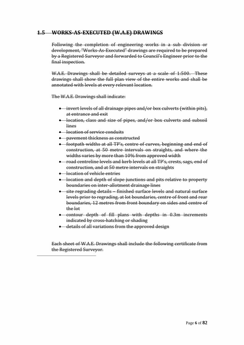
Following the completion of engineering works in a sub division or development, “Works-As-Executed” drawings are required to be prepared by a Registered Surveyor and forwarded to Council’s Engineer prior to the final inspection. W.A.E. Drawings shall be detailed surveys at a scale of 1:500. These drawings shall show the full plan view of the entire works and shall be annotated with levels at every relevant location. The W.A.E. Drawings shall indicate:
invert levels of all drainage pipes and/or box culverts (within pits), at entrance and exit
location, class and size of pipes, and/or box culverts and subsoil lines
location of service conduits pavement thickness as constructed footpath widths at all TP’s, centre of curves, beginning and end of
construction, at 50 metre intervals on straights, and where the widths varies by more than 10% from approved width
road centreline levels and kerb levels at all TP’s, crests, sags, end of construction, and at 50 metre intervals on straights
location of vehicle entries location and depth of slope junctions and pits relative to property
boundaries on inter-allotment drainage lines site regrading details – finished surface levels and natural surface
levels prior to regrading, at lot boundaries, centre of front and rear boundaries, 12 metres from front boundary on sides and centre of the lot
contour depth of fill plans with depths in 0.3m increments indicated by cross-hatching or shading
details of all variations from the approved design
Each sheet of W.A.E. Drawings shall include the following certificate from the Registered Surveyor.
Page 7 of 82
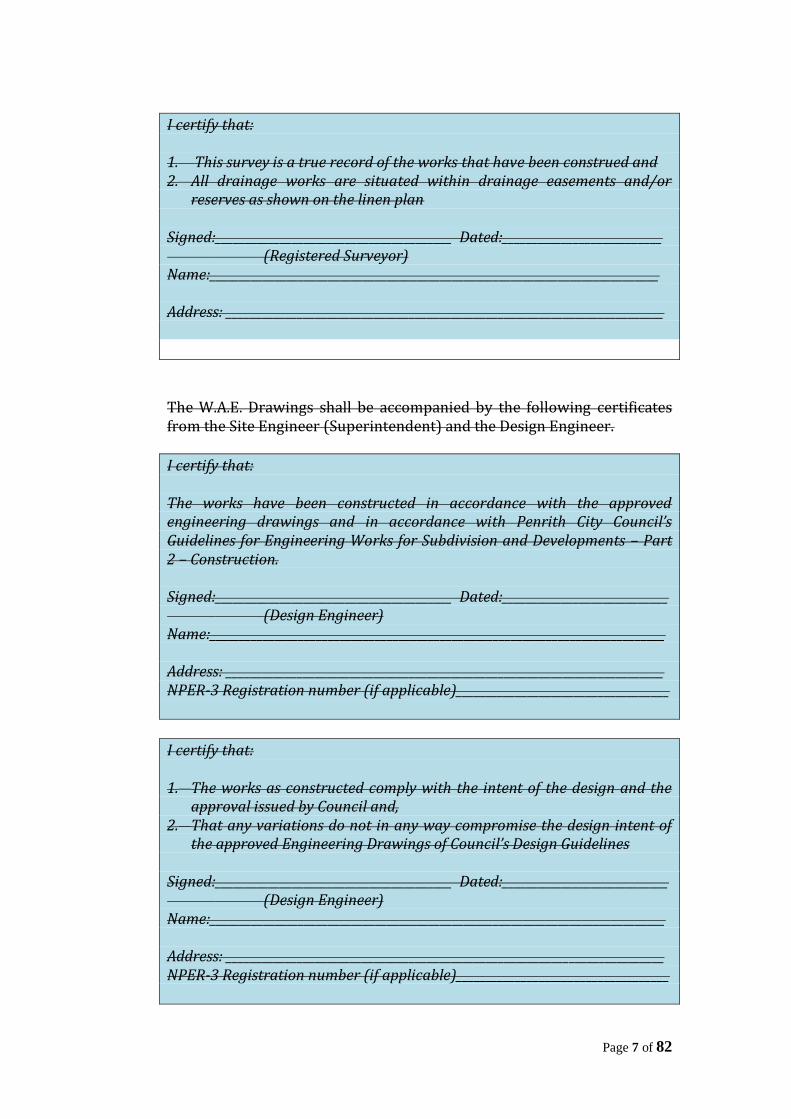
I certify that: 1. This survey is a true record of the works that have been construed and 2. All drainage works are situated within drainage easements and/or
reserves as shown on the linen plan Signed:________________________________________ Dated:___________________________ (Registered Surveyor) Name:____________________________________________________________________________ Address: __________________________________________________________________________
The W.A.E. Drawings shall be accompanied by the following certificates from the Site Engineer (Superintendent) and the Design Engineer.
I certify that: The works have been constructed in accordance with the approved engineering drawings and in accordance with Penrith City Council’s Guidelines for Engineering Works for Subdivision and Developments – Part 2 – Construction. Signed:________________________________________ Dated:____________________________ (Design Engineer) Name:_____________________________________________________________________________ Address: __________________________________________________________________________ NPER-3 Registration number (if applicable)____________________________________
I certify that: 1. The works as constructed comply with the intent of the design and the
approval issued by Council and, 2. That any variations do not in any way compromise the design intent of
the approved Engineering Drawings of Council’s Design Guidelines Signed:________________________________________ Dated:____________________________ (Design Engineer) Name:_____________________________________________________________________________ Address: __________________________________________________________________________ NPER-3 Registration number (if applicable)____________________________________
Page 8 of 82
Where considered necessary by Council’s Engineer, the Design Engineer shall supply any necessary supporting calculations. Appendix 3 contains a road inventory from which is to be completed and submitted with the W.A.E. Drawings to assist Council in maintaining its asset register.
1.6 COMPLETION OF WORKS
1.6.1 Completion of Works and Final Inspection
When the Applicant (or Superintendent) is of the opinion that the works have been completed, the Applicant shall submit the works-as-executed drawings and make arrangements with Council’s Engineer for a Preliminary Final Inspection to be undertaken. The Applicant, Superintended or contractor shall be present for the Preliminary Final Inspection and shall assist Council’s Engineer in the checking of levels, opening manholes etc., as required. All Street Name signs and advisory/warning signs are to be erected prior to the Preliminary Final Inspection by Council. A Certificate of Completion will be issued if the works have been completed satisfactory and there are no major errors, omissions or defects. Council’s Engineer may allow minor errors, omissions or defects to be bonded. The value of this bond will be determined by Council.
1.6.2 Maintenance of Works
The maintenance period shall be twelve (12) months or such longer period as determined by Council’s Engineer and shall commence on the date of release of the linen plan, in the case of subdivision works, or the date of issue of the Certificate of Completion in the case of development works. Subject to the maintenance bond being lodged with Council and bonds for outstanding works shall be released by Council following practical completion. The maintenance bond shall be an amount of five percent (5%) of the value of the total contract, with a minim amount of tow thousand five hundred dollars ($2500). This bond will be held by Council to cover any defects or omissions which may arise or become apparent in the maintenance period.
Page 9 of 82
At any time during the maintenance period, Council’s Engineer may direct the applicant to rectify any omission or defect in the work which exists at notification of completion or becomes apparent prior to the expiration of the Maintenance period. If defects or omissions are not rectified to the satisfaction of Council’s Engineer, Council shall be at liberty to rectify the same and apply the maintenance bond for payment of the cost thereof and may recover any additional costs from the applicant subject to Section 340 of the Local Government Act 1919. The nature of some defects may necessitate Council’s immediate action to repair. The maintenance bond will be used for the costs unless the applicant elects to pay Council separately.
1.7 SURVEY REQUIREMENTS
1.7.1 Datum
All survey shall be undertaken on Australian Height Datum.
1.7.2 Survey Control Marks
Where the works involve the construction of new roads, the plans of survey are to show connection to at least two (2) survey control permanent marks where such exist in the vicinity of the subdivision or where practicable. In the case where it is intended to open a new road at least two (2) control marks per sheet of the subdivision plan are to be established in the road by the Surveyor and connected to the nearest allotment corner. The location and level of all permanent survey marks established as part of the works are to be clearly shown on the work-as-executed drawings. The survey control marks shall be in accordance with the “Survey Practice Regulations, 1990”.
1.7.3 Lot Boundaries
Lot boundaries shall be established to the standard required by Surveyors (Practice) Regulation 1996, prior to the final inspection of works.
1.8 EROSION AND SEDIMENT CONTROL
1.8.1 Plans
The Applicant shall prepare an Erosion and Sediment Control Plan for approval by Council’s Engineer prior to commencement of construction in accordance with either of the following documents:
Page 10 of 82
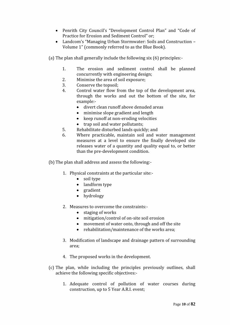
Penrith City Council’s “Development Control Plan” and “Code of Practice for Erosion and Sediment Control” or;
Landcom’s “Managing Urban Stormwater: Soils and Construction – Volume 1” (commonly referred to as the Blue Book).
(a) The plan shall generally include the following six (6) principles:-
1. The erosion and sediment control shall be planned concurrently with engineering design;
2. Minimise the area of soil exposure; 3. Conserve the topsoil; 4. Control water flow from the top of the development area,
through the works and out the bottom of the site, for example:- divert clean runoff above denuded areas minimise slope gradient and length keep runoff at non-eroding velocities trap soil and water pollutants;
5. Rehabilitate disturbed lands quickly; and 6. Where practicable, maintain soil and water management
measures at a level to ensure the finally developed site releases water of a quantity and quality equal to, or better than the pre-development condition.
(b) The plan shall address and assess the following:-
1. Physical constraints at the particular site:- soil type landform type gradient hydrology
2. Measures to overcome the constraints:-
staging of works mitigation/control of on-site soil erosion movement of water onto, through and off the site rehabilitation/maintenance of the works area;
3. Modification of landscape and drainage pattern of surrounding
area;
4. The proposed works in the development. (c) The plan, while including the principles previously outlines, shall
achieve the following specific objectives:-
1. Adequate control of pollution of water courses during construction, up to 5 Year A.R.I. event;

Page 11 of 82
2. Stability of control devices/structures up to 10 Year A.R.I. or such higher A.R.I. as deemed necessary by Council’s Engineer;
3. Zero annual impact by pollutants on receiving waters after completion of development.
1.8.2 General Requirements
Soil erosion and sediment control measures must be provided on site prior to the commencement of any site disturbance or development activity, in accordance with the approved erosion and sediment control plan. On all areas that will be disturbed, top soil is to be stripped and stockpiled. On completion of earthworks topsoil is to be replaced on all footpath reserves, batters and site regrading areas including drainage reserves and detention basins. Permanent vegetation shall be established as soon as practicable, after final levels are established. Perimeter control measures shall be placed prior to or in conjunction with the first phase of earthworks. The existing vegetation shall be preserved as much as possible. Unless otherwise directed by Council’s Engineer, the flowing principles shall be applied for the control of erosion and sedimentation:-
(a) Stabilisation of denuded areas shall commence within fifteen (15) days of the areas being disturbed;
(b) Stabilisation of the area over all stormwater drainage lines and sewer mains not within road reservations shall commence within fifteen (15) days of backfilling;
(c) All temporary earth diversion channels/banks and sediment basin embankments shall be seeded within fifteen (15) days of completion of the earthworks;
(d) Stabilisation of all cut and fill slopes shall be commenced within fifteen (15) days of completion of formation;
(e) All stabilisation measures shall be undertaken prior to issue of the Notification of Completion.
Footpath reserves, embankments, public reserves and open channels shall be grassed. To protect the grass cover during initial stages, a geotextile fabric (or any other approved by Council’s Engineer) should be used. The installation of the fabric shall be as per the manufacturer’s specification.
Page 12 of 82
Instead of grassing, above areas may be sown with seed and fertiliser using “Hydromulching” technique with the prior approval of Council’s Engineer. The use of “Hydromulching” will not be permitted in drainage channels. The seed variety/mixture for grassing shall be in accordance with Section 7 of Penrith City Council’s “Guidelines for Engineering Works for Subdivision and Developments – Part 2 – Construction”.
1.8.3 Construction Works
The construction works shall be carried out in accordance with the following procedure in relation to erosion and sediment control:-
1. Approval of “Soil and Water Management Plan (erosion and
sediment control)” by Council’s Engineer; 2. Clear minimum vegetation for site access; 3. Direct clean water away from the site; 4. Install erosion and sediment control devices; 5. Commence development works; 6. Undertake other erosion and sediment control practices as
required; 7. Ongoing review of the Erosion and Sediment Control Plan; 8. Removal of temporary devices after completion or works.
1.8.4 Maintenance
All sediment and erosion control devices shall be maintained in accordance with the approved erosion and sediment control plan and Council’s DCP and “Code of Practice for Erosion and Sediment Control”, throughout the Construction and Maintenance Period of until such time as the area has been stabilised and Council’s Engineer directs that the device be removed. The Contractor shall inspect the devices after each storm for structural damage or clogging by silt and other debris and make prompt repairs or replacement. All sediment deposited within ponded areas shall be periodically removed to a disposal area as directed by Council’s Engineer. Gravel or other filter materials shall be cleaned and restacked or replaced when directed by Council’s Engineer to maintain effective performance. In the case of the temporary construction exit, the contractor shall undertake weekly surface cleaning by drag broom or equivalent, to remove all build up of foreign material to the satisfaction of Council’s Engineer.

Page 13 of 82
To control bank growth and to maintain healthy ground cover in channels and on banks, mowing shall be undertaken as directed by Council’s Engineer. All costs associated with this Clause shall be borne by the applicant.
1.8.5 Dust Control
Appropriate dust control methods are to be employed to prevent the loss of soil via airborne dust. Prompt revegetation or mulching of disturbed area will reduce surface and airborne movement of sediment. Other methods of dust control include:
the retention of existing trees and shrubs to act as a windbreak the control of traffic movement over the construction site wetting the site surface is an emergency treatment which can be
repeated as necessary. Control of sediment laden runoff from over-watering must be closely monitored.
Council’s Engineer may stipulate that work cease until such time as any particular dust nuisance has been controlled to his satisfaction.
1.9 MISCELLANEOUS
1.9.1 Tree Preservation
The applicant is advised that NO trees are to be removed without Council permission. Engineering Drawings are to show all trees, and shall clearly define any trees proposed for removal. (Penrith City Council’s Tree Preservation Order defines a tree as “a perennial plant with a self-supporting stem which has a girth of 300mm or more, measured at a distance of 400mm above the ground and has a height in excess of 3.0 metres).
1.9.2 Adjoining Owners Consent
Where it is proposed to carry out work on or to discharge stormwater onto and adjoining property, the applicant is required to lodge the written consent of the property owner to the proposal. This consent is to be lodged prior to Council approval of the Engineering Drawings. At the completion of the engineering works, a written clearance is to be obtained from the adjoining property owner and lodged with Council prior to final inspection.
1.9.3 Lot Filling/Grading
Page 14 of 82
Any areas to be filled or regraded are to be clearly identified on the Engineering Drawings. Works are to be carried out in accordance with the requirements of Section 4.6 of Penrith City Council’s “Engineering Construction Guidelines for Civil Works” Where filling is proposed, provision is to be made to ensure that ponding of water on adjoining lots does not occur. Where fill is to extend onto adjoining properties, owners consent is required. The minimum lot grading shall be 1% and a minimum of 100mm of topsoil is to be placed over all fill areas.
1.9.4 Public Liability Insurance
Contractors engaged on Subdivision or Development Works must have a current Public Liability Insurance Policy to the value of at least $10 million. The policy shall specifically indemnify Council from all claims arising from the execution of the works. Prior to commencement of works, the applicant is to submit proof of all contractor’s public liability insurance.
1.9.5 Compliance with Acts It is the responsibility of the applicant and his contractor/s to ensure that all works are undertaken in a safe and efficient manner. In particular, the applicant and his contractor/s shall ensure compliance with the Occupational Health and Safety Act (1983) and any other relevant Acts, Ordinances and Regulations in New South Wales.
1.9.6 Public Utility Services
All services should generally run parallel to the road centreline and should cross the road centreline perpendicular to it unless otherwise approved by Council’s Engineer. Service conduits are to be provided at locations specified by the relevant authority and in accordance with their requirements. All service authorities are to have completed the installation of services prior to the final inspection of the works by Council. Should the installation of utility services require the opening of any public roads, reserves, etc, then a road opening permit is to be obtained from Council. Restoration of disturbed areas is to be completed to the satisfaction of Council’s Engineer prior to final inspection and release of the linen plan of subdivision.

Page 15 of 82
1.9.7 Street Lighting
The use of non-standard street lamps (ie: Prestigious Lamps) throughout a subdivision may result in additional street lights being required to provide the appropriate lighting level (AS 1158-1). Where it is intended to use lighting of this nature, the Applicant will be required to pay a contribution to Council based on the annual running costs, over a 20 year period, for the additional street lights. The value of this contribution will be determined by Council and is to be paid prior to release of the linen plan of subdivision.
Page 16 of 82
SECTION 2 – ROADS
2.1 INTRODUCTION
This section of the Engineering Guidelines for Subdivisions and Developments outlines Penrith City Council’s recommended practice for the design of urban and rural roads. It is in no way a comprehensive “Design Manual” and it is intended to be read in conjunction with and as a supplement to relevant Roads and Maritime Services(RMS) and AUSTROADS Publications. All references to “Council’s Engineer” should be interpreted as referring to Council’s Engineering Services Manager or his nominated representative. All references to an “Engineer” should be interpreted as a person acceptable for Corporate Membership of the Institution of Engineers, Australia. All references to “Engineering Guidelines” should be interpreted as referring to Penrith City Council’s “Design Guidelines for Engineering Works for Subdivisions and Developments”.
2.2 URBAN ROADS
2.2.1 Plans
The plans are to be drawn at a scale of 1:500 and shall include the following:-
(a) Lot boundaries and numbers; (b) Road centreline chainages, radii, tangent points and deflection
angles; (c) A benchmark within 100 metres of the development site; (d) Street names; (e) North Point; (f) Bar Scales; (g) Existing services and structures, including dwellings, dams, out
buildings and other significant landmarks; (h) Drainage details including pipe sizes and pit locations; (i) Proposed service crossings; (j) Road reserve and carriageway width; (k) All datum references shall be to Australian Height Datum; (l) A schedule of symbols; (m) Radii on kerb returns and kerb lines; (n) Vehicular Crossings; (o) Location of all significant trees; (p) Existing and proposed contours
Page 17 of 82
2.2.2 Longitudinal Sections
A longitudinal section of the centreline of the roads shall be supplied at scales of:- 1:500 horizontal 1:100 vertical The longitudinal section of the centreline of roads shall show chainages, reduced level of existing surface and of design level of road, design grades, length of vertical curves and, where appropriate stopping sight distance. Longitudinal levels should be taken at maximum 20 metre intervals and at all intermediate changes of grade. Kerb return profiles shall be detailed. Longitudinal sections and cross-sections shall be taken along existing intersecting roads for a sufficient distance (approx. 50 metres) to enable kerb returns, dish crossing and any necessary drainage to be designed.
2.2.3 Cross-Sections
Cross-sections shall be supplied at intervals not exceeding 30 metres for straights and 15 metres at curves, at scales of 1:100 natural. Cross-sections shall show chainage, reduced levels of existing surface and the design level of pavement, kerb and gutter and footpath. Cross-sections shall not be terminated at the property alignment but shall be levelled sufficiently beyond the road boundaries to enable batters of cutting and embankment to be shown. Cross-sections shall show how the new construction ties in with any existing road pavement. A typical cross-section is to be included for each road and shall generally show the following information:-
(a) Crossfall on road carriageway; (b) Crossfall on footway with a 0.5m berm inside the lots; (c) Concrete path paving 1.5m wide 0.9m from property boundaries
on roads where a need has been determined by Council; (d) A note that pavement thickness is to be designed in accordance
with Council’s specification by a N.A.T.A. registered geotechnical consultant.
Page 18 of 82
2.2.4 Kerb and Gutter
All streets are to be provided with an approved sealed pavement with kerb and gutter to adequately and safely provide both vehicular and pedestrian access to each allotment. Pram ramps are to be provided in all kerb returns. Where it is considered impractical to construct an isolated section of kerb and gutter and road pavement, Council will require the applicant to pay a contribution in lieu of construction, based on the estimated full cost of the works calculated by Council’s Engineer. Kerb and gutter types as down on the Department of Housing Drawing No. RM1 are to be provided as follows:-
(a) 150mm high integral kerb and gutter – distributor, collector and industrial and adjacent to public reserves, etc;
(b) Roll kerb and gutter – shareways, cul-de-sacs and access streets; (c) Mountable kerb adjacent to medians and traffic islands.
In general 150mm high integral kerb and gutter shall be provided on all roads, except for traffic control facilities, with any variation to be approved by Council’s Engineer.
2.2.5 Kerb Returns
Kerb profiles shall be shown for all kerb returns and cul-de-sac bulbs. A scale of 1:200 horizontally and 1:100 vertically is suggested.
2.2.6 Traffic Control Devices
The Applicant shall provide and install any necessary traffic control devices as required by the RMS. The consent of the Penrith Local Traffic Committee shall be obtained prior to the installation of any traffic control devices. Signs, barricades, barriers, warning lights, etc., shall be in accordance with AS.1742 – “Manual of Uniform Traffic Control Devices”.
2.2.7 Local Area Traffic Management
Local Area Traffic Management Devices may be required as a condition of Development Consent. Alternatively, applicants may elect to install these devices where appropriate. The use and installation of the devices shall be in accordance with Australian Standard 1742 (Part 13) – Local Area Traffic Management. All Traffic Management Devices are to be approved by the Local Traffic Committee.
Page 19 of 82
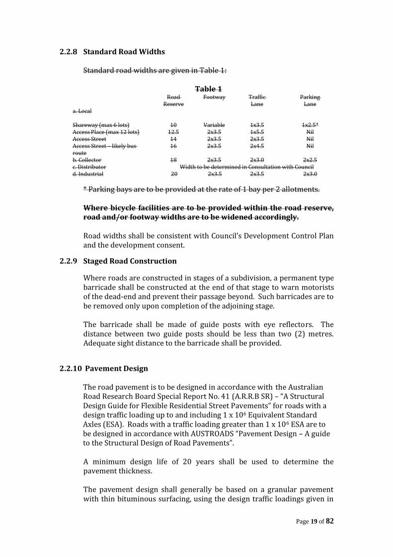
2.2.8 Standard Road Widths
Standard road widths are given in Table 1:
Table 1 Road
Reserve Footway Traffic
Lane Parking
Lane a. Local Shareway (max 6 lots) 10 Variable 1x3.5 1x2.5* Access Place (max 12 lots) 12.5 2x3.5 1x5.5 Nil Access Street 14 2x3.5 2x3.5 Nil Access Street – likely bus route
16 2x3.5 2x4.5 Nil
b. Collector 18 2x3.5 2x3.0 2x2.5 c. Distributor Width to be determined in Consultation with Council d. Industrial 20 2x3.5 2x3.5 2x3.0
* Parking bays are to be provided at the rate of 1 bay per 2 allotments. Where bicycle facilities are to be provided within the road reserve, road and/or footway widths are to be widened accordingly. Road widths shall be consistent with Council’s Development Control Plan and the development consent.
2.2.9 Staged Road Construction
Where roads are constructed in stages of a subdivision, a permanent type barricade shall be constructed at the end of that stage to warn motorists of the dead-end and prevent their passage beyond. Such barricades are to be removed only upon completion of the adjoining stage. The barricade shall be made of guide posts with eye reflectors. The distance between two guide posts should be less than two (2) metres. Adequate sight distance to the barricade shall be provided.
2.2.10 Pavement Design
The road pavement is to be designed in accordance with the Australian Road Research Board Special Report No. 41 (A.R.R.B SR) – “A Structural Design Guide for Flexible Residential Street Pavements” for roads with a design traffic loading up to and including 1 x 10⁶ Equivalent Standard Axles (ESA). Roads with a traffic loading greater than 1 x 10⁶ ESA are to be designed in accordance with AUSTROADS “Pavement Design – A guide to the Structural Design of Road Pavements”. A minimum design life of 20 years shall be used to determine the pavement thickness. The pavement design shall generally be based on a granular pavement with thin bituminous surfacing, using the design traffic loadings given in
Page 20 of 82
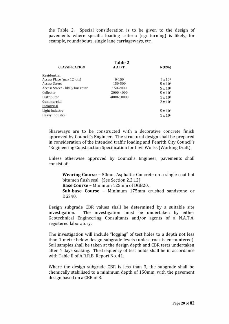
the Table 2. Special consideration is to be given to the design of pavements where specific loading criteria (eg: turning) is likely, for example, roundabouts, single lane carriageways, etc.
Table 2 CLASSIFICATION A.A.D.T. N(ESA)
Residential Access Place (max 12 lots) 0-150 5 x 10⁴ Access Street 150-500 5 x 10⁴
Access Street – likely bus route 150-2000 5 x 10⁵
Collector 2000-4000 5 x 10⁵
Distributor 4000-10000 1 x 10⁶
Commercial 2 x 10⁶
Industrial Light Industry 5 x 10⁶
Heavy Industry 1 x 10⁷
Shareways are to be constructed with a decorative concrete finish approved by Council’s Engineer. The structural design shall be prepared in consideration of the intended traffic loading and Penrith City Council’s “Engineering Construction Specification for Civil Works (Working Draft). Unless otherwise approved by Council’s Engineer, pavements shall consist of:
Wearing Course – 50mm Asphaltic Concrete on a single coat hot bitumen flush seal. (See Section 2.2.12) Base Course – Minimum 125mm of DGB20. Sub-base Course – Minimum 175mm crushed sandstone or DGS40.
Design subgrade CBR values shall be determined by a suitable site investigation. The investigation must be undertaken by either Geotechnical Engineering Consultants and/or agents of a N.A.T.A. registered laboratory. The investigation will include “logging” of test holes to a depth not less than 1 metre below design subgrade levels (unless rock is encountered). Soil samples shall be taken at the design depth and CBR tests undertaken after 4 days soaking. The frequency of test holds shall be in accordance with Table II of A.R.R.B. Report No. 41. Where the design subgrade CBR is less than 3, the subgrade shall be chemically stabilised to a minimum depth of 150mm, with the pavement design based on a CBR of 3.

Page 21 of 82
A copy of the site investigation report including test results shall be submitted with the pavement design and the Engineering Drawings. The pavement design is to include the following certificate from the Geotechnical Engineer:
I certify that: 1. This pavement design has been prepared in full recognition of the likely
existing subgrade conditions, the anticipated traffic loadings, the pavement materials to be used in the construction and the method of pavement construction.
2. The design has been undertaken in accordance with AUSTROADS Pavement Design 1992 or A.R.R.B. Report No. 41. (Delete whichever is not applicable).
3. The engineering drawings include the relevant sub-surface drainage requirements to achieve the pavement design, and
4. The design complies with the relevant Specifications of Penrith City Council.
Signed:_________________________________________ Date: ____________________________ (Geotechnical Engineer) Name: _____________________________________________________________________________ Address: ___________________________________________________________________________ NPER-3 Registration number (if applicable) ___________________________________
2.2.11 Classified Roads
All works on or adjacent to Classified Roads shall be approved by, and constructed to the requirements of the Roads and Maritime Services. The applicant is to contact the RMS for details of their Construction Standards and supervision requirements.
2.2.12 Road Surfacing
All new roads and widening of existing roads are to have a wearing surface consisting of 50mm of Asphaltic Concrete, placed in two layers, on a single coat hot bitumen flush seal. The placement of the first 25mm layer of AC10 shall not be undertaken until all services have been installed and permission obtained from Council’s Engineer. Works are to be completed prior to the final inspection by Council’s Engineer. Placement of the final 25mm layer of AC10 will generally be delayed for a period of twelve (12) months or until the majority (approx. 80%) of
Page 22 of 82
dwellings have been erected within the subdivision. For roads with traffic loadings up to 5 x 10⁵ ESA, the final 25mm layer of AC shall be “Residential” mix. A bond covering the cost of the placement of this layer, is to be lodged with Council prior to the release of the linen plan of subdivision. The value of this bond will be determined by Council.
2.2.13 Geometric Standards
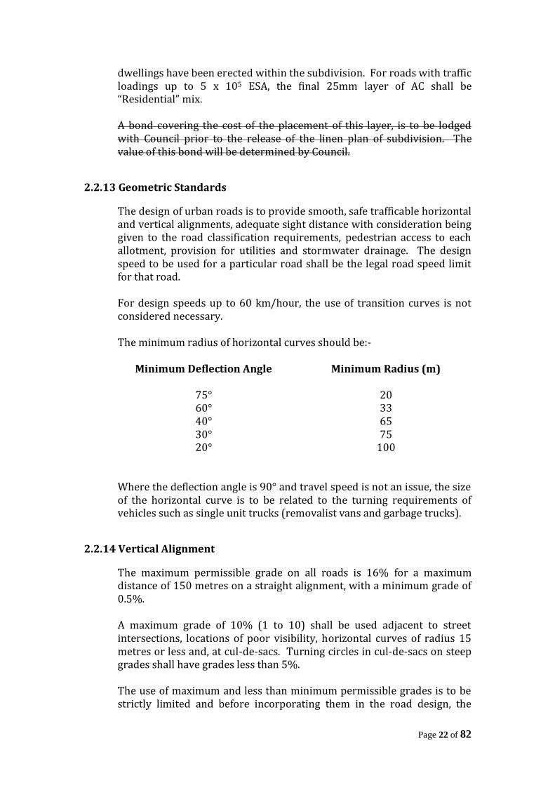
The design of urban roads is to provide smooth, safe trafficable horizontal and vertical alignments, adequate sight distance with consideration being given to the road classification requirements, pedestrian access to each allotment, provision for utilities and stormwater drainage. The design speed to be used for a particular road shall be the legal road speed limit for that road. For design speeds up to 60 km/hour, the use of transition curves is not considered necessary. The minimum radius of horizontal curves should be:-
Minimum Deflection Angle Minimum Radius (m)
75° 20 60° 33 40° 65 30° 75 20° 100
Where the deflection angle is 90° and travel speed is not an issue, the size of the horizontal curve is to be related to the turning requirements of vehicles such as single unit trucks (removalist vans and garbage trucks).
2.2.14 Vertical Alignment
The maximum permissible grade on all roads is 16% for a maximum distance of 150 metres on a straight alignment, with a minimum grade of 0.5%. A maximum grade of 10% (1 to 10) shall be used adjacent to street intersections, locations of poor visibility, horizontal curves of radius 15 metres or less and, at cul-de-sacs. Turning circles in cul-de-sacs on steep grades shall have grades less than 5%. The use of maximum and less than minimum permissible grades is to be strictly limited and before incorporating them in the road design, the

Page 23 of 82
Applicant shall seek a determination from Council’s Engineer as to the permissible length for such grades. Council’s drainage requirements on steep grades will involve special structures and extensive piping of easements. Since this may be relatively expensive, applicants may find it more economical to avoid the use of steep grades. Gutters are to have a minimum grade of 0.5% (1 in 200) and special consideration shall be given to the desirability of increasing such minimum grade where changes of direction or drainage concentration occur.
2.2.15 Vertical Curves
Vertical curves are to be provided at all changes of grade and where practical coincide with the horizontal curvature. The values given in AUSTROADS “Guide to the Geometric Design of Rural Roads – 1989”, are applicable to urban conditions in the relevant ranges.
2.2.16 Pavement Crossfalls
The normal crossfall on bituminous pavements shall be 3%. The maximum crossfall permitted will occur in super-elevated curves and road intersections and, any proposal to use crossfalls in excess of 6% shall be referred to Council’s Engineer for approval. Should design speeds so require, super-elevation of horizontal curves is to be based on the current AUSTROADS design policy for urban roads.
2.2.17 Offset Crown
In areas where it is uneconomical to have the crown on the centre of the road, due to the formation of the terrain, the crown may be shifted towards the high side of the road. Any shifting of the crown shall be such that it is not closer to the kerb line than 3.5 metres.
2.2.18 Roundabouts
The design of roundabouts shall be in accordance with AUSTROADS “Guide to Traffic Engineering Practice Part 6 – Roundabouts”. The central island radius shall be determined by Council’s Engineer and will relate to the type of intersection and traffic movements. The minimum radius of the central island shall be 4 metres.
Page 24 of 82
2.2.19 Footpath Crossfalls
In areas where the footpath reservation is to be totally paved from the top of the kerb to the adjacent boundary, the crossfall is to be 1 in 50 towards the kerb (2%). In areas where the footpath is unpaved or partially paved, crossfall from kerb to the adjacent boundaries is to be 1 in 25 towards the kerb (4%) with the concrete footpath having a crossfall of 1 in 50 (2%) towards the kerb.
2.2.20 Concrete Path Paving
Where concrete path paving is to be provided, its construction is to be bonded for a period of twelve (12) months or until the majority (minimum 80%) of dwellings have been constructed. Concrete path paving is to be constructed in accordance with Section 7.5 of Penrith City Council’s “Engineering Construction Specification for Civil Works (Working Draft)”. The applicant is to ensure that the proposed location of concrete path paving is clearly shown on all sales plans.
2.2.21 Batters
All roads shall be cleared full width and 0.5 metres inside the lot boundaries, or to a sufficient width to include cut and fill batters. Footpaths reserves shall be formed so as to extend 0.5 metres past the road alignment into the adjacent allotments to enable fences to be constructed at road level. Road batters shall lie wholly within the adjacent allotments commencing 0.5 metres beyond road boundaries. Such batters shall not be steeper that one (1) vertical to five (5) horizontal, except by special permission of Council’s Engineer and, in the case of fill embankments, the provision of appropriate easements for support.
2.2.22 Cul-de-Sacs
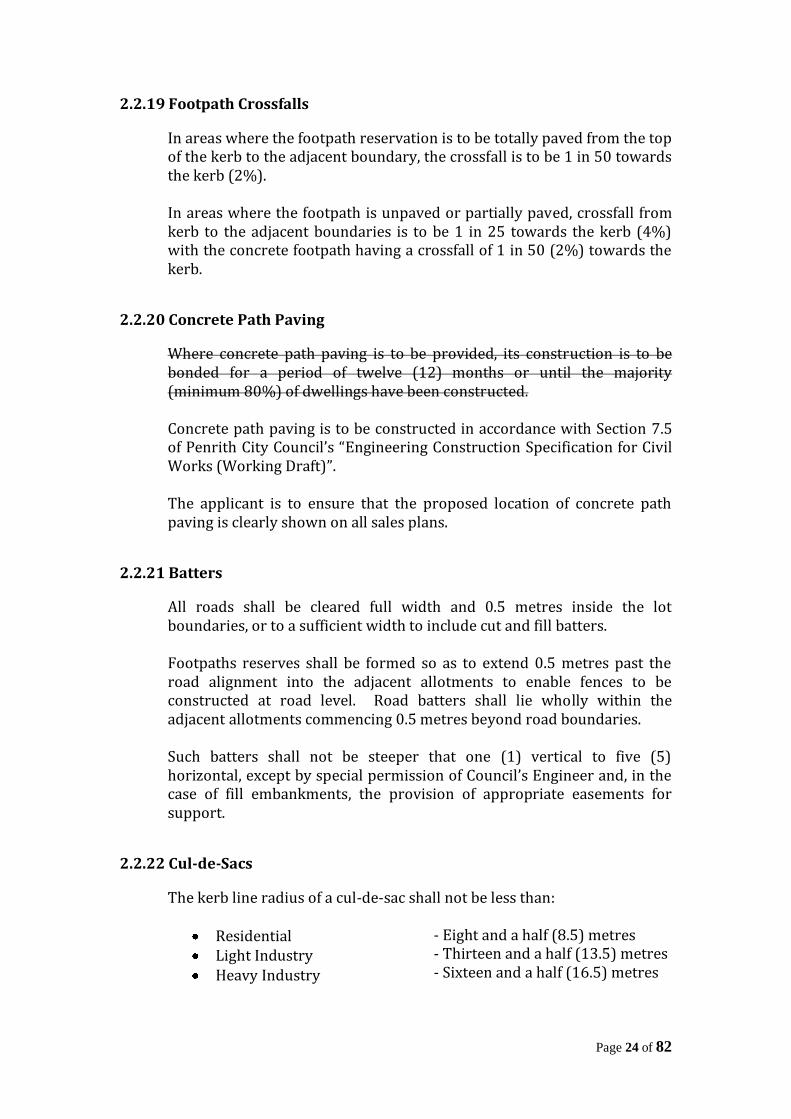
The kerb line radius of a cul-de-sac shall not be less than:
Residential Light Industry Heavy Industry
- Eight and a half (8.5) metres - Thirteen and a half (13.5) metres - Sixteen and a half (16.5) metres
Page 25 of 82
Down hill cul-de-sacs should generally be avoided. Where they are unavoidable however, then special provision shall be made to take drainage through easements or drainage reserves. Alternative treatments of cul-de-sacs, such a “T” and “Y” heads, may be considered in consultation with Council’s Engineer.
2.2.23 Vehicular Access
Roads shall be so located and designed that vehicular access can be readily obtained to every allotment of a development. Where the natural surface slopes steeply to or from the road, the access to each lot shall be given special consideration. Major drainage carried in roads must not be allowed to enter properties via the vehicular access.
2.2.24 Street Name Signs
Street name signs are to be manufactured in accordance with Council’s standard drawings SD1006/1 and SD1006/2 and shall be erected at all street intersections. The street name, house numbers and colour of sign are to be ascertained from Council and the sign location is to be shown on the Engineering Drawings. Street name signs are to be erected prior to final inspection by Council.
2.2.25 Half Width Construction Where proposed subdivisions or developments front an existing sealed road and the existing pavement is of adequate strength and the vertical alignment is satisfactory, the existing pavement may be retained. The remainder of the half width construction is to be carried out to the equivalent standard of full width construction. Should the existing pavement be unsatisfactory, either in terms of shape or condition, then the pavement construction is to extend to the road centreline. In all cases, the new wearing surface shall extend to the road centreline to avoid irregularities. Half width construction shall provide sufficient pavement width to allow safe two way vehicle movement.
2.2.26 Intersections
“T” junctions shall be adopted in preference to four way intersections. Where staggered “T” junctions are to be provided, the junctioning roads
Page 26 of 82
shall be spaced a minimum distance of 2 x stopping distance for the travel speed along the through-road (1.5 second reaction time). Roads shall junction at not less than 70°. Where intersections are in a configuration deemed likely to cause traffic problems, Council’s Engineer may require the construction of traffic islands, or such traffic facilities to provide traffic control and safety. Intersection design shall be based on AUSTROADS guidelines.
2.2.27 Road Crossings
All conduit trenches shall be at a grade of not less than one (1) percent and shall be clearly located on relevant drawings. Conduits under roads shall be laid prior to the construction of the initial pavement course and their location clearly marked on the kerb and gutter
2.2.28 Signposting and Pavement Markings
Signposting and pavement markings in accordance with Australian Standard AS 1742 – ‘Manual of Uniform Traffic Control Devices”, are to be provided where required.
2.3 RURAL/RURAL RESIDENTIAL ROADS
2.3.1 Plan
Plans shall be drawn at a scale of 1:500 or 1:1000 and show lot boundaries and numbers, road centreline chainages, radii and bearings, road names, locality sketch and a north point. The plan shall also show the location and reduced level of the bench marks used in the survey works, the location of vehicular entrances, existing and proposed drainage structures, trees, public utilities and any other information and improvements to make the plan complete. All datum references shall refer to Australian Height Datum adopted by the New South Wales Department of Lands.
2.3.2 Rural Road Widths
The road reserve width for rural roads shall generally be in accordance with Council’s Development Control Plan.
Page 27 of 82
Roads are to have a minimum 6 metre wide seal, widened as required, on a 6.6 metre pavement with 2 metre wide shoulders. Drains, a minimum 1.5 metres wide are to be provided in all cuttings.
2.3.3 Road Surfacing
The carriageway of Rural/Rural Residential roads shall be sealed to a minimum standard of two coat hot bitumen spray seal. The shoulders shall be sealed 0.5 metres wide with a 120mm wide edgeline for roads with A.A.D.T. greater than 1,000. The shoulder adjacent to a barrier centreline is to be widened to 3.0 metres.
2.3.4 Longitudinal Section
A longitudinal section of the centreline of the roads shall be supplied at scales of:- 1:500 or 1:1000 horizontal 1:100 vertical The longitudinal section of the centreline of roads shall show chainages, reduced level of existing surface and of design level of road, design grades, length of vertical curves, drainage information, extent or roadworks and stopping distance if appropriate. Longitudinal levels shall be taken at 30m intervals along straight alignments and horizontal curves exceeding R1000m, at 20m intervals for horizontal curves between R150m and R1000m and at 10m intervals for horizontal curves less than R150m and at all intermediate changes of grade. Longitudinal sections and cross – sections shall be taken along existing intersecting roads for a sufficient distance to enable design requirements to be satisfied.
2.3.5 Cross-sections
Cross-sections shall be supplied at 30m intervals along straight alignments and horizontal curves exceeding R100m and at 15m intervals for horizontal curves R1000 and less. Cross-sections shall be supplied at all culvert sites and at the S.S., T.S., T.P. and S.C. of each horizontal curve if applicable. The scale shall be 1:100 natural. Cross-sections shall not be terminated at the property alignment but shall be levelled sufficiently beyond the road boundaries to enable batters of cutting and embankment to be shown.
Page 28 of 82
Cross-sections shall show chainages, reduced level of existing surface and design surface on the road centreline, crossfalls, centreline offsets if applicable and lateral dimensions if pavement and formation widths vary. Batter slopes are to be indicated if they vary from those shown on the typical cross-section. A typical cross-section is to be included showing information necessary for construction purposes.
2.3.6 Pavement Design
Section 2.210 of this guideline shall be followed.
2.3.7 Geometric Standards
The Geometric design of rural roads is to be based on AUSTROADS guidelines. The design speed to be used for a particular road shall be the legal road speed limit for that road. Should conditions so require, the design speed may be increased of lowered to the satisfaction of Council’s Engineer.
2.3.8 Sight Distance
Adequate horizontal and vertical sight distance shall be provided for the design speed in accordance with AUSTROADS guidelines. Council will not permit vehicular access to properties where the stopping sight distance is not available.
2.3.9 Vertical Alignment
The maximum permissible grade on all roads is 16% for a maximum distance of 150 metres on straight alignment, with a minimum grade of 1.0%. A maximum grade of 10% (1 in 10) shall be used adjacent to street intersections, locations of poor visibility, horizontal curves of radius 15 metres or less and at cul-de-sacs. Turning circles in cul-de-sacs on steep grades shall have grades less that 5%.
2.3.10 Pavement Crossfalls
The normal crossfall on bituminous pavements shall be 3% and the minimum crossfall on unsealed shoulders shall be 4%. The maximum crossfall permitted will occur on super-elevation curves and road intersections and any proposal to use excessive crossfalls shall be referred to Council’s Engineer for approval.
2.3.11 Clearing and Grubbing
Page 29 of 82
All road reserves shall be cleared approximately 0.5 metres beyond the extent of roadworks. Preservation of trees will be considered by Council’s Engineer if they are found to be clear of traffic requirements and location of services.
2.3.12 Vehicular Access
Roads shall be located and designed so that vehicular access can be readily obtained at every lot of a subdivision. Where the natural surface slopes steeply to or from the road, the access to each lot shall be given special consideration. Major drainage carried in roads must not be allowed to enter properties via the vehicular access.
2.3.13 Guide Posts and Protection Fencing
Guide posts and protection fencing are to be provided in accordance with the appropriate RMS. (MR) Form, where required.
2.3.14 Intersections
“T” junctions shall be adopted in preference to four way intersections. Where staggered “T” junctions are to be provided, the junctioning roads shall be spaced a minimum distance of 2 x stopping distance for the travel speed along the through-road (1.5 second reaction time). Roads shall junction at not less than 70°. Where intersections are in a configuration deemed likely to cause traffic problems, Council’s Engineer may require the construction of traffic islands, or such traffic facilities to provide traffic control and safety. Intersection design shall be based on AUSTROADS. “Guide to Traffic Engineering Practice Part 5 – Intersections at Grade”.
2.3.15 Steep Grades
Where grades exceed 6%, a one coat bitumen seal is to be provided on the road shoulders. Where shoulders are sealed, edge line marking is to be provided. Where the grade of the table drain exceeds 6% or scouring is likely, a concrete lined drain, or kerb and gutter is to be provided. Where the terrain permits, batters in the region of 1 in 5 are desirable. Proposed batters of greater slope than 1 in 5 shall be referred to Council’s Engineer for direction.

Page 30 of 82
2.3.16 Signposting and Pavement Markings
Signposting and pavement markings in accordance with Australian Standard AS 1742 – “Manual of Uniform Traffic Control Devices”, are to be provided where required.
Page 31 of 82
SECTION 3 – MAJOR/MINOR SYSTEM DRAINAGE
3.1 INTRODUCTION
This document outlines Penrith City Council’s recommended practice for drainage design. It is in no way a comprehensive “Design Manual” and is intended to be read in conjunction with and as a supplement to the 1987 edition of “Australian Rainfall and Runoff” (referred to as “AR&R”). The Design Coefficients defined in the Tables and Figures within this Manual are applicable only to the City of Penrith. The “Major/Minor” concept is adopted for urban drainage design. The “Minor” system refers to the underground piped system, designed to an Average Recurrence Interval as determined in Section 3.3. The “Major” system refers to overland flow paths which are to be designed to convey major storm flows when the capacity of the minor system is exceeded. Although the parameters and techniques for Flow Estimation in urban catchments, as set out in these Guidelines, generally refer to the Rational Method, it may, depending on catchment characteristics, be more appropriate to use a Unit Hydrograph or Non-Linear Runoff Routing Model. The advantages and disadvantages of Unit Hydrographs have been more fully explained on pp. 255 and 256 of “AR&R”. Notwithstanding, Urban Hydrograph Models such as ILSAX employ rigorous, as well as contemporary techniques for determining catchment discharge and response and should be used where possible. All references to “Council’s Engineer” should be interpreted as referring to Council’s Engineering Services Manager or his nominated representative. All references to an “Engineer” should be interpreted as a person acceptable for Corporate Membership of the Institution of Engineers, Australia. All references to “Engineering Guidelines” should be interpreted as referring to Penrith City Council “Design Guidelines for Engineering Works for Subdivision and Developments”.
3.2 DESIGN PROCEDURE
Listed below is the suggested procedure for urban stormwater drainage design. The steps refer to the general order in which a drainage design proceeds.
1. Determine Design Average Recurrence Intervals 2. Preliminary Layout of Proposed 3. Calculation of Minor System Flows:-
Page 32 of 82
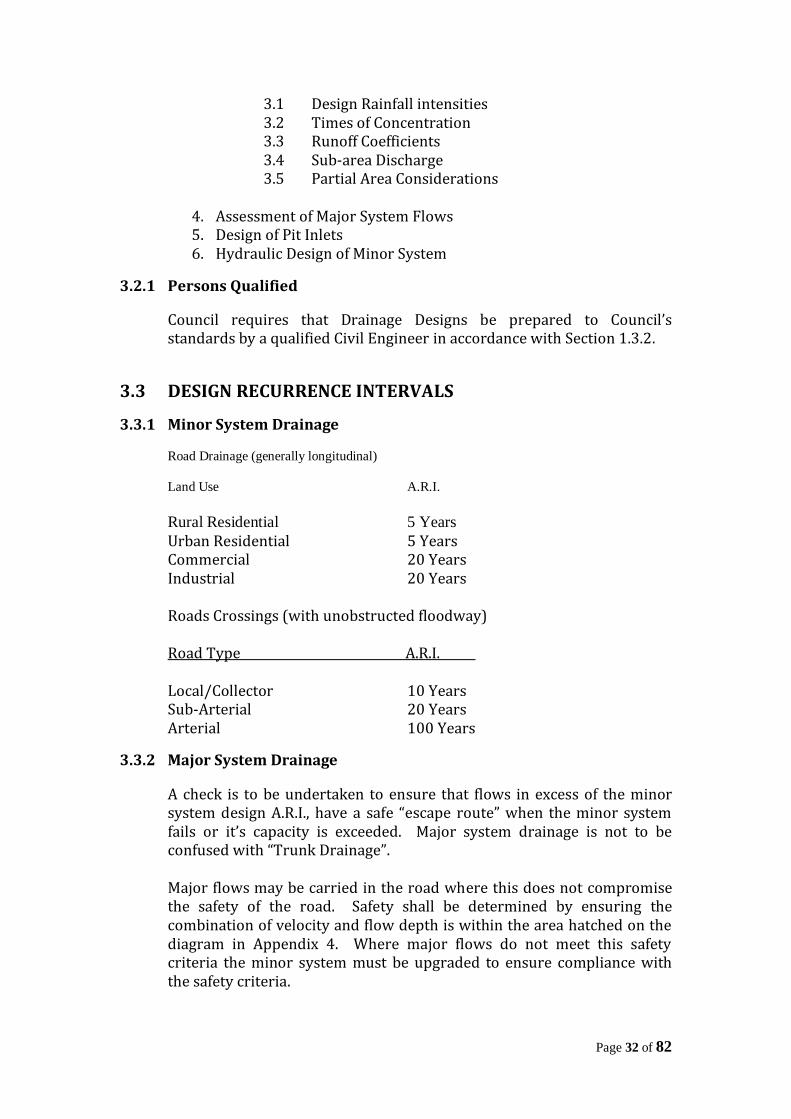
3.1 Design Rainfall intensities 3.2 Times of Concentration 3.3 Runoff Coefficients 3.4 Sub-area Discharge 3.5 Partial Area Considerations
4. Assessment of Major System Flows 5. Design of Pit Inlets 6. Hydraulic Design of Minor System
3.2.1 Persons Qualified
Council requires that Drainage Designs be prepared to Council’s standards by a qualified Civil Engineer in accordance with Section 1.3.2.
3.3 DESIGN RECURRENCE INTERVALS
3.3.1 Minor System Drainage
Road Drainage (generally longitudinal)
Land Use A.R.I.
Rural Residential 5 Years
Urban Residential 5 Years Commercial 20 Years Industrial 20 Years Roads Crossings (with unobstructed floodway) Road Type A.R.I. Local/Collector 10 Years Sub-Arterial 20 Years Arterial 100 Years
3.3.2 Major System Drainage
A check is to be undertaken to ensure that flows in excess of the minor system design A.R.I., have a safe “escape route” when the minor system fails or it’s capacity is exceeded. Major system drainage is not to be confused with “Trunk Drainage”. Major flows may be carried in the road where this does not compromise the safety of the road. Safety shall be determined by ensuring the combination of velocity and flow depth is within the area hatched on the diagram in Appendix 4. Where major flows do not meet this safety criteria the minor system must be upgraded to ensure compliance with the safety criteria.
Page 33 of 82
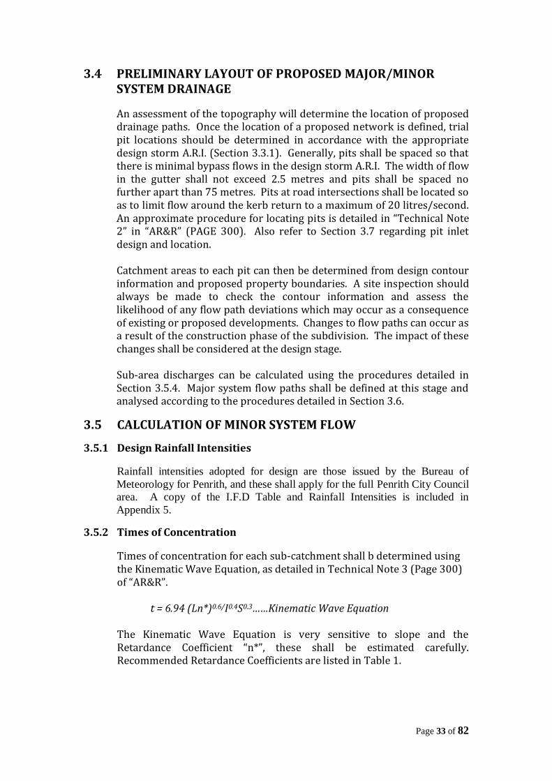
3.4 PRELIMINARY LAYOUT OF PROPOSED MAJOR/MINOR SYSTEM DRAINAGE
An assessment of the topography will determine the location of proposed drainage paths. Once the location of a proposed network is defined, trial pit locations should be determined in accordance with the appropriate design storm A.R.I. (Section 3.3.1). Generally, pits shall be spaced so that there is minimal bypass flows in the design storm A.R.I. The width of flow in the gutter shall not exceed 2.5 metres and pits shall be spaced no further apart than 75 metres. Pits at road intersections shall be located so as to limit flow around the kerb return to a maximum of 20 litres/second. An approximate procedure for locating pits is detailed in “Technical Note 2” in “AR&R” (PAGE 300). Also refer to Section 3.7 regarding pit inlet design and location. Catchment areas to each pit can then be determined from design contour information and proposed property boundaries. A site inspection should always be made to check the contour information and assess the likelihood of any flow path deviations which may occur as a consequence of existing or proposed developments. Changes to flow paths can occur as a result of the construction phase of the subdivision. The impact of these changes shall be considered at the design stage. Sub-area discharges can be calculated using the procedures detailed in Section 3.5.4. Major system flow paths shall be defined at this stage and analysed according to the procedures detailed in Section 3.6.
3.5 CALCULATION OF MINOR SYSTEM FLOW
3.5.1 Design Rainfall Intensities
Rainfall intensities adopted for design are those issued by the Bureau of
Meteorology for Penrith, and these shall apply for the full Penrith City Council
area. A copy of the I.F.D Table and Rainfall Intensities is included in
Appendix 5.
3.5.2 Times of Concentration
Times of concentration for each sub-catchment shall b determined using the Kinematic Wave Equation, as detailed in Technical Note 3 (Page 300) of “AR&R”. t = 6.94 (Ln*)0.6/I0.4S0.3……Kinematic Wave Equation The Kinematic Wave Equation is very sensitive to slope and the Retardance Coefficient “n*”, these shall be estimated carefully. Recommended Retardance Coefficients are listed in Table 1.
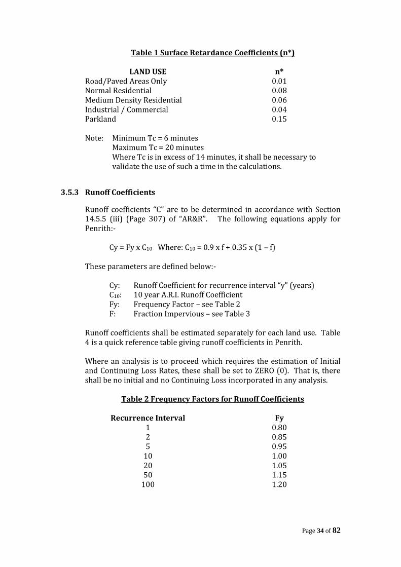
Page 34 of 82
Table 1 Surface Retardance Coefficients (n*)
LAND USE n* Road/Paved Areas Only 0.01 Normal Residential 0.08 Medium Density Residential 0.06 Industrial / Commercial 0.04 Parkland 0.15 Note: Minimum Tc = 6 minutes Maximum Tc = 20 minutes Where Tc is in excess of 14 minutes, it shall be necessary to
validate the use of such a time in the calculations.
3.5.3 Runoff Coefficients
Runoff coefficients “C” are to be determined in accordance with Section 14.5.5 (iii) (Page 307) of “AR&R”. The following equations apply for Penrith:- Cy = Fy x C10 Where: C10 = 0.9 x f + 0.35 x (1 – f) These parameters are defined below:- Cy: Runoff Coefficient for recurrence interval “y” (years) C10: 10 year A.R.I. Runoff Coefficient Fy: Frequency Factor – see Table 2 F: Fraction Impervious – see Table 3 Runoff coefficients shall be estimated separately for each land use. Table 4 is a quick reference table giving runoff coefficients in Penrith. Where an analysis is to proceed which requires the estimation of Initial and Continuing Loss Rates, these shall be set to ZERO (0). That is, there shall be no initial and no Continuing Loss incorporated in any analysis.
Table 2 Frequency Factors for Runoff Coefficients
Recurrence Interval Fy 1 0.80 2 0.85 5 0.95
10 1.00 20 1.05 50 1.15
100 1.20
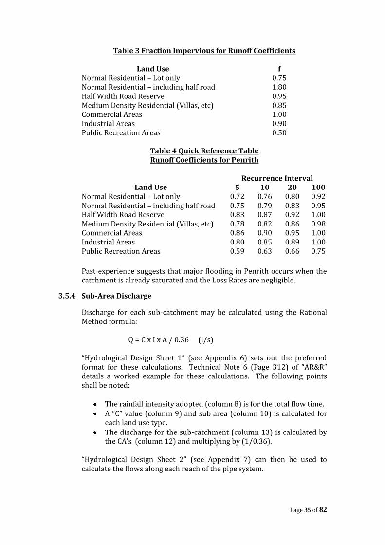
Page 35 of 82
Table 3 Fraction Impervious for Runoff Coefficients
Land Use f Normal Residential – Lot only 0.75 Normal Residential – including half road 1.80 Half Width Road Reserve 0.95 Medium Density Residential (Villas, etc) 0.85 Commercial Areas 1.00 Industrial Areas 0.90 Public Recreation Areas 0.50
Table 4 Quick Reference Table Runoff Coefficients for Penrith
Recurrence Interval
Land Use 5 10 20 100 Normal Residential – Lot only 0.72 0.76 0.80 0.92 Normal Residential – including half road 0.75 0.79 0.83 0.95 Half Width Road Reserve 0.83 0.87 0.92 1.00 Medium Density Residential (Villas, etc) 0.78 0.82 0.86 0.98 Commercial Areas 0.86 0.90 0.95 1.00 Industrial Areas 0.80 0.85 0.89 1.00 Public Recreation Areas 0.59 0.63 0.66 0.75
Past experience suggests that major flooding in Penrith occurs when the catchment is already saturated and the Loss Rates are negligible.
3.5.4 Sub-Area Discharge
Discharge for each sub-catchment may be calculated using the Rational Method formula: Q = C x I x A / 0.36 (l/s) “Hydrological Design Sheet 1” (see Appendix 6) sets out the preferred format for these calculations. Technical Note 6 (Page 312) of “AR&R” details a worked example for these calculations. The following points shall be noted:
The rainfall intensity adopted (column 8) is for the total flow time. A “C” value (column 9) and sub area (column 10) is calculated for
each land use type. The discharge for the sub-catchment (column 13) is calculated by
the CA’s (column 12) and multiplying by (1/0.36). “Hydrological Design Sheet 2” (see Appendix 7) can then be used to calculate the flows along each reach of the pipe system.
Page 36 of 82
3.5.5 Partial Area Flows
In urban catchments, it is possible that a greater flow may be obtained by applying the Rational Method to a lower part of the catchment with a time of concentration less than the full area travel time. These partial areas effects commonly occur when large paved areas are directly connected to the pipe inlet, and the sub-catchment discharge is based on a larger pervious area. Similarly, partial area effects can also occur, where a large open space catchment contributes to an urban catchment, with a Time of Concentration substantially different to the urban catchment. In areas where this may be critical, such as industrial or high density residential development, a partial area check, based on time of concentration of impervious areas directly connected to the pipe system, is necessary.
3.6 ASSESSMENT OF MAJOR SYSTEM FLOWS
All urban drainage designs shall incorporate an assessment of major system flows. The aim of this check is to ensure that a safe and adequate “escape route” is achieved for large storm events. The Rational Method may be used to estimate major system flows for critical points in the drainage system. An A.R.I. of 100 years shall be used for this and the difference between the minor system flow and the 100 year A.R.I. flow shall be the basis upon which the major system flow path shall be designed. The roads and pathways will generally form the flow path by which the major system flows are routed, either to the trunk drainage system or to a low point with sufficient hydraulic capacity to capture the flows. Special consideration needs to be given to trapped low points where the overland flowpath may divert surcharge into properties. This is especially important when designing a “Downhill” cul-de-sac or kerb returns adjacent to a sag vertical curve. In the latter case consideration shall be given to grading the kerb return such that water flows around the return and away before it breaks over the top of kerb at the low point. Technical Note 4 (page 304) of “AR&R” details a method for calculating gutter and road flows. If the roadway capacity is inadequate, an estimate shall be made of the capacity of the pipe system under major flow conditions. Pit capacities shall be calculated using the appropriate blocking factors, and pipe capacities estimated with trial diameters and head levels no greater than 150mm below the surface levels / invert of kerb (applicable up to the design A.R.I. for the respective pipeline reach). The computer program listed on page 318 of “AR&R” will calculate pipe capacities for this purpose.
Page 37 of 82
The major flows must have an overland flow path such that all habitable floor levels are a minimum of 0.5m above the 100 year A.R.I. Top Water Level. The freeboard requirement may be varied by Council’s Engineer on consideration of the sensitivity of the floodway parameters to the flows. Technical Note 6 (page 309) in “AR&R” details a procedure for checking major system flows. A copy of “Hydrological Design Sheet 3” the preferred format for checking major systems, is included in Appendix 8.
3.7 PIT INLET DESIGN
3.7.1 Pit Location
The following criteria governs the location of pits in roadways, for the minor system design A.R.I.
1. Inlets Pits are to be spaced so that flow width shall not exceed 80 litres/sec.
2. Velocity and depth shall fall within the hatched area as shown in Appendix 4.
3. Bypass from any pit on grade is not to exceed 15% of the total flow at the pit (full capture desirable).
4. Maximum spacing between pits shall not exceed 75m. 5. Where flows in the gutter exceed 20 l/s and/or are greater than
1m in width, adjacent to the upstream Kerb Return Tangent Point, it will be necessary to intercept these flows with a Kerb Inlet Pit.
6. The location of gully pits on curves is to be avoided and they are not to be place in line with the normal passage of pedestrians.
Technical Note 4 (page304) “AR&R” details a method for calculating gutter and road flows.
3.7.2 Inlet Design
Once the sub-catchment flows are known, pit inlets shall be designed in accordance with the charts contained on the following pages. All new pit inlets are to be constructed using bicycle safe welded steel (Weldlok” or similar) type grates which allow access to the pit. On grade, percentage capture by grates is mainly dependent on lintel size. Calculations for the design of pit inlets is to be tabulated on “Hydrological Design Sheet 1” of “AR&R (column 16 to 20). Sag pits are to be designed based on a depth of ponding, up to the top of the kerb. Minimum internal lintel size in a sag pit shall be 2.4m.
Page 38 of 82
3.8 DRAINAGE PIT DESIGN
3.8.1 General
1. Standard pits shall be provided in drainage lines at all changes in grade, level or direction and at all pipe junctions;
2. The minimum clearance from the top of the manhole to the design
water level in the pit shall be 150mm;
3. Pipe junctions where the deflection angle of the larger flow is 90° or more, should be avoided;
4. Grading across pits shall be designed on the following basis:-
No change in direction or pipe diameter – minimum
50mm; Change in direction only – minimum 70mm; Changes in pipe diameter shall be graded obvert to
obvert;
5. Where the depth of the pit exceeds 1.2 metres, galvanised or other approved step-irons are to be provided at a spacing of 300mm to provide access for inspection and cleaning;
6. Pits shall be constructed of sufficient internal dimensions to avoid
“birdsmouthing” of pipes.
7. Inter-allotment drainage pits shall have minimum internal dimensions of 600mm x 600mm. The minimum internal dimensions of all other drainage pits shall be 900mm x 600mm.
8. Pit walls are to be a minimum 150mm thick and shall be formed on
both the inside the outside faces.
9. Pits are to be located and constructed in accordance with Council’s standard drawings.
10. Where drainage pits exceed 1.5 metres in depth, the pit shall be
constructed of reinforced concrete.
3.8.2 Kerb Inlet Pits
Are to be constructed in accordance with Penrith City Council’s Standard Drawing SD2001.
Page 39 of 82
3.8.3 Junction Pits
Are to be constructed in accordance with Penrith City Council’s Standard Drawing No. S802
3.8.4 Surface Inlet and Surcharge Pits
Are to be constructed in accordance with Penrith City Council’s Standard Drawing SD2002.
3.9 PIPELINE DESIGN
3.9.1 General Requirements
a) Pipelines in roadways shall have a minimum diameter of 375mm.
b) Pipelines should cross roads so as to minimise deflection angles and pit losses (45° desirable maximum).
c) Drainage shall not be carried a greater distance than 75 metres in
pipelines without adequate inspection manholes.
d) For single cell pipe systems, a downstream pipe of smaller diameter than the upstream pipe will not be permitted.
e) A desirable minimum grade of 1% for all pipelines is preferred for
self-cleansing under low flow velocities. Flow velocities should exceed 0.6m/s for self cleansing purposes.
f) The inlet and outlet drains to pipelines shall be carefully designed
so as to avoid either scouring or silting velocities during storm flows, and adequate scour protection satisfactory to Council’s Engineer is to be provided at the outlet of all stormwater lines.
g) Curved pipelines should generally be avoided. Where curved
pipelines are proposed, they are to be installed strictly in accordance with the Manufacturer’s recommended minimum radii.
h) Pipelines shall not be laid longitudinally within the footway area.
3.9.2 Headwalls
Concrete headwalls are to be provided as indicated on the approved Engineering Drawings or where directed by Council’s Engineer. Concrete headwalls shall be either Precast or constructed in-situ.
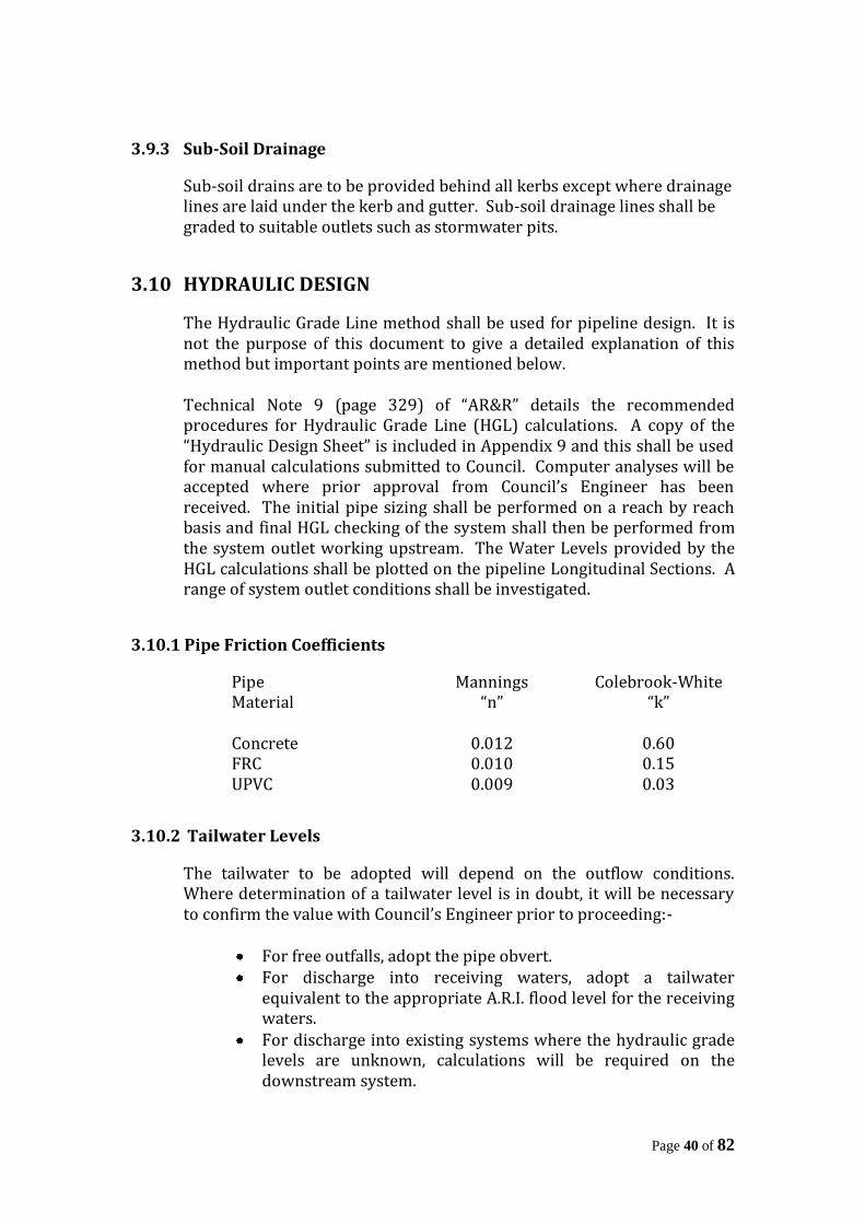
Page 40 of 82
3.9.3 Sub-Soil Drainage
Sub-soil drains are to be provided behind all kerbs except where drainage lines are laid under the kerb and gutter. Sub-soil drainage lines shall be graded to suitable outlets such as stormwater pits.
3.10 HYDRAULIC DESIGN
The Hydraulic Grade Line method shall be used for pipeline design. It is not the purpose of this document to give a detailed explanation of this method but important points are mentioned below. Technical Note 9 (page 329) of “AR&R” details the recommended procedures for Hydraulic Grade Line (HGL) calculations. A copy of the “Hydraulic Design Sheet” is included in Appendix 9 and this shall be used for manual calculations submitted to Council. Computer analyses will be accepted where prior approval from Council’s Engineer has been received. The initial pipe sizing shall be performed on a reach by reach basis and final HGL checking of the system shall then be performed from the system outlet working upstream. The Water Levels provided by the HGL calculations shall be plotted on the pipeline Longitudinal Sections. A range of system outlet conditions shall be investigated.
3.10.1 Pipe Friction Coefficients
Pipe Material
Mannings “n”
Colebrook-White “k”
Concrete 0.012 0.60 FRC 0.010 0.15 UPVC 0.009 0.03
3.10.2 Tailwater Levels
The tailwater to be adopted will depend on the outflow conditions. Where determination of a tailwater level is in doubt, it will be necessary to confirm the value with Council’s Engineer prior to proceeding:-
For free outfalls, adopt the pipe obvert. For discharge into receiving waters, adopt a tailwater
equivalent to the appropriate A.R.I. flood level for the receiving waters.
For discharge into existing systems where the hydraulic grade levels are unknown, calculations will be required on the downstream system.
Page 41 of 82
For discharge into a point designed to surcharge, adopt a tailwater level equivalent to the height of surcharge.
3.10.3 Inlet Efficiency
An allowance of 150mm is to be adopted below the lowest point of the pit inlet/kerb invert, to effectively allow such inlets to act efficiently. Where this cannot be achieved it will be necessary to obtain the concurrence of Council’s Engineer before proceeding.
3.10.4 Pit Loss Factors Pit loss factors (k) shall be calculated using the Tables from A.R.R.B. SR 34, 1988 (Tables 6.5 and 6.6). Where the pit configuration is not covered by these tables, the Missouri Charts, Hare Charts or Department of Housing Charts should be used. The top pit in the system must have sufficient depth to generate enough head to charge the pipe. This can be calculated by using an appropriate pit loss factor (k) which shall not be less than 4.5.
3.11 DRAINAGE EASEMENTS
Where it is intended to create drainage easements for a new road provided in a subdivision, a notation should appear on the Engineering Drawings and subdivision plan creating the easement or easements pursuant to Section 88B of the Conveyancing Act, 1919 as amended. Where stormwater drainage conveyed in a drainage easement, piped or otherwise, would discharge onto land other than an existing drainage easement or public place, it shall be the responsibility of the Applicant to obtain a drainage easement through such land, sufficient in dimension to convey the drainage to an easement, natural watercourse or public place, and to transfer easement rights thereover to Council. The linen plan of subdivision will not be released until the above requirements have been complied with, and all fees and contributions have been paid. Where a drainage easement lies within a development which does not involve the opening of a new road, the applicant shall transfer to Council any drainage easement provided in the subdivision and execute a transfer and grant of easement in favour of Council pursuant to Section 88B of the Conveyancing Act, 1919 as amended. Drainage easements are generally to be piped within the subdivision, if not otherwise approved by Council’s Engineer. In parkland, pipes sufficient to carry a 1 in 1 year frequency storm and the dry weather flow shall be installed plus an open grassed channel to meet
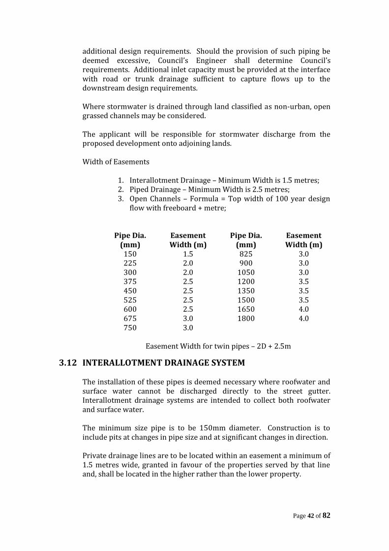
Page 42 of 82
additional design requirements. Should the provision of such piping be deemed excessive, Council’s Engineer shall determine Council’s requirements. Additional inlet capacity must be provided at the interface with road or trunk drainage sufficient to capture flows up to the downstream design requirements. Where stormwater is drained through land classified as non-urban, open grassed channels may be considered. The applicant will be responsible for stormwater discharge from the proposed development onto adjoining lands. Width of Easements
1. Interallotment Drainage – Minimum Width is 1.5 metres; 2. Piped Drainage – Minimum Width is 2.5 metres; 3. Open Channels – Formula = Top width of 100 year design
flow with freeboard + metre;
Pipe Dia.
(mm) Easement Width (m)
Pipe Dia. (mm)
Easement Width (m)
150 1.5 825 3.0 225 2.0 900 3.0 300 2.0 1050 3.0 375 2.5 1200 3.5 450 2.5 1350 3.5 525 2.5 1500 3.5 600 2.5 1650 4.0 675 3.0 1800 4.0 750 3.0
Easement Width for twin pipes – 2D + 2.5m
3.12 INTERALLOTMENT DRAINAGE SYSTEM The installation of these pipes is deemed necessary where roofwater and surface water cannot be discharged directly to the street gutter. Interallotment drainage systems are intended to collect both roofwater and surface water. The minimum size pipe is to be 150mm diameter. Construction is to include pits at changes in pipe size and at significant changes in direction. Private drainage lines are to be located within an easement a minimum of 1.5 metres wide, granted in favour of the properties served by that line and, shall be located in the higher rather than the lower property.
Page 43 of 82
At the most suitable point in each lot, a junction is to be provided. Prior to backfilling, the location and depth of the junction is to be recorded and this information is to be shown on the W.A.E. drawings.
3.13 DESIGN PRESENTATION
Generally, drainage designs are to be presented in the form shown in chapter 14 of “AR&R”. The following data is to be provided in association with a contoured catchment area plan, the scale of which should not be less than 1:2000:-
a) Catchment areas, paths of overland flow and proposed and exiting pipe layout, plan with all sub-areas, drainage lines and manholes numbered;
b) Area of catchment sub-areas (the area drained by each headwall,
pit or any other pick-up point);
c) Length, slope and time of overland flow;
d) Length, slope and time of gutter flow;
e) Sub-area and critical times of concentration;
f) Coefficients of runoff;
g) Rainfall intensities;
h) Design discharges;
i) Slope of hydraulic gradients, corresponding velocities and times of flow;
j) Hydraulic grade levels at manholes;
k) Size, length, slope and invert levels of proposed drainage lines;
l) The accurate position and levels of all services crossed by any
stormwater pipeline;
m) Longitudinal sections for all drainage lines;
n) Cross-sections where necessary;
o) The minimum habitable floor levels for all lots adjacent to major stormwater flow paths shall be clearly indicated;

Page 44 of 82
p) Tailwater Levels;
q) Site contours shall be indicated on the stormwater plan;
r) Open channels shall be detailed with cross-sections at a maximum spacing of 20 metres;
s) Longitudinal sections for all open channels with backwater
profiles.
Page 45 of 82
Page 46 of 82
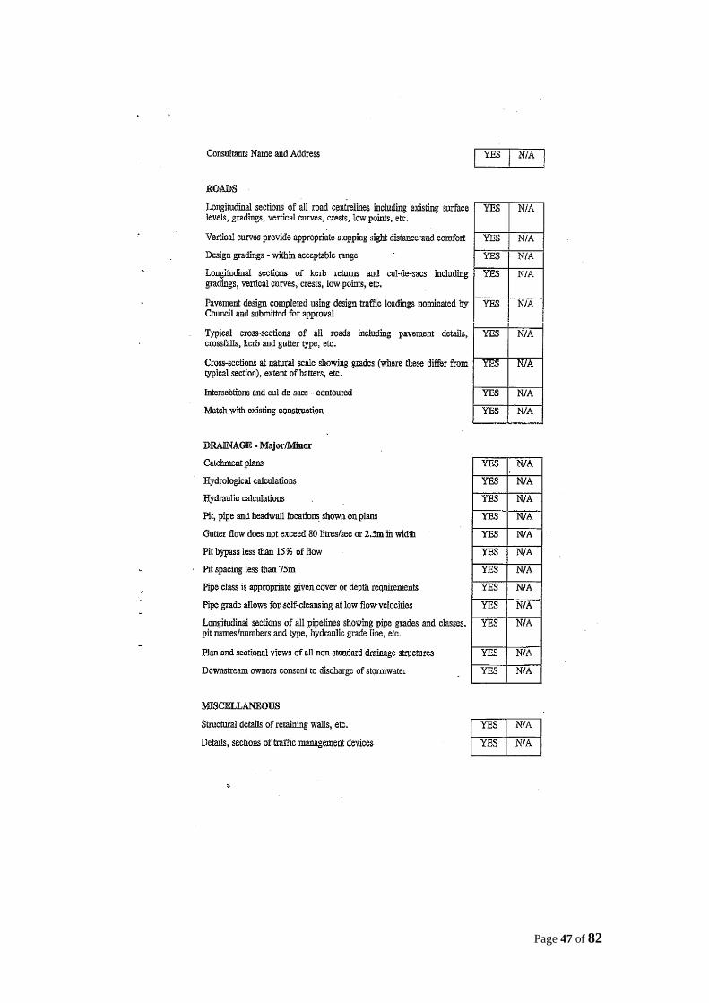
Page 47 of 82
Page 48 of 82

Page 49 of 82
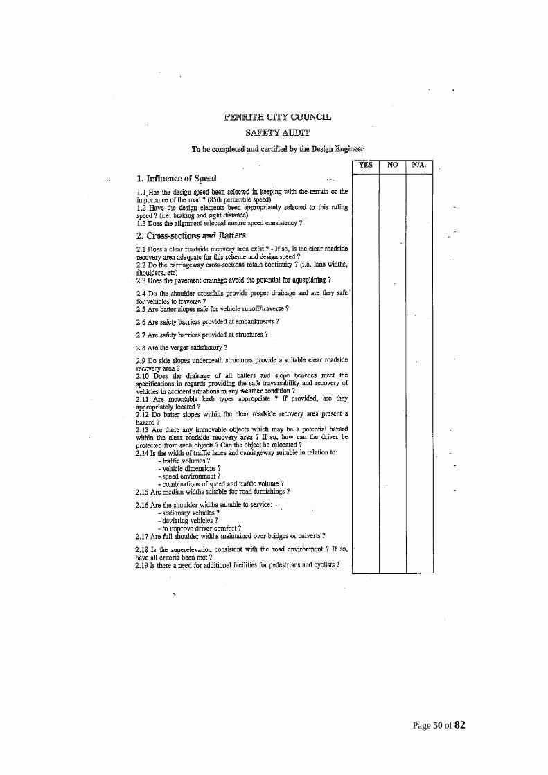
Page 50 of 82
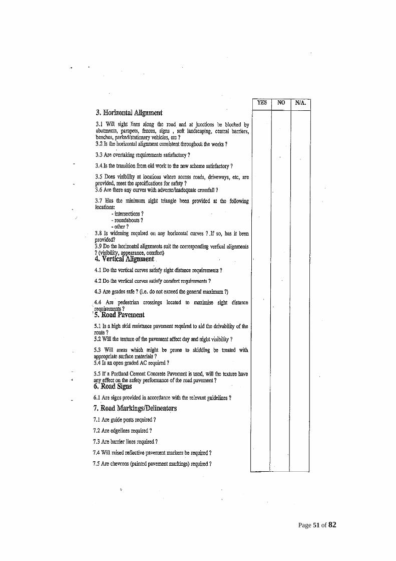
Page 51 of 82
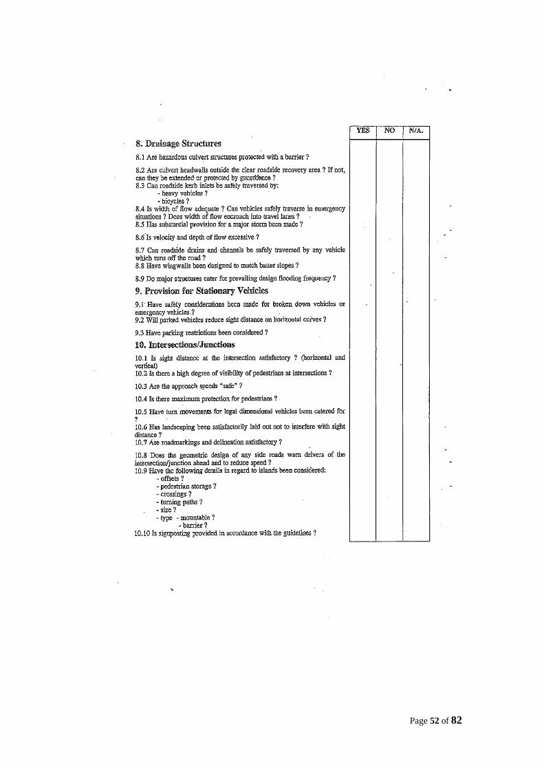
Page 52 of 82
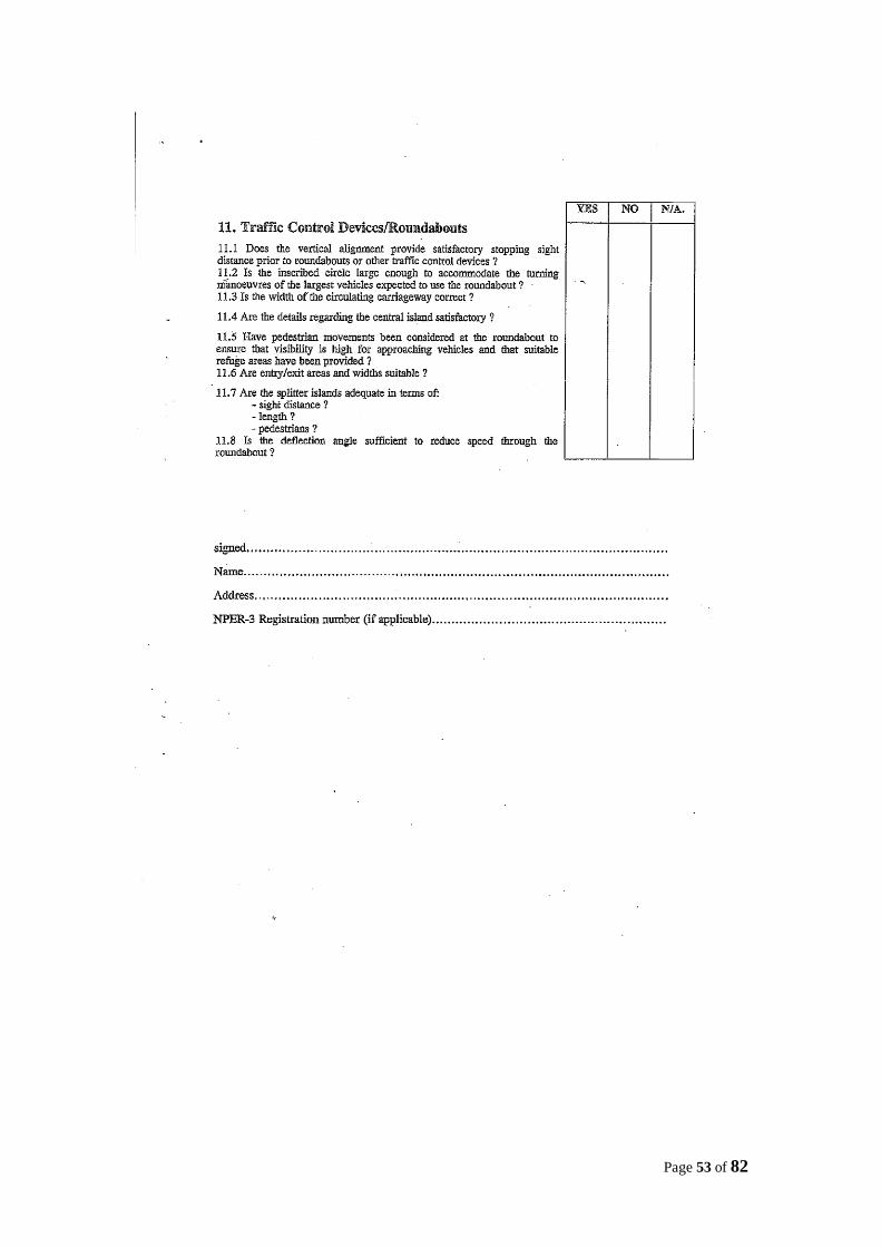
Page 53 of 82
Page 54 of 82
Page 55 of 82
Page 56 of 82
Page 57 of 82
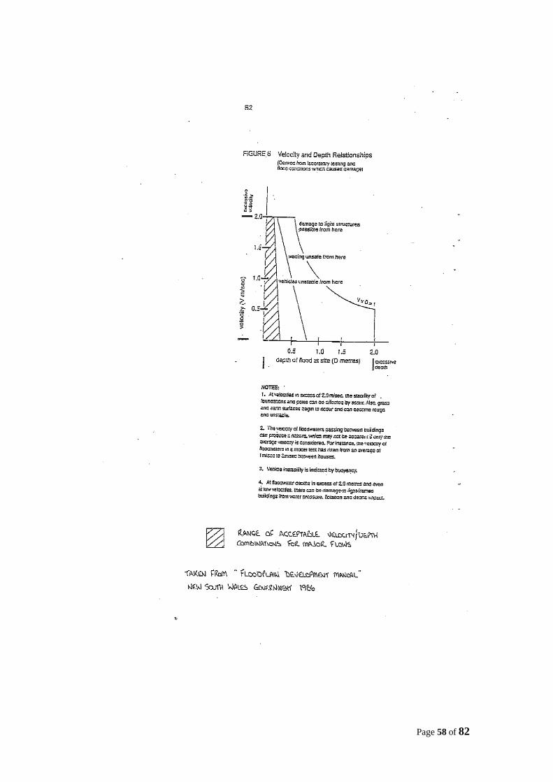
Page 58 of 82
Page 59 of 82
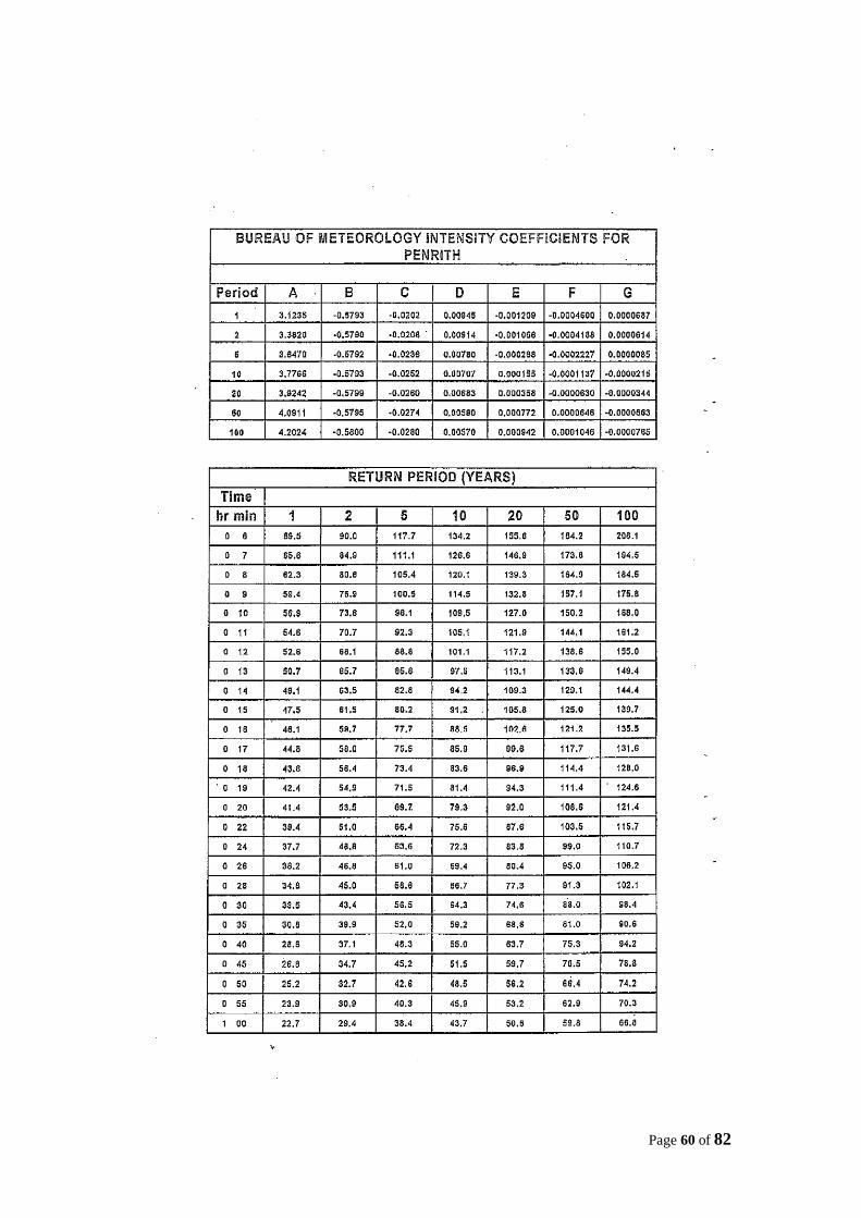
Page 60 of 82
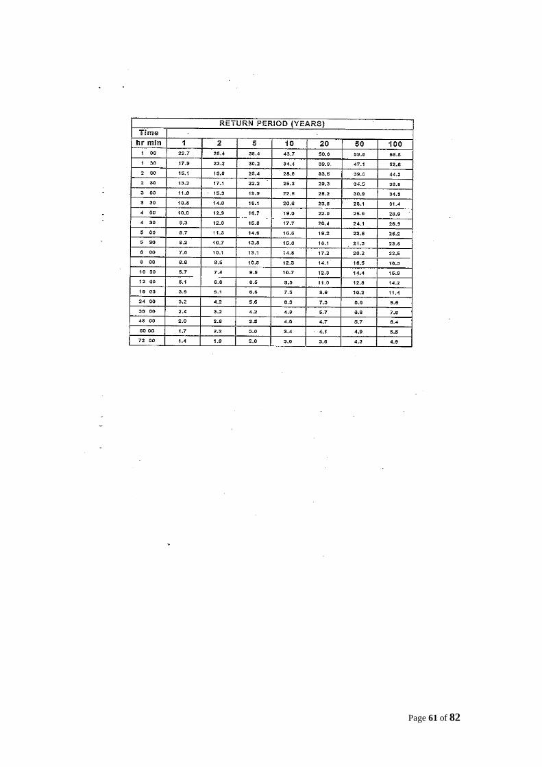
Page 61 of 82

Page 62 of 82
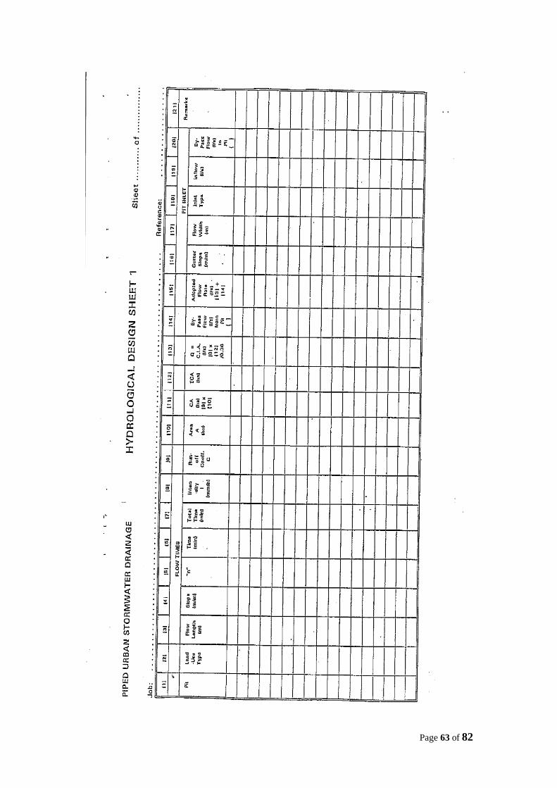
Page 63 of 82
Page 64 of 82
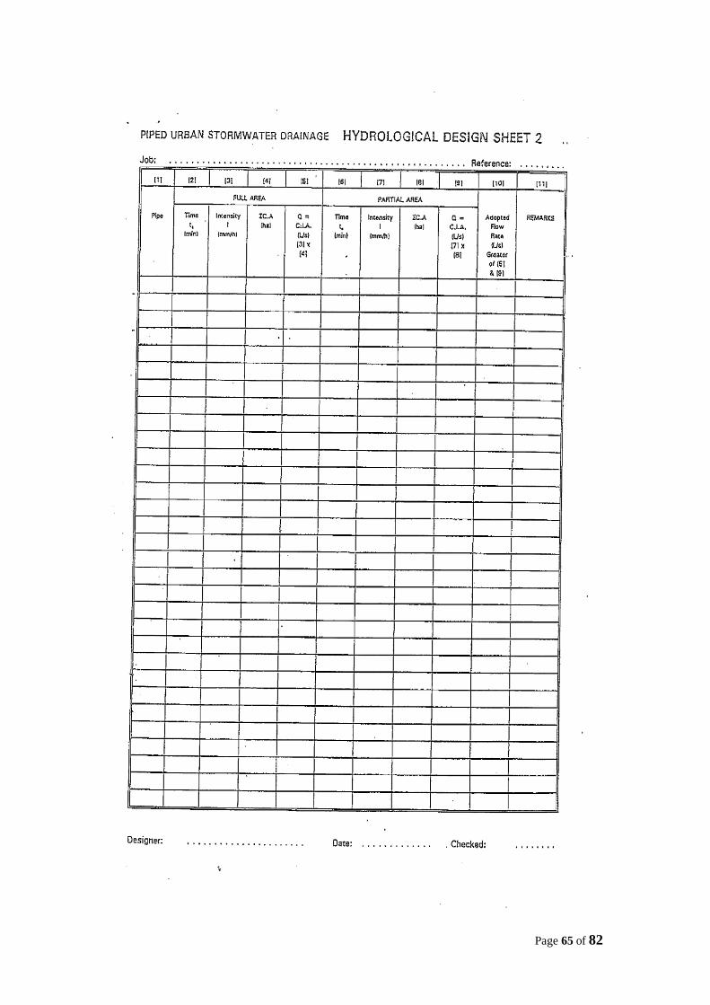
Page 65 of 82
Page 66 of 82
Page 67 of 82
Page 68 of 82
Page 69 of 82
Page 70 of 82
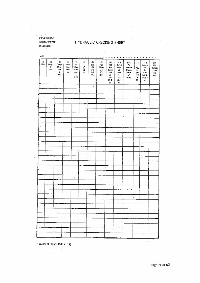
Page 71 of 82

Page 72 of 82
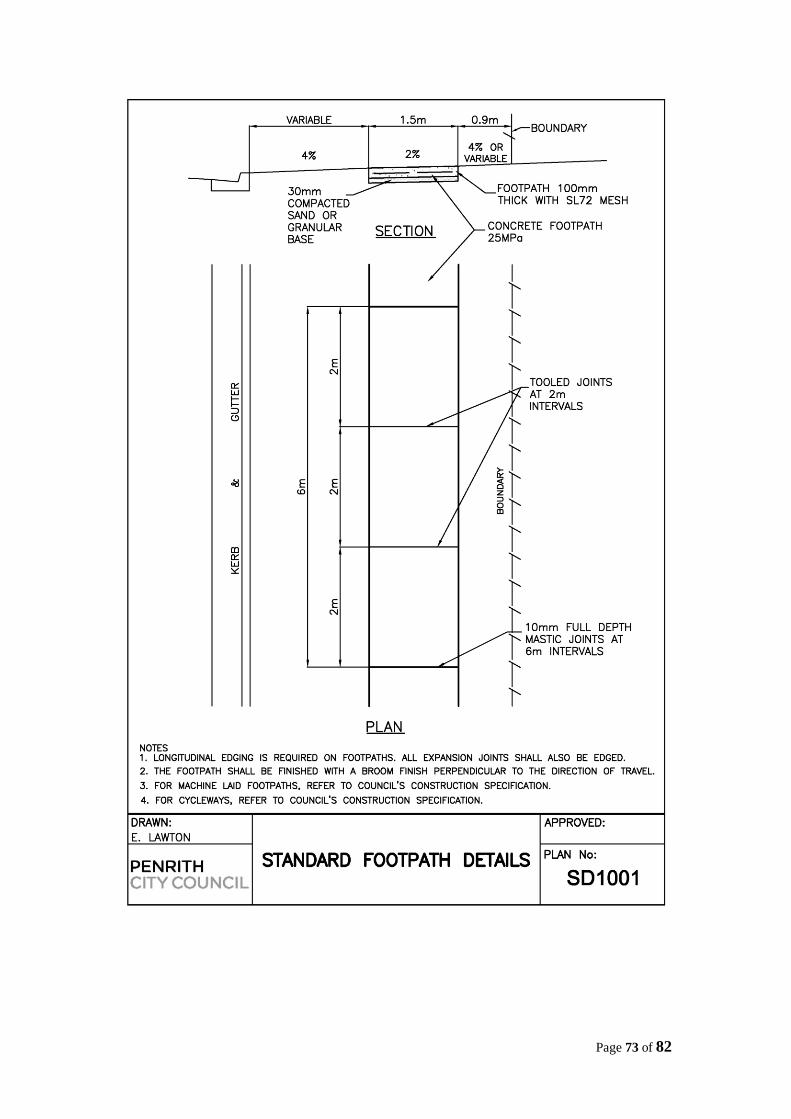
Page 73 of 82
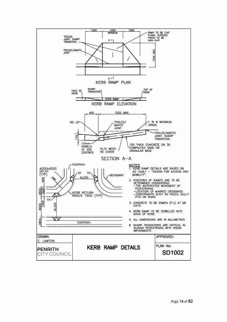
Page 74 of 82
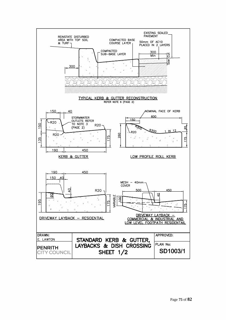
Page 75 of 82
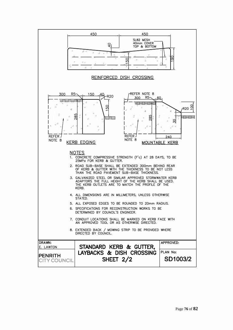
Page 76 of 82

Page 77 of 82
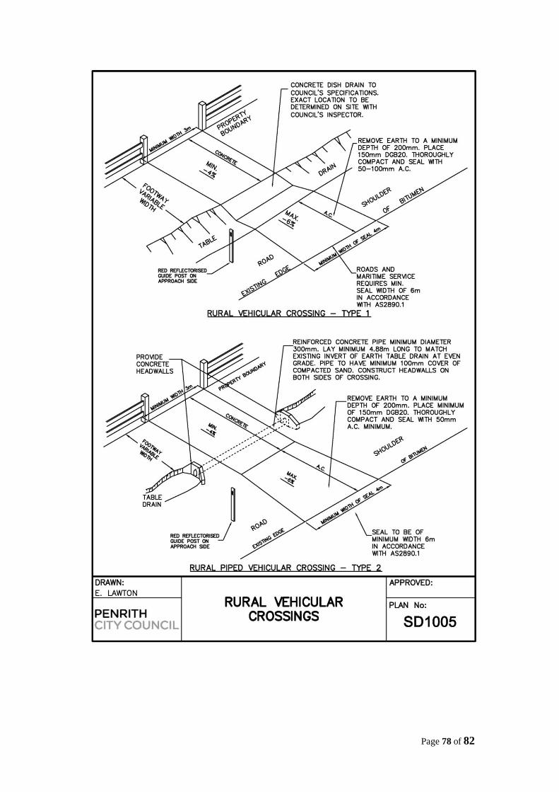
Page 78 of 82
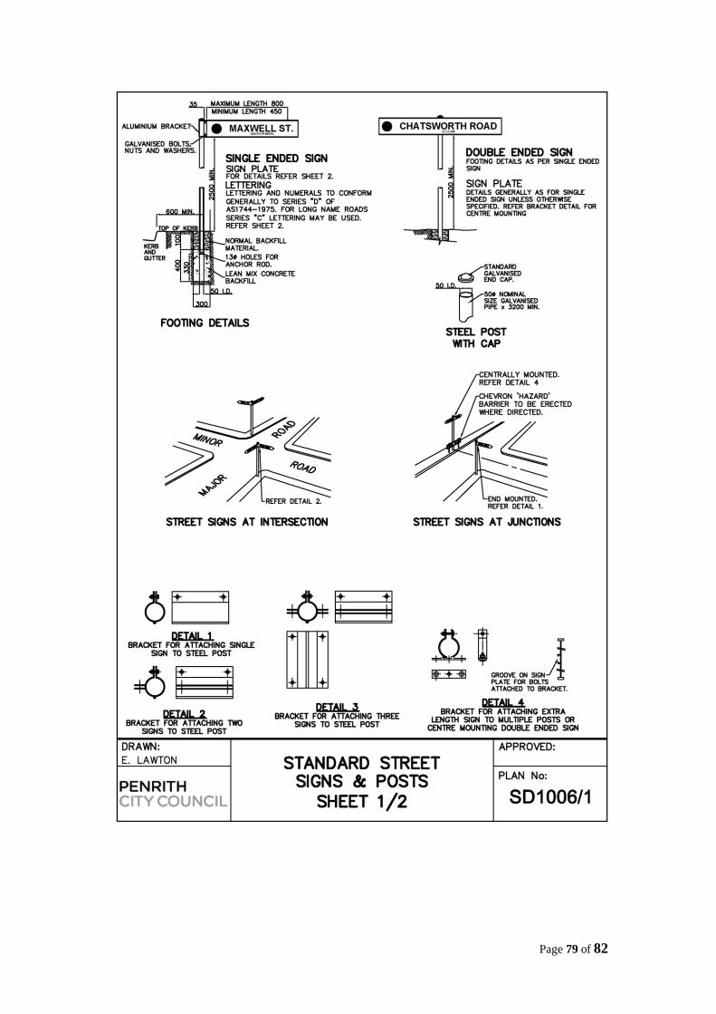
Page 79 of 82
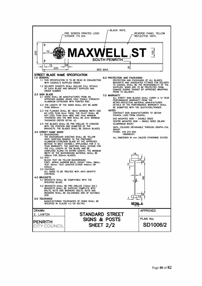
Page 80 of 82
Page 81 of 82
Page 82 of 82