Embed Size (px)
Citation preview

1
Design, Implementation, and Evaluation of aQoS-Aware Real-Time Embedded Database
Woochul Kang, Sang H. Son, Senior Member, IEEE, and John A. Stankovic, Fellow, IEEE
Abstract—QeDB (Quality-aware real-time Embedded DataBase) is a database for data-intensive real-time applications running on
embedded devices. Currently, databases for embedded systems are best effort, providing no guarantees on their timeliness and data
freshness. Existing real-time database (RTDB) technology cannot be applied to these embedded databases since it hypothesizes that
the main memory of a system is large enough to hold the entire database. This, however, might not be true in data-intensive real-time
applications. QeDB uses a novel feedback control scheme to support QoS in such embedded systems without requiring all data to
reside in main memory. In particular, our approach is based on simultaneous control of both I/O and CPU resources to guarantee the
desired timeliness. Unlike existing work on feedback control of RTDB performance, we implement and evaluate the proposed scheme
on a modern embedded device. The experimental results show that our approach supports the desired timeliness of transactions while
still maintaining high data freshness compared to baseline approaches.
Index Terms—Real-time database, embedded database, transaction tardiness, sensor data freshness, QoS management, feedback
control, Multiple Inputs/ Multiple Outputs (MIMO) control.
F
1 INTRODUCTION
Recent advances in sensor technology and wireless connec-
tivity have paved the way for next generation real-time ap-
plications that are highly data-driven, where data represent
real-world status [1]. For many of these applications, data
from sensors are managed and processed in application-
specific embedded systems with certain timing constraints. For
example, control units of an automobile collect and process a
large volume of real-time data not only from internal sensors
and devices [2], but also from external environments such as
nearby cars and intelligent roads [3][4]. Another examples are
PDAs carried by firefighters for search-and-rescue tasks. These
PDAs collect real-time sensor data from both the burning
building and other firefighters. They also process the data to
check the dynamically changing status of the fire scene and
alert in a timely fashion if there is a potential danger to the
firefighters. [5][6]. In these applications, ad-hoc management
of data can increase the difficulty of development due to ever
increasing complexity and size of data. Hence, it is essential
to provide a systematic mechanism to manage the data.
An embedded database [7] is an integral part of such
applications or application infrastructures. Unlike traditional
DBMSs, database functionality is delivered as part of the
application or application infrastructure. These databases run
with or as part of the applications in embedded systems. Em-
bedded databases provide an organized mechanism to access
large volumes of data for applications. Instead of providing
full features of traditional DBMSs, such as complex query
• W. Kang is with Electronics and Telecommunication Research In-
stitute (ETRI), 138 Gajeongno, Yuseong-gu, Daejon, Korea. E-mail:
• S.H. Son, and J.A. Stankovic are with the Department of Computer
Science, University of Virginia, 151 Engineer’s Way, PO Box 400740,
Charlottesville, VA. E-mail: {son,stankovic}@cs.virginia.edu
optimization and handling mechanisms, embedded databases
provide minimal functionality such as indexing, concurrency
control, logging, and transactional guarantees. Several off-the-
shelf embedded databases are available such as Berkeley DB
[8], and SQLite [9]. However, these embedded databases are
unaware of timing and data freshness requirements, showing
poor performance in real-time applications [10].
Achieving timeliness of tasks has been a core research issue
in the real-time systems domain, and it has been actively
investigated [11][12]. Unfortunately, applying those results to
the emerging data-intensive real-time applications and embed-
ded databases has several problems. One main difficulty lies
in the inappropriate real-time task model of traditional real-
time computing work. In particular, most real-time research
has been focused on computation-intensive applications. This
work assumes that all data resides in main memory for real-
time tasks, which might not be true in data-intensive real-
time applications. This assumption has been mainly used
to eliminate the highly unpredictable response time of I/O
operations to disks.
To address these problems, we have designed and im-
plemented a real-time embedded database (RTEDB), called
QeDB (Quality-aware Embedded DataBase). QeDB has been
designed particularly for embedded devices for data-intensive
applications, where not all the data can be fit into main-
memory. For such applications, QeDB provides a storage
abstraction layer that virtualizes the underlying storage devices
while guaranteeing the desired timeliness of transactions ac-
cessing data via the abstraction layer. To the best of our knowl-
edge, this is the first paper on providing Quality-of-Service
(QoS) for embedded databases with a real implementation.
The contributions of this paper are as follows:
1) Real-time transaction model for RTEDBs: In QeDB, a
real-time transaction is defined as a real-time task that accesses
data through a RTEDB with optional transaction guarantees.
2
For example, real-time transactions of a firefighter’s PDA
run periodically to retrieve the up-to-date sensor data by
issuing requests to the underlying RTEDB and also perform
computational tasks such as checking the potential dangers,
and finding safe paths. Because real-time transactions consist
of both data accesses and computation with the retrieved data,
the timeliness of these transactions is determined not only by
their computational activities, but also by their I/O activities.
Further, our observations show that the response time of a
transaction’s computational activities is highly affected by its
I/O activities, and vice versa. For instance, decreasing the size
of buffer cache in RTEDBs increases not only the average I/O
response time, but also the CPU load because more frequent
buffer management activities, e.g., searching for least-recently-
used pages, are required due to low buffer hit ratio. This close
interaction between computation load and I/O load implies that
the QoS of transactions can be guaranteed only when both I/O
and computation are considered simultaneously.
2) A novel feedback control architecture: In QeDB, the
metrics for QoS are the timeliness of transactions and the
freshness of data, which may pose conflicting requirements
[13]. QeDB achieves the desired QoS using a novel feed-
back control technique. Even though feedback control has
recently been applied to RTDB to systematically trade data
freshness for the timeliness of transactions in the presence
of dynamic workloads [14][15], these approaches control a
single resource, i.e., CPU load, to achieve the QoS goals. In
contrast, QeDB exploits a Multiple Inputs/Multiple Outputs
(MIMO) modeling and controller design technique to capture
the close interactions of multiple control inputs (CPU load and
I/O load) and the multiple system outputs (the timeliness of
I/O operations and computation). The MIMO controller adjusts
both CPU load and I/O load simultaneously.
3) Implementation: Most RTDB work is based on simulation
and some assumptions are too rigid to implement. Hence,
there were limitations in modeling real system behaviors
and workloads. Very little prior work, such as [16][10][17],
has evaluated real-time data management techniques in real
database systems. QeDB has been implemented by extending
Berkeley DB [8], which is a popular open-source embedded
database, to support a target QoS. QeDB does not require
particular support from underlying operating systems; it relies
only on the standard real-time features of POSIX [18].
4) Evaluation: QeDB has been implemented and evaluated
on a real embedded device with realistic workloads. The
evaluation results demonstrate that MIMO control of QoS
in QeDB is significantly more effective than the baseline
approaches. In particular, QeDB makes a better negotiation
between the timeliness of transactions and the freshness of
data by providing proper amount of resources in a robust and
controlled manner.
The rest of the paper is organized as follows. Section
2 presents the overview of real-time transactions and data
model in QeDB. Section 3 describes the QeDB architecture
and feedback control procedure. In Section 4, we discuss the
details of feedback control mechanism in QeDB. In Section
5, implementation issues are discussed. Section 6 shows the
details of the evaluation settings and presents the evaluation
results. Related work is presented in Section 6 and Section 7
concludes the paper and discusses future work.
2 OVERVIEW OF QEDB
2.1 System Model
QeDB targets real-time embedded devices, which have rel-
atively small main memory compared to their secondary
storage. Since the capacity of the secondary storage is usually
far greater than the size of main memory, databases bigger than
the main memory can be used with support from the secondary
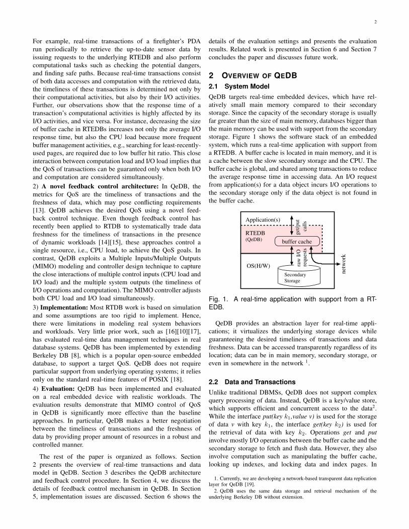
storage. Figure 1 shows the software stack of an embedded
system, which runs a real-time application with support from
a RTEDB. A buffer cache is located in main memory, and it is
a cache between the slow secondary storage and the CPU. The
buffer cache is global, and shared among transactions to reduce
the average response time in accessing data. An I/O request
from application(s) for a data object incurs I/O operations to
the secondary storage only if the data object is not found in
the buffer cache.
(QeDB)
Application(s)
OS(H/W)
RTEDB
Secondary
Storage
raw
I/O
req
ues
ts
buffer cache
net
work
get
/pu
t
call
sFig. 1. A real-time application with support from a RT-
EDB.
QeDB provides an abstraction layer for real-time appli-
cations; it virtualizes the underlying storage devices while
guaranteeing the desired timeliness of transactions and data
freshness. Data can be accessed transparently regardless of its
location; data can be in main memory, secondary storage, or
even in somewhere in the network 1.
2.2 Data and Transactions
Unlike traditional DBMSs, QeDB does not support complex
query processing of data. Instead, QeDB is a key/value store,
which supports efficient and concurrent access to the data2.
While the interface put(key k1,value v) is used for the storage
of data v with key k1, the interface get(key k2) is used for
the retrieval of data with key k2. Operations get and put
involve mostly I/O operations between the buffer cache and the
secondary storage to fetch and flush data. However, they also
involve computation such as manipulating the buffer cache,
looking up indexes, and locking data and index pages. In
1. Currently, we are developing a network-based transparent data replicationlayer for QeDB [19].
2. QeDB uses the same data storage and retrieval mechanism of theunderlying Berkeley DB without extension.
3
this paper, I/O operations refer to put and get operations in
QeDB, which include not only raw I/O operations to secondary
storages, but also computation required for the I/O operations.
Data objects in QeDB can be classified into two classes,
temporal and non-temporal data. Temporal data objects are
updated periodically by update transactions. For example,
an update transaction is issued when a new sensor reading
becomes available. In contrast to update transactions, user
transactions may read and modify both temporal and non-
temporal data objects. The operations of transactions are
hard-coded into the applications, and invoked dynamically
at runtime. The characteristics of a transaction, such as its
execution time and access pattern, are known at design time.
However, the workload and data access pattern of the whole
database is unpredictable and changes dynamically because the
invocation frequency of each transaction is unknown and mul-
tiple transactions execute concurrently. Hence, their response
times can be unpredictable. Transactions access data through
QeDB and transactional properties such ACID (atomicity,
consistency, isolation, and durability) between data accesses
are provided if they are specified by the applications.
Program 1 shows an example of a transaction that is invoked
periodically in a firefighter’s PDA to check the structural
integrity of the building3. Note that the PDA not only performs
I/O operations to get/put data, but also computations that
check the integrity of the structure. The logical consistency
of the data accesses can be guaranteed by enclosing all or
part of the transaction with begin transaction and commit (or
abort). However, logical consistency is not required for all
transactions and it is application-dependent.
Program 1 A transaction checking the integrity of a structure.trx_check_structure_integrity()
{
/* A list of keys to sensor data to process */
DBT key_displacement_sensors={Sen_1,Sen_2,..., Sen_n}
/* memory to copy in sensor data */
DBT data_sensors[NUM_SENSORS];
/* Some computation */
init();
/* perform I/Os by reading in data from the DB */
for (i=0; i< NUM_SENSORS; i++){
data_sensors[i]= get(key_displacement_sensors[i]);
}
/* computation */
status = analyze_integrity(data_sensors);
/* another I/O */
put(key_status, status);
}
2.3 Real-Time Transactions
Transactions can be classified as two categories: real-time
transactions and non-real-time transactions. Real-time trans-
actions are real-time tasks, which have deadlines on their com-
pletion time, and they have higher priority than non-real-time
transactions. For instance, the transaction in Program 1 should
report the status of the structural integrity of the burning
3. Some details are not shown for clarity and readability.
building within a specified deadline; otherwise, the firefighters
may lose a chance to escape from a dangerous place that
might collapse. We apply soft deadline semantics, in which
transactions still have value even if they miss their deadline.
For instance, having a late report on the status of the building
is better than having no report due to the abortion of the
transaction. Soft deadline semantics have been chosen since
most data-intensive real-time applications accessing databases
are inherently soft real-time applications. Hard real-time is
hard to achieve because of the concurrent data access and the
complex interactions that occur, such as database locking. The
primary focus of this paper is providing QoS management that
can dynamically minimizes the tardiness of these soft real-time
transactions at runtime.
3 QOS MANAGEMENT IN QEDB
Next, we describe our approach to managing the performance
of QeDB in terms of QoS. We define the QoS metrics in
Section 3.1. An overview of the feedback control architecture
of QeDB is given in Section 3.2.
3.1 QoS Metrics
The goal of the system is to maintain QoS at a certain level.
The most common QoS metric in real-time systems is deadline
miss ratio. The deadlines of transactions are application-
specific requirement on the timeliness of the transactions, and
the deadline miss ratio indicates the ratio of tardy transactions
to the total number of transactions. However, it turns out
deadline miss ratio is problematic in RTEDBs because the
rate of transaction invocation in embedded databases is very
low compared to conventional database systems, which handle
thousands of transactions per second. For example, a real-time
transaction of a firefighter’s PDA, which checks the status of
the building, can be invoked on a per-second basis [20]. With
such a small number of transactions, the confidence interval
of deadline miss ratio can be very wide [21]. This makes
the deadline miss ratio not very suitable for a QoS control.
Therefore, QeDB controls the QoS based on the average
tardiness of the transactions. For each transaction, we define
the tardiness by the ratio of response time of the transaction
to its respective (relative) deadline.
tardiness =response time
deadline. (1)
Another QoS metric, which may pose conflicting require-
ments, is data freshness. In RTDBs, validity intervals are
used to maintain the temporal consistency between the real-
world state and sensor data in the database [15]. A sensor
data object Oi is considered fresh, or temporally consistent, if
current time− timestamp(Oi) ≤ avi(Oi), where avi(Oi) is
the absolute validity interval of Oi. To support the sensor data
freshness for Oi, we set the update period Pi = 0.5×avi(Oi)[22]. QeDB supports the desired data freshness in terms of
perceived freshness (PF ) [15].
PF =Nfresh
Naccessed, (2)

4
where Nfresh is the fresh data accessed by real-time trans-
actions, and Naccess is the total data accessed by real-time
transactions. When overloaded, the data freshness could be
sacrificed in order to improve the tardiness as long as the data
freshness is within the user-specified bounds. This approach is
effective if we consider the high update workloads, e.g., sensor
data updates during emergency, which may cause significant
delays of tasks and transactions.
value
reference
time
T s
Mp
_2%+
Fig. 2. Definition of settling time (Ts) and overshoot(Mp).
Average performance metrics such as tardiness and data
freshness are not sufficient to describe the behavior of dy-
namic computing systems, in which performance could change
significantly in a relatively short time interval [23]. Two
performance metrics are introduced from control theory to
describe the transient behavior of a computing system (see
Figure 2). Maximum overshoot Mp is the worst-case system
performance in the transient state and it is given in the
percentage to its reference value. Settling time Ts is the time
required for the system to reach its steady-sate value, which
is usually within ±2% of the reference value.
3.1.1 I/O deadline and CPU deadline
The tardiness of a transaction is determined by the response
time of both I/O operations and the computation in the trans-
action. In particular, in a data-intensive real-time application,
the I/O response time is a critical factor. The tardiness of
a transaction in Equation 1 tells how much a system is
overloaded, but it does not tell which resource is overloaded;
it can be either I/O or CPU. Therefore, the deadline of a
transaction is divided into two pseudo deadlines, I/O deadline
and CPU deadline, to measure the tardiness of I/O and CPU
activities separately. In a transaction, I/O deadline and CPU
deadline are the maximum total time allocated to all I/O
operations and all computation activities, respectively. Hence,
the sum of the two pseudo deadlines is equal to the deadline
of the transaction. The deadlines of transactions are given by
applications, and they are fixed at run-time. However, pseudo
deadlines are adjusted dynamically at run-time for control-
purpose.
Initially, the pseudo I/O and CPU transaction deadlines are
determined based on the profiled minimum execution time
of I/O operations, EXECi/o, and the computation activities,
EXECcpu, in the transaction. EXECi/o includes the over-
head which is proportional to the number of I/O operations,
such as looking up the buffer cache, locking index/data pages,
but it does not include actual I/O time to access data in the
secondary storage since the buffer hit ratio is assumed 100%.
EXECcpu is the minimum execution time of the transaction
except the EXECi/o. Given EXECi/o and EXECcpu, the
slack time of a transaction can be obtained:
(EXECi/o + EXECcpu)× sf = deadline, (3)
where sf is a slack factor, and it should be greater than one
for a transaction to be schedulable in the given system. Hence,
the pseudo I/O and CPU deadlines are set initially as follow:
deadlinei/o = EXECi/o × sf, (4)
deadlinecpu = EXECcpu × sf (5)
= deadline− deadlinei/o (6)
The definition of tardiness in Equation 1 is extended to
tardiness in I/O and CPU as follows:
tardinessi/o =response timei/o
deadlinei/o(7)
tardinesscpu =response timecpu
deadlinecpu(8)
However, assigning the same static slack factor for both
I/O and CPU deadline can be problematic since the ideal
slack times for I/O operations and computation change as the
system status changes. For example, when one of the resource
is overloaded while the other is not, it would be desirable to
allocate more slack time to the overloaded resource since the
other resource is under-utilized. To this end, QeDB dynami-
cally adjusts I/O and CPU deadlines at each sampling period
by Algorithm 1.
Algorithm 1: Run-time adaptation of deadlines.
Input: average tardinessi/o and tardinesscpuData: state variables τi/o and τcpuif tardinessi/o ≥ tardinesscpu then
τi/o ++; τcpu = 0;
δd = α× τi/o;
increase deadlinei/o by δd%else
τcpu ++; τi/o = 0;
δd = α× τcpu;
decrease deadlinei/o by δd%end
deadlinecpu = deadline− deadlinei/o
In Algorithm 1, I/O and CPU deadlines are adjusted by
δd% on every sampling period. In a normal state, δd is set to
a small number to prevent the high oscillation of deadlines;
α is a constant factor and set to 1 in our testbed. However,
as a specific resource is being overloaded for consecutive
sampling periods, δd increases multiplicatively to speed up
the adaptation of pseudo deadlines. Since the sum of the I/O
deadline and the CPU deadline is equal to the deadline of the
transaction, the multiplicative increase of one pseudo dead-
line implies the multiplicative decrease of the other pseudo
deadline. In the presence of a QoS controller, the overloading
of a specific resource happens consecutively when the QoS
controller cannot adjust CPU or I/O load any further.
5
Setting I/O deadlines can serve two purposes: time-
cognizant I/O scheduling and I/O workload control. In time-
cognizant I/O scheduling, the I/O requests with shorter I/O
deadlines are scheduled first to meet the deadlines. In this
paper, we use I/O deadlines only for I/O workload control
purpose. The controller controls the I/O workload based on
tardinessi/o. In terms of I/O scheduling, First-come/First-
service scheduling policy is used for its simplicity. We reserve
the study on the impact of the time-cognizant scheduling for
future work.
3.2 QoS Management Architecture
buffer_size∆update rate∆
..
..
..
Dispatch
Abort/Restart
BlockBlock Queue
Monitoradmission
rate
CPU tardiness error
I/O tardiness error
∆cpu_load
∆
Ready Queue
User tranactions
Best effort
Update
Q1
Q0
Q2
hit_ratio
Transaction Handler
AdmissionControl
FMCCBM SC
QoS Manager
Tardiness
Feedback Controller
(MIMO)
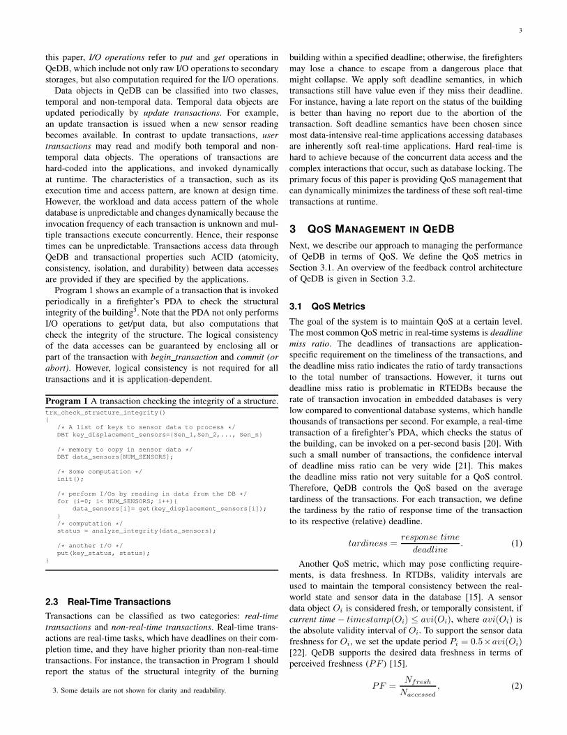
Fig. 3. The QeDB architecture.
Figure 3 shows the QoS management architecture of QeDB.
It consists of the MIMO feedback controller, QoS Man-
ager, performance monitor, transaction handler, admission
controller, and ready queue.
Admitted transactions are placed in the ready queue. Figure
3 shows three separate queues in the ready queue. Temporal
data updates are scheduled in Q0 and receive the highest
priority. Q1 handles real-time user transactions. Non-real-time
transactions in Q2 have the lowest priority, and they are
dispatched only if Q0 and Q1 are empty.
The transaction handler manages the execution of the
transactions. It consists of a freshness manager (FM), a unit
managing the concurrency control (CC), a basic scheduler
(SC), and a buffer manager (BM). Transactions in each queue
are scheduled in FCFS manner. The FM checks the freshness
of a data object before accessing it, using the timestamp
and the absolute validity interval of the data. A transaction
accessing a data object is blocked if the data object is not
fresh. For concurrency control, we apply 2PL (two phase
locking) provided by Berkeley DB which is underlying QeDB.
Transactions can be blocked, aborted, and restarted due to data
conflicts. To reduce the frequency of I/O operations, the BM
manages the cache of recently used data. This cache is shared
among the processes.
The monitor computes the I/O and CPU tardiness, i.e.,
the difference between the desired I/O (and CPU) response
time and the measured I/O (and CPU) response time at each
sampling instant. Based on the errors, the MIMO feedback
controller computes the required buffer hit ratio adjustment
(∆hit ratio) and CPU load adjustment (∆cpu load).
The QoS manager estimates the required buffer size adjust-
ment and update rate adjustment based on ∆hit ratio and
∆cpu load. Update transactions waiting in the ready queues
are discarded according to their update rates. The buffer cache
size is adapted by the BM in the transaction handler as
requested by the QoS manager.
The details of the feedback control procedure follows.
3.2.1 Feedback control procedure
Controller
(MIMO)
RTEDB
Tardiness+
−
+
−−−
−
1
1
e (k)
i/o
cpu
e (k)tardiness (k)
i/o
cpu_load
hit_ratio∆
∆ tardiness (k)cpu
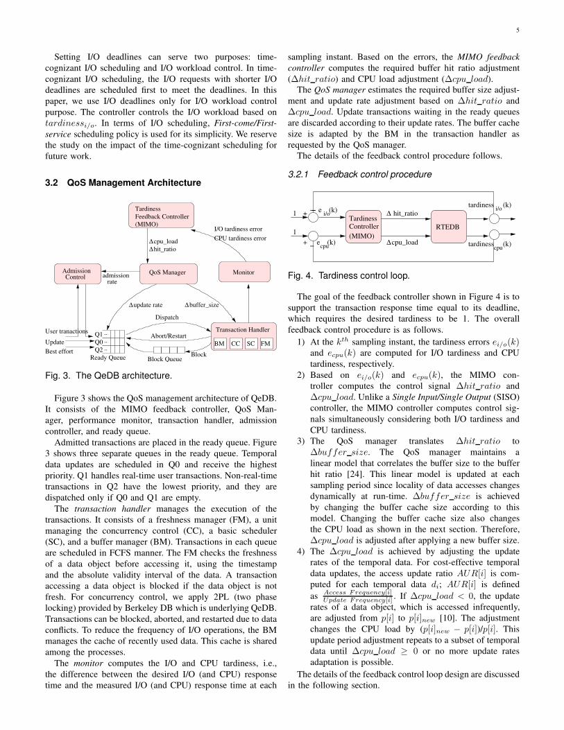
Fig. 4. Tardiness control loop.
The goal of the feedback controller shown in Figure 4 is to
support the transaction response time equal to its deadline,
which requires the desired tardiness to be 1. The overall
feedback control procedure is as follows.
1) At the kth sampling instant, the tardiness errors ei/o(k)and ecpu(k) are computed for I/O tardiness and CPU
tardiness, respectively.
2) Based on ei/o(k) and ecpu(k), the MIMO con-
troller computes the control signal ∆hit ratio and
∆cpu load. Unlike a Single Input/Single Output (SISO)
controller, the MIMO controller computes control sig-
nals simultaneously considering both I/O tardiness and
CPU tardiness.
3) The QoS manager translates ∆hit ratio to
∆buffer size. The QoS manager maintains a
linear model that correlates the buffer size to the buffer
hit ratio [24]. This linear model is updated at each
sampling period since locality of data accesses changes
dynamically at run-time. ∆buffer size is achieved
by changing the buffer cache size according to this
model. Changing the buffer cache size also changes
the CPU load as shown in the next section. Therefore,
∆cpu load is adjusted after applying a new buffer size.
4) The ∆cpu load is achieved by adjusting the update
rates of the temporal data. For cost-effective temporal
data updates, the access update ratio AUR[i] is com-
puted for each temporal data di; AUR[i] is defined
asAccess Frequency[i]Update Frequency[i] . If ∆cpu load < 0, the update
rates of a data object, which is accessed infrequently,
are adjusted from p[i] to p[i]new [10]. The adjustment
changes the CPU load by (p[i]new − p[i])/p[i]. This
update period adjustment repeats to a subset of temporal
data until ∆cpu load ≥ 0 or no more update rates
adaptation is possible.
The details of the feedback control loop design are discussed
in the following section.

6
4 FEEDBACK CONTROL LOOP DESIGN
In this section, we take a systematic approach to designing the
tardiness controller.
4.1 System Modeling and Verification
The first step in the design of a feedback control loop is
the modeling of the controlled systems [23], which in our
study are RTEDBs. One approach is to use first-principles
of the RTEDB. However, the inner workings of complex
software systems such as RTEDBs are extremely complicated.
Therefore, instead of using the first-principles, we employ
system identification technique [25]. System identification is an
empirical approach that quantifies several system parameters
and performance metrics by constructing statistical models
from the data.
4.1.1 Selection of system outputs/control inputs
As defined in Section 3, the primary QoS metric in QeDB
is transaction tardiness. Hence, we need to choose tuning
parameters, or control inputs, to dynamically control trans-
action tardiness. In selecting appropriate control inputs, two
factors should be considered [26]: (1) the parameters must
be dynamically adjustable; (2) the parameters must affect the
selected performance metrics in a meaningful way. In QeDB,
we synthetically divided the tardiness into CPU tardiness and
I/O tardiness. Since QeDB has two QoS metrics, we need at
least two control inputs to precisely control them.
Given I/O tardiness as one of the QoS metrics, we can easily
choose buffer hit ratio as the system parameter to control the
I/O tardiness. Intuitively, the higher buffer hit ratio reduces the
cost of fetching data objects from secondary storages, virtually
decreasing the average I/O response time. In QeDB, the buffer
hit ratio is controlled by adjusting the size of the buffer cache.
Regarding CPU tardiness, one available tuning parameter
that significantly affects it is the utilization of CPU. High
CPU utilization can make the response time of transactions
longer due to the high CPU contention among tasks. In
RTEDBs, the major factor that decides the CPU utilization
is the frequency of temporal data updates since the frequent
update of temporal data can significantly increases the CPU
overhead. By dropping incoming update requests, we can save
the CPU load for handling them at the cost of degrading
the freshness of temporal data. However, the lower bound
of the update frequency is determined by the application’s
requirements on data freshness as stated in Section 3.1.
4.1.2 Rationale behind MIMO control
Unlike previous work [14][15], which has single-input, single-
output (SISO) control, QeDB in this paper has multiple inputs
(hit ratio and cpu load) and multiple outputs (tardinessi/oand tardinesscpu). We may choose to use two separate SISO
models for each pair of control input and system output;
one SISO model for relating ∆hit ratio and tardinessi/o,
and another model for relating ∆cpu load and tardinesscpu.
However, if an input of a system is highly affected by
another input, then a MIMO model should be considered [26]
since having two SISO models cannot capture the interactions
between the different control inputs and system outputs.
We performed a series of experiments on a testbed to
understand the interactions between multiple control inputs
and multiple system outputs (the details of the testbed and
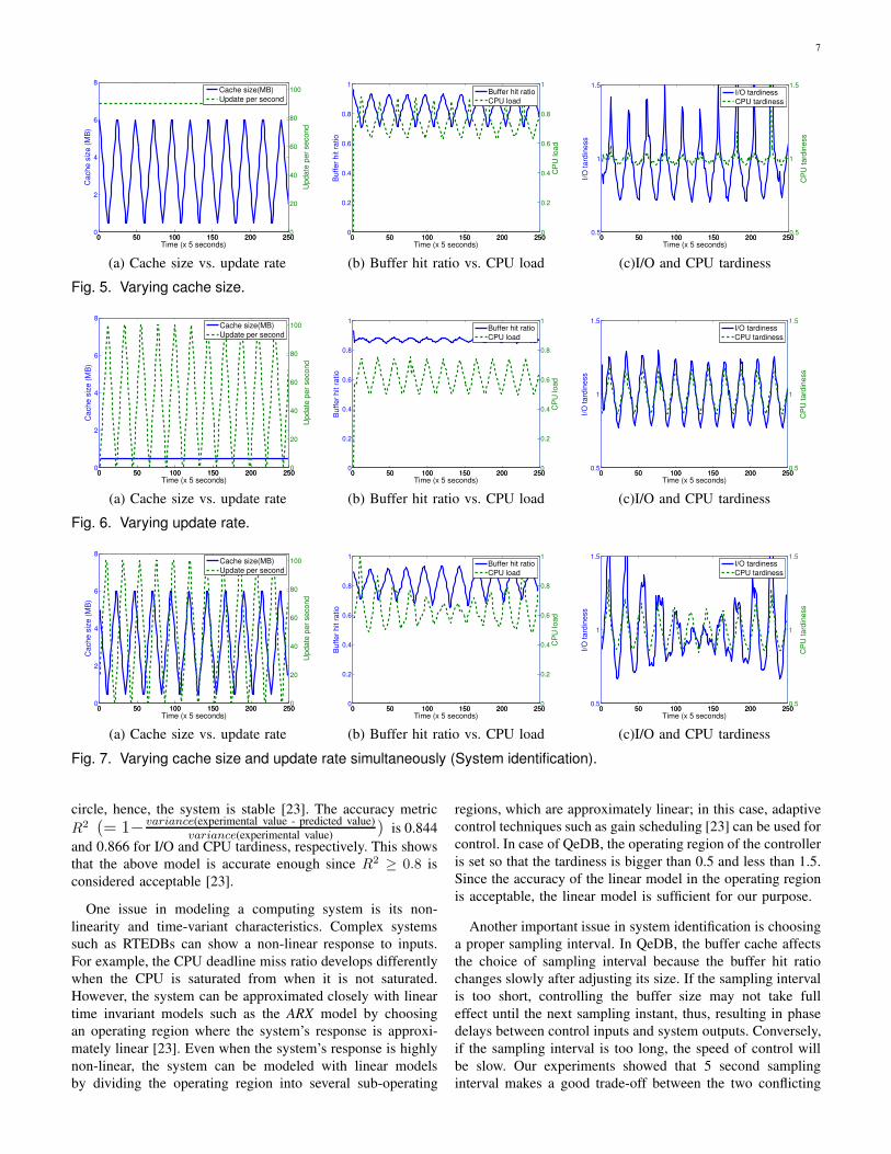
configuration parameters are discussed in Section 5.) Figure
5 shows the results of varying the cache size while the
update rate of the temporal data is fixed. It shows that
changing the buffer hit ratio via varying the cache size also
changes the CPU load, and they are inversely proportional;
increasing the buffer hit ratio decreases the CPU load, and
vice versa. This occurs because the I/O operations of QeDB
involve not only raw I/O to the secondary storage, but also
computation such as searching for data pages in a buffer,
locking data/index pages, and finding a least-recently-used
page. Therefore, when the buffer hit ratio is low, the CPU load
increases proportionally to find LRU pages, and allocate buffer
space for new pages from the secondary storage. In the next
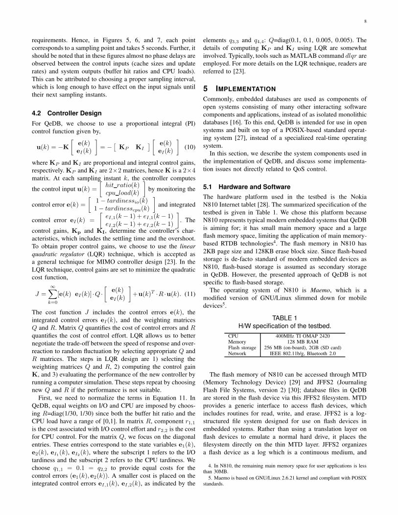
experiment, the update rate of the temporal data is varied while
the buffer size is fixed. Figure 6 shows the results. Update
transactions are computation-intensive, and they are expected
to only change the CPU load. The result in Figure 6-(b)
matches this expectation. While the buffer hit ratio is affected
a little by varying the update rates, the effect is negligible.
However, Figure 6-(c) shows that changing the CPU load
by adjusting the update rates affects both I/O tardiness and
CPU tardiness; both the I/O tardiness and the CPU tardiness
are proportional to the CPU load. This is because the I/O
operations in QeDB involves lots of computation themselves
and the increased CPU load makes them preempted more
frequently by high priority update transactions. Moreover,
increasing the update rates of the temporal data increases the
lock conflict rate, making I/O operations wait for the locks.
These results show that a MIMO model is required to capture
those close interactions of multiple inputs and multiple outputs
of QeDB.
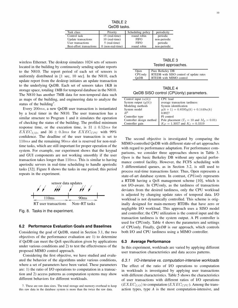
4.1.3 System identification
In the actual system identification [25] of a RTEDB, two inputs
are changed simultaneously with relatively prime cycles on
the same testbed. The relatively prime cycles are used to fully
stimulate the system by applying all different combination of
two inputs. The result, which is shown in Figure 7, is used
for system modeling.
The form of linear time invariant model for QeDB is shown
in Equation 9, with parameters A and B.[
tardinessi/o(k + 1)tardinesscpu(k + 1)
]
=
A ·
[
tardinessi/o(k)tardinesscpu(k)
]
+B ·
[
hit ratio(k)cpu load(k)
]
(9)
Because QeDB is modeled as a MIMO system, A and B
are 2x2 matrices. Note that we model QeDB as a first-order
system; the current outputs are determined by their inputs and
the outputs of the last sample. In our study, the model has
A =
[
0.275 −0.266−0.158 0.601
]
, and B =
[
−0.255 1.9800.120 0.784
]
as its parameters. All eigenvalues of A are inside the unit
7
0 50 100 150 200 2500
2
4
6
8C
ach
e s
ize
(M
B)
Time (x 5 seconds)
0 50 100 150 200 2500
20
40
60
80
100
Up
da
te p
er
se
co
nd
Cache size(MB)
Update per second
0 50 100 150 200 2500
0.2
0.4
0.6
0.8
1
Buffer
hit r
atio
Time (x 5 seconds)
0 50 100 150 200 2500
0.2
0.4
0.6
0.8
1
CP
U load
Buffer hit ratio
CPU load
0 50 100 150 200 2500.5
1
1.5
I/O
tard
iness
Time (x 5 seconds)
0 50 100 150 200 2500.5
1
1.5
CP
U tard
iness
I/O tardiness
CPU tardiness
(a) Cache size vs. update rate (b) Buffer hit ratio vs. CPU load (c)I/O and CPU tardiness
Fig. 5. Varying cache size.
0 50 100 150 200 2500
2
4
6
8
Ca
ch
e s
ize
(M
B)
Time (x 5 seconds)
0 50 100 150 200 2500
20
40
60
80
100
Up
da
te p
er
se
co
nd
Cache size(MB)
Update per second
0 50 100 150 200 2500
0.2
0.4
0.6
0.8
1
Buffer
hit r
atio
Time (x 5 seconds)
0 50 100 150 200 2500
0.2
0.4
0.6
0.8
1
CP
U load
Buffer hit ratio
CPU load
0 50 100 150 200 2500.5
1
1.5
I/O
tard
iness
Time (x 5 seconds)
0 50 100 150 200 2500.5
1
1.5
CP
U tard
iness
I/O tardiness
CPU tardiness
(a) Cache size vs. update rate (b) Buffer hit ratio vs. CPU load (c)I/O and CPU tardiness
Fig. 6. Varying update rate.
0 50 100 150 200 2500
2
4
6
8
Ca
ch
e s
ize
(M
B)
Time (x 5 seconds)
0 50 100 150 200 2500
20
40
60
80
100
Up
da
te p
er
se
co
nd
Cache size(MB)
Update per second
0 50 100 150 200 2500
0.2
0.4
0.6
0.8
1
Buffer
hit r
atio
Time (x 5 seconds)
0 50 100 150 200 2500
0.2
0.4
0.6
0.8
1C
PU
load
Buffer hit ratio
CPU load
0 50 100 150 200 2500.5
1
1.5
I/O
tard
iness
Time (x 5 seconds)
0 50 100 150 200 2500.5
1
1.5
CP
U tard
iness
I/O tardiness
CPU tardiness
(a) Cache size vs. update rate (b) Buffer hit ratio vs. CPU load (c)I/O and CPU tardiness
Fig. 7. Varying cache size and update rate simultaneously (System identification).
circle, hence, the system is stable [23]. The accuracy metric
R2 (= 1− variance(experimental value - predicted value)
variance(experimental value)) is 0.844
and 0.866 for I/O and CPU tardiness, respectively. This shows
that the above model is accurate enough since R2 ≥ 0.8 is
considered acceptable [23].
One issue in modeling a computing system is its non-
linearity and time-variant characteristics. Complex systems
such as RTEDBs can show a non-linear response to inputs.
For example, the CPU deadline miss ratio develops differently
when the CPU is saturated from when it is not saturated.
However, the system can be approximated closely with linear
time invariant models such as the ARX model by choosing
an operating region where the system’s response is approxi-
mately linear [23]. Even when the system’s response is highly
non-linear, the system can be modeled with linear models
by dividing the operating region into several sub-operating
regions, which are approximately linear; in this case, adaptive
control techniques such as gain scheduling [23] can be used for
control. In case of QeDB, the operating region of the controller
is set so that the tardiness is bigger than 0.5 and less than 1.5.
Since the accuracy of the linear model in the operating region
is acceptable, the linear model is sufficient for our purpose.
Another important issue in system identification is choosing
a proper sampling interval. In QeDB, the buffer cache affects
the choice of sampling interval because the buffer hit ratio
changes slowly after adjusting its size. If the sampling interval
is too short, controlling the buffer size may not take full
effect until the next sampling instant, thus, resulting in phase
delays between control inputs and system outputs. Conversely,
if the sampling interval is too long, the speed of control will
be slow. Our experiments showed that 5 second sampling
interval makes a good trade-off between the two conflicting
8
requirements. Hence, in Figures 5, 6, and 7, each point
corresponds to a sampling point and takes 5 seconds. Further, it
should be noted that in these figures almost no phase delays are
observed between the control inputs (cache sizes and update
rates) and system outputs (buffer hit ratios and CPU loads).
This can be attributed to choosing a proper sampling interval,
which is long enough to have effect on the input signals until
their next sampling instants.
4.2 Controller Design
For QeDB, we choose to use a proportional integral (PI)
control function given by,
u(k) = −K
[
e(k)eI(k)
]
= −[
KP KI
]
[
e(k)eI(k)
]
(10)
where KP and KI are proportional and integral control gains,
respectively. KP and KI are 2×2 matrices, hence K is a 2×4matrix. At each sampling instant k, the controller computes
the control input u(k) =
[
hit ratio(k)cpu load(k)
]
by monitoring the
control error e(k) =
[
1− tardinessio(k)1− tardinesscpu(k)
]
and integrated
control error eI(k) =
[
eI,1(k − 1) + eI,1(k − 1)eI,2(k − 1) + eI,2(k − 1)
]
. The
control gains, Kp and KI, determine the controller’s char-
acteristics, which includes the settling time and the overshoot.
To obtain proper control gains, we choose to use the linear
quadratic regulator (LQR) technique, which is accepted as
a general technique for MIMO controller design [23]. In the
LQR technique, control gains are set to minimize the quadratic
cost function,
J =
∞∑
k=0
[e(k) eI(k)] ·Q ·
[
e(k)eI(k)
]
+u(k)T ·R ·u(k). (11)
The cost function J includes the control errors e(k), the
integrated control errors eI(k), and the weighting matrices
Q and R. Matrix Q quantifies the cost of control errors and R
quantifies the cost of control effort. LQR allows us to better
negotiate the trade-off between the speed of response and over-
reaction to random fluctuation by selecting appropriate Q and
R matrices. The steps in LQR design are 1) selecting the
weighting matrices Q and R, 2) computing the control gain
K, and 3) evaluating the performance of the new controller by
running a computer simulation. These steps repeat by choosing
new Q and R if the performance is not suitable.
First, we need to normalize the terms in Equation 11. In
QeDB, equal weights on I/O and CPU are imposed by choos-
ing R=diag(1/30, 1/30) since both the buffer hit ratio and the
CPU load have a range of [0,1]. In matrix R, component r1,1is the cost associated with I/O control effort and r2,2 is the cost
for CPU control. For the matrix Q, we focus on the diagonal
entries. These entries correspond to the state variables e1(k),e2(k), eI1(k), eI2(k), where the subscript 1 refers to the I/O
tardiness and the subscript 2 refers to the CPU tardiness. We
choose q1,1 = 0.1 = q2,2 to provide equal costs for the
control errors (e1(k), e2(k)). A smaller cost is placed on the
integrated control errors eI,1(k), eI,2(k), as indicated by the
elements q3,3 and q4,4: Q=diag(0.1, 0.1, 0.005, 0.005). The
details of computing KP and KI using LQR are somewhat
involved. Typically, tools such as MATLAB command dlqr are
employed. For more details on the LQR technique, readers are
referred to [23].
5 IMPLEMENTATION
Commonly, embedded databases are used as components of
open systems consisting of many other interacting software
components and applications, instead of as isolated monolithic
databases [16]. To this end, QeDB is intended for use in open
systems and built on top of a POSIX-based standard operat-
ing system [27], instead of a specialized real-time operating
system.
In this section, we describe the system components used in
the implementation of QeDB, and discuss some implementa-
tion issues not directly related to QoS control.
5.1 Hardware and Software
The hardware platform used in the testbed is the Nokia
N810 Internet tablet [28]. The summarized specification of the
testbed is given in Table 1. We chose this platform because
N810 represents typical modern embedded systems that QeDB
is aiming for; it has small main memory space and a large
flash memory space, limiting the application of main memory-
based RTDB technologies4. The flash memory in N810 has
2KB page size and 128KB erase block size. Since flash-based
storage is de-facto standard of modern embedded devices as
N810, flash-based storage is assumed as secondary storage
in QeDB. However, the presented approach of QeDB is not
specific to flash-based storage.
The operating system of N810 is Maemo, which is a
modified version of GNU/Linux slimmed down for mobile
devices5.
TABLE 1
H/W specification of the testbed.
CPU 400MHz TI OMAP 2420Memory 128 MB RAMFlash storage 256 MB (on-board), 2GB (SD card)Network IEEE 802.11b/g, Bluetooth 2.0
The flash memory of N810 can be accessed through MTD
(Memory Technology Device) [29] and JFFS2 (Journaling
Flash File Systems, version 2) [30]; database files in QeDB
are stored in the flash device via this JFFS2 filesystem. MTD
provides a generic interface to access flash devices, which
includes routines for read, write, and erase. JFFS2 is a log-
structured file system designed for use on flash devices in
embedded systems. Rather than using a translation layer on
flash devices to emulate a normal hard drive, it places the
filesystem directly on the thin MTD layer. JFFS2 organizes
a flash device as a log which is a continuous medium, and
4. In N810, the remaining main memory space for user applications is lessthan 30MB.
5. Maemo is based on GNU/Linux 2.6.21 kernel and compliant with POSIXstandards.

9
data is always written to the end of the log. In a flash device
old data cannot be overwritten before erasing, so the modified
data must be written out-of-place. Using a background process,
JFFS2 collects garbage data.
QeDB is an extension of Berkeley DB, which is a popular
open-source embedded database. Berkeley DB provides robust
storage features as found in traditional database systems, such
as ACID transactions, recovery, locking, multi-threading for
concurrency, and slave-master replication for high availability.
However, Berkeley DB does not provide the QoS support in
terms of transaction tardiness and data freshness, which is the
main objective for the design of QeDB.
5.2 Implementation Details and Issues
We discuss several implementation issues and challenges for
implementing QeDB.
5.2.1 CPU scheduling
Currently, Linux underlying QeDB supports preemptive real-
time scheduling by partially implementing POSIX 1003.b
and 1003.c real-time extension features [18][27]6. Since the
POSIX real-time extension does not support optimal real-
time scheduling and concurrency control algorithms such as
EDF (earliest-deadline-first), they should be implemented in
RTEDBs for optimal performance. However, we choose to
assign priorities manually to tasks based on their importance,
since the experimental results in [31] show that static priority
assignment schemes achieve the performance very close to that
of EDF when the multi-programming level (MPL) is low; the
MPL of real-time tasks in QeDB is typically less than 3.
Four classes of tasks or transactions are defined in QeDB.
Different priorities are assigned to them based on their im-
portance as shown in Table 2. First, the control task, which
periodically performs monitoring and feedback control of the
system, is assigned the highest priority, 15. On every sampling
period, the control task calculates and enforces the control in-
puts by adjusting system parameters, and then sleeps until the
next sampling period starts. Update transactions are aperiodic
real-time tasks with priority 10 and they are invoked when
new updates of temporal data arrives. Update transactions are
scheduled by FIFO scheduling policy. We assign priority 5to user transactions, since delayed sensor data updates can
impair the freshness of data. Finally, the priority of best-effort
transactions is 0, which is a non-real-time priority.
5.2.2 CPU load measurement
The CPU load is one of the control inputs in QeDB, and the
effectiveness of feedback control depends on the preciseness of
the CPU load information. In Linux underlying QeDB, several
types of CPU information are available for users and applica-
tions. First, Linux exports CPU load average information via
proc file system (/proc/loadavg), and several commands like
top use this information. However, this information is based
on queuing-theoretic estimation by observing the length of run
6. In POSIX threads, fixed priorities, ranging from 1 to 99, belong to real-time scheduling class and their priority is not dynamically adjusted by theCPU scheduler.
queue in the CPU scheduler. Moreover, this does not provide
fine-grained information on how much CPU time has been
used by a specific set of tasks. Instead of using this CPU
load average information, we use the number of clock ticks
that have actually been used by the real-time tasks both in
user and kernel modes. This information is available via the
/proc/stat interface in Linux. It should be noted that when we
measure the CPU load, we only consider the CPU time spent
by real-time tasks, since the load incurred by non-real-time
tasks does not affect the tardiness of the real-time tasks. The
CPU time is assigned to non-real-time tasks only when there
is no real-time task. Hence, the CPU load at each sampling
period for control purpose is measured as follows:
time spent by real-time tasks in the sampling period
sampling period. (12)
5.2.3 Avoiding double buffering
QeDB uses a file system to store data. When using file systems
with a database, the read data is double-buffered in both the
file system buffer cache and the DBMS buffer cache. Double
buffering not only wastes memory space, but also makes I/O
response time unpredictable. DBMS have no control over the
filesystem layer buffer cache, since it is controlled by the
operating system. QeDB’s dynamic buffer adjustment scheme
cannot achieve its goal in the presence of double-buffer since
changing the buffer size at QeDB only affects the buffer in the
DBMS layer. Unfortunately, Berkeley DB for Linux, which is
underlying QeDB, does not support direct I/O, or bypassing
the file system’s buffer cache. QeDB solves this problem by
making a separate partition for database files, and disabling the
buffer cache of that partition at the file system level. The buffer
cache in the file system is disabled by applying modification
to the JFFS2 code in the Linux kernel.
6 EVALUATION
In this section, we discuss the goal and background of the
experiments and present the results.
6.1 Evaluation Testbed
Firefighting has been considered as one of the domains that
can best benefit from improvements in timely sensor data
gathering, processing and integration. Little timely information
can make huge differences in making decisions [20][5][6]. If
we can build a system that satisfies the requirements of such a
highly stressful domain, we might also be able to apply these
results in less extreme environments, such as computing while
driving. To this end, a firefighting scenario from [6] is adopted,
and simulated on our testbed for more realistic evaluation.
In the scenario, a PDA carried by a firefighter collects sensor
data via wireless communication, and a periodic real-time
task running on the PDA checks the status of the burning
building such as the possibility of collapse, explosion, the
existence of safe retreat path, etc. The PDA carried by a
firefighter is simulated by a N810 Internet tablet and a stream
of sensor data from a building is simulated by a separate
3.0 GHz Linux desktop. The two devices are connected via
10
TABLE 2QeDB tasks.
Task class Priority Scheduling policy periodicity
Control task 15 (real-time) round robin periodicUpdate transactions 10 (real-time) FIFO non-periodicUser transactions 5 (real-time) FIFO periodicBest-effort transactions 0 (non-real-time) round robin non-periodic
wireless Ethernet. The desktop simulates 1024 sets of sensors
located in the building by continuously sending update reports
to the N810. The report period of each set of sensors is
uniformly distributed in [1 sec, 10 sec]. In the N810, each
update report from the desktop initiates an update transaction
to the underlying QeDB. Each set of sensors takes 1KB in
storage space, totaling 1MB for temporal database in the N810.
The N810 has another 7MB data for non-temporal data such
as maps of the building, and engineering data to analyze the
status of the building7.
Every 200ms, a new QeDB user transaction is instantiated
by a local timer in the N810. The user transaction has a
similar structure to Program 1 and it simulates the operation
of checking the status of the building. The profiled minimum
response time, or the execution time, is 31 ± 0.52ms for
EXECI/O, and 36 ± 0.3ms for EXECCPU with 99%
confidence. The deadline of the user transaction is set to
110ms and the remaining 90ms slot is reserved for non-real-
time tasks, which are still important for proper operation of the
system. For example, our experiment shows that the keypad
and GUI components are not working smoothly if the user
transaction takes longer than 110ms. This is similar to having
aperiodic servers in real-time scheduling to handle aperiodic
tasks [32]. Figure 8 shows the tasks in one period; this period
repeats in the experiment.
sensor data updates
90ms
RT user transactions Non−RT tasks
110ms
Fig. 8. Tasks in the experiment.
6.2 Performance Evaluation Goals and Baselines
Considering the goal of QeDB, stated in Section 3.1, the two
objectives of the performance evaluation are 1) to determine
if QeDB can meet the QoS specification given by applications
under various conditions and 2) to test the effectiveness of the
proposed MIMO control approach.
Considering the first objective, we have studied and evalu-
ated the behavior of the algorithms under various conditions,
where a set of parameters have been varied. These parameters
are: 1) the ratio of I/O operations to computation in a transac-
tion and 2) access patterns as computation systems may show
different behaviors for different workloads.
7. These are raw data sizes. The total storage and memory overhead to keepthis raw data in the database system is more than the twice the raw data.
TABLE 3Tested approaches.
Open Pure Berkeley DBCPUonly RTEDB with SISO control of update ratesQeDB RTEDB with MIMO control
TABLE 4QeDB SISO control (CPUonly) parameters.
Control input (u(k)) CPU loadSystem output (y(k)) average transaction tardinessModeling methods System identificationSystem model y(k + 1) = 0.8595y(k) + 0.1449u(k)R2 0.8927Controller type PI controlController design method Pole placement (Ts = 10 and Mp = 0.01)Controller gain KP = 1.3057 and KI = 0.3319
The second objective is investigated by comparing the
MIMO-controlled QeDB with different state-of-art approaches
with regard to performance adaptation. For performance com-
parisons, we consider three approaches shown in Table 3.
Open is the basic Berkeley DB without any special perfor-
mance control facility. However, the FCFS scheduling with
3 differentiated queues, as in Section 3.2, is still used to
process real-time transactions faster. Thus, Open represents a
state-of-art database system. In contrast, CPUonly represents
a RTDB having a QoS management scheme [10], which is
not I/O-aware. In CPUonly, as the tardiness of transactions
deviates from the desired tardiness, only the CPU workload
is adjusted by changing update rates of temporal data. I/O
workload is not dynamically controlled. This scheme is orig-
inally designed for main-memory RTDBs that have zero or
negligible I/O workload. This approach uses a SISO model
and controller; the CPU utilization is the control input and the
transaction tardiness is the system output. A PI controller is
used for CPUonly. Table 4 shows the parameters and settings
of CPUonly. Finally, QeDB is our approach, which controls
both I/O and CPU tardiness using a MIMO controller.
6.3 Average Performance
In this experiment, workloads are varied by applying different
user transaction characteristics and data access patterns.
6.3.1 I/O-intensive vs. computation-intensive workloads
The effect of the ratio of I/O operations to computation
in workloads is investigated by applying user transactions
with different characteristics. Table 5 shows the characteristics
of user transactions with different ratios of I/O operations
(EXECI/O) to computation (EXECCPU ). Among the trans-
action types, type A is the most computation-intensive, and
11
A B C D E0
0.2
0.4
0.6
0.8
1
1.2
1.4
1.6
1.8
2T
ard
iness
Open
CPUonly
QeDB
A B C D E0
0.1
0.2
0.3
0.4
0.5
0.6
0.7
0.8
0.9
1
Perc
eiv
ed fre
shness
Open
CPUonly
QeDB
A B C D E0
1
2
3
4
5
6
Bu
ffe
r siz
e(M
B)
Open
CPUonly
QeDB
(a) Tardiness (b) Perceived freshness (c) Buffer size
Fig. 9. Average performance with different I/O-to-computation ratios.
TABLE 5
User transaction properties.
Type EXECI/O EXECCPU
A 15ms 53msB 27ms 39msC 35ms 33msD 45ms 23msE 55ms 13ms
conversely type E is the most I/O-intensive. The minimum
I/O execution time, EXECI/O, is adjusted by changing the
number of data object accesses per user transaction. Similarly,
the minimum computation time, EXECCPU , is adjusted by
changing the loop counts of a dummy computation loop.
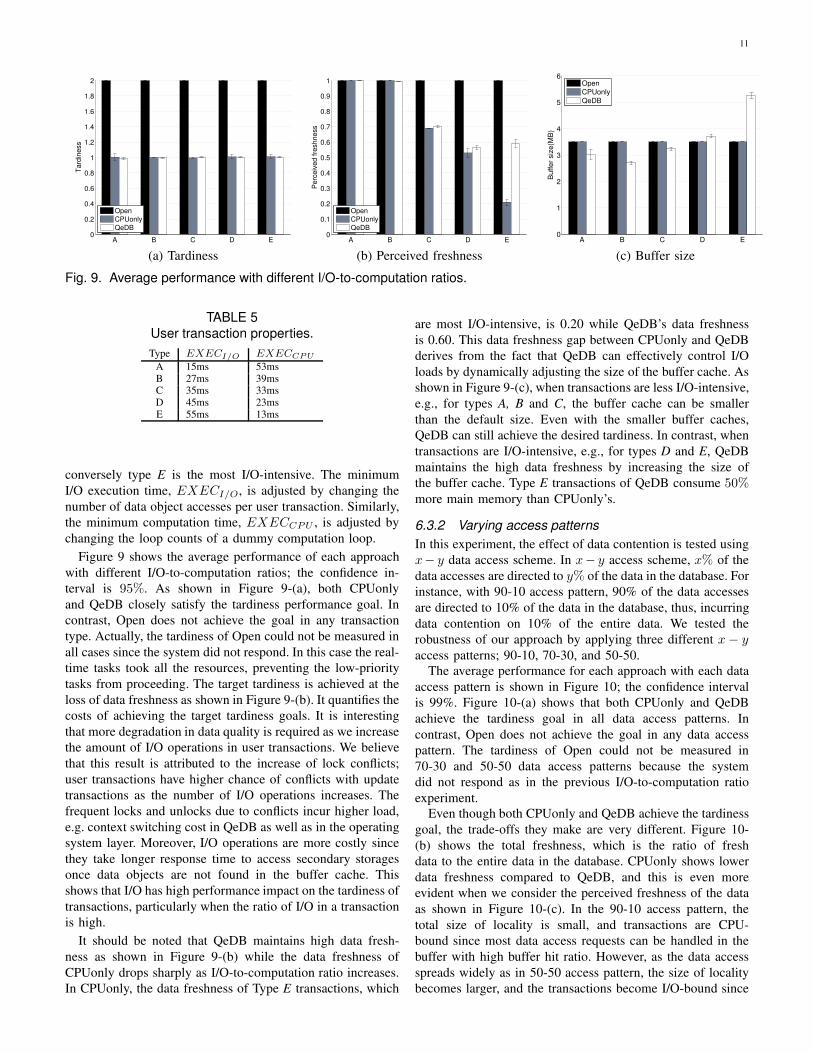
Figure 9 shows the average performance of each approach
with different I/O-to-computation ratios; the confidence in-
terval is 95%. As shown in Figure 9-(a), both CPUonly
and QeDB closely satisfy the tardiness performance goal. In
contrast, Open does not achieve the goal in any transaction
type. Actually, the tardiness of Open could not be measured in
all cases since the system did not respond. In this case the real-
time tasks took all the resources, preventing the low-priority
tasks from proceeding. The target tardiness is achieved at the
loss of data freshness as shown in Figure 9-(b). It quantifies the
costs of achieving the target tardiness goals. It is interesting
that more degradation in data quality is required as we increase
the amount of I/O operations in user transactions. We believe
that this result is attributed to the increase of lock conflicts;
user transactions have higher chance of conflicts with update
transactions as the number of I/O operations increases. The
frequent locks and unlocks due to conflicts incur higher load,
e.g. context switching cost in QeDB as well as in the operating
system layer. Moreover, I/O operations are more costly since
they take longer response time to access secondary storages
once data objects are not found in the buffer cache. This
shows that I/O has high performance impact on the tardiness of
transactions, particularly when the ratio of I/O in a transaction
is high.
It should be noted that QeDB maintains high data fresh-
ness as shown in Figure 9-(b) while the data freshness of
CPUonly drops sharply as I/O-to-computation ratio increases.
In CPUonly, the data freshness of Type E transactions, which
are most I/O-intensive, is 0.20 while QeDB’s data freshness
is 0.60. This data freshness gap between CPUonly and QeDB
derives from the fact that QeDB can effectively control I/O
loads by dynamically adjusting the size of the buffer cache. As
shown in Figure 9-(c), when transactions are less I/O-intensive,
e.g., for types A, B and C, the buffer cache can be smaller
than the default size. Even with the smaller buffer caches,
QeDB can still achieve the desired tardiness. In contrast, when
transactions are I/O-intensive, e.g., for types D and E, QeDB
maintains the high data freshness by increasing the size of
the buffer cache. Type E transactions of QeDB consume 50%more main memory than CPUonly’s.
6.3.2 Varying access patterns
In this experiment, the effect of data contention is tested using
x− y data access scheme. In x− y access scheme, x% of the
data accesses are directed to y% of the data in the database. For
instance, with 90-10 access pattern, 90% of the data accesses
are directed to 10% of the data in the database, thus, incurring
data contention on 10% of the entire data. We tested the
robustness of our approach by applying three different x− y
access patterns; 90-10, 70-30, and 50-50.
The average performance for each approach with each data
access pattern is shown in Figure 10; the confidence interval
is 99%. Figure 10-(a) shows that both CPUonly and QeDB
achieve the tardiness goal in all data access patterns. In
contrast, Open does not achieve the goal in any data access
pattern. The tardiness of Open could not be measured in
70-30 and 50-50 data access patterns because the system
did not respond as in the previous I/O-to-computation ratio
experiment.
Even though both CPUonly and QeDB achieve the tardiness
goal, the trade-offs they make are very different. Figure 10-
(b) shows the total freshness, which is the ratio of fresh
data to the entire data in the database. CPUonly shows lower
data freshness compared to QeDB, and this is even more
evident when we consider the perceived freshness of the data
as shown in Figure 10-(c). In the 90-10 access pattern, the
total size of locality is small, and transactions are CPU-
bound since most data access requests can be handled in the
buffer with high buffer hit ratio. However, as the data access
spreads widely as in 50-50 access pattern, the size of locality
becomes larger, and the transactions become I/O-bound since

12
90−10 70−30 50−500
0.5
1
1.5
2
2.5
3
3.5
4
Ta
rdin
ess
Open
CPUonly
QeDB
90−10 70−30 50−500
0.1
0.2
0.3
0.4
0.5
0.6
0.7
0.8
0.9
1
To
tal fr
esh
ne
ss
Open
CPUonly
QeDB
(a) Tardiness (b) Total freshness
90−10 70−30 50−500
0.1
0.2
0.3
0.4
0.5
0.6
0.7
0.8
0.9
1
Pe
rce
ive
d f
resh
ne
ss
Open
CPUonly
QeDB
90−10 70−30 50−500
1
2
3
4
5
6
Bu
ffe
r siz
e(M
B)
Open
CPUonly
QeDB
(c) Perceived freshness (d) Buffer size
Fig. 10. Average performance with X-Y access patterns.
the small buffer of CPUonly incurs low hit ratio. In the
CPUonly case, the tardiness is controlled only by adjusting the
freshness of the temporal data, regardless of which resource
is getting overloaded. Therefore, CPUonly has to lower the
freshness of the data excessively, which can be problematic
if an application requires high data freshness. For example,
the total freshness of CPUonly drops from 0.73 ± 0.02 to
0.37± 0.1 when the access pattern changes from 90-10 to 50-
50, which is more than 50% degradation of the data freshness.
In contrast, QeDB achieves more stable data freshness in all
data access patterns. As the size of locality is getting larger,
QeDB increases the size of the buffer as in Figure 10-(d),
while still maintaining high data freshness. For instance, the
buffer size increase about 64% and the total freshness drops
18% when the access pattern changes from 90-10 to 50-50. If
we consider the perceived freshness of the data, the difference
between CPUonly and QeDB is even higher. The perceived
freshness drops only 14% in QeDB while it drops 40% in
CPUonly.
6.4 Transient Performance
The average performance is not enough to show the perfor-
mance of dynamic systems. Transient performance such as set-
tling time should be small enough to satisfy the requirements
of applications. In this experiment, the workload increases
by introducing a disturbance. For example, consider a situ-
ation where peer firefighters opportunistically exchange their
temporal data when they are close enough to communicate
with each other. This opportunistic data exchange incurs both
additional I/O and CPU load to process it. In the experiment,
the disturbance is a periodic transaction that lasts for 50
sampling periods. The periodic transaction retrieves 1KB data
page with 10ms interval.
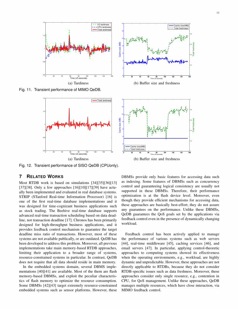
Figure 11-(a) shows the tardiness of real-time transactions.
The corresponding buffer hit ratio and data freshness at the
same time are shown in Figure 11-(b). The disturbance starts
at the 60th sampling period and ends at the 110th sampling
period. In Figure 11-(a), we can see that the tardiness increases
suddenly at the 60th sampling period. However, the tardiness
stabilizes within 3 sampling periods. When the disturbance
disappears at the 110th sampling period, it takes 8 sampling
periods to stabilize. These long settling times are the result
of controller tuning in the controller design phase in Section
4.2. We could reduce the settling times by choosing control
parameters for more aggressive control at the controller de-
sign time. However, aggressive control results in the higher
overshoot and fluctuations in controller inputs (the cache size
and update rates). For details on controller tuning, the reader
is referred to [33]
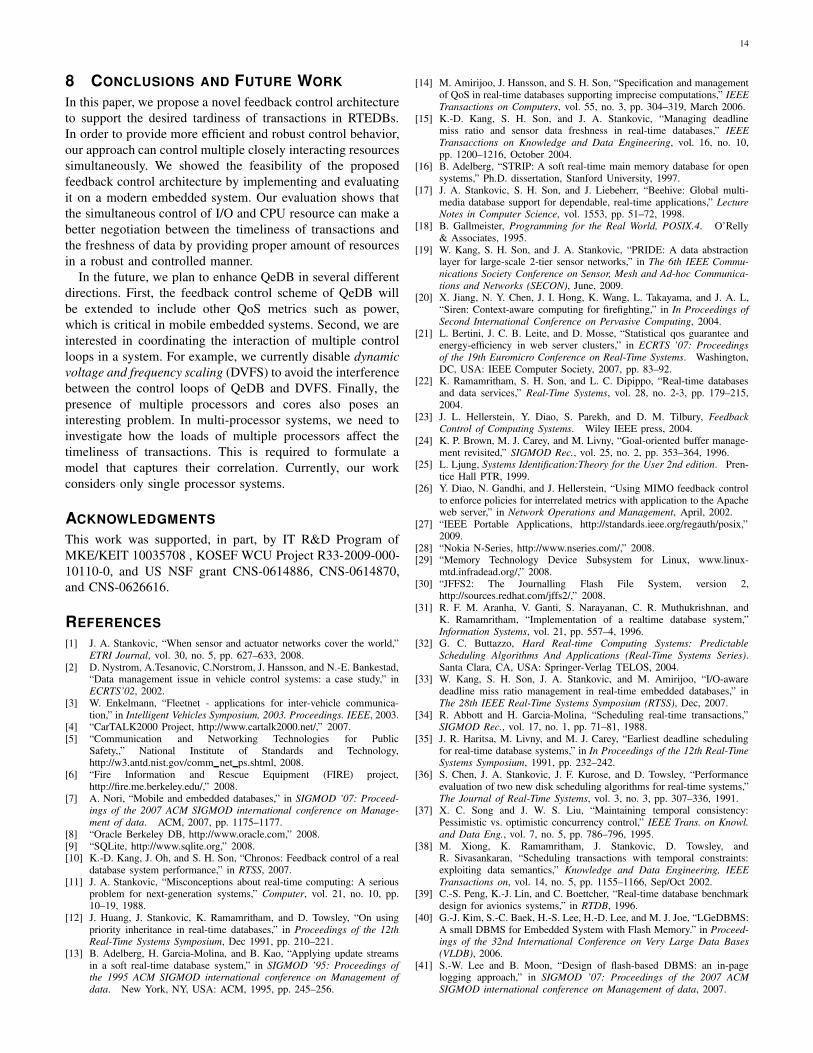
Figure 12 shows the transient behavior of CPUonly in
the same experiment settings. In coping with the unexpected
disturbance, CPUonly exhibits similar transient behavior as
QeDB in terms of the settling time and overshoot (see Figure
12-(a)). However, CPUonly makes greater tradeoffs in data
freshness to guarantee the desired tardiness as shown in Figure
12-(b). Hence, the data freshness of CPUonly fluctuates highly.
The fluctuation magnitudes are 64% and 39%, respectively for
CPUonly and QeDB.
13
0 20 40 60 80 100 120 140 1600.6
0.8
1
1.2
1.4
Time (x5 seconds)
I/O tardiness
CPU tardiness
Total tardiness
0 20 40 60 80 100 120 140 1600
2
4
6
8
10
12
14
Cache s
ize (
MB
)
Time (x5 seconds)
0 20 40 60 80 100 120 140 1600
0.2
0.4
0.6
0.8
1
Tota
l fr
eshness
Cache size(MB)
Total freshness
(a) Tardiness (b) Buffer size and freshness
Fig. 11. Transient performance of MIMO QeDB.
0 20 40 60 80 100 120 140 1600.6
0.8
1
1.2
1.4
Time (x5 seconds)
Total tardiness
0 20 40 60 80 100 120 140 1600
2
4
6
8
10
12
14
Cache s
ize (
MB
)
Time (x5 seconds)
0 20 40 60 80 100 120 140 1600
0.2
0.4
0.6
0.8
1
Tota
l fr
eshness
Cache size(MB)
Total freshness
(a) Tardiness (b) Buffer size and freshness
Fig. 12. Transient performance of SISO QeDB (CPUonly).
7 RELATED WORKS
Most RTDB work is based on simulations [34][35][36][13]
[37][38]. Only a few approaches [16][10][17][39] have actu-
ally been implemented and evaluated in real database systems.
STRIP (STanford Real-time Information Processor) [16] is
one of the first real-time database implementations and it
was designed for time-cognizant business applications such
as stock trading. The Beehive real-time database supports
advanced real-time transaction scheduling based on data dead-
line, not transaction deadline [17]. Chronos has been primarily
designed for high-throughput business applications, and it
provides feedback control mechanism to guarantee the target
deadline miss ratio of transactions. However, most of these
systems are not available publically, or are outdated. QeDB has
been developed to address this problem. Moreover, all previous
implementations take main memory-based RTDB approaches,
limiting their application to a broader range of systems,
resource-constrained systems in particular. In contrast, QeDB
does not require that all data should reside in main memory.
In the embedded systems domain, several DBMS imple-
mentations [40][41] are available. Most of the them are flash
memory-based DBMSs, and exploit the peculiar characteris-
tics of flash memory to optimize the resource consumption.
Some DBMSs [42][43] target extremely resource-constrained
embedded systems such as sensor platforms. However, these
DBMSs provide only basic features for accessing data such
as indexing. Some features of DBMSs such as concurrency
control and guaranteeing logical consistency are usually not
supported in these DBMSs. Therefore, their performance
optimization is at the flash device level. Moreover, even
though they provide efficient mechanisms for accessing data,
these approaches are basically best-effort; they do not assure
any guarantees on the performance. Unlike these DBMSs,
QeDB guarantees the QoS goals set by the applications via
feedback control even in the presence of dynamically changing
workload.
Feedback control has been actively applied to manage
the performance of various systems such as web servers
[44], real-time middleware [45], caching services [46], and
email servers [47]. In particular, applying control-theoretic
approaches to computing systems showed its effectiveness
when the operating environments, e.g., workload, are highly
dynamic and unpredictable. However, these approaches are not
directly applicable to RTDBs, because they do not consider
RTDB-specific issues such as data freshness. Moreover, these
approaches consider only single resource, e.g., contention in
CPU, for QoS management. Unlike these approaches, QeDB
manages multiple resources, which have close interaction, via
MIMO feedback control.
14
8 CONCLUSIONS AND FUTURE WORK
In this paper, we propose a novel feedback control architecture
to support the desired tardiness of transactions in RTEDBs.
In order to provide more efficient and robust control behavior,
our approach can control multiple closely interacting resources
simultaneously. We showed the feasibility of the proposed
feedback control architecture by implementing and evaluating
it on a modern embedded system. Our evaluation shows that
the simultaneous control of I/O and CPU resource can make a
better negotiation between the timeliness of transactions and
the freshness of data by providing proper amount of resources
in a robust and controlled manner.
In the future, we plan to enhance QeDB in several different
directions. First, the feedback control scheme of QeDB will
be extended to include other QoS metrics such as power,
which is critical in mobile embedded systems. Second, we are
interested in coordinating the interaction of multiple control
loops in a system. For example, we currently disable dynamic
voltage and frequency scaling (DVFS) to avoid the interference
between the control loops of QeDB and DVFS. Finally, the
presence of multiple processors and cores also poses an
interesting problem. In multi-processor systems, we need to
investigate how the loads of multiple processors affect the
timeliness of transactions. This is required to formulate a
model that captures their correlation. Currently, our work
considers only single processor systems.
ACKNOWLEDGMENTS
This work was supported, in part, by IT R&D Program of
MKE/KEIT 10035708 , KOSEF WCU Project R33-2009-000-
10110-0, and US NSF grant CNS-0614886, CNS-0614870,
and CNS-0626616.
REFERENCES
[1] J. A. Stankovic, “When sensor and actuator networks cover the world,”ETRI Journal, vol. 30, no. 5, pp. 627–633, 2008.
[2] D. Nystrom, A.Tesanovic, C.Norstrom, J. Hansson, and N.-E. Bankestad,“Data management issue in vehicle control systems: a case study,” inECRTS’02, 2002.
[3] W. Enkelmann, “Fleetnet - applications for inter-vehicle communica-tion,” in Intelligent Vehicles Symposium, 2003. Proceedings. IEEE, 2003.
[4] “CarTALK2000 Project, http://www.cartalk2000.net/,” 2007.[5] “Communication and Networking Technologies for Public
Safety,,” National Institute of Standards and Technology,http://w3.antd.nist.gov/comm net ps.shtml, 2008.
[6] “Fire Information and Rescue Equipment (FIRE) project,http://fire.me.berkeley.edu/,” 2008.
[7] A. Nori, “Mobile and embedded databases,” in SIGMOD ’07: Proceed-ings of the 2007 ACM SIGMOD international conference on Manage-
ment of data. ACM, 2007, pp. 1175–1177.[8] “Oracle Berkeley DB, http://www.oracle.com,” 2008.[9] “SQLite, http://www.sqlite.org,” 2008.[10] K.-D. Kang, J. Oh, and S. H. Son, “Chronos: Feedback control of a real
database system performance,” in RTSS, 2007.[11] J. A. Stankovic, “Misconceptions about real-time computing: A serious
problem for next-generation systems,” Computer, vol. 21, no. 10, pp.10–19, 1988.
[12] J. Huang, J. Stankovic, K. Ramamritham, and D. Towsley, “On usingpriority inheritance in real-time databases,” in Proceedings of the 12thReal-Time Systems Symposium, Dec 1991, pp. 210–221.
[13] B. Adelberg, H. Garcia-Molina, and B. Kao, “Applying update streamsin a soft real-time database system,” in SIGMOD ’95: Proceedings ofthe 1995 ACM SIGMOD international conference on Management of
data. New York, NY, USA: ACM, 1995, pp. 245–256.
[14] M. Amirijoo, J. Hansson, and S. H. Son, “Specification and managementof QoS in real-time databases supporting imprecise computations,” IEEE
Transactions on Computers, vol. 55, no. 3, pp. 304–319, March 2006.[15] K.-D. Kang, S. H. Son, and J. A. Stankovic, “Managing deadline
miss ratio and sensor data freshness in real-time databases,” IEEE
Transacctions on Knowledge and Data Engineering, vol. 16, no. 10,pp. 1200–1216, October 2004.
[16] B. Adelberg, “STRIP: A soft real-time main memory database for opensystems,” Ph.D. dissertation, Stanford University, 1997.
[17] J. A. Stankovic, S. H. Son, and J. Liebeherr, “Beehive: Global multi-media database support for dependable, real-time applications,” LectureNotes in Computer Science, vol. 1553, pp. 51–72, 1998.
[18] B. Gallmeister, Programming for the Real World, POSIX.4. O’Relly& Associates, 1995.
[19] W. Kang, S. H. Son, and J. A. Stankovic, “PRIDE: A data abstractionlayer for large-scale 2-tier sensor networks,” in The 6th IEEE Commu-
nications Society Conference on Sensor, Mesh and Ad-hoc Communica-
tions and Networks (SECON), June, 2009.[20] X. Jiang, N. Y. Chen, J. I. Hong, K. Wang, L. Takayama, and J. A. L,
“Siren: Context-aware computing for firefighting,” in In Proceedings of
Second International Conference on Pervasive Computing, 2004.[21] L. Bertini, J. C. B. Leite, and D. Mosse, “Statistical qos guarantee and
energy-efficiency in web server clusters,” in ECRTS ’07: Proceedings
of the 19th Euromicro Conference on Real-Time Systems. Washington,DC, USA: IEEE Computer Society, 2007, pp. 83–92.
[22] K. Ramamritham, S. H. Son, and L. C. Dipippo, “Real-time databasesand data services,” Real-Time Systems, vol. 28, no. 2-3, pp. 179–215,2004.
[23] J. L. Hellerstein, Y. Diao, S. Parekh, and D. M. Tilbury, FeedbackControl of Computing Systems. Wiley IEEE press, 2004.
[24] K. P. Brown, M. J. Carey, and M. Livny, “Goal-oriented buffer manage-ment revisited,” SIGMOD Rec., vol. 25, no. 2, pp. 353–364, 1996.
[25] L. Ljung, Systems Identification:Theory for the User 2nd edition. Pren-tice Hall PTR, 1999.
[26] Y. Diao, N. Gandhi, and J. Hellerstein, “Using MIMO feedback controlto enforce policies for interrelated metrics with application to the Apacheweb server,” in Network Operations and Management, April, 2002.
[27] “IEEE Portable Applications, http://standards.ieee.org/regauth/posix,”2009.
[28] “Nokia N-Series, http://www.nseries.com/,” 2008.[29] “Memory Technology Device Subsystem for Linux, www.linux-
mtd.infradead.org/,” 2008.[30] “JFFS2: The Journalling Flash File System, version 2,
http://sources.redhat.com/jffs2/,” 2008.[31] R. F. M. Aranha, V. Ganti, S. Narayanan, C. R. Muthukrishnan, and
K. Ramamritham, “Implementation of a realtime database system,”Information Systems, vol. 21, pp. 557–4, 1996.
[32] G. C. Buttazzo, Hard Real-time Computing Systems: Predictable
Scheduling Algorithms And Applications (Real-Time Systems Series).Santa Clara, CA, USA: Springer-Verlag TELOS, 2004.
[33] W. Kang, S. H. Son, J. A. Stankovic, and M. Amirijoo, “I/O-awaredeadline miss ratio management in real-time embedded databases,” inThe 28th IEEE Real-Time Systems Symposium (RTSS), Dec, 2007.
[34] R. Abbott and H. Garcia-Molina, “Scheduling real-time transactions,”SIGMOD Rec., vol. 17, no. 1, pp. 71–81, 1988.
[35] J. R. Haritsa, M. Livny, and M. J. Carey, “Earliest deadline schedulingfor real-time database systems,” in In Proceedings of the 12th Real-TimeSystems Symposium, 1991, pp. 232–242.
[36] S. Chen, J. A. Stankovic, J. F. Kurose, and D. Towsley, “Performanceevaluation of two new disk scheduling algorithms for real-time systems,”The Journal of Real-Time Systems, vol. 3, no. 3, pp. 307–336, 1991.
[37] X. C. Song and J. W. S. Liu, “Maintaining temporal consistency:Pessimistic vs. optimistic concurrency control,” IEEE Trans. on Knowl.
and Data Eng., vol. 7, no. 5, pp. 786–796, 1995.[38] M. Xiong, K. Ramamritham, J. Stankovic, D. Towsley, and
R. Sivasankaran, “Scheduling transactions with temporal constraints:exploiting data semantics,” Knowledge and Data Engineering, IEEE
Transactions on, vol. 14, no. 5, pp. 1155–1166, Sep/Oct 2002.[39] C.-S. Peng, K.-J. Lin, and C. Boettcher, “Real-time database benchmark
design for avionics systems,” in RTDB, 1996.[40] G.-J. Kim, S.-C. Baek, H.-S. Lee, H.-D. Lee, and M. J. Joe, “LGeDBMS:
A small DBMS for Embedded System with Flash Memory.” in Proceed-ings of the 32nd International Conference on Very Large Data Bases
(VLDB), 2006.[41] S.-W. Lee and B. Moon, “Design of flash-based DBMS: an in-page
logging approach,” in SIGMOD ’07: Proceedings of the 2007 ACM
SIGMOD international conference on Management of data, 2007.
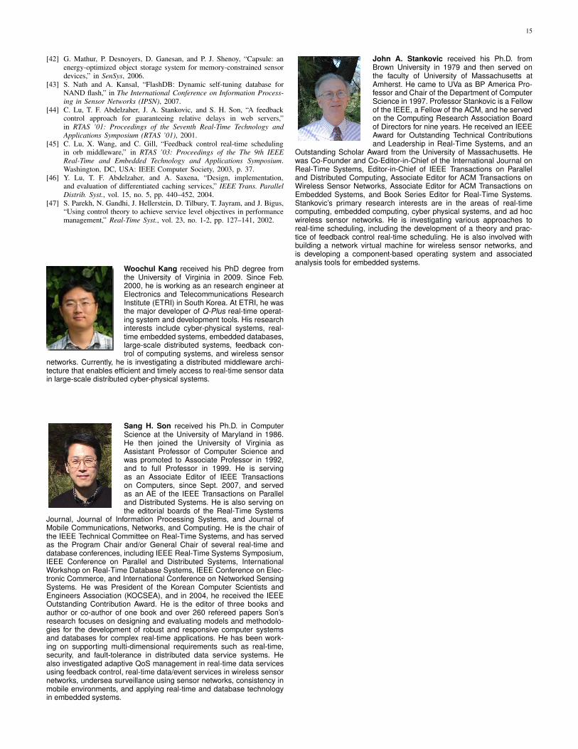
15
[42] G. Mathur, P. Desnoyers, D. Ganesan, and P. J. Shenoy, “Capsule: anenergy-optimized object storage system for memory-constrained sensordevices,” in SenSys, 2006.
[43] S. Nath and A. Kansal, “FlashDB: Dynamic self-tuning database forNAND flash,” in The International Conference on Information Process-
ing in Sensor Networks (IPSN), 2007.[44] C. Lu, T. F. Abdelzaher, J. A. Stankovic, and S. H. Son, “A feedback
control approach for guaranteeing relative delays in web servers,”in RTAS ’01: Proceedings of the Seventh Real-Time Technology and
Applications Symposium (RTAS ’01), 2001.[45] C. Lu, X. Wang, and C. Gill, “Feedback control real-time scheduling
in orb middleware,” in RTAS ’03: Proceedings of the The 9th IEEE
Real-Time and Embedded Technology and Applications Symposium.Washington, DC, USA: IEEE Computer Society, 2003, p. 37.
[46] Y. Lu, T. F. Abdelzaher, and A. Saxena, “Design, implementation,and evaluation of differentiated caching services,” IEEE Trans. Parallel
Distrib. Syst., vol. 15, no. 5, pp. 440–452, 2004.[47] S. Parekh, N. Gandhi, J. Hellerstein, D. Tilbury, T. Jayram, and J. Bigus,
“Using control theory to achieve service level objectives in performancemanagement,” Real-Time Syst., vol. 23, no. 1-2, pp. 127–141, 2002.
Woochul Kang received his PhD degree fromthe University of Virginia in 2009. Since Feb.2000, he is working as an research engineer atElectronics and Telecommunications ResearchInstitute (ETRI) in South Korea. At ETRI, he wasthe major developer of Q-Plus real-time operat-ing system and development tools. His researchinterests include cyber-physical systems, real-time embedded systems, embedded databases,large-scale distributed systems, feedback con-trol of computing systems, and wireless sensor
networks. Currently, he is investigating a distributed middleware archi-tecture that enables efficient and timely access to real-time sensor datain large-scale distributed cyber-physical systems.
Sang H. Son received his Ph.D. in ComputerScience at the University of Maryland in 1986.He then joined the University of Virginia asAssistant Professor of Computer Science andwas promoted to Associate Professor in 1992,and to full Professor in 1999. He is servingas an Associate Editor of IEEE Transactionson Computers, since Sept. 2007, and servedas an AE of the IEEE Transactions on Paralleland Distributed Systems. He is also serving onthe editorial boards of the Real-Time Systems
Journal, Journal of Information Processing Systems, and Journal ofMobile Communications, Networks, and Computing. He is the chair ofthe IEEE Technical Committee on Real-Time Systems, and has servedas the Program Chair and/or General Chair of several real-time anddatabase conferences, including IEEE Real-Time Systems Symposium,IEEE Conference on Parallel and Distributed Systems, InternationalWorkshop on Real-Time Database Systems, IEEE Conference on Elec-tronic Commerce, and International Conference on Networked SensingSystems. He was President of the Korean Computer Scientists andEngineers Association (KOCSEA), and in 2004, he received the IEEEOutstanding Contribution Award. He is the editor of three books andauthor or co-author of one book and over 260 refereed papers Son’sresearch focuses on designing and evaluating models and methodolo-gies for the development of robust and responsive computer systemsand databases for complex real-time applications. He has been work-ing on supporting multi-dimensional requirements such as real-time,security, and fault-tolerance in distributed data service systems. Healso investigated adaptive QoS management in real-time data servicesusing feedback control, real-time data/event services in wireless sensornetworks, undersea surveillance using sensor networks, consistency inmobile environments, and applying real-time and database technologyin embedded systems.
John A. Stankovic received his Ph.D. fromBrown University in 1979 and then served onthe faculty of University of Massachusetts atAmherst. He came to UVa as BP America Pro-fessor and Chair of the Department of ComputerScience in 1997. Professor Stankovic is a Fellowof the IEEE, a Fellow of the ACM, and he servedon the Computing Research Association Boardof Directors for nine years. He received an IEEEAward for Outstanding Technical Contributionsand Leadership in Real-Time Systems, and an
Outstanding Scholar Award from the University of Massachusetts. Hewas Co-Founder and Co-Editor-in-Chief of the International Journal onReal-Time Systems, Editor-in-Chief of IEEE Transactions on Paralleland Distributed Computing, Associate Editor for ACM Transactions onWireless Sensor Networks, Associate Editor for ACM Transactions onEmbedded Systems, and Book Series Editor for Real-Time Systems.Stankovic’s primary research interests are in the areas of real-timecomputing, embedded computing, cyber physical systems, and ad hocwireless sensor networks. He is investigating various approaches toreal-time scheduling, including the development of a theory and prac-tice of feedback control real-time scheduling. He is also involved withbuilding a network virtual machine for wireless sensor networks, andis developing a component-based operating system and associatedanalysis tools for embedded systems.