Embed Size (px)
Citation preview

Design-in guidePhilips Fortimo LED Line Systems Gen 2 -LV
2 Philips Fortimo LED Line Systems Generation 2 – LV
ContentsIntroduction to this guide 3
Warnings and instructions for LV products 3
When using an isolated driver, intended for LV products 3
Design In Phase 3
Introducing the Fortimo LED Line Gen 2 System 5
Applications and luminaire classification 5
Commercial naming of the Fortimo LED Line modules 5
In this design-in guide 5
Zhaga 6
General remark on wiring 6
Electrical design-in 6
Xitanium Indoor Linear LED drivers 6
Choose the LED current 8
System configurations with LED Line gen2 8
Cables 10
Automatic wiring with robot 10
Mechanical design-in 11
Mechanical fixation for LED Line 11
Alternative fixation methodes 12
Optical design-in 13
Optics ontop or near the LED Line module 13
Thermal design-in 14
Introduction 14
Xitanium drivers 14
Tc point 14
Choose the maximum Tc 15
Influence of thermal resitance of the luminaire 16
Cooling via the luminaire housing or cooling plate 16
Tips for small volume and double chamber conditions 18
General thermal recommendations 18
Reliability 19
Lumen maintenance of the Fortimo LED Line 19
Tips and instructions for assembly and installation 21
Inserting and removing the cable connectors 21
Binning 23
EMC 23
Electrostatic discharge (ESD) 24
Controllability 25
Dimming 25
Stand-alone Philips systems 25
Compliance and approval 26
Chemical compatibility 26
Compliance and approval marks 26
IP rating, humidity and condensation 26
Photobiological safety 26
Electromagnetic compatibility 27
System disposal 27
Safety 27
Electromagnetic compatibility 27
Cautions during storage and transportation 28
Philips Fortimo LED Line Systems Generation 2 – LV 3
Introduction to this guide
Warnings and instructions for LV products
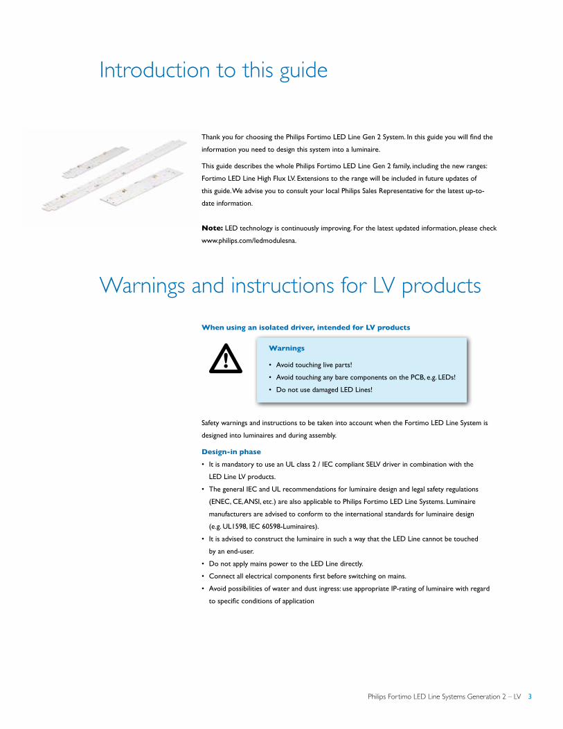
Thank you for choosing the Philips Fortimo LED Line Gen 2 System. In this guide you will find the
information you need to design this system into a luminaire.
This guide describes the whole Philips Fortimo LED Line Gen 2 family, including the new ranges:
Fortimo LED Line High Flux LV. Extensions to the range will be included in future updates of
this guide. We advise you to consult your local Philips Sales Representative for the latest up-to-
date information.
Note: LED technology is continuously improving. For the latest updated information, please check
www.philips.com/ledmodulesna.
When using an isolated driver, intended for LV products
Warnings
• Avoid touching live parts!
• Avoid touching any bare components on the PCB, e.g. LEDs!
• Do not use damaged LED Lines!
Safety warnings and instructions to be taken into account when the Fortimo LED Line System is
designed into luminaires and during assembly.
Design-in phase
• It is mandatory to use an UL class 2 / IEC compliant SELV driver in combination with the
LED Line LV products.
• The general IEC and UL recommendations for luminaire design and legal safety regulations
(ENEC, CE, ANSI, etc.) are also applicable to Philips Fortimo LED Line Systems. Luminaire
manufacturers are advised to conform to the international standards for luminaire design
(e.g. UL1598, IEC 60598-Luminaires).
• It is advised to construct the luminaire in such a way that the LED Line cannot be touched
by an end-user.
• Do not apply mains power to the LED Line directly.
• Connect all electrical components first before switching on mains.
• Avoid possibilities of water and dust ingress: use appropriate IP-rating of luminaire with regard
to specific conditions of application
Controllability 25
Dimming 25
Stand-alone Philips systems 25
Compliance and approval 26
Chemical compatibility 26
Compliance and approval marks 26
IP rating, humidity and condensation 26
Photobiological safety 26
Electromagnetic compatibility 27
System disposal 27
Safety 27
Electromagnetic compatibility 27
Cautions during storage and transportation 28
!

4 Philips Fortimo LED Line Systems Generation 2 – LV
Warnings and instructions for LV products
Manufacturing phase
• Do not use damaged or defective LED Lines, including damaged connectors or PCB.
• Do not drop the LED Line or let any object fall onto the LED Line because this may damage
the PCB or LEDs and affect proper functioning of the product.
• Connect all electrical components first before switching on mains
Installation and service for luminaires incorporating the Fortimo LED
Line System
• Do not service the luminaire when the mains voltage is connected; this includes connecting
or disconnecting the LED Line cable.
• Do not use damaged products.
For optimal reliability of the LED Line we advise against applying an AC electric strength test to the
luminaire as this might damage the LEDs. Recommend instead is applying an insulation resistance
measurement at 500 V DC (noted as alternative test in IEC/EN 60598-1 annex Q).
Philips Fortimo LED Line Systems Generation 2 – LV 5
Introducing the Fortimo LED Line Gen 2 System
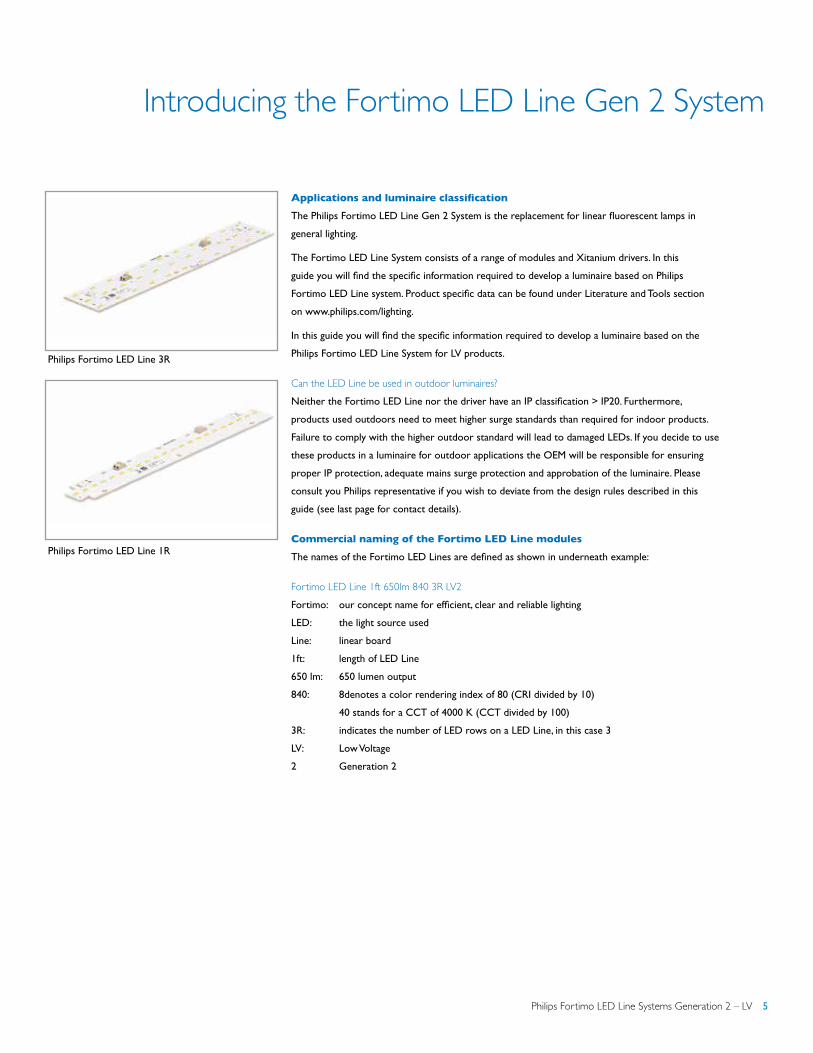
Applications and luminaire classification
The Philips Fortimo LED Line Gen 2 System is the replacement for linear fluorescent lamps in
general lighting.
The Fortimo LED Line System consists of a range of modules and Xitanium drivers. In this
guide you will find the specific information required to develop a luminaire based on Philips
Fortimo LED Line system. Product specific data can be found under Literature and Tools section
on www.philips.com/lighting.
In this guide you will find the specific information required to develop a luminaire based on the
Philips Fortimo LED Line System for LV products.
Can the LED Line be used in outdoor luminaires? Neither the Fortimo LED Line nor the driver have an IP classification > IP20. Furthermore,
products used outdoors need to meet higher surge standards than required for indoor products.
Failure to comply with the higher outdoor standard will lead to damaged LEDs. If you decide to use
these products in a luminaire for outdoor applications the OEM will be responsible for ensuring
proper IP protection, adequate mains surge protection and approbation of the luminaire. Please
consult you Philips representative if you wish to deviate from the design rules described in this
guide (see last page for contact details).
Commercial naming of the Fortimo LED Line modules
The names of the Fortimo LED Lines are defined as shown in underneath example:
Fortimo LED Line 1ft 650lm 840 3R LV2
Fortimo: our concept name for efficient, clear and reliable lighting
LED: the light source used
Line: linear board
1ft: length of LED Line
650 lm: 650 lumen output
840: 8denotes a color rendering index of 80 (CRI divided by 10)
40 stands for a CCT of 4000 K (CCT divided by 100)
3R: indicates the number of LED rows on a LED Line, in this case 3
LV: Low Voltage
2 Generation 2
Philips Fortimo LED Line 3R
Philips Fortimo LED Line 1R

6 Philips Fortimo LED Line Systems Generation 2 – LV
Introducing the Fortimo LED Line Gen 2 System
Electrical design-in
In this design-in guide
In this design-in guide you will find all necessary guidelines to configure the Fortimo LED Line
system to exactly your needs. The Fortimo LED Line range is designed to enable all types of
luminaires in general lighting that traditionally were equipped with fluorescent tubes.
The range exits of
• Fortimo LED Line Gen 2 → focus on mainstream fluorescent replacement
• Fortimo LED Line High Flux → focus on higher lumen packages
On top of this broad range in standard settings and building blocks, the Fortimo LED Line portfolio
provides the luminaire manufacturer with a high level of flexibility to differentiate its luminaire, to
design a specific luminaire performance and change settings of luminaire in the factory while using
the same components.
Zhaga
Almost every LED Line module is Zhaga certified. Please check the associated datasheet of the LED
Line you are using for details.
General remark on wiring
With respect to LED Lines Gen 1, LED Lines Gen 2 have the same wiring approach except that
there are no longer pre-defined cables with polarity-defined connectors.
In this section you will find all of the product information needed to design a configuration based
on the Fortimo LED Line Gen 2 System. These systems typically consist of the following products:
• Fortimo LED Line modules
• Philips Advance Xitanium Indoor Linear LED Drivers
• Standard installation wire (solid core, not provided by Philips)
• Optionally a resistor to set the output current (not provided by Philips)
Xitanium Indoor Linear LED Drivers
For detailed info, please refer to the associated drivers datasheets.
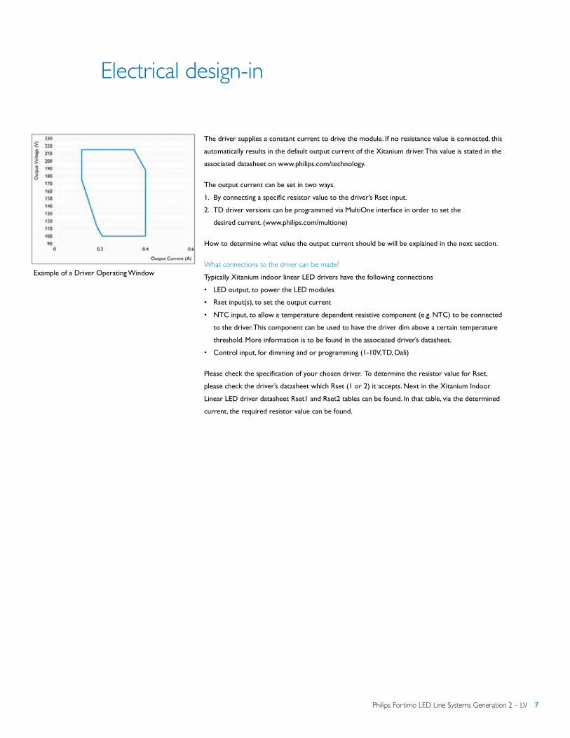
Xitanium driver operating window The Xitanium LED drivers have a voltage and a current range, known as the ‘operating window’.
This means that multiple combinations of modules and drivers are possible. The graph shows an
example operating window of a Xitanium driver.
¥
¥ Philips Fortimo LED Line Module is a Zhaga certified light engine. For more information visit www.zhagastandard.org
Philips Fortimo LED Line Systems Generation 2 – LV 7
Electrical design-in
The driver supplies a constant current to drive the module. If no resistance value is connected, this
automatically results in the default output current of the Xitanium driver. This value is stated in the
associated datasheet on www.philips.com/technology.
The output current can be set in two ways.
1. By connecting a specific resistor value to the driver’s Rset input.
2. TD driver versions can be programmed via MultiOne interface in order to set the
desired current. (www.philips.com/multione)
How to determine what value the output current should be will be explained in the next section.
What connections to the driver can be made? Typically Xitanium indoor linear LED drivers have the following connections
• LED output, to power the LED modules
• Rset input(s), to set the output current
• NTC input, to allow a temperature dependent resistive component (e.g. NTC) to be connected
to the driver. This component can be used to have the driver dim above a certain temperature
threshold. More information is to be found in the associated driver’s datasheet.
• Control input, for dimming and or programming (1-10V, TD, Dali)
Please check the specification of your chosen driver. To determine the resistor value for Rset,
please check the driver’s datasheet which Rset (1 or 2) it accepts. Next in the Xitanium Indoor
Linear LED driver datasheet Rset1 and Rset2 tables can be found. In that table, via the determined
current, the required resistor value can be found.
Example of a Driver Operating Window
8 Philips Fortimo LED Line Systems Generation 2 – LV
Electrical design-in
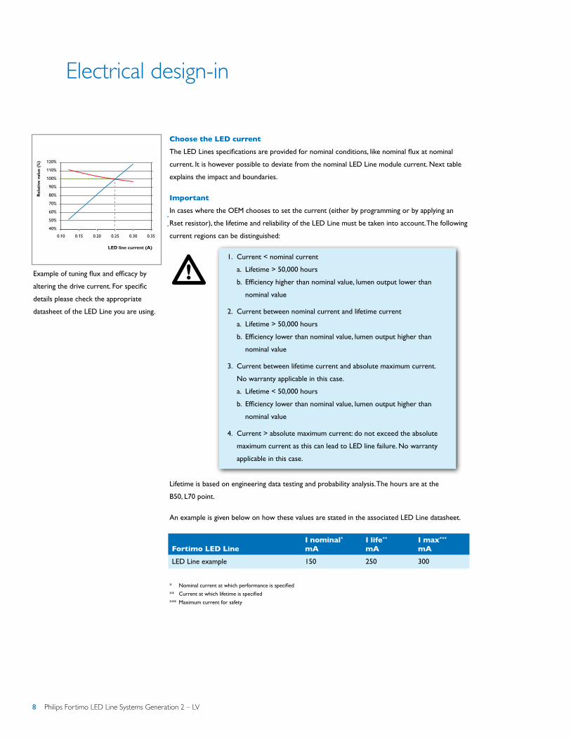
Choose the LED current
The LED Lines specifications are provided for nominal conditions, like nominal flux at nominal
current. It is however possible to deviate from the nominal LED Line module current. Next table
explains the impact and boundaries.
Important
In cases where the OEM chooses to set the current (either by programming or by applying an
Rset resistor), the lifetime and reliability of the LED Line must be taken into account. The following
current regions can be distinguished:
1. Current < nominal current
a. Lifetime > 50,000 hours
b. Efficiency higher than nominal value, lumen output lower than
nominal value
2. Current between nominal current and lifetime current
a. Lifetime > 50,000 hours
b. Efficiency lower than nominal value, lumen output higher than
nominal value
3. Current between lifetime current and absolute maximum current.
No warranty applicable in this case.
a. Lifetime < 50,000 hours
b. Efficiency lower than nominal value, lumen output higher than
nominal value
4. Current > absolute maximum current: do not exceed the absolute
maximum current as this can lead to LED line failure. No warranty
applicable in this case.
Lifetime is based on engineering data testing and probability analysis. The hours are at the
B50, L70 point.
An example is given below on how these values are stated in the associated LED Line datasheet.
System configurations with LED Line Gen 2
* Nominal current at which performance is specified
** Current at which lifetime is specified
*** Maximum current for safety
Example of tuning flux and efficacy by
altering the drive current. For specific
details please check the appropriate
datasheet of the LED Line you are using.
!
Fortimo LED LineI nominal* mA
I life** mA
I max*** mA
LED Line example 150 250 300
0.10 0.15 0.20 0.25 0.30 0.35
LED line current (A)
50%
40%
60%
70%
80%
90%
100%
110%
120%
Efficacy
Luminous flux
Rel
ativ
e va
lue
(%)
Philips Fortimo LED Line Systems Generation 2 – LV 9
Electrical design-in
When configuring the system with the Philips Advance driver and Fortimo LED Line Module,
the final driver operating point needs to be within the driver operating window. The following
guidelines may help in determining the optimum driver operating point. In case of questions,
contact your local Philips Sales Representative or the Philips Design-In Team.
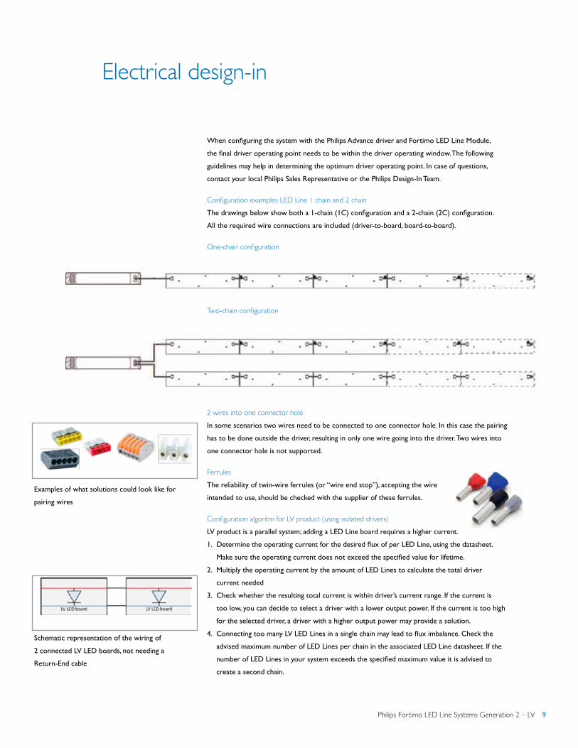
Configuration examples LED Line 1 chain and 2 chain The drawings below show both a 1-chain (1C) configuration and a 2-chain (2C) configuration.
All the required wire connections are included (driver-to-board, board-to-board).
One-chain configuration
Two-chain configuration
2 wires into one connector hole In some scenarios two wires need to be connected to one connector hole. In this case the pairing
has to be done outside the driver, resulting in only one wire going into the driver. Two wires into
one connector hole is not supported.
Ferrules The reliability of twin-wire ferrules (or “wire end stop”), accepting the wire
intended to use, should be checked with the supplier of these ferrules.
Configuration algoritm for LV product (using isolated drivers) LV product is a parallel system; adding a LED Line board requires a higher current.
1. Determine the operating current for the desired flux of per LED Line, using the datasheet.
Make sure the operating current does not exceed the specified value for lifetime.
2. Multiply the operating current by the amount of LED Lines to calculate the total driver
current needed
3. Check whether the resulting total current is within driver’s current range. If the current is
too low, you can decide to select a driver with a lower output power. If the current is too high
for the selected driver, a driver with a higher output power may provide a solution.
4. Connecting too many LV LED Lines in a single chain may lead to flux imbalance. Check the
advised maximum number of LED Lines per chain in the associated LED Line datasheet. If the
number of LED Lines in your system exceeds the specified maximum value it is advised to
create a second chain.
Examples of what solutions could look like for
pairing wires
Schematic representation of the wiring of
2 connected LV LED boards, not needing a
Return-End cable
10 Philips Fortimo LED Line Systems Generation 2 – LV
Electrical design-in
Most isolated drivers enable the connection of two chains of LED Lines. Note that the number of
LED Lines per chain does not have to be the same for all chains, since all LED Lines are electrically
connected in parallel.
Note: LV product does not make use of a Return-End connection
Mixing different Fortimo LED Line Modules Please note that although different types of Fortimo LED Line Modules can be connected
to one another, only combinations indicated in the datasheets are allowed. Another reason being
that the voltage and current requirements differ per type and by mixing this can lead to undesired
performance differences. If you wish to deviate by mixing other types, please consult your local
Philips Representative.
Cables With the Fortimo LED Lines Gen 2 standard solid core installation wire can be used. This approach
allows the OEM to choose the preferred cable properties like color, thickness and lengths, although
mains-rated wiring is advised. Please check the LED module and driver datasheet for details like
thickness and strip length.
Automatic wiring with robot Equipped with a new connector, Fortimo LED Line Gen 2 Module is now allows for automatic
robot wiring. As do the latest Philips Advance Xitanium Indoor Linear LED drivers. For
implementation details please check with your robot manufacturer.
General remark on wiring With respect to LED Lines Gen 1 modules, LED Lines Gen 2 modules have the same
wiring approach, being different only in that there are no longer pre-defined cables or
polarity-defined connectors.
Connecting the modules to the driver On the module each connector is marked ‘IN’ or ‘OUT’ and has both a ‘+’ and ‘-’. They are
polarity sensitive. Please assure a correct wiring before switching on the LED driver. In a ‘2-chain’
configuration, 2 plusses and 2 minuses have to be connected to the driver.
Interconnecting LED Lines Default the cables are connected from the ‘OUT’ connector of a module to the ‘IN’ connector of
the neighboring module, keeping the polarity (‘+’ and ‘-‘) consistent. LED Lines are polarity sensitive.
Please assure a correct wiring before switching on the LED driver.
Philips Fortimo LED Line Systems Generation 2 – LV 11
Electrical design-in
Mechanical design-in
Connecting the driver to the mains supply The mains supply has to be connected to the LED driver, not the LED board.
Warning
Connecting the luminaire to protective earth If the driver requires being connected to protective earth, like non-isolated
Philips Advance Xitanium LED drivers, the luminaire needs to be connected
to protective earth in order to comply with safety regulations and EMI.
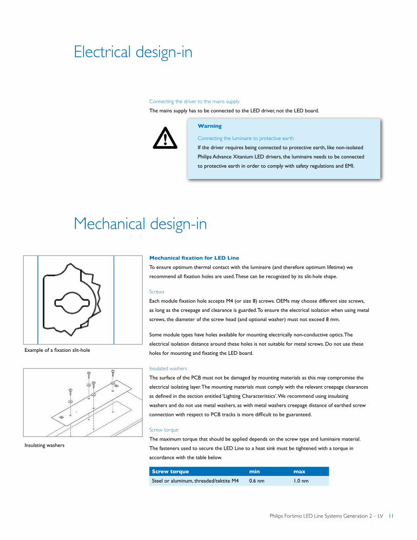
Mechanical fixation for LED Line To ensure optimum thermal contact with the luminaire (and therefore optimum lifetime) we
recommend all fixation holes are used. These can be recognized by its slit-hole shape.
Screws Each module fixation hole accepts M4 (or size 8) screws. OEMs may choose different size screws,
as long as the creepage and clearance is guarded. To ensure the electrical isolation when using metal
screws, the diameter of the screw head (and optional washer) must not exceed 8 mm.
Some module types have holes available for mounting electrically non-conductive optics. The
electrical isolation distance around these holes is not suitable for metal screws. Do not use these
holes for mounting and fixating the LED board.
Insulated washersThe surface of the PCB must not be damaged by mounting materials as this may compromise the
electrical isolating layer. The mounting materials must comply with the relevant creepage clearances
as defined in the section entitled ‘Lighting Characteristics’. We recommend using insulating
washers and do not use metal washers, as with metal washers creepage distance of earthed screw
connection with respect to PCB tracks is more difficult to be guaranteed.
Screw torqueThe maximum torque that should be applied depends on the screw type and luminaire material.
The fasteners used to secure the LED Line to a heat sink must be tightened with a torque in
accordance with the table below.
!
Screw torque min max
Steel or aluminum, threaded/tektite M4 0.6 nm 1.0 nm
Example of a fixation slit-hole
Insulating washers

12 Philips Fortimo LED Line Systems Generation 2 – LV
Mechanical design-in
Alternative fixation methodes With Fortimo LED Line Gen 2 module fixation methods can be explored, leading to fewer screws
and faster mounting times. In order to achieve this, larger copper-free isles around the mounting
holes are designed. This freedom applies to the whole Fortimo LED Line Gen 2 portfolio.
Examples of a one-screw fixation with clamps for LED Lines Screw or alike Clamp or alike
Philips Fortimo LED Line Systems Generation 2 – LV 13
Optical design-in
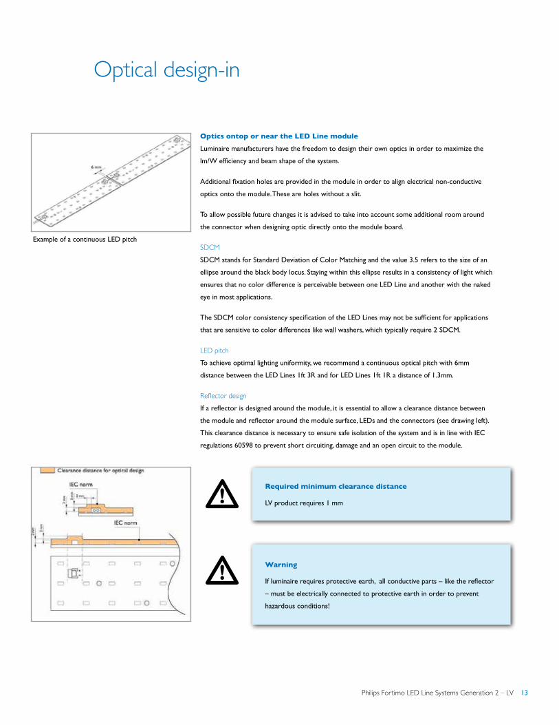
Optics ontop or near the LED Line module Luminaire manufacturers have the freedom to design their own optics in order to maximize the
lm/W efficiency and beam shape of the system.
Additional fixation holes are provided in the module in order to align electrical non-conductive
optics onto the module. These are holes without a slit.
To allow possible future changes it is advised to take into account some additional room around
the connector when designing optic directly onto the module board.
SDCMSDCM stands for Standard Deviation of Color Matching and the value 3.5 refers to the size of an
ellipse around the black body locus. Staying within this ellipse results in a consistency of light which
ensures that no color difference is perceivable between one LED Line and another with the naked
eye in most applications.
The SDCM color consistency specification of the LED Lines may not be sufficient for applications
that are sensitive to color differences like wall washers, which typically require 2 SDCM.
LED pitchTo achieve optimal lighting uniformity, we recommend a continuous optical pitch with 6mm
distance between the LED Lines 1ft 3R and for LED Lines 1ft 1R a distance of 1.3mm.
Reflector design If a reflector is designed around the module, it is essential to allow a clearance distance between
the module and reflector around the module surface, LEDs and the connectors (see drawing left).
This clearance distance is necessary to ensure safe isolation of the system and is in line with IEC
regulations 60598 to prevent short circuiting, damage and an open circuit to the module.
Required minimum clearance distance
LV product requires 1 mm
Warning
If luminaire requires protective earth, all conductive parts – like the reflector
– must be electrically connected to protective earth in order to prevent
hazardous conditions!
Example of a continuous LED pitch
!
!
14 Philips Fortimo LED Line Systems Generation 2 – LV
Thermal design-in
Introduction To facilitate design-in of Fortimo LED Line Systems, the critical thermal management points of the
module and driver are set out in this section. The design of the product is intended to keep the
component temperature as low as possible, but the design of the luminaire and the ability to guide
the heat out of the luminaire are of utmost importance. If these thermal points are taken into
account this will help ensure the optimum performance and lifetime of the system.
Definitions• Module temperature: temperature measured at the Tc point of the LED Line module
• Ambient temperature: temperature outside the luminaire
When switched off >2 hours, temperature at Tc point should equal to the ambient temperature.
Xitanium drivers
Besides the LED Lines another important component is the driver. For specific design-in guidelines
please consult the associated design-in guide for the Xitanium indoor linear LED drivers and the
associated driver datasheet.
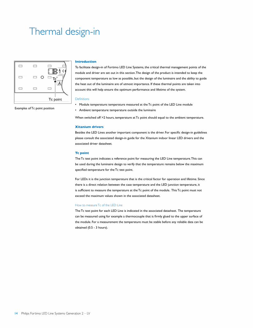
Tc point
The Tc test point indicates a reference point for measuring the LED Line temperature. This can
be used during the luminaire design to verify that the temperature remains below the maximum
specified temperature for the Tc test point.
For LEDs it is the junction temperature that is the critical factor for operation and lifetime. Since
there is a direct relation between the case temperature and the LED junction temperature, it
is sufficient to measure the temperature at the Tc point of the module. This Tc point must not
exceed the maximum values shown in the associated datasheet.
How to measure Tc of the LED Line The Tc test point for each LED Line is indicated in the associated datasheet. The temperature
can be measured using for example a thermocouple that is firmly glued to the upper surface of
the module. For a measurement the temperature must be stable before any reliable data can be
obtained (0.5 - 3 hours).
Examples of Tc point position

Philips Fortimo LED Line Systems Generation 2 – LV 15
!
Thermal design-in
Relation between flux and TcThe flux of the module is specified at a nominal Tc, which is a lower value than the maximum Tc
corresponding to the lifetime specification. Increasing the Tc temperature has an adverse effect on
the flux and lifetime of the module.
Relation between T (ambient) and fluxTc approximately increases in a linear fashion with the ambient temperature. The temperature
offset between T (ambient) and Tc depends on the thermal design of the luminaire. The Fortimo
LED Line System has been designed for indoor use. For approved ambient temperature range
please check the associated LED Line datasheet.
Choose the maximum Tc In previous sections it has been explained how to determine the Tc. It is however possible to
deviate from the nominal LED Line module Tc. Next section explains the impact and boundaries.
Important
In cases where the OEM chooses to allow the temperature at the Tc point to
exceed the temperature to assure lifetime (Tc-life) the lifetime and reliability
of the LED Line must be taken into account. Given a constant current,
following temperature regions can be distinguished:
1. Temperature at Tc < nominal value
a. Lifetime > 50,000 hours
b. Efficiency higher than nominal value, lumen output slightly
higher than nominal value
2. Temperature at Tc between nominal value and lifetime value
a. Lifetime > 50,000 hours
b. Efficiency lower than nominal value, lumen output slightly
lower than nominal value
3. Temperature at Tc between lifetime value and absolute maximum value.
No warranty applicable in this case.
a. Lifetime < 50,000 hours
b. Efficiency lower than nominal value, lumen output lower
than nominal value
4. Temperature at Tc > absolute maximum value: do not exceed the
absolute maximum value as this can lead to LED line failure. No warranty
applicable in this case.
Example of altering flux and efficiency by
allowing a different Tc. For specific details please
check the associated datasheet of the LED Line
you are using.

16 Philips Fortimo LED Line Systems Generation 2 – LV
Thermal design-in
Lifetime is based on engineering data testing and probability analysis. The hours are at the
B50, L70 point.
An example is given below on how these values are stated in the associated LED Line datasheet.
Please make sure to look up the corresponding Tc values for the Fortimo LED Line product you
are using.
Influence of thermal resitance of the luminaire
Retrofitting Fortimo LED Line Gen 2 Systems into existing fluorescent fixtures is possible in
many cases. However, in case of a high flux LED Line - with a high power density – the luminaire
design has to enable sufficient heat transfer from the LED Line to ambient. In other words, the
higher the flux density (lm/ft) the lower the total thermal resistance (Rth) from the module to the
ambient has to be in order to keep the module temperature at the specified level. The total Rth is
determined by both the module and the luminaire design. The lower the Rth, the better the thermal
performance of the system.
In case the measured Tc value of the module inside the luminaire is higher than specified and the
luminaire design cannot be modified, reducing the module current can provide a solution.
The total Rth can be calculated from the measured difference between Tc and Tambient and the
module current and voltage by the following formula:
Cooling via the luminaire housing or cooling plate
Thermal contactThe unflatness (air gap) of the area where the LED Line is mounted should not exceed 1 mm along
the LED Line length to ensure good thermal contact and to avoid local stress and strain on the
LED Line. By ensuring good thermal contact between the bottom surface and the luminaire surface
thermal paste almost certain is needless. Preventing an air gap is ensuring the best thermal contact.
2 Minimum Tc at which performance is specified
3 Maximum Tc at which lifetime is specified
4 Maximum Tc for safety
Rth=(Tc – Tambient)
V • I
Fortimo LED LineTc min2 °C
Tc life3 °C
Tc max4 °C
LED Line example 45 55 65

Philips Fortimo LED Line Systems Generation 2 – LV 17
Thermal design-in
Cooling via the luminaire housingThe Fortimo LED Line itself has been optimized to spread the generated heat. However, extra
cooling can be achieved via the luminaire housing or, if this is not sufficient, via an extra cooling
plate. For this to work well, good thermal contact must be achieved. Obviously the plate must
release its heat via the luminaire to the surroundings as well.
Cooling surface area and materialThe amount of heat that needs to be transferred away from the LED Line to the ambient air
is about two thirds of the electrical power. This heat needs to be dissipated and transferred to
ambient air via the luminaire housing.
If the luminaire housing has a good thermal conductivity the effective cooling area is increased.
It is therefore recommended to use a material that has high thermal conductivity and is of
sufficient thickness. This will lower the Tc temperature and enable the system to perform better
(lifetime and flux).
The required size of the luminaire housing area per LED Line depends on the design and volume of
the luminaire, the thermal properties of the material used and the expected ambient temperature.
Aluminum is preferred over steel because of its higher thermal conductivity, although for most
applications steel is likely to be adequate for ambient temperatures of up to about 40 °C. If Tc is
exceeding the target value, consider the use of aluminum.
Material k (W/mK)
Copper 400
Aluminum 200
Brass 100
Steel 50
Corrosion-resistant steel 15
The unflatness of the area where the
module is mounted should not exceed
1 mm along the module.
Thermal conductivity of different materials
Effect on Tc of the mounting plate material, thickness and width

18 Philips Fortimo LED Line Systems Generation 2 – LV
Thermal design-in
The following examples show that the heat is transferred in a correct way
Tips for small volume and double chamber conditions
The heat produced by the module and driver in the luminaire (or similar housing) must be
dissipated to the surroundings. If a luminaire is thermally insulated by a ceiling, wall or insulation
blanket, the heat produced cannot be easily dissipated. This will result in a higher temperature
of the driver and module, which will have an adverse effect on system performance and lifetime.
For optimum performance and lifetime it is advised that air be allowed to flow freely around the
luminaire and that the mounting plate is in direct thermal contact with free air. Designing the
luminaire in such a way that air can also flow through it will provide extra cooling, which may be
beneficial in certain cases.
General thermal recommendations
General thermal design guidelines to improve the thermal management and performance
of a luminaire:
• Simplify the heat path from Tc to cold ambient air; less interfaces is better
• Use good thermally conductive materials in the primary heat path
• Ensure proper heat spreading by using materials with good conductivity and/or sufficient
1 mm steel 1 mm aluminium
Temperature distribution using different mounting plate materials
Operation under built-in conditions, applicable for both LED module and driver
Philips Fortimo LED Line Systems Generation 2 – LV 19
Thermal design-in
Reliability
thickness to increase the effective cooling surfaces
• Anodized, painted surfaces are preferable to blank surfaces in order to increase heat transfer
via thermal radiation
• Use of thermal interface materials (TIM) can be considered to improve thermal contact,
i.e. between the module and luminaire housing
Contact Philips Sales Representative at any time if you need advice on your luminaire design.
Lumen maintenance of the Fortimo LED Line
B50L70 @ 50000 hours
The quality of the Led Line portfolio is underpinned with Philips’ claim of B50L70 @ 50000 hours.
This means that at 50000 hours of operation at least 50% of the LEDs’ population will emit at least
70% of its original amount of lumens.
In this section the example graphs show the estimated lumen depreciation curves for different
percentage of the population and for different Tc temperatures. The actual data for the LED Line
modules can be found in the associated datasheet.
These estimations are based on 9000 hours of LM80 testing and calculated according to the TM-21
guideline. After 50,000 hours the lines are dotted, because lumen maintenance beyond 50,000
hours cannot be predicted according to the TM-21 guideline. Lowering the drive current and or
temperature can increase the lumen maintenance time.
Please refer to the associated LED Line datasheet for the specific graphs.

20 Philips Fortimo LED Line Systems Generation 2 – LV
Reliability
Lumen maintenance for B10 and B50Below example graph is showing the lumen maintenance (% of initial lumen over time) for B50
(50% of the population) and B10 (90% of the population).
Example lumen maintenance as a function of operating hours for B10 and B50
Please look up the actual lumen maintenance graph in the associated datasheet of the Fortimo LED
Line you are using.
Lumen maintenance for for different Tc temperaturesLumen maintenance is also affected by temperature. Lowering the Tc will increase the lumen
maintenance time. Below example graph is showing the lumen maintenance (% of initial lumen over
time) for B50 (50% of the population) at I life and three different Tc temperatures (Tc nominal, life
and maximum).
Example lumen maintenance as a function of operating hours at different Tc values
Philips Fortimo LED Line Systems Generation 2 – LV 21
!
Reliability
Tips and instructions for assembly and installation
Note: above graphs are lifetime predictions based on LM80 data; no guarantee outside specified
lifetime specifications.
Warning
Do not service the system when the mains voltage is connected.
This includes connecting or disconnecting the cable.
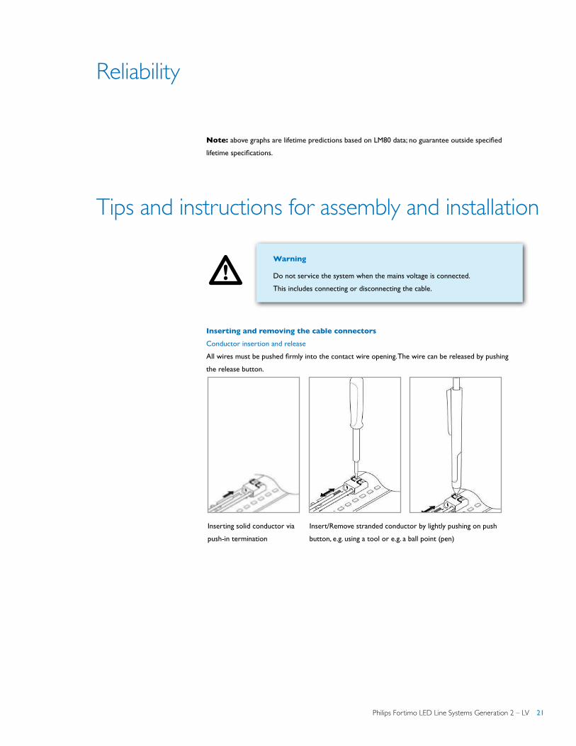
Inserting and removing the cable connectors
Conductor insertion and release
All wires must be pushed firmly into the contact wire opening. The wire can be released by pushing
the release button.
Inserting solid conductor via
push-in termination
Insert/Remove stranded conductor by lightly pushing on push
button, e.g. using a tool or e.g. a ball point (pen)
22 Philips Fortimo LED Line Systems Generation 2 – LV
!
Tips and instructions for assembly and installation
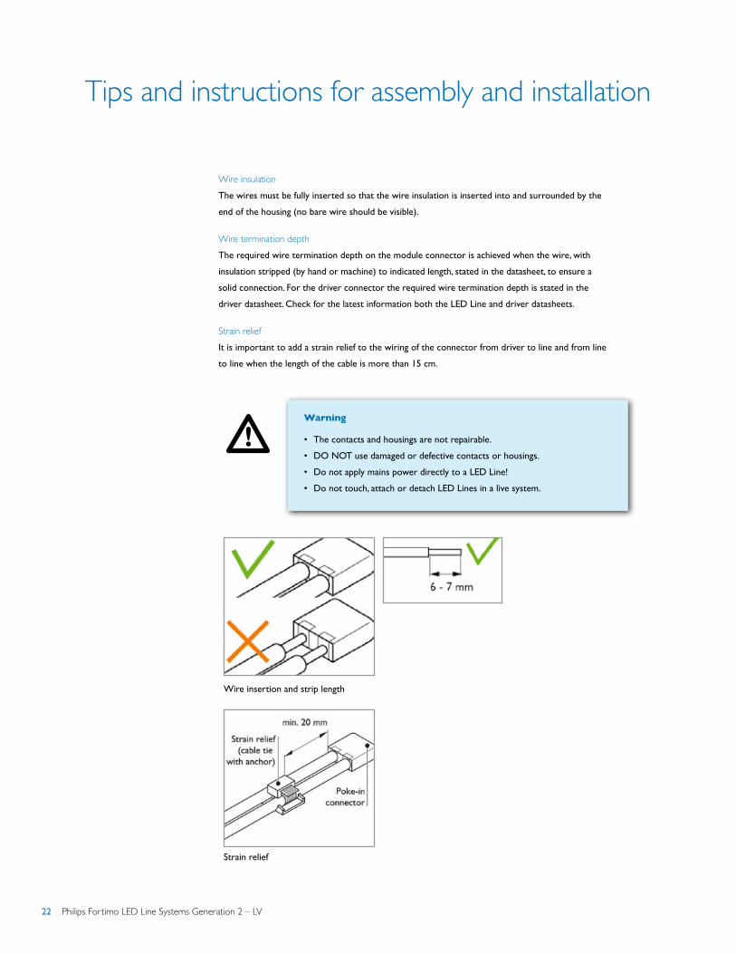
Wire insulationThe wires must be fully inserted so that the wire insulation is inserted into and surrounded by the
end of the housing (no bare wire should be visible).
Wire termination depthThe required wire termination depth on the module connector is achieved when the wire, with
insulation stripped (by hand or machine) to indicated length, stated in the datasheet, to ensure a
solid connection. For the driver connector the required wire termination depth is stated in the
driver datasheet. Check for the latest information both the LED Line and driver datasheets.
Strain reliefIt is important to add a strain relief to the wiring of the connector from driver to line and from line
to line when the length of the cable is more than 15 cm.
Warning
• The contacts and housings are not repairable.
• DO NOT use damaged or defective contacts or housings.
• Do not apply mains power directly to a LED Line!
• Do not touch, attach or detach LED Lines in a live system.
Wire insertion and strip length
Strain relief
Philips Fortimo LED Line Systems Generation 2 – LV 23
Tips and instructions for assembly and installation
Binning
Philips has created high-quality LED light by ensuring correct mixing of the LED bins within each
module. There is a limited need for binning of LED Lines in two bins only for the Linear boards.
Fortimo LED Line modules are labeled and packaged in maximum two voltage bins. LED Line linear
is divided into bins, indicated with two letters, for example ‘A’ and ‘C’. In order to ensure optimum
flux and color uniformity, we advise against mixing two different bins in the same luminaire.
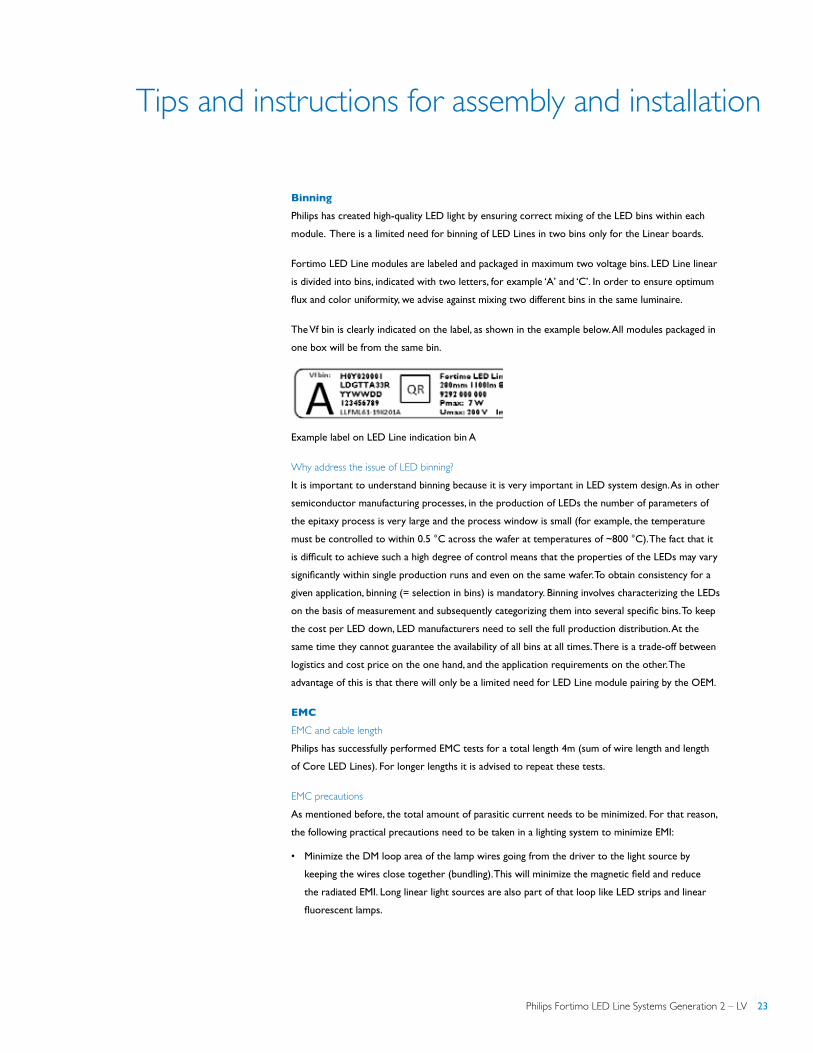
The Vf bin is clearly indicated on the label, as shown in the example below. All modules packaged in
one box will be from the same bin.
Example label on LED Line indication bin A
Why address the issue of LED binning? It is important to understand binning because it is very important in LED system design. As in other
semiconductor manufacturing processes, in the production of LEDs the number of parameters of
the epitaxy process is very large and the process window is small (for example, the temperature
must be controlled to within 0.5 °C across the wafer at temperatures of ~800 °C). The fact that it
is difficult to achieve such a high degree of control means that the properties of the LEDs may vary
significantly within single production runs and even on the same wafer. To obtain consistency for a
given application, binning (= selection in bins) is mandatory. Binning involves characterizing the LEDs
on the basis of measurement and subsequently categorizing them into several specific bins. To keep
the cost per LED down, LED manufacturers need to sell the full production distribution. At the
same time they cannot guarantee the availability of all bins at all times. There is a trade-off between
logistics and cost price on the one hand, and the application requirements on the other. The
advantage of this is that there will only be a limited need for LED Line module pairing by the OEM.
EMC
EMC and cable length Philips has successfully performed EMC tests for a total length 4m (sum of wire length and length
of Core LED Lines). For longer lengths it is advised to repeat these tests.
EMC precautions As mentioned before, the total amount of parasitic current needs to be minimized. For that reason,
the following practical precautions need to be taken in a lighting system to minimize EMI:
• Minimize the DM loop area of the lamp wires going from the driver to the light source by
keeping the wires close together (bundling). This will minimize the magnetic field and reduce
the radiated EMI. Long linear light sources are also part of that loop like LED strips and linear
fluorescent lamps.
24 Philips Fortimo LED Line Systems Generation 2 – LV
Tips and instructions for assembly and installation
• Minimize the CM parasitic capacitance of the output wiring + light source to earth by keeping
the length of the wires between driver and light source as short as possible. Also minimize the
copper cooling area on the LED PCB and keep the length of the incoming mains wire inside the
luminaire as short as possible.
• Keep mains and control wires(DALI, 0-10V) separated from the output wires (do not bundle).
• Ground the lighting system chassis and other internal metal parts to earth (class I luminaires)
and do not let large metal parts “float”. Always use the safety or functional earth connector
or wire from the lamp driver. Or use equipotential connecting wires for all internal floating
metal parts which are inaccessable (class II luminaires). Keep safety and functional earth wires
as short as possible to minimize their inductance, use as much as possible large metal areas
(chassis, mounting plates, brackets) for earthing purposes instead.
• Sometimes, radiated EMC compliance cannot be achieved, necessitating the use of a 100 … 300Ω
axial ferrite bead(s) for either mains or lamp wiring (effective for interference between 30MHz
and 300MHz).
Adhering to these rules will in general result in EMC compliance. If not, the Philips Lighting
Design-In team can be consulted for a posible solution.
Electrostatic discharge (ESD)
Introduction to ESD
It is generally recognized that ElectroStatic Discharge (ESD) can damage electronic components,
like LED chips, resulting in early failures. Professional users of electronic components are used to
implement extensive and disciplined measures to avoid ESD damage in their finished end products.
Now, with the introduction of LED components for lighting, a new breed of users, such as OEM’s
and installers, are exposed to handling and manufacturing with LED electronic components.
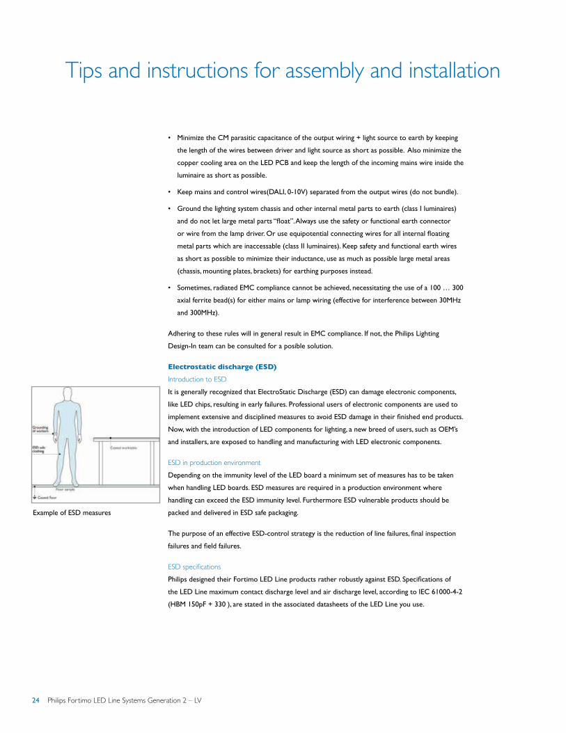
ESD in production environmentDepending on the immunity level of the LED board a minimum set of measures has to be taken
when handling LED boards. ESD measures are required in a production environment where
handling can exceed the ESD immunity level. Furthermore ESD vulnerable products should be
packed and delivered in ESD safe packaging.
The purpose of an effective ESD-control strategy is the reduction of line failures, final inspection
failures and field failures.
ESD specificationsPhilips designed their Fortimo LED Line products rather robustly against ESD. Specifications of
the LED Line maximum contact discharge level and air discharge level, according to IEC 61000-4-2
(HBM 150pF + 330Ω), are stated in the associated datasheets of the LED Line you use.
Example of ESD measures
Philips Fortimo LED Line Systems Generation 2 – LV 25
Tips and instructions for assembly and installation
Controllability
Servicing and installing luminairesIt is highly recommend informing installers not to touch the LED components and use earthed
arm-straps to avoid ESD damage during installation and maintenance.
ESD consultancyIndependent ESD consultancy companies can advise and supply adequate tools and
protection guidance.
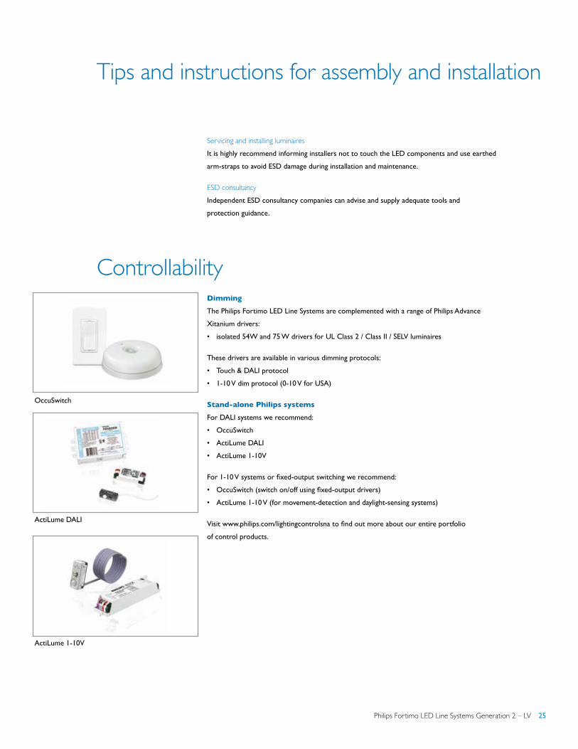
Dimming
The Philips Fortimo LED Line Systems are complemented with a range of Philips Advance
Xitanium drivers:
• isolated 54W and 75 W drivers for UL Class 2 / Class II / SELV luminaires
These drivers are available in various dimming protocols:
• Touch & DALI protocol
• 1-10 V dim protocol (0-10 V for USA)
Stand-alone Philips systems
For DALI systems we recommend:
• OccuSwitch
• ActiLume DALI
• ActiLume 1-10V
For 1-10 V systems or fixed-output switching we recommend:
• OccuSwitch (switch on/off using fixed-output drivers)
• ActiLume 1-10 V (for movement-detection and daylight-sensing systems)
Visit www.philips.com/lightingcontrolsna to find out more about our entire portfolio
of control products.
OccuSwitch
ActiLume DALI
ActiLume 1-10V
26 Philips Fortimo LED Line Systems Generation 2 – LV
Compliance and approval
Chemical compatibility
In the market medium power LEDs exist containing a silver (Ag)-finished Lead frame. The lead
frame finish is sensitive to corrosion when exposed to substances containing Sulfur or Chlorine. In
that case parts of the lead frame may blacken, which will impair the Lumen Output or the color of
the LED. Materials that are known to have a higher risk to be a source of Sulfur and Chlorine are
for example natural rubber or corrugated paper.
We recommend ensuring that the direct environment of these LEDs in the luminaire does not
contain materials that can be a source of Sulfur or Chlorine, for optimal reliability of the LED, LED
module and/or LED luminaire. Furthermore, make sure that the products with these LEDs are not
stored or used in vicinity of sources of Sulfur or Chlorine, and the production environment is also
free of these materials. Also avoid cleaning of the LED products with these types of LEDs with
abrasive substances, brushes or organic solvents like Acetone and TCE.
The Fortimo LED Line uses LEDs with above explained type of lead frame.
Therefore above recommendations apply for the Fortimo LED Line modules.
Philips Fortimo LED Line Systems comply with the standards shown below.
Compliance and approval marks
The Fortimo LED Line family is ENEC approved and comply with CE regulations. The relevant
standards are summarized in the table below. To ensure luminaire approval, the conditions of
acceptance need to be fulfilled. Details can be requested from your local sales representative. All
luminaire manufacturers are advised to conform to the international standards of luminaire design
(IEC 60598-Luminaires).
IP rating, humidity and condensation
The Fortimo LED Line systems are build-in systems and therefore have no IP classification. They are
not designed for operation in the open air. The OEM is responsible for proper IP classification and
approbation of the luminaire.
The Fortimo LED Line has been developed and released for use in damp locations but not for
locations where condensation is present. If there is a possibility that condensation could come into
contact with the modules, the system/luminaire builder must take precautions to prevent this.
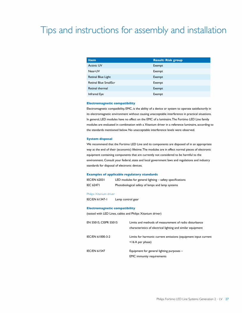
Photobiological safety
The lamp standard, IEC 62471 ‘Photobiological safety of lamps and lamp systems’ gives guidance
on evaluating the photobiological safety of lamps and lamp systems including luminaires. It
specifically defines the exposure limits, reference measurement technique and classification
scheme for the evaluation and control of photobiological hazards from all electrically powered
incoherent broadband sources of optical radiation, including LEDs, in the wavelength range from
200 nm to 3000 nm. Measurement results for LED Line products are given below. Based on these
measurements, no additional safety measures have been included.
Philips Fortimo LED Line Systems Generation 2 – LV 27
Tips and instructions for assembly and installation
Electromagnetic compatibility
Electromagnetic compatibility, EMC, is the ability of a device or system to operate satisfactorily in
its electromagnetic environment without causing unacceptable interference in practical situations.
In general, LED modules have no effect on the EMC of a luminaire. The Fortimo LED Line family
modules are evaluated in combination with a Xitanium driver in a reference luminaire, according to
the standards mentioned below. No unacceptable interference levels were observed.
System disposal
We recommend that the Fortimo LED Line and its components are disposed of in an appropriate
way at the end of their (economic) lifetime. The modules are in effect normal pieces of electronic
equipment containing components that are currently not considered to be harmful to the
environment. Consult your federal, state and local government laws and regulations and industry
standards for disposal of electronic devices.
Examples of applicable regulatory standards
IEC/EN 62031 LED modules for general lighting – safety specifications
IEC 62471 Photobiological safety of lamps and lamp systems
Philips Xitanium driverIEC/EN 61347-1 Lamp control gear
Electromagnetic compatibility
(tested with LED Lines, cables and Philips Xitanium driver)
EN 55015, CISPR 55015 Limits and methods of measurement of radio disturbance
characteristics of electrical lighting and similar equipment
IEC/EN 61000-3-2 Limits for harmonic current emissions (equipment input current
<16 A per phase)
IEC/EN 61547 Equipment for general lighting purposes –
EMC immunity requirements
Item Result: Risk group
Actinic UV Exempt
Near-UV Exempt
Retinal Blue Light Exempt
Retinal Blue SmallScr Exempt
Retinal thermal Exempt
Infrared Eye Exempt
© 2013 Koninklijke Philips N.V.
All rights reserved. Specifications are subject to change without notice.
Form no. LE-6550-B
Philips Lighting Company A Division of Philips North America
10275 W. Higgins Road Rosemont, IL 60018 Tel: 800-322-2086 Fax: 888-423-1882 Cuxstomer Support/Customer Care: 800-372-3331www.philips.com/ledmodulesna
Compliance and approval
EnvironmentalThe product is compliant with European Directive 2002/95/EC of January 2003 on Restriction of
the Use of Certain Hazardous Substances in Electrical and Electronic Equipment (RoHS)*.
Cautions during storage and transportation
When storing this product for for more than one week
• Store in a dark place. Do not expose to sunlight.
• For Fortimo LED Line: maintain
- temperature between -40..+85 °C
- RH 5..85 %.
• For LED Line Cover 2ft soft-diffuse: maintain
- temperature between -40..+75 °C
- RH 5..85 %.
During transportation and storage for a short time• Maintain temperature below 100 °C at normal humidity.
Philips Fortimo LED Line Systems Gen 2 must be operated within the specifications found in
the product sheets and Design In Guide. Please consult your local Philips Representative for
additional information.
* Restrictions on Hazardous Substances (RoHS) is a European directive (2002/95/EC) designed to limit the content of 6 substances [lead, mercury, cadmium, hexavalent chromium, polybrominated biphenyls (PBB), and polybrominated diphenyl ethers (PBDE)] in electrical and electronic products. For products used in North America compliance to RoHS is voluntary and self-certified.