Embed Size (px)
Citation preview
DESIGN, INSTALLATION, AND COMMISSIONING RESULTS FOR SUPPRESSING ROGUE TE MODES IMPACTING VERTICAL BPM
READINGS OF THE APS STORAGE RING* R. Lill, G. Decker, J. Hoyt, X. Sun, B. Yang
Advanced Photon Source, Argonne National Laboratory, Argonne, IL 60439
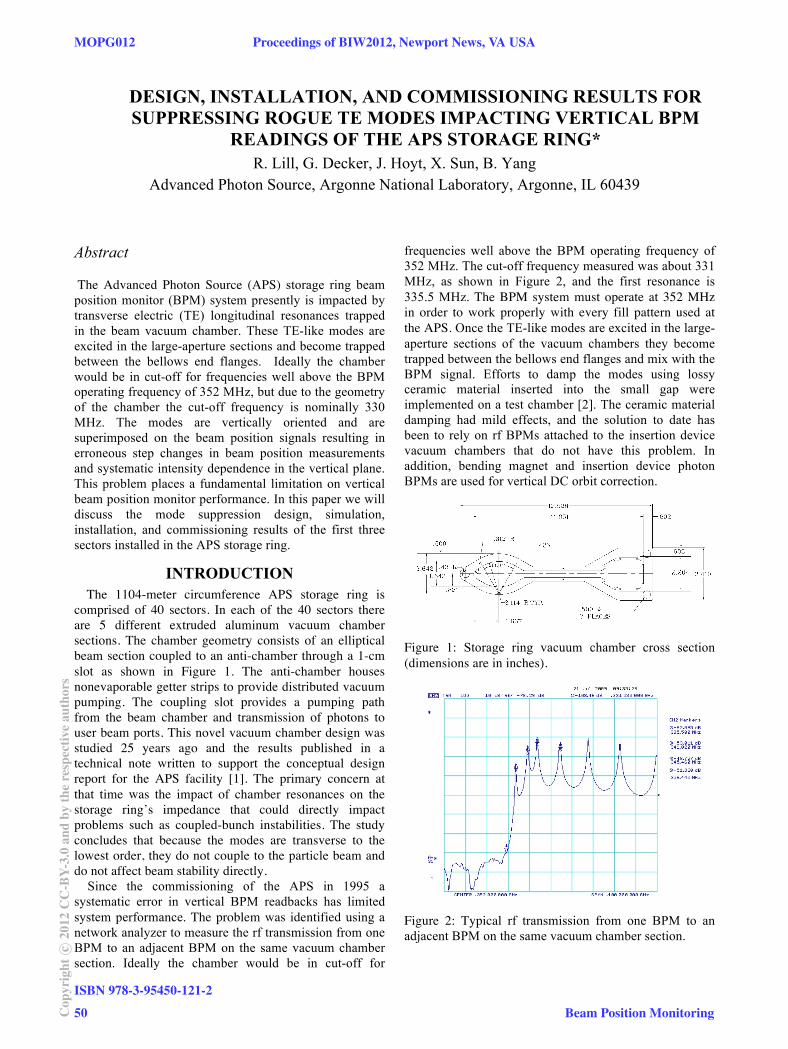
Abstract The Advanced Photon Source (APS) storage ring beam position monitor (BPM) system presently is impacted by transverse electric (TE) longitudinal resonances trapped in the beam vacuum chamber. These TE-like modes are excited in the large-aperture sections and become trapped between the bellows end flanges. Ideally the chamber would be in cut-off for frequencies well above the BPM operating frequency of 352 MHz, but due to the geometry of the chamber the cut-off frequency is nominally 330 MHz. The modes are vertically oriented and are superimposed on the beam position signals resulting in erroneous step changes in beam position measurements and systematic intensity dependence in the vertical plane. This problem places a fundamental limitation on vertical beam position monitor performance. In this paper we will discuss the mode suppression design, simulation, installation, and commissioning results of the first three sectors installed in the APS storage ring.
INTRODUCTION The 1104-meter circumference APS storage ring is
comprised of 40 sectors. In each of the 40 sectors there are 5 different extruded aluminum vacuum chamber sections. The chamber geometry consists of an elliptical beam section coupled to an anti-chamber through a 1-cm slot as shown in Figure 1. The anti-chamber houses nonevaporable getter strips to provide distributed vacuum pumping. The coupling slot provides a pumping path from the beam chamber and transmission of photons to user beam ports. This novel vacuum chamber design was studied 25 years ago and the results published in a technical note written to support the conceptual design report for the APS facility [1]. The primary concern at that time was the impact of chamber resonances on the storage ring’s impedance that could directly impact problems such as coupled-bunch instabilities. The study concludes that because the modes are transverse to the lowest order, they do not couple to the particle beam and do not affect beam stability directly. Since the commissioning of the APS in 1995 a systematic error in vertical BPM readbacks has limited system performance. The problem was identified using a network analyzer to measure the rf transmission from one BPM to an adjacent BPM on the same vacuum chamber section. Ideally the chamber would be in cut-off for
frequencies well above the BPM operating frequency of 352 MHz. The cut-off frequency measured was about 331 MHz, as shown in Figure 2, and the first resonance is 335.5 MHz. The BPM system must operate at 352 MHz in order to work properly with every fill pattern used at the APS. Once the TE-like modes are excited in the large-aperture sections of the vacuum chambers they become trapped between the bellows end flanges and mix with the BPM signal. Efforts to damp the modes using lossy ceramic material inserted into the small gap were implemented on a test chamber [2]. The ceramic material damping had mild effects, and the solution to date has been to rely on rf BPMs attached to the insertion device vacuum chambers that do not have this problem. In addition, bending magnet and insertion device photon BPMs are used for vertical DC orbit correction.
Figure 1: Storage ring vacuum chamber cross section (dimensions are in inches).
Figure 2: Typical rf transmission from one BPM to an adjacent BPM on the same vacuum chamber section.
MOPG012 Proceedings of BIW2012, Newport News, VA USA
ISBN 978-3-95450-121-2
50Cop
yrig
htc ○
2012
CC
-BY-
3.0
and
byth
ere
spec
tive
auth
ors
Beam Position Monitoring

MODE SUPPRESSOR DESIGN Simulations have been conducted on various models of the extruded vacuum chamber and associated components using CST Microwave Studio [3]. The largest source of these rogue modes was found to be the photon absorbers. The photon absorber located at the downstream end of the chamber is designed to absorb the remaining non-user synchrotron radiation. This is necessary in order to minimize the number of photons striking the wall of the vacuum chamber. The absorber and associated pumping components result in discontinuities in the vacuum chamber cross section geometry. The rf impedance of these discontinuities is minimized but not eliminated by the installation of screens that match the contour of the vacuum chamber. The screens allow the gases generated at the absorber to be pumped. The TE-like modes that are excited in the absorber section become trapped between the bellows end flanges. Simulations show the modes generated from the absorber propagate down the chamber and resonate. The modes are vertically oriented and are superimposed on the beam position signals. These mixed signals change not only with beam position but also with any change in the rogue signals. The absorber presents the main source for generating TE-like modes that are trapped in the vacuum chamber.
Snubber The basic idea is to short the small-gap region closest
to the antechamber to avoid intercepting stray x-rays and to increase the chamber cut-off frequency above the BPM operating frequency [4]. The mode suppressor or snubber is designed to provide a low impedance path from the top to the bottom of the vacuum chamber. This is accomplished using an off-the-shelf beryllium copper longitudinal grounding strip to short the high-field area of the chamber. The snubbers can slide into the end of the chamber and be positioned in the small-gap region shown in Figure 3. Beryllium copper has excellent spring-like features and is resistant to compression set. The beryllium copper grounding strips are mounted in stainless steel carriers that can be linked together. The snubber system effectively alters the geometry of the vacuum chamber by periodically shorting the high-field region in the small gap.
The installation of the snubber system provides very repeatable results, shown in Figure 4. The vacuum chamber cut-off frequency is increased from approximately 330 MHz to 440 MHz by periodically shorting the small-gap areas. The simulated results for a simplified straight chamber and the measured results of a curved chamber with snubbers show good agreement.
The most critical design requirement for implementing the mode suppressor is that the shorting device does not intercept the x-ray beam. The installation must be accomplished by accessing the vacuum flanges on each end of the chamber. The snubber system had to be installed similar to the getter strips, which slide in tracks along the antechamber shown in Figure 1 of the chamber
cross section in Figure 1. It was critical that the installation of these snubber circuits did not damage the chamber.
Figure 3: Storage ring vacuum chamber cross section with standard snubbers installed.
Figure 4: The simulated results in a straight simplified chamber, and the measured results of a curved chamber with eight snubbers installed.
The two curved chambers in each sector present a new challenge requiring a special curved type snubber. Installing standard snubbers at the downstream end of the chamber could not be implemented because the snubber would be intercepted by x-rays. The solution was the design of a “C” snubber that allowed installation of the snubber closer to the BPM at the end of the chamber. This appears to be a good trade-off of acceptable performance over the complexity required to design a more robust stick absorber that is water cooled for two out of the nine BPMs in each sector.
Proceedings of BIW2012, Newport News, VA USA MOPG012
Beam Position Monitoring
ISBN 978-3-95450-121-2
51 Cop
yrig
htc ○
2012
CC
-BY-
3.0
and
byth
ere
spec
tive
auth
ors

INSTALLATION Installation is similar to installing the vacuum chamber
getter strips. To determine the installation locations of the snubbers, careful ray tracing and simulations for each chamber under worst-case steering conditions had to be studied. Each chamber has a prescribed number of snubbers and a set location that is fixed by the coupling straps between each snubber. Figure 5 illustrates a curved chamber with the x-ray fan shown with eight standard and two curved snubbers installed. Each of the five chambers were analyzed, and a complete drawing package was generated.
The installation must be accomplished by accessing the vacuum flanges. Each snubber is inserted into the chamber one at a time and linked to the next snubber with a connecting strap. This installation is similar to the getter strips, which slide in tracks along the antechamber shown in Figure 1. There are a total of five tracks in the antechamber, but only two are presently being used. This facilitates the use of the inside tracks closest to the small gap. It is critical that the installation of these snubber circuits can be accomplished in the extremely confined spaces between adjacent vacuum chamber sections.
Figure 5: Storage ring vacuum chamber section 4 with snubbers installed and ray tracing.
COMMISSIONING RESULTS A single bunch storage ring fill was used because of its extremely simple spectrum. This fill pattern generates a series of uniformly spaced spectral lines of equal amplitude, with 271-kHz spacing (the APS revolution frequency). The four button signals are fed into a hybrid comparator and the vertical difference signal is derived. This signal is then bandpassed with a center frequency of 352 MHz with 10 MHz, -3 dB bandwidth. The hybrid comparator and bandpass filter form the front-end components for the monopulse BPM system. The data set shown in Figure 6 shows three different sectors of BPMs for the more problematic curved chambers. The top plot of S1:AP4 does not have the snubbers installed. The most notable difference is the spurious response at the center frequency of 352 MHz. The degree to which the spectral lines in the broadband data differ in amplitude is a measure of the impact of the chamber resonance. The lower two plots of S2:AP4 and S3:AP4 show a smoother in-band response. The shape of the response is largely due to the bandpass filter response. The spurious response in the center 10-MHz frequency bandwidth is responsible
for erratic BPM behavior and was substantially suppressed or eliminated.
Figure 6: Curved chamber section 4 comparing three different sectors without and with snubbers installed.
CONCLUSION The snubber suppression system has been installed in sectors 3, 4, and 29 of the APS storage ring as of January 2012. The snubber design will reduce or eliminate the trapped TE-like mode resonances in the APS storage ring vacuum chambers. The snubber system is an inexpensive solution to a problem that has limited the APS vertical beam stability. The plan at this time is to accelerate the installation schedule to up to six sectors per year. It is hopeful that the benefit from this installation will be improved beam stablity for the APS upgrade.
REFERENCES [1] R. Kustom J. Cook, “Electromagnetic Properties of
the Vacuum Chamber”, APS Light Source Note, LS-56 (1986).
[2] Y. Kang, G. Decker, and J. Song, “Damping Spurious Harmonic Resonances in the APS Storage Ring Beam Chamber,” PAC ’99, New York, NY March 1999, THP61, p. 3092 (1999); http://www.JACoW.org
[3] CST Studio Suite 2012, Computer Simulation Technology, www.cst.com.
[4] R. Lill, G. Decker, J. Hoyt, X. Sun, “Measurement, Simulation, and Suppression of APS Storage Ring Vacuum Chamber TE Modes Impacting Vertical BPM Readings”, BIW10, TUPSM049, P.260 (2010); http://www.JACoW.org
The submitted manuscript has been created by UChicago Argonne, LLC, Operator of Argonne National Laboratory (“Argonne”). Argonne, a U.S. Department of Energy Office of Science laboratory, is operated under Contract No. DE-AC02-06CH11357. The U.S. Government retains for itself, and others acting on its behalf, a paid-up nonexclusive, irrevocable worldwide license in said article to reproduce, prepare derivative works, distribute copies to the public, and perform publicly and display publicly, by or on behalf of the Government.
MOPG012 Proceedings of BIW2012, Newport News, VA USA
ISBN 978-3-95450-121-2
52Cop
yrig
htc ○
2012
CC
-BY-
3.0
and
byth
ere
spec
tive
auth
ors
Beam Position Monitoring


![Installation Manual-System Commissioning [ cBSC6600 ]](https://img.pdfslide.net/doc/110x75/553d62d14a795968288b4673/installation-manual-system-commissioning-cbsc6600-.jpg)