Embed Size (px)
Citation preview
© 2017 IJRTI | Volume 2, Issue 4 | ISSN: 2456-3315
IJRTI1704003 International Journal for Research Trends and Innovation (www.ijrti.org) 7
Design & Interface of Voice Module for Deaf and Dumb
1Ch. Naveen,
2J.Kavya Sree,
3V. Raghu Charan,
4CH. Manoj,
5R. Kumara Swamy
1,2,3,4
Research Scholar, 5Assistant Professor
Dept. of E.C.E, NSRIT College of Engineering
Sontyam, Visakhapatnam
Abstract- The objective of this paper is to build a device
that can be controlled by gesture. User is able to control
motions of the device by moving the controller and
performing predefined gestures. This paper provides a
basic platform for many potential applications such as
military, gesture human-machine interfacing, etc. This
paper is used for physically disabled and old people to
operate the device through gestures. This can be done by
using accelerometer i.e, based on MEMS technology. For
this paper, AT89S52 microcontroller and accelerometer
module, speakers is used. This device helps deaf and dumb
people to announce their requirements. By this the person
who is near can understand their need and help them. This
saves the time to understand each other and ease in
communication. However, Recognizing the sign or gesture
once it has been captured is much more challenging,
especially in a Continuous stream. In fact currently, this is
the focus of the research.
Keywords:-micro-controller, accelerometer, embedded
system.
I. INTRODUCTION
Embedded systems are a system, which performs a
specific or a pre-defined task. It is the combinations of
hardware and software. It is a programmable hardware design
nothing but an electronic chip.A general-purpose definition of
embedded systems is that they are devices used to control,
monitor or assist the operation of equipment, machinery or
plant. ―Embedded‖ reflects the fact that they are an integral
part of the system. At the other extreme a general-purpose
computer may be used to control the operation of a large complex processing systems.All embedded systems include
microprocessors. Some of these computers are however very
simple systems as compared with a personal computer. The
very simplest embedded systems are capable of performing
only single functions to meet a single predetermined purpose.
In some cases a microprocessor may be designed in
such way that application software for a particular purpose can
be added to the basic software in a second process, after which
it is not possible to make further changes. The applications
software on such processors is sometimes referred to as
firmware. The simplest devices consist of a single
microprocessor (often called a ―chip‖), which may itself be packaged with other chips in a hybrid systems or Application
Specific Integrated Circuit
(ASIC). Its input comes from a detector or sensor and its
output goes to a switch or an activator which (for example)
may start or stop the operation of a machine or, operating a
value, may control the flow of fuel to an engine.
Fig. 1. Types of Embedded Systems
II. OVERVIEW OF EMBEDDED SYSTEM
ARCHITECTURE
Every embedded system consists of custom-built
hardware built around a Central Processing Unit (CPU). This
hardware also contains memory chips onto which the software
is loaded. The software residing on the memory chip is also
called the ‗firmware‘.
The operating system runs above the hardware, and
the application software runs above the operating system. The
same architecture is applicable to any computer including a
desktop computer. For applications involving complex
processing, it is advisable to have an operating system. In such
a case, you need to integrate the application software with the
operating system and then transfer the entire software on to the memory chip. Once the software is transferred to the memory
chip, the software will continue to run for a long time you
don‘t need to reload new software.
The details of the various building blocks of the
hardware of an embedded system. As shown in Fig.1. the
building blocks are:
Central Processing Unit (CPU)
Memory (Read-only Memory and Random Access Memory)
Input Devices
Output devices
Communication interfaces
Application-specific circuitry
III. HARDWARE REQUIREMENTS
Microcontroller AT89C51.
© 2017 IJRTI | Volume 2, Issue 4 | ISSN: 2456-3315
IJRTI1704003 International Journal for Research Trends and Innovation (www.ijrti.org) 8
Accelerometer.
LED array.
Voice Module
Switching Mode.
Crystal Oscillator.
Liquid Crystal Display. Speakers.
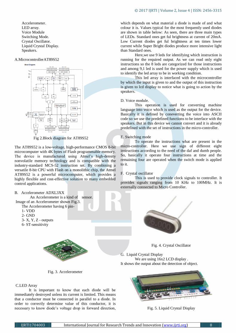
A.MicrocontrollerAT89S52
Fig 2.Block diagram for AT89S52
The AT89S52 is a low-voltage, high-performance CMOS 8-bit
microcomputer with 4K bytes of Flash programmable memory.
The device is manufactured using Atmel‘s high-density
nonvolatile memory technology and is compatible with the
industry-standard MCS-52 instruction set. By combining a
versatile 8-bit CPU with Flash on a monolithic chip, the Atmel
AT89S52 is a powerful microcomputer, which provides a
highly flexible and cost-effective solution to many embedded
control applications.
B. Accelerometer ADXL3XX An Accelerometer is a kind of sensor.
Image of an Accelerometer shown Fig.3.
The Accelerometer having 6 pin-
1- VDD
2- GND
3- X, Y, Z - outputs
6- ST-sensitivity
Fig. 3. Accelerometer
C.LED Array
It is important to know that each diode will be immediately destroyed unless its current is limited. This means
that a conductor must be connected in parallel to a diode. In
order to correctly determine value of this conductor, it is
necessary to know diode‘s voltage drop in forward direction,
which depends on what material a diode is made of and what
colour it is. Values typical for the most frequently used diodes
are shown in table below: As seen, there are three main types
of LEDs. Standard ones get ful brightness at current of 20mA.
Low Current diodes get ful brightness at ten times lower
current while Super Bright diodes produce more intensive light than Standard ones.
Here,we use 9 leds for identifying which instruction is
running for the required output. As we can read only eight
instructions so the 8 leds are categorized for those instructions
and among 9,1 led is used for the power supply which is used
to identify the led array to be in working condition.
This led array is interfaced with the microcontroller
by which the input is given to and the output of this instruction
is given to lcd display to notice what is going to action by the
speakers.
D. Voice module. This operation is used for converting machine
language into voice which is used as the output for the device.
Basically it is defined by coneverting the voice into ASCII
code so we use the predefined functions to be interface with the
speakers. But in this device we cannot convert and it is already
predefined with the set of instructions in the micro-controller.
E. Switching mode
To operate the instructions what are present in the
micro-controller. Here we use sign of different eight
instructions according to the need of the daf and dumb people. So, basically it operate four instructions at time and the
remaining four are operated when the switch mode is applied
to it.
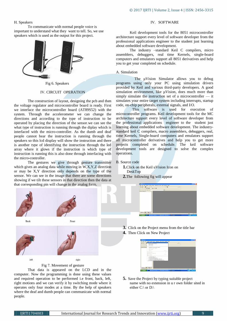
F. Crystal oscillator
This is used to provide clock signals to controller. It
provides signals ranging from 10 KHz to 100MHz. It is
externally connected to Micro Controller.
Fig. 4. Crystal Oscillator
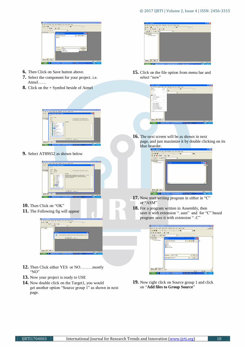
G. Liquid Crystal Display
We are using 16x2 LCD display .
It shows the output about the detection of object.
Fig. 5. Liquid Crystal Display
© 2017 IJRTI | Volume 2, Issue 4 | ISSN: 2456-3315
IJRTI1704003 International Journal for Research Trends and Innovation (www.ijrti.org) 9
H. Speakers
To communicate with normal people voice is
important to understand what they want to tell. So, we use
speakers which is used as the output for this project.
Fig 6. Speakers
IV. CIRCUIT OPERATION
The construction of layout, designing the pcb and then
the voltage regulator and microcontroller board is ready. First
we interface the microcontroller board (AT89S52) with the
system. Through the accelerometer we can change the
directions and according to the type of instruction to be
operated by placing the direction of the sensor.we can see the
what type of instruction is running through the diplay which is
interfaced with the micro-controller. As the dumb and deaf
people cannot hear the instruction is running through the
speakers so this lcd display will show the instruction and there
is another type of identifying the instruction through the led array where it glows if the instruction is which type of
instruction is running this is also done through interfacing with
the micro-controller.
The gestures we give through gesture transmitter
which gives an analog data while moving in W,X,Y,Z direction
or may be X,Y direction only depends on the type of the
sensor. We can see in the image that there are some directions
showing if we tilt these sensors in that direction then the data at
that corresponding pin will change in the analog form.
Fig 7. Movement of gesture
That data is appeared on the LCD and in the
computer. Now the programming is done using these values
and required operation to be performed i.e front, back, left,
right motions and we can verify it by switching mode where it
operates only four modes at a time. By the help of speakers
where the deaf and dumb people can communicate with normal
people.
IV. SOFTWARE
Keil development tools for the 8051 microcontroller
architecture support every level of software developer from the
professional applications engineer to the student just learning
about embedded software development.
The industry –standard Keil C compilers, micro
assemblers, debuggers, real time Kernels, single-board
computers and emulators support all 8051 derivatives and help
you to get your completed on schedule.
A. Simulation
The µVision Simulator allows you to debug programs using only your PC using simulation drivers
provided by Keil and various third-party developers. A good
simulation environment, like µVision, does much more than
simply simulate the instruction set of a microcontroller — it
simulates your entire target system including interrupts, startup
code, on-chip peripherals, external signals, and I/O.
This software is used for execution of
microcontroller programs. Keil development tools for the MC
architecture support every level of software developer from
the professional applications engineer to the student just
learning about embedded software development. The industry-
standard keil C compilers, macro assemblers, debuggers, real, time Kernels, Single-board computers and emulators support
all microcontroller derivatives and help you to get more
projects completed on schedule. The keil software
development tools are designed to solve the complex
operations.
B. Source code
1.Click on the Keil uVision Icon on
DeskTop
2.The following fig will appear
3. Click on the Project menu from the title bar
4. Then Click on New Project
5. Save the Project by typing suitable project
name with no extension in u r own folder sited in
either C:\ or D:\
© 2017 IJRTI | Volume 2, Issue 4 | ISSN: 2456-3315
IJRTI1704003 International Journal for Research Trends and Innovation (www.ijrti.org) 10
6. Then Click on Save button above.
7. Select the component for your project. i.e.
Atmel……
8. Click on the + Symbol beside of Atmel
9. Select AT89S52 as shown below
10. Then Click on ―OK‖
11. The Following fig will appear
12. Then Click either YES or NO………mostly ―NO‖
13. Now your project is ready to USE
14. Now double click on the Target1, you would
get another option ―Source group 1‖ as shown in next
page.
15. Click on the file option from menu bar and
select ―new‖
16. The next screen will be as shown in next
page, and just maximize it by double clicking on its blue boarder.
17. Now start writing program in either in ―C‖
or ―ASM‖
18. For a program written in Assembly, then save it with extension ―. asm‖ and for ―C‖ based
program save it with extension ― .C‖
19. Now right click on Source group 1 and click on ―Add files to Group Source‖
© 2017 IJRTI | Volume 2, Issue 4 | ISSN: 2456-3315
IJRTI1704003 International Journal for Research Trends and Innovation (www.ijrti.org) 11
20. Now you will get another window, on which by default ―C‖ files will appear.
21. Now select as per your file extension given
while saving the file
22. Click only one time on option ―ADD‖
23. Now Press function key F7 to compile. Any
error will appear if so happen.
24. If the file contains no error, then press
Control+F5 simultaneously.
25. The new window is as follows
26. Then Click ―OK‖
27. Now Click on the Peripherals from menu bar, and check your required port as shown in fig
below
28. Drag the port a side and click in the program
file.
29. Now keep Pressing function key ―F11‖
slowly and observe.
30. You are running your program successfully.
VI. CONCLUSION
The output we required is, whenever the hand gesture
is moved forward, backward, left or right according type of
situation or the need of the dumb and deaf people and hand
gesture is kept back, the switch is operated to another where
different instructions are activated. If any delayed in operating
the device we can use reset the coding and it comes to first,
when another instruction is applied.
VII. FUTURE SCOPE Furtherly this system can be implemented by performing
multiple operations using a 3Dimensional axis of
Accelerometer and this can be taken into
most advanced technology such as Nano-electromechanical
system which are very small in size that is in terms of
nanometers.
REFERENCES
1.―The 8051 Microcontroller and Embedded
S ys t e m s ‖ B y M u h a m m a d A l i Mazidiand Janice Gillespie Mazidi.Pearson Education.
2. Embedded system by Raj Kamal.
3. 8051 microcontroller and embedded systems by Mazzidi.
4. Venketraman.s,T.V.Padmavathi ―speech for the
Disabled‖ volume 118,page 13
5. John kangchun perng,Seth, Hollar‖Acceleration
sensor‖.
6. Salman afghani,‖Microcontroller and sensors based
gesture vocaliser‖ APR 9600. Copyright © 2016
7. Analog Devices, Norwood, MA,
http://www.analog.com


![ENG48-0302 Experiences VGR - Amazon S3 · 2020-02-17 · EXPERIENCES Dearfr…[Blankspotontape—Ed.]Itwasmiracleaftermiracle performed: deaf, dumb, blind, lame, and everything. A](https://img.pdfslide.net/doc/110x75/5ed46ee75e2d82034d643984/eng48-0302-experiences-vgr-amazon-s3-2020-02-17-experiences-dearfrblankspotontapeaeditwasmiracleaftermiracle.jpg)