Embed Size (px)
Citation preview

1558-1748 (c) 2018 IEEE. Personal use is permitted, but republication/redistribution requires IEEE permission. See http://www.ieee.org/publications_standards/publications/rights/index.html for more information.
This article has been accepted for publication in a future issue of this journal, but has not been fully edited. Content may change prior to final publication. Citation information: DOI 10.1109/JSEN.2018.2814839, IEEE SensorsJournal
1
Design, Modeling, and Validation of a SoftMagnetic 3-D Force Sensor
Anany Dwivedi, Anand Ramakrishnan, Aniketh Reddy, Kunal Patel, Selim Ozel, Cagdas D. Onal
Abstract—Recent advances in robotics promise a future whererobots co-exist and collaborate with humans in unstructuredenvironments, which will require frequent physical interactionswhere accurate tactile information will be crucial for perfor-mance and safety. This article describes the design, fabrication,modeling, and experimental validation of a soft-bodied tactilesensor that accurately measures the complete 3-D force vectorfor both normal and shear loading conditions. Our researchconsiders the detection of changes in the magnetic field vectordue to the motion of a miniature magnet in a soft substrateto measure normal and shear forces with high accuracy andbandwidth. The proposed sensor is a pyramid-shaped tactileunit with a tri-axis Hall element and a magnet embedded ina silicone rubber substrate. The non-linear mapping between the3-D force vector and the Hall effect voltages is characterized bytraining a neural network. We validate the proposed soft forcesensor over static and dynamic loading experiments and obtain amean absolute error below 11.7 mN or 2.2% of the force range.These results were obtained for a soft force sensor prototype andloading conditions not included in the training process, indicatingstrong generalization of the model. To demonstrate its utility,the proposed sensor is used in a force-controlled pick-and-placeexperiment as a proof-of-concept case study.
I. INTRODUCTION
Direct force and tactile sensing remains an open technicalproblem in robotics [1]–[3]. To address this problem, newsensing mechanisms and modeling approaches need to be de-veloped to achieve compliant, safe, and aware interactions be-tween robots, human users, and the environment. We observethree fundamental challenges that impede progress [4]. First,it is difficult to obtain a reliable sensing modality betweenexternal forces and a measurable change in a physical medium,without detrimental nonlinearities or other artifacts such ashysteresis or time delay. Second, modeling to obtain a reliablemap between the external force and the measured physicalchange is challenging, especially for multi-dimensional mea-surements. Finally, scalability tends to be a challenge, toobtain useful spatial resolution over a surface, while avoidingcrosstalk between sensing elements. This article adresses eachchallenge by presenting a magnetic sensing modality andneural network based modeling of a small tri-axial soft sensingelement.
This material is based upon work supported by the National ScienceFoundation (NSF) under Grant No. CNS-1544636. Any opinions, findings,and conclusions or recommendations expressed in this material are those ofthe authors and do not necessarily reflect the views of the NSF.
The authors are with the WPI Soft Robotics Laboratory, MechanicalEngineering Department and Robotics Engineering Program, Worcester Poly-technic Institute, MA 01609, USA. All correspondence should be addressedto Cagdas Onal [email protected]
Anany Dwivedi and Anand Ramakrishnan contributed equally to this work.
Fig. 1: 1) Design of the proposed tri-axial soft force sensor utilizesa miniature magnet (A), Hall Effect IC (B), and a circuit layer onan acrylic sheet (C), embedded in a pyramid shaped silicone rubbersubstrate. 2) The sensor prototype is 8 mm tall with an 12 mm widesquare base.
In terms of sensing medium, tactile sensing literature maybe classified into: 1) stimuli responsive and/or composite mate-rials that mainly employ resistive or capacitive measurements,and 2) using embedded discrete electronic components orother physical quantities such as optical or magnetic signalswithin the sensor body. Resistive sensing has been a popularmethod, although it may suffer from dynamic artifacts [5]–[8]. In [9], Wood et al. uses a conductive fluid (eGaIn) placedin channels created on a soft matrix to measure appliedforces. These are multi-axis force sensors and can measureforces in normal and shear directions. But fabrication usingeGaIn involves a number of challenges which are discussedin [10]. Alternatively, [11] measures pressure (or force) inthe normal direction by the change in capacitance betweentwo PDMS layers filled with carbon nanotubes. A similarmeasurement idea is realized via conductive textiles in [12].In [13] the authors present pressure and position sensors madeof conductive elastomers co-printed into a soft actuator in asingle process without assembly. These sensors are capable ofproviding feedback because of their innovative design and thepiezoresistive effect of conductive elastomers.
On the other hand, in [14], a commercially available baro-metric IC is embedded in a soft elastomer, to perform as a 1-Dtactile sensor to measure normal forces. Yi et al. [15] presentsa tactile sensor using optical fiber Bragg grating based onphase modulation of the optical source to determine the forcesapplied on the sensor. In [8], Sohgawa et al. propose a resistivetactile sensor using piezo-resistive cantilevers embedded in asoft matrix. It is important to note that these existing solutionssuffer from various inherent challenges such as a lack of 3-Dforce sensing capability, relatively complex fabrication andsignal processing circuitry, or hysteresis and time delay.
Regardless of the sensing medium, modeling and obtaininga reliable mapping between the force and the measured physi-
1558-1748 (c) 2018 IEEE. Personal use is permitted, but republication/redistribution requires IEEE permission. See http://www.ieee.org/publications_standards/publications/rights/index.html for more information.
This article has been accepted for publication in a future issue of this journal, but has not been fully edited. Content may change prior to final publication. Citation information: DOI 10.1109/JSEN.2018.2814839, IEEE SensorsJournal
2
cal change is crucial and challenging, especially for multi-axisforce sensing. The work in [16] employs multiphysical finiteelement analysis (FEA) to describe the behavior of a dome-shaped magnetic tactile sensor. Using FEA models are usefulbut in a multiphysics environment small errors and initial set-tings reflect heavily during the actual experimental testing ofthe sensors and since elastomers (e.g. Ecoflex 0030) are knownto be highly nonlinear, FEA modeling is not straightforward.In addition, such models are usually not applicable for real-time computation.
In [9], authors approximate the sensor’s resistance changeresponse as linear and create a calibration matrix using leastmean squares method. A similar approach was taken in [17],where a linear regression model was employed to find therelationship between force applied and the correspondingchange in voltage. The linearity approximation makes thesemodels simple enough to calculate the force mapping in real-time, but they are highly simplistic and thus, prone to errors.Response reliability is also important. In [11], authors mentioncarbon nanotubes not being aligned after repetitive loading.The resulting hysteresis can be reduced by depositing carbonnanotubes at a pre-stretched state, which may increase com-plexity and repeatability issues. These limitations motivated usto consider approaches that use machine learning as a methodfor estimating the complex relationship between the appliedforce and the measured change in the magnetic field vectorin the proposed sensor to offer both accurate modeling andreal-time computation for the nonlinear sensory mapping.
Using an embedded miniature magnet and flexible elec-tronics in a soft substrate, we have previously shown thatsensing local changes in magnetic field is suitable for accurateand high-speed measurements on the curvature of a flexiblebending body [18]. In previous research, our objective wasto obtain curvature measurement from soft silicone rubbersegments for a specific type of bending soft actuator utilizedin a snake robot [19]. This article employs similar designprinciples to force/contact measurements on a soft deformablesubstrate and in a small form factor.
Hall effect based sensors have gained prominence recently[16], [20]–[24]. In [22], Tomo et al. presents a soft sensorwhich utilizes a magnet for detecting forces in multiple axes.16 Hall-effect ICs are used in total for one sensor module,hence adding to the complexity of the design. In this work,we present accurate force measurement results using a singleIC with a magnet on top. We also do not need any explicitnoise filter thus enabling our sensor to retain a faster response.
Our sensor design utilizes a 3-axis Hall effect sensor ICand a small magnet placed over it at a defined location,embedded inside a soft elastomer substrate. This gives thecomposite mechatronic structure the compliance required forforce sensing. A 3-D model is shown in Figure 1. Any forceapplied on the soft matrix produces a deformation on it, whichchanges the position of the embedded magnet and this in turncauses changes in the magnetic flux values around the Hallelement. This measured change has a non-trivial relation tothe force applied on the sensor module.
We introduce two main novel contributions with this work.We use a neural network to calibrate the force sensor in 3-D
and demonstrate its generalization ability to other materialsand loading conditions. We show that the network is able tolearn to respond to a large range of force directions whereasonly small number of training forces are applied at pre-determined directions. We also show that the same networkcan be used with sensor prototypes that were not in the trainingset. This means that the network is able to overcome minormanufacturing differences and it can be used to scale up thesensing resolution without scaling up the calibration efforts.Recently the usage of machine learning has seen great interestfor capturing complex relationships between the input space(forces) and the output space (the sensor measurement) [25]. In[22], fully connected neural networks (FCNs) are explored forcharacterization. However, the results show that the networkis not able to generalize beyond the training conditions. Here,we present FCNs based on the Net2Net initialization technique[26], which provides better regularization of the network. Weshow that our network is able to generalize very well inSection III.
The second novelty is the pyramid shape. One of the mainfactors that affect the dependability of a tactile magneticsensing element is its shape [27]. The shape of the contactsurface that tapers to a point helps in restricting and channelingthe movement of the magnet inside the soft matrix. In [16]we see a dome-shaped magnetic soft sensor with the magnetimmediately below the dome which helps in obtaining a highlyaccurate model of the sensor. In [22] the shape of the softmatrix is a cuboid and the magnet is placed over the Hallelement. A considerable problem with these designs are thatthe applied force may cause rotation of the magnet aboutits own axis in unmodeled ways, thus requiring additionalcalibration data and also reducing measurement dependability.In this work, we utilize the shape of a pyramid with the magnetembedded within the pyramid (as close to the centroid aspractically possible). The advantage of this shape is that off-center forces acting on the sensor would tend to act about thecentroid of the sensor and thus the tendency of rotation ofthe magnet about its own axis is reduced, greatly improvingreliability.
This article is organized as follows: In Section II we discussthe design and manufacturing methods for the proposed soft 3-D force sensor. We include detailed information on electronicsand fabrication process. In Section III we discuss in detailhow data is collected for characterization and how it is usedto map the function space of the sensor by a Neural Network.In Section IV, we discuss the results for the dynamic responsetest on the sensor and also present a use case application ofthe force sensor by performing force control on the fingers ofa Jaco arm. Finally, we conclude the paper and discuss ourfuture plans in Section V.
II. SENSOR DESIGN AND FABRICATION
The proposed 3-D force sensor utilizes tri-axial measure-ment of the magnetic field vector created by a miniaturepermanent magnet embedded in a pyramid shaped siliconerubber body as shown in Fig. 1. Magnetic fields are mea-sured locally using a Hall element on an embedded custom

1558-1748 (c) 2018 IEEE. Personal use is permitted, but republication/redistribution requires IEEE permission. See http://www.ieee.org/publications_standards/publications/rights/index.html for more information.
This article has been accepted for publication in a future issue of this journal, but has not been fully edited. Content may change prior to final publication. Citation information: DOI 10.1109/JSEN.2018.2814839, IEEE SensorsJournal
3
Fig. 2: Manufacturing process of the proposed tri-axial soft force sensor
Fig. 3: Force versus compression data is obtained from three sensorsand compared to a solid Ecoflex 0030 segment, indicating minimaleffect on the material compliance by the embedded magnet andelectronics.
circuit board. The magnet is displaced under external forces,which creates a corresponding change in the 3-D magneticfield measurement. The sensor has a pyramidal shape, whichensures that the sensor contacts the environment mostly withits tip. In addition, the magnet is embedded deep within thepyramidal shape. This location is chosen to limit the motion ofthe magnet under off-center forces (to ensure that the magnettranslates with minimal rotation).
The sensor is fabricated using a multi-stage compositemolding process as shown in Fig. 2. For embedded electronics,we print and etch a custom printed circuit board (PCB).Standard circuit components and the Hall Effect IC (MelexisMLX90363) were soldered manually. The circuit communi-
cates with a master device using the Serial Peripheral Interface(SPI) protocol. Once programmed, the circuit sends 8-bytemessages of magnetic flux measurements in three axes with14-bit resolution in each axis. We use an Arduino control boardas the master data acquisition device and send this informationto MATLAB where data processing is performed.
The first step of the fabrication process is bonding thecustom PCB to an acrylic plate which has been cut intothe shape of the PCB but with extensions on two sides.These extensions help maintain the orientation of the PCBduring molding, after which they can be snapped off. Theremaining acrylic provides a rigid base to the PCB. Thiscustom acrylic PCB is assembled with two 3-D printed molds,which also include an extruded negative of the magnet shapeto create a cavity for the magnet. As silicone rubber (Smooth-On Ecoflex 0030) is cured in this mold assembly, the sensoris demolded, the magnet is placed in its place, and a layer ofsilicone rubber is injected in the cavity above the magnet toseal it completely within the sensor body.
A major concern in soft sensing is to ensure that theadditional embedded components do not drastically modify themechanical response of the soft body. To validate this propertyfor our sensor design (comprising an acrylic plate, a miniaturemagnet, electronic components and silicone rubber substrate),we performed compressive testing of three prototypes. Wecompared the mechanical force-displacement response of thesecomplete prototypes to the material response of solid siliconerubber (Ecoflex 0030) with the same geometry but without theembedded components. Our results in Fig. 3 show that materialproperties are similar between different batches of the sensor.We did not observe a significant change in material responsedue to the composite structure.
1558-1748 (c) 2018 IEEE. Personal use is permitted, but republication/redistribution requires IEEE permission. See http://www.ieee.org/publications_standards/publications/rights/index.html for more information.
This article has been accepted for publication in a future issue of this journal, but has not been fully edited. Content may change prior to final publication. Citation information: DOI 10.1109/JSEN.2018.2814839, IEEE SensorsJournal
4
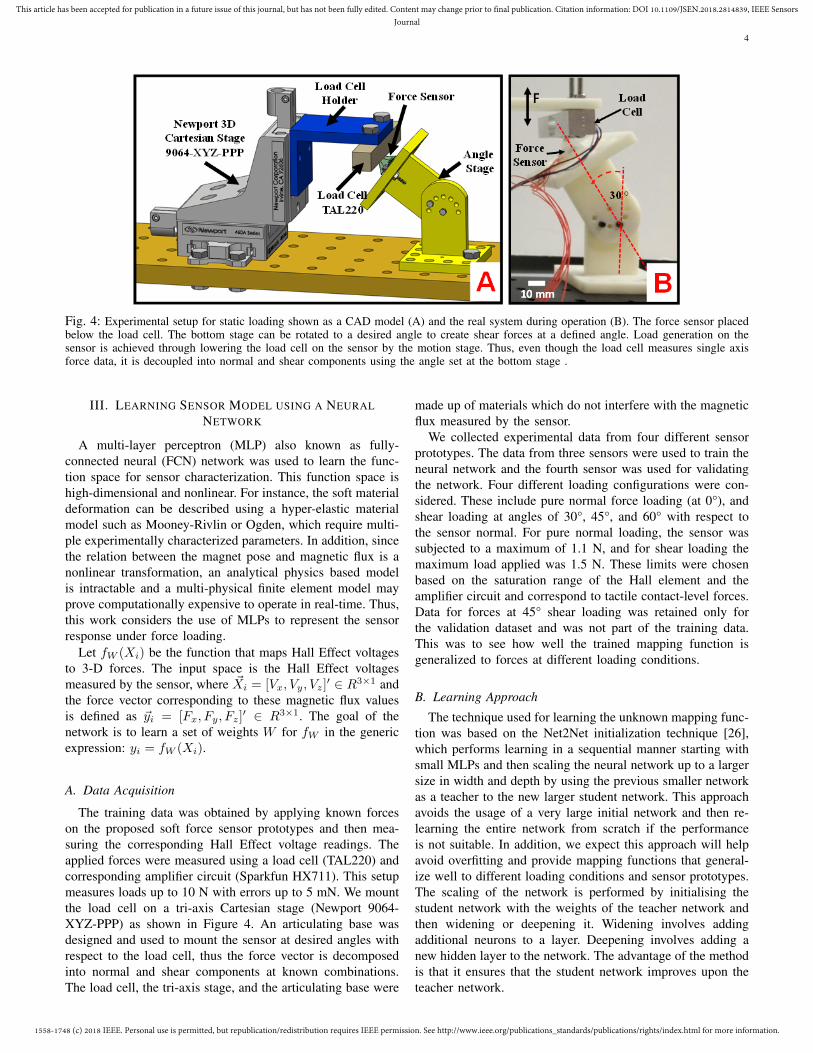
Fig. 4: Experimental setup for static loading shown as a CAD model (A) and the real system during operation (B). The force sensor placedbelow the load cell. The bottom stage can be rotated to a desired angle to create shear forces at a defined angle. Load generation on thesensor is achieved through lowering the load cell on the sensor by the motion stage. Thus, even though the load cell measures single axisforce data, it is decoupled into normal and shear components using the angle set at the bottom stage .
III. LEARNING SENSOR MODEL USING A NEURALNETWORK
A multi-layer perceptron (MLP) also known as fully-connected neural (FCN) network was used to learn the func-tion space for sensor characterization. This function space ishigh-dimensional and nonlinear. For instance, the soft materialdeformation can be described using a hyper-elastic materialmodel such as Mooney-Rivlin or Ogden, which require multi-ple experimentally characterized parameters. In addition, sincethe relation between the magnet pose and magnetic flux is anonlinear transformation, an analytical physics based modelis intractable and a multi-physical finite element model mayprove computationally expensive to operate in real-time. Thus,this work considers the use of MLPs to represent the sensorresponse under force loading.
Let fW (Xi) be the function that maps Hall Effect voltagesto 3-D forces. The input space is the Hall Effect voltagesmeasured by the sensor, where ~Xi = [Vx, Vy, Vz]
′ ∈ R3×1 andthe force vector corresponding to these magnetic flux valuesis defined as ~yi = [Fx, Fy, Fz]
′ ∈ R3×1. The goal of thenetwork is to learn a set of weights W for fW in the genericexpression: yi = fW (Xi).
A. Data Acquisition
The training data was obtained by applying known forceson the proposed soft force sensor prototypes and then mea-suring the corresponding Hall Effect voltage readings. Theapplied forces were measured using a load cell (TAL220) andcorresponding amplifier circuit (Sparkfun HX711). This setupmeasures loads up to 10 N with errors up to 5 mN. We mountthe load cell on a tri-axis Cartesian stage (Newport 9064-XYZ-PPP) as shown in Figure 4. An articulating base wasdesigned and used to mount the sensor at desired angles withrespect to the load cell, thus the force vector is decomposedinto normal and shear components at known combinations.The load cell, the tri-axis stage, and the articulating base were
made up of materials which do not interfere with the magneticflux measured by the sensor.
We collected experimental data from four different sensorprototypes. The data from three sensors were used to train theneural network and the fourth sensor was used for validatingthe network. Four different loading configurations were con-sidered. These include pure normal force loading (at 0°), andshear loading at angles of 30°, 45°, and 60° with respect tothe sensor normal. For pure normal loading, the sensor wassubjected to a maximum of 1.1 N, and for shear loading themaximum load applied was 1.5 N. These limits were chosenbased on the saturation range of the Hall element and theamplifier circuit and correspond to tactile contact-level forces.Data for forces at 45° shear loading was retained only forthe validation dataset and was not part of the training data.This was to see how well the trained mapping function isgeneralized to forces at different loading conditions.
B. Learning Approach
The technique used for learning the unknown mapping func-tion was based on the Net2Net initialization technique [26],which performs learning in a sequential manner starting withsmall MLPs and then scaling the neural network up to a largersize in width and depth by using the previous smaller networkas a teacher to the new larger student network. This approachavoids the usage of a very large initial network and then re-learning the entire network from scratch if the performanceis not suitable. In addition, we expect this approach will helpavoid overfitting and provide mapping functions that general-ize well to different loading conditions and sensor prototypes.The scaling of the network is performed by initialising thestudent network with the weights of the teacher network andthen widening or deepening it. Widening involves addingadditional neurons to a layer. Deepening involves adding anew hidden layer to the network. The advantage of the methodis that it ensures that the student network improves upon theteacher network.
1558-1748 (c) 2018 IEEE. Personal use is permitted, but republication/redistribution requires IEEE permission. See http://www.ieee.org/publications_standards/publications/rights/index.html for more information.
This article has been accepted for publication in a future issue of this journal, but has not been fully edited. Content may change prior to final publication. Citation information: DOI 10.1109/JSEN.2018.2814839, IEEE SensorsJournal
5
TABLE I: MSE Loss in training during widening operation on Pyramidal Sensor
Number of Neurons in FirstHidden Layer 2 4 8 16 18
MSE Loss (N2) 0.0678 0.0325 0.0084 0.0045 0.0041
TABLE II: MSE Loss in training during deepening operation on Pyramidal Sensor
Number of HiddenLayers 1 2 3 4 5
MSE Loss (N2) 0.0041 0.0023 7.07x10⁻⁴ 2.45x10⁻⁴ 1.16x10⁻⁴
TABLE III: Results on the Test Dataset during widening operation on Pyramidal Sensor
Number of Neurons in FirstHidden Layer 2 4 8 16 18
MAE (N) 0.23 0.13 0.092 0.053 0.052Mean Error (N) -0.0016 -0.0026 -0.0037 -0.0048 0.0039
σ(N) 0.2606 0.179 0.0917 0.0664 0.0632
TABLE IV: Results on the Test Dataset during deepening operation on Pyramidal Sensor
Number of Hidden Layers 1 2 3 4 5
MAE (N) 0.052 0.0258 0.015 0.007 0.0056Mean Error (N) 0.0039 0.0028 0.0033 0.00094 0.00025
σ(N) 0.0632 0.0464 0.0262 0.0112 0.0092
C. Metrics for Evaluation
We measure the neural network performance using meanabsolute error (MAE) and standard deviation (σ). Specifically,as each sensor data (Xi) is passed through the network, aprediction (pi) is obtained and the error (ei) is defined as thedifference between this prediction and the actual force (yi).ei = pi− yi where, pi = fW (Xi). MAE and σ are calculatedin standard form:
MAE =
∑Ni=1 eiN
, (1)
σ =
√∑Ni=1 e
2i
N. (2)
D. Training, Testing, and Validation
The total data points were split into training and testingdatasets following the 80-20 convention. Data points obtainedfrom the fourth sensor prototype and for 45o loading wereexcluded from this dataset.
The technique used for training all the Net2Net networksutilized the following hyper parameters. All the models weretrained with Adam as the optimizer and mean-squared-error(MSE) was used as the cost metric to train the network sincethis is a regression problem. The learning rate was scheduledwith initial value being the default 1e−3 (for Adam optimizer).A reduction in learning rate by a factor of 10 was effectedwhenever the loss failed to reduce in 3 consecutive epochs.When the “Learning Rate Scheduler” function is evoked, thebest weights (in terms of least loss) obtained until the functioncall are loaded and training is continued from there. Trainingwas performed for 550 Epochs for each teacher network.
Scaling of the network was done by widening the networkfirst and then deepening it. Widening operation was done to amaximum of 18 neurons and then deepening operations wereperformed up to 5 hidden layers. The final network used forlearning the sensor model contains 5-hidden layers with 18neurons at each layer. We implemented our network modelsusing the software package Keras [28].
E. Training Results
The MSE obtained during training is shown in Table I (forwidening operation) and Table II (for deepening operation).Data from Table I indicate that the training loss convergesand does not improve from 16 neurons to 18 neurons duringthe widening operation. This is the primary reason why thewidening operations were not pursued after 18 neurons. Ashidden layers are added, the training loss is almost halved forevery added layer and is almost 1e−4 thus showing that thenetwork is learning the function space effectively based on thetraining data. After adding the 5th hidden layer we concludedthat further increase in depth will be prone to overfitting.However, this does not provide any insight into the capabilityof the network to generalize for different loading conditionsand sensor prototypes. Section IV-A will demonstrate theresponse of the neural network for loading conditions andsensor prototypes that were not included in the training set.
F. Testing Results
Table III shows the results obtained on the test datasetduring widening operations. As we scale the neurons in thefirst layer we see that the Mean Absolute Error (MAE) andthe Standard Deviation (σ) are reduced. This decrease is veryrapid initially and then slowly converges to steady state at a
1558-1748 (c) 2018 IEEE. Personal use is permitted, but republication/redistribution requires IEEE permission. See http://www.ieee.org/publications_standards/publications/rights/index.html for more information.
This article has been accepted for publication in a future issue of this journal, but has not been fully edited. Content may change prior to final publication. Citation information: DOI 10.1109/JSEN.2018.2814839, IEEE SensorsJournal
6
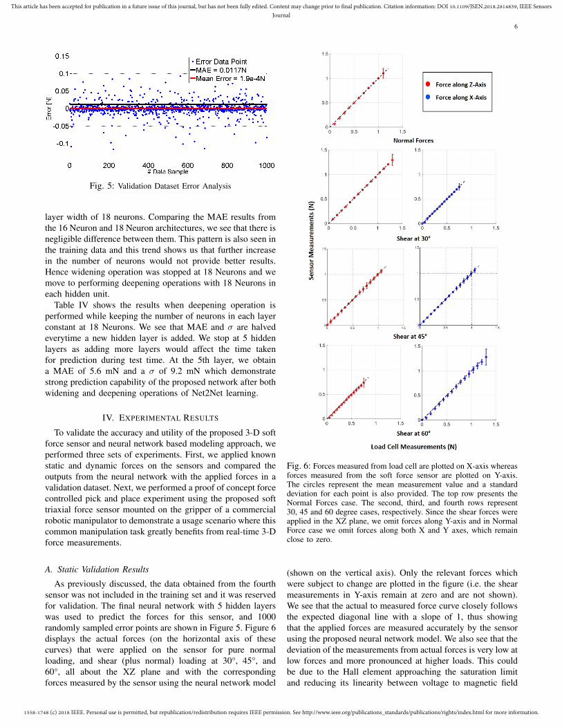
Fig. 5: Validation Dataset Error Analysis
layer width of 18 neurons. Comparing the MAE results fromthe 16 Neuron and 18 Neuron architectures, we see that there isnegligible difference between them. This pattern is also seen inthe training data and this trend shows us that further increasein the number of neurons would not provide better results.Hence widening operation was stopped at 18 Neurons and wemove to performing deepening operations with 18 Neurons ineach hidden unit.
Table IV shows the results when deepening operation isperformed while keeping the number of neurons in each layerconstant at 18 Neurons. We see that MAE and σ are halvedeverytime a new hidden layer is added. We stop at 5 hiddenlayers as adding more layers would affect the time takenfor prediction during test time. At the 5th layer, we obtaina MAE of 5.6 mN and a σ of 9.2 mN which demonstratestrong prediction capability of the proposed network after bothwidening and deepening operations of Net2Net learning.
IV. EXPERIMENTAL RESULTS
To validate the accuracy and utility of the proposed 3-D softforce sensor and neural network based modeling approach, weperformed three sets of experiments. First, we applied knownstatic and dynamic forces on the sensors and compared theoutputs from the neural network with the applied forces in avalidation dataset. Next, we performed a proof of concept forcecontrolled pick and place experiment using the proposed softtriaxial force sensor mounted on the gripper of a commercialrobotic manipulator to demonstrate a usage scenario where thiscommon manipulation task greatly benefits from real-time 3-Dforce measurements.
A. Static Validation Results
As previously discussed, the data obtained from the fourthsensor was not included in the training set and it was reservedfor validation. The final neural network with 5 hidden layerswas used to predict the forces for this sensor, and 1000randomly sampled error points are shown in Figure 5. Figure 6displays the actual forces (on the horizontal axis of thesecurves) that were applied on the sensor for pure normalloading, and shear (plus normal) loading at 30°, 45°, and60°, all about the XZ plane and with the correspondingforces measured by the sensor using the neural network model
Fig. 6: Forces measured from load cell are plotted on X-axis whereasforces measured from the soft force sensor are plotted on Y-axis.The circles represent the mean measurement value and a standarddeviation for each point is also provided. The top row presents theNormal Forces case. The second, third, and fourth rows represent30, 45 and 60 degree cases, respectively. Since the shear forces wereapplied in the XZ plane, we omit forces along Y-axis and in NormalForce case we omit forces along both X and Y axes, which remainclose to zero.
(shown on the vertical axis). Only the relevant forces whichwere subject to change are plotted in the figure (i.e. the shearmeasurements in Y-axis remain at zero and are not shown).We see that the actual to measured force curve closely followsthe expected diagonal line with a slope of 1, thus showingthat the applied forces are measured accurately by the sensorusing the proposed neural network model. We also see that thedeviation of the measurements from actual forces is very low atlow forces and more pronounced at higher loads. This couldbe due to the Hall element approaching the saturation limitand reducing its linearity between voltage to magnetic field
1558-1748 (c) 2018 IEEE. Personal use is permitted, but republication/redistribution requires IEEE permission. See http://www.ieee.org/publications_standards/publications/rights/index.html for more information.
This article has been accepted for publication in a future issue of this journal, but has not been fully edited. Content may change prior to final publication. Citation information: DOI 10.1109/JSEN.2018.2814839, IEEE SensorsJournal
7
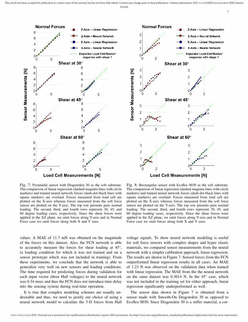
Fig. 7: Pyramidal sensor with Dragonskin 30 as the soft substrate.The comparison of linear regression (dashed magenta lines with circlemarkers) and trained neural network forces (dash-dot black lines withsquare markers) are overlaid. Forces measured from load cell areplotted on the X-axis whereas forces measured from the soft forcesensor are plotted on the Y-axis. The top row presents pure normalloading. The second, third, and fourth rows represent 30, 45, and60 degree loading cases, respectively. Since the shear forces wereapplied in the XZ plane, we omit forces along Y-axis and in NormalForce case we omit forces along both X and Y axes.
values. A MAE of 11.7 mN was obtained on the magnitudeof the forces on this dataset. Also, the FCN network is ableto accurately measure the forces for shear loading at 45°,(a loading condition for which it was not trained and on asensor prototype which was not included in training). Fromthese experiments, we conclude that the network is able togeneralize very well on new sensors and loading conditions.The time required for predicting forces during validation foreach input vector (three Hall voltages) to the neural networkwas 0.34 msec and thus the FCN does not introduce time delayinto the sensing system during real-time operation.
It is true that complex modeling schemes are usually un-desirable and thus, we need to justify our choice of using aneural network model to calculate the 3-D forces from Hall
Fig. 8: Rectangular sensor with Ecoflex 0030 as the soft substrate.The comparison of linear regression (dashed magenta lines with circlemarkers) and trained neural network forces (dash-dot black lines withsquare markers) are overlaid. Forces measured from load cell areplotted on the X-axis whereas forces measured from the soft forcesensor are plotted on the Y-axis. The top row presents pure normalloading. The second, third, and fourth rows represent 30, 45, and60 degree loading cases, respectively. Since the shear forces wereapplied in the XZ plane, we omit forces along Y-axis and in NormalForce case we omit forces along both X and Y axes.
voltage signals. To show neural network modeling is usefulfor soft force sensors with complex shapes and hyper elasticmaterials, we compared sensor measurements from the neuralnetwork with a simpler calibration approach, linear regression.The results are shown in Figure 7. Sensed forces from the FCNoutperformed linear regression results in all cases. An MAEof 1.23 N was observed on the validation data when trainedwith linear regression. The MAE from the the neural networkon the same dataset was 0.3014 N. In the 45° case, whichwas not included in the training set for either approach, linearregression significantly underperformed as well.
The sensor data shown in Figure 7 is obtained from asensor made with Smooth-On Dragonskin 30 as opposed toEcoflex 0030. Since Dragonskin 30 is a stiffer material, a cor-
1558-1748 (c) 2018 IEEE. Personal use is permitted, but republication/redistribution requires IEEE permission. See http://www.ieee.org/publications_standards/publications/rights/index.html for more information.
This article has been accepted for publication in a future issue of this journal, but has not been fully edited. Content may change prior to final publication. Citation information: DOI 10.1109/JSEN.2018.2814839, IEEE SensorsJournal
8
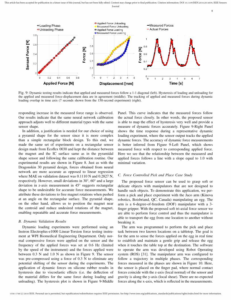
Fig. 9: Dynamic testing results indicate that applied and measured forces follow a 1-1 diagonal (left). Hysteresis of loading and unloading forthe applied and measured force-displacement data are in agreement (middle). The tracking of applied and measured forces during dynamicloading overlap in time axis (7 seconds shown from the 150-second experiment) (right).
responding increase in the measured force range is observed.Our results indicate that the same neural network calibrationapproach adjusts well to different material types with the samesensor shape.
In addition, a justification is needed for our choice of usinga pyramid shape for the sensor since it is more complexthan a simple rectangular block design. To this end, wemade the same set of experiments on a rectangular sensordesign made from Ecoflex 0030 and kept the distance betweenthe magnet and the IC surface same as in the pyramidalshape sensor and following the same calibration routine. Ourexperimental results are shown in Figure 8. Just as with theDragonskin 30 pyramid design, forces obtained from neuralnetwork are more accurate as opposed to linear regressionwhere MAE on validation dataset was 0.1110 N and 0.2827 N,respectively. However, small deviations in 30°, 60° and a largedeviation in z-axis measurement in 45° suggests rectangularshape to be undesirable for accurate force measurements. Weattribute these deviations to free magnet rotations when pushedat an angle on the rectangular surface. The pyramid shape,on the other hand, allows us to position the magnet nearthe centroid and reduce undesired rotations of the magnet,enabling repeatable and accurate force measurements.
B. Dynamic Validation ResultsDynamic loading experiments were performed using an
Instron Electroplus-e1000 Linear-Torsion force testing instru-ment at WPI Biomedical Engineering Department. Only nor-mal compressive forces were applied on the sensor and thefrequency of the applied forces was set at 0.6 Hz (limitedby the speed of the instrument) and the forces applied werebetween 0.3 N and 1.0 N as shown in Figure 9. The sensorwas pre-compressed using a force of 0.3 N to eliminate anypotential shifting of the sensor during the experiments. Theapplication of dynamic forces on silicone rubber results inhysteresis due to viscoelastic effects (i.e. the deflection ofthe material differs for the same force during loading andunloading). The hysteresis plot is shown in Figure 9-Middle
Panel. This curve indicates that the measured forces followthe actual force closely. In other words, the proposed sensoris able to map the effect of hysteresis very well and provide ameasure of dynamic forces accurately. Figure 9-Right Panelshows the time response during a representative dynamicloading experiment, where the sensor output tracks the applieddynamic forces. The accuracy of dynamic force measurementsis better inferred from Figure 9-Left Panel, which showsmeasured force with respect to corresponding applied force.Here we see that the relationship between the measured andapplied forces follows a line with a slope equal to 1.0 withminimal variation.
C. Force Controlled Pick and Place Case Study
The proposed force sensor can be used to grasp soft ordelicate objects with manipulators that are not designed tohandle such objects. To demonstrate this application, we per-form a pick and place experiment with the Jaco arm (Kinovarobotics, Boisbriand, QC, Canada) manipulating an egg. Thearm is a 6-degree-of-freedom (DOF) manipulator with a 3-finger gripper. With the proposed soft tri-axial force sensor weare able to perform force control and thus the manipulator isable to transport the egg from one location to another withoutbreaking it.
The arm was programmed to perform the pick and placetask between two known locations on a tabletop. The goal isfor the arm to sense the forces applied on the egg in real timeto establish and maintain a gentle grip and release the eggwhen it touches the table top at the destination. The softwareto operate the arm was developed using Robot Operatingsystem (ROS) [31]. The manipulator arm was configured tofollow a trajectory in multiple phases. The correspondingforces measured in the phases are shown in Figure 10. Here,the sensor is placed on the finger pad, where normal contactforces coincide with the z-axis (local normal) of the sensor andgravity is along the y-axis (local shear). There are no expectedforces along the x-axis, which is reflected in the measurements.

1558-1748 (c) 2018 IEEE. Personal use is permitted, but republication/redistribution requires IEEE permission. See http://www.ieee.org/publications_standards/publications/rights/index.html for more information.
This article has been accepted for publication in a future issue of this journal, but has not been fully edited. Content may change prior to final publication. Citation information: DOI 10.1109/JSEN.2018.2814839, IEEE SensorsJournal
9
Fig. 10: Significant time intervals from the grasp experiment are shown. At t1 robot is at its initial state and no force is measured on thesensor. Shear force and normal force are detected as fingers get in contact with the object during t2. The interval t3 represents the movementof the object from initial point to the target point. The peak in this interval is due to stabilization of the egg between two fingers. Finallythe object is released by detecting the change in y-axis force in interval t4. A coordinate frame attached to the first snapshot at t1 representsthe measurement axes of the force sensor.
The gap in the gripper when fingers are fully closed wasbigger than the size of the egg. Hence, the gripper fingers werepadded with a silicone rubber layer in order to reduce this gap.The weight of the egg was 50 g. The arm could lift the eggwithout any damage following a simple force-control processas shown as snapshots in Figure 10. The four phases duringthis task are defined as follows:
Gripper Closing Phase: Shown by the period t1 in Fig-ure 10, here the gripper is at the initial pose and the fingersstart closing. All forces remain at 0 N throughout this period,taking about 6 seconds before the fingers make contact withthe egg.
Grasping and Lifting Phase: Shown by the period t2 inFigure 10, here the gripper initiates contact with the egg asseen by the increase in FZ . The fingers continue closing untila predefined threshold is reached to produce a normal graspingforce between contact surfaces to hold on to the object dueto friction, with negligible deformation. The value of the safelimit was determined through prior trials to be 0.15 N to 0.35 N(as measured by the force sensor) for the egg. After graspingthe object, the arm starts lifting up the egg at around 7 seconds.In this phase, the force sensor experiences an increase in theshear force FY due to gravity.
Relocating Phase: Shown by the period t3 in Figure 10,here the arm moves the gripper along with the egg over to adestination location while keeping the gripper position 10 cmabove the desk level. Slight disturbances are seen in this timeperiod which could be attributed to a shaky movement of theJaco arm. The short pulse in this phase at 14 seconds coincideswith a slight shift in the position of the egg between thefingers.
Placing Phase: Shown by the period t4 in Figure 10, thegripper moves down towards the table. As the egg makescontact with the table top, the shear force decreases. Thisdecrease in shear force allows the arm to recognise that theegg has been placed at the destination spot. At this time, theJaco arm opens its grip to release the egg and the arm goesback to the starting position.
The sensing of the shear forces while placing an object helpsthe manipulator to sense that the object has made contact withthe ground surface and allow it to place the object safely andgently at the destination spot without dropping the object orstrongly hitting the ground surface.
V. CONCLUSION AND FUTURE WORK
In this paper we described the design, fabrication, character-ization, and experimental validation of a Hall effect based 3-Dsoft force sensor in a pyramid shaped soft elastomer matrix.We trained a fully-connected neural network for characteri-zation and mapping of measured voltages to 3-D forces. Weshow that the resulting mapping generalizes well for sensorsand loading conditions that are not part of the training dataset.Our experimental results show that the proposed sensor ishighly accurate and it can measure forces in normal and sheardirections within a range of 0 N to 1.1 N and ±1.5 N withan error of 2% and 2.2% of the full scale reading in normaland shear, respectively. The bandwidth of the Melexis sensorIC can work up to 400 Hz. Dynamic loading experimentsindicate that the sensor is able to accurately follow dynamicforces applied at 0.6 Hz despite the hysteresis exhibited bythe material.

1558-1748 (c) 2018 IEEE. Personal use is permitted, but republication/redistribution requires IEEE permission. See http://www.ieee.org/publications_standards/publications/rights/index.html for more information.
This article has been accepted for publication in a future issue of this journal, but has not been fully edited. Content may change prior to final publication. Citation information: DOI 10.1109/JSEN.2018.2814839, IEEE SensorsJournal
10
TABLE V: Comparison of commercial and published force sensors along with the Pyramidal Ecoflex 0030 sensor presented in this paperalong important properties of size, sampling rate, hysteresis, measured force axes, range and sensitivity.
SensorName L×W×H (mm) Sampling
Rate HysteresisDecoupled
Force/TorqueAxes
Range (N) Sensitivity
Tekscan(A101) 15×7×0.2 200 kHz 1 4.5% FS 1 44 No data
providedSingle Tact
Sensor 58×8×0.35 1000 Hz 4% FS 1 10 20 mN
OMD-10-SE-10N 15×11×10 1000 Hz 2% FS 3
Fz = 10Fx = ±2.5Fy = ±2.5
2.5 mN
EmbeddedMicrofluidic
Channels[9]
50×60×7 100 Hz 2 Negligible 3 3Fz = 6Fx = ±1Fy = ±1
10 mN
Tomo et al.[22] 55×55×8 100 Hz No data
provided 4 3Fz = 15Fx = ±6Fy = ±6
No dataprovided
Nie et al.[29]
Diameter:60×11 400 Hz No data
provided 4
Fz = 40Fx = 15Fy = 15Tz = 0.8
10 mN
Liu et al.[30] Diameter: 20×8 5 kHz No data
provided 3Fz = 0.5Fx = 0.5Fy = 0.5
10 mN
This Work:Pyramidal
Ecoflex 003012×12×8 400 Hz Negligible 5 3
Fz = 1.1Fx = ±1.5Fy = ±1.5
5 mN
1The value is based on the response time of the piezoresistive material. The bandwidth may vary for different uses.2Reported sampling rate.3The material will exhibit viscoelastic properties.4The material will exhibit viscoelastic properties.5The pyramid sensor exhibits negligible hysteresis for force measurements. A higher hysteresis of 24% is observedin force-displacement response. This behaviour is due to the viscoelastic nature of the material.
We present a comparison of the pyramidal Ecoflex 0030sensor with commercially available and published force sensordesigns in Table V. Hysteresis in piezoelectric and capacitivecommercially available sensors seems negligible but our find-ings suggest viscoelasticity of soft materials adds significanthysteresis and we expect other works that use similar materialsto exhibit hysteresis effects. In most cases the range of thesensor can be adjusted by picking different soft materials oradjusting the gains of the amplifier attached to the sensor. Thepyramidal Ecoflex 0030 sensor is quite sensitive, measuringforces as small as 5 mN (error range of the load cell usedfor calibration) within a suitable range of 0-1 N for tactileapplications. In Table V, Single Tact Sensor and embeddedmicrofluidic channel based sensor design stand out as highsensitivity sensors within their maximum force range. SingleTact Sensor, however is only capable of measurements in asingle dimension. As for sensitivity the Ecoflex 0030 Pyramidsensor (5 mN) is only outperformed by the commercial OMD-10 sensor (2.5 mN). In terms of package size the Ecoflex 0030Pyramid sensor has a volume of 380 mm3. Sensors having asmaller volume are Tekscan and Single Tact Sensor, whichonly provide normal force measurements. This volume dif-ference is expected since both sensors are fabricated on athin sheet and do not have soft substrates over them. Overall,we conclude that the pyramid sensor shape, magnetic fieldmeasurements, and a soft substrate as the force measurementmedium provides a good combination of size, measured axes,and sensitivity.
A force controlled pick and place experiment was performedon an egg using the force sensor mounted on a Kinova Jacoarm. We show that the sensor provides stable output force datain real-time and we can use both shear and normal force datato successfully perform fragile object manipulation.
Future work will focus on the combination of multiplesensor units in an array. These arrays of force sensors willhelp monitor accurate distributed force measurements in 3-D.More work is planned to further study the effect of the shapeof the sensor and the location of the magnet within this shape.Usage of the sensor in tasks such as walking gait and balanceanalysis and haptic feedback will also be explored.
ACKNOWLEDGEMENTS
The authors would like to thank Joshua R. Gershlak from theBiomedical Engineering Department at WPI for his valuableassistance on the dynamic testing of the sensor.
REFERENCES
[1] R. S. Dahiya, G. Metta, M. Valle, and G. Sandini, “Tactile sensing—fromhumans to humanoids,” IEEE Transactions on Robotics, vol. 26, no. 1,pp. 1–20, 2010.
[2] H. R. Nicholls and M. H. Lee, “A survey of robot tactile sensingtechnology,” The International Journal of Robotics Research, vol. 8,no. 3, pp. 3–30, 1989.
[3] H. Yousef, M. Boukallel, and K. Althoefer, “Tactile sensing for dexter-ous in-hand manipulation in robotics—a review,” Sensors and ActuatorsA: Physical, vol. 167, no. 2, pp. 171 – 187, 2011. Solid-State Sensors,Actuators and Microsystems Workshop.

1558-1748 (c) 2018 IEEE. Personal use is permitted, but republication/redistribution requires IEEE permission. See http://www.ieee.org/publications_standards/publications/rights/index.html for more information.
This article has been accepted for publication in a future issue of this journal, but has not been fully edited. Content may change prior to final publication. Citation information: DOI 10.1109/JSEN.2018.2814839, IEEE SensorsJournal
11
[4] J. J. Clark, “A magnetic field based compliance matching sensor forhigh resolution, high compliance tactile sensing,” in Robotics andAutomation, 1988. Proceedings., 1988 IEEE International Conferenceon, pp. 772–777 vol.2, Apr 1988.
[5] R. B. Katragadda and Y. Xu, “A novel intelligent textile technologybased on silicon flexible skins,” Sensors and Actuators A: Physical,vol. 143, no. 1, pp. 169–174, 2008.
[6] K. Noda, K. Hoshino, K. Matsumoto, and I. Shimoyama, “A shear stresssensor for tactile sensing with the piezoresistive cantilever standing inelastic material,” Sensors and Actuators A: physical, vol. 127, no. 2,pp. 295–301, 2006.
[7] K. Kim, K. R. Lee, W. H. Kim, K.-B. Park, T.-H. Kim, J.-S. Kim, andJ. J. Pak, “Polymer-based flexible tactile sensor up to 32× 32 arraysintegrated with interconnection terminals,” Sensors and Actuators A:Physical, vol. 156, no. 2, pp. 284–291, 2009.
[8] M. Sohgawa, T. Mima, H. Onishi, T. Kanashima, M. Okuyama, K. Ya-mashita, M. Noda, M. Higuchi, and H. Noma, “Tactle array sensorwith inclined chromium/silicon piezoresistive cantilevers embedded inelastomer,” in TRANSDUCERS 2009 - 2009 International Solid-StateSensors, Actuators and Microsystems Conference, pp. 284–287, June2009.
[9] D. M. Vogt, Y. L. Park, and R. J. Wood, “Design and characterization ofa soft multi-axis force sensor using embedded microfluidic channels,”IEEE Sensors Journal, vol. 13, pp. 4056–4064, Oct 2013.
[10] M. Khondoker and D. Sameoto, “Fabrication methods and applicationsof microstructured gallium based liquid metal alloys,” Smart Materialsand Structures, vol. 25, no. 9, p. 093001, 2016.
[11] D. J. Lipomi, M. Vosgueritchian, B. C. Tee, S. L. Hellstrom, J. A. Lee,C. H. Fox, and Z. Bao, “Skin-like pressure and strain sensors based ontransparent elastic films of carbon nanotubes,” Nature nanotechnology,vol. 6, no. 12, pp. 788–792, 2011.
[12] L. Viry, A. Levi, M. Totaro, A. Mondini, V. Mattoli, B. Mazzolai, andL. Beccai, “Flexible three-axial force sensor for soft and highly sensitiveartificial touch,” Advanced materials, vol. 26, no. 17, pp. 2659–2664,2014.
[13] Y. Yang and Y. Chen, “Innovative design of embedded pressure andposition sensors for soft actuators,” IEEE Robotics and AutomationLetters, vol. 3, pp. 656–663, April 2018.
[14] Y. Tenzer, L. P. Jentoft, and R. D. Howe, “The feel of mems barometers:Inexpensive and easily customized tactile array sensors,” IEEE Robotics& Automation Magazine, vol. 21, no. 3, pp. 89–95, 2014.
[15] J. Yi, X. Zhu, L. Shen, B. Sun, and L. Jiang, An Orthogonal CurvatureFiber Bragg Grating Sensor Array for Shape Reconstruction, pp. 25–31.Berlin, Heidelberg: Springer Berlin Heidelberg, 2010.
[16] S. Youssefian, N. Rahbar, and E. Torres-Jara, “Contact behavior of softspherical tactile sensors,” IEEE Sensors Journal, vol. 14, pp. 1435–1442,May 2014.
[17] C. Cho and Y. Ryuh, “Fabrication of flexible tactile force sensorusing conductive ink and silicon elastomer,” Sensors and Actuators A:Physical, vol. 237, pp. 72–80, 2016.
[18] S. Ozel, N. A. Keskin, D. Khea, and C. D. Onal, “A precise embeddedcurvature sensor module for soft-bodied robots,” 2015.
[19] M. Luo, Y. Pan, E. H. Skorina, W. Tao, F. Chen, S. Ozel, andC. D. Onal, “Slithering towards autonomy: a self-contained soft roboticsnake platform with integrated curvature sensing.,” Bioinspiration &biomimetics, vol. 10 5, p. 055001, 2015.
[20] C. Ledermann, S. Wirges, D. Oertel, M. Mende, and H. Woern, “Tactilesensor on a magnetic basis using novel 3d hall sensor-first prototypesand results,” in Intelligent Engineering Systems (INES), 2013 IEEE 17thInternational Conference on, pp. 55–60, IEEE, 2013.
[21] L. Jamone, G. Metta, F. Nori, and G. Sandini, “James: A humanoidrobot acting over an unstructured world,” in Humanoid Robots, 20066th IEEE-RAS International Conference on, pp. 143–150, IEEE, 2006.
[22] T. P. Tomo, S. Somlor, A. Schmitz, L. Jamone, W. Huang, H. Kristanto,and S. Sugano, “Design and characterization of a three-axis hall effect-based soft skin sensor,” Sensors, vol. 16, no. 4, p. 491, 2016.
[23] E. Torres-Jara, I. Vasilescu, and R. Coral, “A soft touch: Complianttactile sensors for sensitive manipulation,” 2006.
[24] T. P. Tomo, W. K. Wong, A. Schmitz, H. Kristanto, S. Somlor, J. Hwang,and S. Sugano, “Snr modeling and material dependency test of a low-cost and simple to fabricate 3d force sensor for soft robotics,” inSystem Integration (SII), 2016 IEEE/SICE International Symposium on,pp. 428–433, IEEE, 2016.
[25] J. Gafford, F. Doshi-Velez, R. Wood, and C. Walsh, “Machine learningapproaches to environmental disturbance rejection in multi-axis opto-electronic force sensors,” Sensors and Actuators A: Physical, vol. 248,pp. 78–87, 2016.
[26] T. Chen, I. Goodfellow, and J. Shlens, “Net2net: Accelerating learningvia knowledge transfer,” arXiv preprint arXiv:1511.05641, 2015.
[27] C. Li, P. M. Wu, S. Lee, A. Gorton, M. J. Schulz, and C. H. Ahn,“Flexible dome and bump shape piezoelectric tactile sensors using pvdf-trfe copolymer,” Journal of Microelectromechanical Systems, vol. 17,pp. 334–341, April 2008.
[28] F. Chollet, “Keras.” https://github.com/fchollet/keras, 2015.[29] Q. Nie and F. C. Sup, “A soft four degree-of-freedom load cell based
on the hall effect,” IEEE Sensors Journal, vol. 17, pp. 7355–7363, Nov2017.
[30] Y. Liu, H. Han, T. Liu, J. Yi, Q. Li, and Y. Inoue, “A novel tactilesensor with electromagnetic induction and its application on stick-slipinteraction detection,” Sensors, vol. 16, no. 4, 2016.
[31] M. Quigley, K. Conley, B. Gerkey, J. Faust, T. Foote, J. Leibs,R. Wheeler, and A. Y. Ng, “Ros: an open-source robot operating system,”in ICRA workshop on open source software, vol. 3, p. 5, Kobe, 2009.