Embed Size (px)
Citation preview
Composites Part B 225 (2021) 109224
A1
Contents lists available at ScienceDirect
Composites Part B
journal homepage: www.elsevier.com/locate/composites
Design, modeling, optimization, manufacturing and testing of variable-anglefilament-wound cylindersJosé Humberto S. Almeida Jr. a,b,∗, Luc St-Pierre a, Zhihua Wang c,d, Marcelo L. Ribeiro e,Volnei Tita e, Sandro C. Amico f, Saullo G.P. Castro c,∗
a Department of Mechanical Engineering, Aalto University, Espoo, Finlandb Advanced Composites Research Group, School of Mechanical and Aerospace Engineering, Queen’s University Belfast, Belfast, UKc Faculty of Aerospace Engineering, Delft University of Technology, Delft, The Netherlandsd School of Mechanical and Electrical Engineering, University of Electronic Science and Technology of China, Chengdu, Chinae Department of Aeronautical Engineering, São Carlos School of Engineering, University of São Paulo, São Carlos, SP, Brazilf PPPGE3M/PROMEC, Federal University of Rio Grande do Sul, Porto Alegre, RS, Brazil
A R T I C L E I N F O
Keywords:OptimizationVariable-angleVariable stiffnessModelingBucklingFilament winding
A B S T R A C T
This work demonstrates the potential of manufacturing variable-angle composite cylinders via filament winding(FW), called VAFW. The proposed design strategy allows different filament angles along the axial direction bydividing the cylinder into regions of constant angle called frames. Designs using two, four, or eight frames areherein investigated. A genetic algorithm is applied to optimize each design for maximum axial buckling load. Adesign with minimum manufacturable filament angle is included in the study. All structures are manufacturedand tested under axial compression, with displacements and strains measured by digital image correlation(DIC). The thickness and mid-surface imperfections of the different designs are measured through DIC and usedto explain the observed buckling mechanisms. These imperfections are incorporated into a nonlinear numericalmodel along with a progressive damage analysis. Additionally, a scaling factor is applied on the measuredimperfections to enable an imperfection sensitivity study on the proposed designs. The VAFW design showsbuckling strength, stiffness, and absorbed energy substantially higher than the constant-angle configuration,attributed to tailored thickness buildup and optimized tow steered angles at particular regions of the cylinder.The experimental and numerical results indicate that VAFW designs can be tailored to postpone buckling sothat the material strength can be better exploited.
1. Introduction
Filament winding (FW) is one of the most suitable manufacturingprocesses for fiber-reinforced solids of revolution [1], such as compositeoverwrapped pressure vessels [2,3], tubes [4], pipelines [5,6], driveshafts [7], among others. The FW process is well-suited for automa-tion, being fast, cost-effective and compatible with high fiber volumerequirements of lightweight and high-performance structures [8]. Thereare numerous reports in the literature dealing with constant-angle(i.e. constant-stiffness) filament-wound structures, that is, when eachlayer has a nominal filament angle and a regular thickness distribu-tion [9]. However, recently, Wang et al. [10] designed and optimizedfor the first time variable-angle filament-wound (VAFW) compositecylinders considering the uncertainties and characteristics of the FWprocess, and later focused on minimum-mass optimizations constrainedby target design loads [11]. Based on that, the present investigation
∗ Corresponding authors.E-mail addresses: [email protected] (J.H.S. Almeida Jr.), [email protected] (S.G.P. Castro).
focuses on the innovative manufacturing and testing of VAFW cylin-ders, and the possibility of validating numerical models to investigateobserved failure mechanisms.
It is already well established that variable-angle configurations (alsoknown as variable-axial [12], variable angle tow – VAT [13], tow-steered [14] and variable-stiffness – VS [15]), in which stiffness canbe tailored to follow load paths, are more effective than conven-tional laminates (e.g., quasi-isotropic laminates) in terms of weightsavings, given the higher design freedom due to locally tailored fiberangles [16,17]. Since the establishment of VAT composites by Gürdaland Olmedo [15], this concept is under continuous development bythe aerospace sector. For instance, Hao et al. [18] generated the fiberpath through linear variation, cubic polynomial, contour lines of cubicfunction and flow field functions and optimized VS panels for maximumbuckling load. The flow field method requires only a few variables to
vailable online 20 August 2021359-8368/© 2021 The Author(s). Published by Elsevier Ltd. This is an open access a
https://doi.org/10.1016/j.compositesb.2021.109224Received 10 March 2021; Received in revised form 6 July 2021; Accepted 10 Augu
rticle under the CC BY license (http://creativecommons.org/licenses/by/4.0/).
st 2021

Composites Part B 225 (2021) 109224J.H.S. Almeida Jr. et al.
tmw1
r
r
mu(Prgplvhicc
eaonfor
achieve complicated fiber paths, leading to designs that can be directlymanufactured when curvature constraints are used in the optimization.Hao et al. [19–21] also developed integrated optimization frameworksbased on isogeometric analysis for VS panels, providing an efficientnumerical framework based on the isoparametric concept, which issimilar to the finite element (FE) analysis and meshless method. Theyutilized non-uniform rational B-spline (NURBS) basis functions to dis-cretize the geometric model. In brief, they developed efficient andreliable optimization frameworks at reasonable computational cost,whilst robust enough to generate complex fiber paths, which is hardlypossible to reach in a single optimization step using gradient-basedmethods.
VAT cylinders were first studied by Tatting [22], who analyzed com-putationally VAT shells in bending with both axial and circumferentialangle variations and found significant improvement in terms of criticalbuckling load. Nevertheless, the first attempt to manufacture a VATcylinder was performed by Blom et al. [23], exploiting the potentialof the automated fiber placement (AFP) process. They also carried outmodal tests on non-optimized VAT shells and constant-angle ones withquasi-isotropic (QI) stacking sequence [24]. Blom et al. [25] optimizedthese shells for buckling load under pure bending by steering fibersalong the circumferential direction. These shells were further optimizedby the same group [26] with fibers along the axial direction, wherethe best results were found for cylinders with circumferential stiffnessvariation, having a bending-buckling capacity 18.5% higher than aQI cylinder of the same weight. At the same time, Wu et al. [27]designed and manufactured VAT shells using graphite/epoxy slit tapematerial via AFP. Some shells were manufactured with tow overlapsusing a cut-and-restart procedure, which penalized the manufacturingefficiency. They reported kinks, waves, and bumps in the tows, butthese defects could be avoided by slowing down the fiber placementand increasing the compaction force. Later on, Wu et al. [28] tested[±45∕±𝜃]2𝑆 VAT shells under axial compression, where 𝜃 is the steeringangle that varies along the cylinder circumference. The VAT cylinderwith overlaps yielded pre-buckling stiffness and buckling load 62%and 126% higher than the one without overlaps, respectively. Theyalso concluded that VAT shells were less sensitive to geometric im-perfections than QI ones. These cylinders were also assessed by Whiteet al. [29], regarding their post-buckling performance. Although thenumerical predictions by Wu et al. [27–29] were in good agreementwith experimental observations, buckling tests and analyses showedpoor correlation, most likely attributed to the presence of geometricimperfections that acted as failure initiator. Later, Wu et al. [30]performed a numerical investigation taking into account geometricimperfections of both shells in their numerical models and concludedthat circumferential variations in axial stiffness are responsible forsuppressing sensitivity to geometric imperfections, possibly aiding inthe agreement between tests and simulation results in their previousworks. Rouhi et al. [31] designed and manufactured carbon/epoxy[±𝜃∕0∕90]𝑆 VAT cylinders (diameter: 381 mm and length: 762 mm)hrough AFP, optimized for maximum buckling load in bending using aetamodel-based optimization approach. The baseline for comparisonas a QI shell where ±45◦ replaced 𝜃. The bending-buckling load was8.5% higher for the optimized shell compared to the QI one.
The literature review on manufacturing of VA composite cylindersevealed:
• there are no reports on VA cylinders produced via FW, whosemain benefits over AFP are related to its higher productivity;
• no studies on the optimization of VAT shells considering fiberangle variations along the axial direction;
• no reports on the variable thickness pattern of VAFW cylinders;• no investigations dealing with experimental axial compression
of filament-wound cylinders, including digital image correlationmeasurements for a clearer assessment of the buckling mecha-
2
nism;
• neither measurement nor incorporation of experimentally-measured geometric imperfections into nonlinear FE models offilament-wound structures.
In this context, the present work covers, for the first time, design,modeling, optimization, manufacturing, and testing of VAFW com-posite cylinders. First, the cylinders are optimized using a geneticalgorithm for maximizing their axial compression buckling load byaxially varying the angle; Second, the cylinders are manufactured viaFW; Prior to the tests, the geometric topography is measured [32] usingdigital image correlation (DIC); The shells are tested in axial com-pression assisted by DIC; Finally, experimentally measured geometricimperfection data is used to build numerical models incorporating theobserved thickness variation of the as-manufactured specimens [33],along with a progressive damage model that enables a full post-failureanalysis used to predict the mechanical response and failure mechanismof the VAFW cylinders.
2. Design and optimization
2.1. Design
Throughout this article, the novel cylinders herein studied are calledVAFW. Four designs are investigated:
MA: non-optimized constant-angle cylinder with a winding angle of±50◦, which is the minimum angle (MA) for the utilized mandrel toavoid fiber slippage - Fig. 1(a);
CA: constant-angle with two frames, design variable 𝜃𝐶𝐴1 - Fig. 1(b);
VAFW4: variable-angle with four frames, design variables𝜃𝑉 𝐴41 , 𝜃𝑉 𝐴4
2 - Fig. 1(c);VAFW8: variable-angle with eight frames, design variables
𝜃𝑉 𝐴81 , 𝜃𝑉 𝐴8
2 , 𝜃𝑉 𝐴83 , 𝜃𝑉 𝐴8
4 - Fig. 1(d);
2.2. Linear finite element modeling
In this Section, the linear finite element modeling (FEM) is pre-sented in detail. The composite cylinders under investigation here are300mm long with a diameter of 136mm, whose layup consists of anangle-ply layer, ±𝜃, nominal thickness of 0.8 mm, i.e. a radius-to-thickness ratio of 85. The experimentally-measured material propertiesused in all simulations are listed in Table 1, which are representativeof towpregs with Toray T700-12K-50C carbon fibers and UF3369 epoxyesin.
The FE models are generated using Abaqus CAE FE package and theodels are parameterized via Python scripts. The cylinders are meshedsing four-node reduced integration general purpose shell elementsS4R), with three integration points through-thickness for each layer.revious simulations with full integration were carried out and as theesults were the same, elements with reduced integration were choseniven their lower computational costs, crucial for an optimizationrocedure in which several simulations need to be run. In addition,ow-order elements with full integration are more susceptible to eitherolumetric (typical of incompressible materials with Poisson’s ratioigher than 0.5), membrane or shear locking (usually when a structures under bending), in which the mesh has to be very fine to over-ome these locking effects, making both simulation and optimizationomputationally inefficient.
In order to apply the loads and boundary conditions (BCs), a refer-nce point is set at the center of each free edge of the cylindrical shellsnd connected using multi-point constraint (MPC), see Fig. 2. This typef constraint was selected to equally distribute the displacement on allodes connected to the free edges. All degrees-of-freedom are restrictedor nodes at the bottom edge (𝑧 = 0), the top nodes (𝑧 = 𝐿) arenly allowed to move axially, and all other degrees-of-freedom areestricted. A buckling load (𝐹𝑍 ) is applied at the top reference point
(𝑅𝑃 ). The converged mesh, depicted in Fig. 2, has 152 elements along
1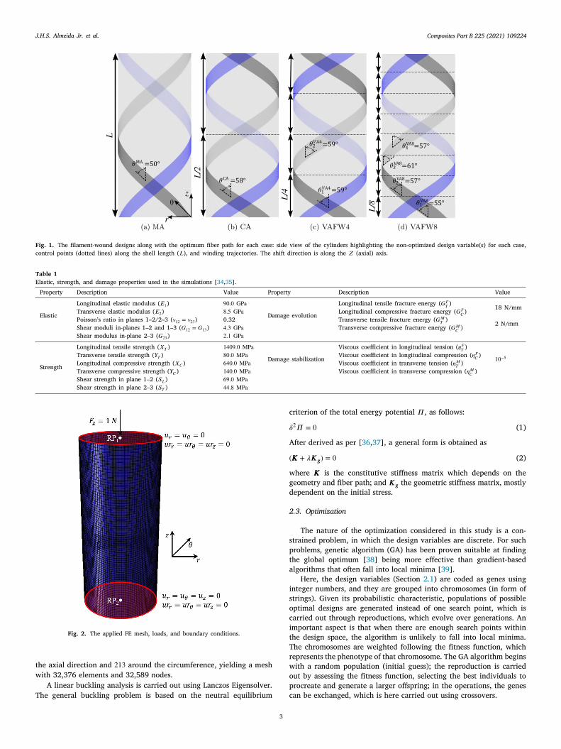
Composites Part B 225 (2021) 109224J.H.S. Almeida Jr. et al.
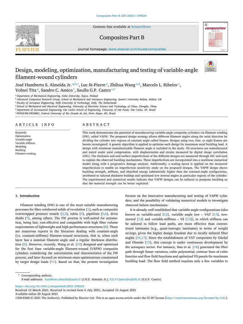
Fig. 1. The filament-wound designs along with the optimum fiber path for each case: side view of the cylinders highlighting the non-optimized design variable(s) for each case,control points (dotted lines) along the shell length (𝐿), and winding trajectories. The shift direction is along the 𝑍 (axial) axis.
Table 1Elastic, strength, and damage properties used in the simulations [34,35].
Property Description Value Property Description Value
Elastic
Longitudinal elastic modulus (𝐸1) 90.0 GPa
Damage evolution
Longitudinal tensile fracture energy (𝐺𝐹𝑇 ) 18 N/mmTransverse elastic modulus (𝐸2) 8.5 GPa Longitudinal compressive fracture energy (𝐺𝐹
𝐶 )Poisson’s ratio in planes 1–2/2–3 (𝜈12 = 𝜈23) 0.32 Transverse tensile fracture energy (𝐺𝑀
𝑇 ) 2 N/mmShear moduli in-planes 1–2 and 1–3 (𝐺12 = 𝐺13) 4.3 GPa Transverse compressive fracture energy (𝐺𝑀𝐶 )
Shear modulus in-plane 2–3 (𝐺23) 2.1 GPa
Strength
Longitudinal tensile strength (𝑋𝑇 ) 1409.0 MPa
Damage stabilization
Viscous coefficient in longitudinal tension (𝜂𝐹𝑇 )
10−5Transverse tensile strength (𝑌𝑇 ) 80.0 MPa Viscous coefficient in longitudinal compression (𝜂𝐹𝐶 )Longitudinal compressive strength (𝑋𝐶 ) 640.0 MPa Viscous coefficient in transverse tension (𝜂𝑀𝑇 )Transverse compressive strength (𝑌𝐶 ) 140.0 MPa Viscous coefficient in transverse compression (𝜂𝑀𝐶 )Shear strength in plane 1–2 (𝑆𝐿) 69.0 MPaShear strength in plane 2–3 (𝑆𝑇 ) 44.8 MPa
Fig. 2. The applied FE mesh, loads, and boundary conditions.
the axial direction and 213 around the circumference, yielding a meshwith 32,376 elements and 32,589 nodes.
A linear buckling analysis is carried out using Lanczos Eigensolver.The general buckling problem is based on the neutral equilibrium
3
criterion of the total energy potential 𝛱 , as follows:
𝛿2𝛱 = 0 (1)
After derived as per [36,37], a general form is obtained as
(𝐾𝐾𝐾 + 𝜆𝑲𝒈) = 0 (2)
where 𝐾𝐾𝐾 is the constitutive stiffness matrix which depends on thegeometry and fiber path; and 𝑲𝒈 the geometric stiffness matrix, mostlydependent on the initial stress.
2.3. Optimization
The nature of the optimization considered in this study is a con-strained problem, in which the design variables are discrete. For suchproblems, genetic algorithm (GA) has been proven suitable at findingthe global optimum [38] being more effective than gradient-basedalgorithms that often fall into local minima [39].
Here, the design variables (Section 2.1) are coded as genes usinginteger numbers, and they are grouped into chromosomes (in form ofstrings). Given its probabilistic characteristic, populations of possibleoptimal designs are generated instead of one search point, which iscarried out through reproductions, which evolve over generations. Animportant aspect is that when there are enough search points withinthe design space, the algorithm is unlikely to fall into local minima.The chromosomes are weighted following the fitness function, whichrepresents the phenotype of that chromosome. The GA algorithm beginswith a random population (initial guess); the reproduction is carriedout by assessing the fitness function, selecting the best individuals toprocreate and generate a larger offspring; in the operations, the genescan be exchanged, which is here carried out using crossovers.
Composites Part B 225 (2021) 109224J.H.S. Almeida Jr. et al.
di
3
3
aTapMtccodfi
tesomtVtd‘to
Aar
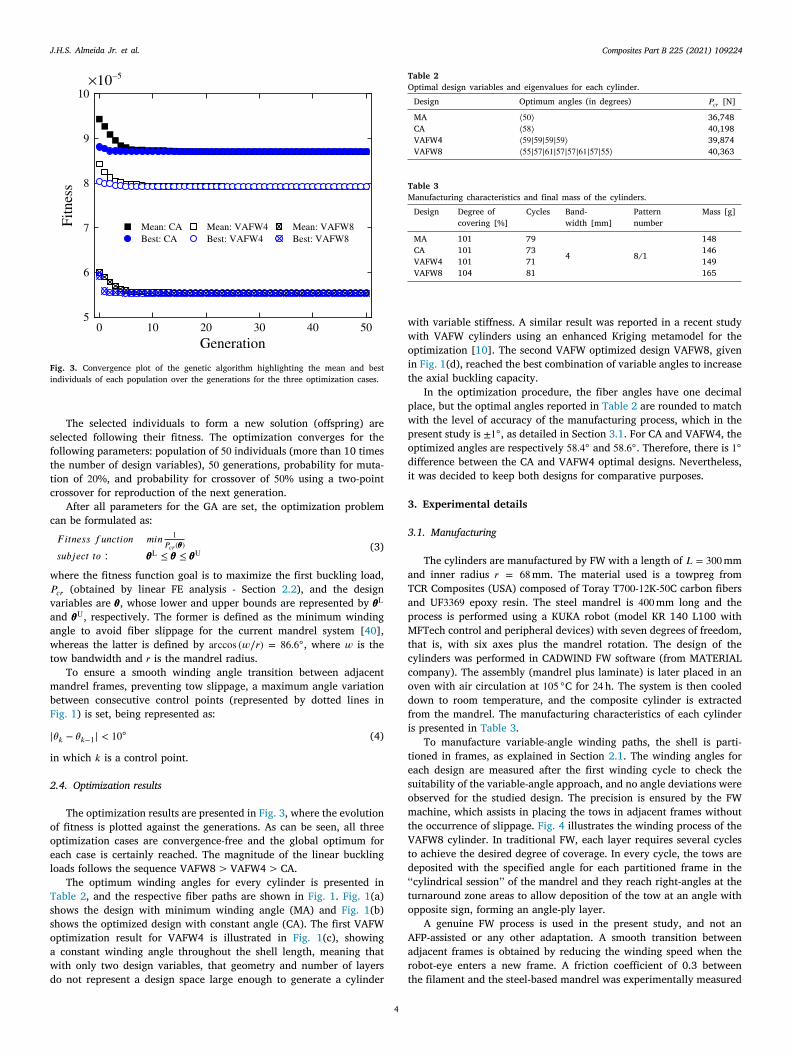
Fig. 3. Convergence plot of the genetic algorithm highlighting the mean and bestindividuals of each population over the generations for the three optimization cases.
The selected individuals to form a new solution (offspring) areselected following their fitness. The optimization converges for thefollowing parameters: population of 50 individuals (more than 10 timesthe number of design variables), 50 generations, probability for muta-tion of 20%, and probability for crossover of 50% using a two-pointcrossover for reproduction of the next generation.
After all parameters for the GA are set, the optimization problemcan be formulated as:𝐹 𝑖𝑡𝑛𝑒𝑠𝑠 𝑓𝑢𝑛𝑐𝑡𝑖𝑜𝑛 𝑚𝑖𝑛 1
𝑃𝑐𝑟(𝜃𝜃𝜃)𝑠𝑢𝑏𝑗𝑒𝑐𝑡 𝑡𝑜 ∶ 𝜃𝜃𝜃L ≤ 𝜃𝜃𝜃 ≤ 𝜃𝜃𝜃U
(3)
where the fitness function goal is to maximize the first buckling load,𝑃𝑐𝑟 (obtained by linear FE analysis - Section 2.2), and the designvariables are 𝜃𝜃𝜃, whose lower and upper bounds are represented by 𝜃𝜃𝜃L
and 𝜃𝜃𝜃U, respectively. The former is defined as the minimum windingangle to avoid fiber slippage for the current mandrel system [40],whereas the latter is defined by arccos (𝑤∕𝑟) = 86.6◦, where 𝑤 is thetow bandwidth and 𝑟 is the mandrel radius.
To ensure a smooth winding angle transition between adjacentmandrel frames, preventing tow slippage, a maximum angle variationbetween consecutive control points (represented by dotted lines inFig. 1) is set, being represented as:
|𝜃𝑘 − 𝜃𝑘−1| < 10◦ (4)
in which 𝑘 is a control point.
2.4. Optimization results
The optimization results are presented in Fig. 3, where the evolutionof fitness is plotted against the generations. As can be seen, all threeoptimization cases are convergence-free and the global optimum foreach case is certainly reached. The magnitude of the linear bucklingloads follows the sequence VAFW8 > VAFW4 > CA.
The optimum winding angles for every cylinder is presented inTable 2, and the respective fiber paths are shown in Fig. 1. Fig. 1(a)shows the design with minimum winding angle (MA) and Fig. 1(b)shows the optimized design with constant angle (CA). The first VAFWoptimization result for VAFW4 is illustrated in Fig. 1(c), showinga constant winding angle throughout the shell length, meaning thatwith only two design variables, that geometry and number of layers
4
do not represent a design space large enough to generate a cylinder t
Table 2Optimal design variables and eigenvalues for each cylinder.
Design Optimum angles (in degrees) 𝑃𝑐𝑟 [N]
MA ⟨50⟩ 36,748CA ⟨58⟩ 40,198VAFW4 ⟨59|59|59|59⟩ 39,874VAFW8 ⟨55|57|61|57|57|61|57|55⟩ 40,363
Table 3Manufacturing characteristics and final mass of the cylinders.
Design Degree ofcovering [%]
Cycles Band-width [mm]
Patternnumber
Mass [g]
MA 101 79
4 8/1
148CA 101 73 146VAFW4 101 71 149VAFW8 104 81 165
with variable stiffness. A similar result was reported in a recent studywith VAFW cylinders using an enhanced Kriging metamodel for theoptimization [10]. The second VAFW optimized design VAFW8, givenin Fig. 1(d), reached the best combination of variable angles to increasethe axial buckling capacity.
In the optimization procedure, the fiber angles have one decimalplace, but the optimal angles reported in Table 2 are rounded to matchwith the level of accuracy of the manufacturing process, which in thepresent study is ±1◦, as detailed in Section 3.1. For CA and VAFW4, theoptimized angles are respectively 58.4◦ and 58.6◦. Therefore, there is 1◦ifference between the CA and VAFW4 optimal designs. Nevertheless,t was decided to keep both designs for comparative purposes.
. Experimental details
.1. Manufacturing
The cylinders are manufactured by FW with a length of 𝐿 = 300mmnd inner radius 𝑟 = 68mm. The material used is a towpreg fromCR Composites (USA) composed of Toray T700-12K-50C carbon fibersnd UF3369 epoxy resin. The steel mandrel is 400mm long and therocess is performed using a KUKA robot (model KR 140 L100 withFTech control and peripheral devices) with seven degrees of freedom,
hat is, with six axes plus the mandrel rotation. The design of theylinders was performed in CADWIND FW software (from MATERIALompany). The assembly (mandrel plus laminate) is later placed in anven with air circulation at 105 ◦C for 24h. The system is then cooledown to room temperature, and the composite cylinder is extractedrom the mandrel. The manufacturing characteristics of each cylinders presented in Table 3.
To manufacture variable-angle winding paths, the shell is parti-ioned in frames, as explained in Section 2.1. The winding angles forach design are measured after the first winding cycle to check theuitability of the variable-angle approach, and no angle deviations werebserved for the studied design. The precision is ensured by the FWachine, which assists in placing the tows in adjacent frames without
he occurrence of slippage. Fig. 4 illustrates the winding process of theAFW8 cylinder. In traditional FW, each layer requires several cycles
o achieve the desired degree of coverage. In every cycle, the tows areeposited with the specified angle for each partitioned frame in the
‘cylindrical session’’ of the mandrel and they reach right-angles at theurnaround zone areas to allow deposition of the tow at an angle withpposite sign, forming an angle-ply layer.
A genuine FW process is used in the present study, and not anFP-assisted or any other adaptation. A smooth transition betweendjacent frames is obtained by reducing the winding speed when theobot-eye enters a new frame. A friction coefficient of 0.3 between
he filament and the steel-based mandrel was experimentally measured
Composites Part B 225 (2021) 109224J.H.S. Almeida Jr. et al.
Fig. 4. The used Kuka robot and photograph of a VAFW8 cylinder being manufactured.
Fig. 5. Description of the casting procedure.
using the procedure detailed in Dalibor et al. [40]. A similar value forthis material was also reported by Zu et al. [41]. Moreover, the robothas an angle tolerance of ±0.15◦ in the deposition process, which is thetolerance control of the 7th axis.
The wrist axes, namely the rotating axes, are essential to minimizefilament in-plane bending during deposition and aid, to some extent, in-plane shear on the filament. Therefore, the variable-angle is achievedthrough a combination of in-plane bending and shear, as described inWang et al. [10]. Minimization of filament in-plane bending is achievedmainly by controlling and synchronizing the A4 wrist axis (see Fig. 4)to keep the filament as close as possible to the mandrel, which alsoprevents twisting. Here, the same winding pattern of 3/1 is used forall cylinders, minimizing the formation of gaps and overlaps [42].Nevertheless, as shown in Table 3, it is not always possible to obtain acoverage of 100%, and a coverage as close as possible to 100% is chosento prevent gaps, unavoidably leading to a thickness buildup in someareas. It is worth mentioning that neither fiber waviness nor wrinklesare observed in any of the manufactured cylinders.
3.2. Specimen preparation
Three cylinders of each design are manufactured, 12 in total. Inorder to enhance the load distribution around the specimen edge andprevent premature failure, a resin potting procedure is carried out usinga metal-filled black-colored epoxy resin CW 2418-1 and hardener REN
5
HY 5160 (100:15 ratio), both from Huntsman Corporation. The low-cost procedure consists of five steps, as per Fig. 5: (i) mold production;(ii) release agent application; (iii) casting one edge of the cylinderand curing for 16h at room temperature; (iv) casting the other edgeensuring parallelism and curing for 16 h; and (v) removal of cylinderfrom the mold.
The molds are made of medium-density fiberboard (MDF), whichare machined using a saw cup. After that, they are machined withcross-section dimensions of 15 × 15 mm, painted, and a release tapeis applied onto the inner cavity. The upper mold is machined with fourrectangular bars to aid alignment. Also, when the second potting iscuring, a weight is placed on top of the mold (see Fig. 5) to ensurethat the entire cylinder edge is in contact with the inner cavity of themold. After curing, the whole mold apparatus can be easily removedand the cylinder is ready to be tested. Representative specimens aredepicted in Fig. 6.
3.3. Testing
The cylinders herein investigated are subjected to axial compres-sion. A Zwick Roell universal testing machine model LF7M19 witha load cell of 250 kN is used with compressive platens of 175mm indiameter. The displacement-controlled tests are conducted at a rate of1mm/min.
The cylinders are painted to perform DIC measurements. The DICis used to monitor both global displacements and strain field on about

Composites Part B 225 (2021) 109224J.H.S. Almeida Jr. et al.
Fig. 6. The prepared cylinders prior to testing.
Fig. 7. Axial compression test apparatus with the DIC system used for displacementand strain measurements during the tests.
60◦ of the cylinder’s surface. During the deformation, the DIC tracksthe gray value pattern in small neighborhoods called subsets. Thecalibration of the DIC system is performed before testing each cylinder,with the specimen compressed at a preload of 200N, which is sufficientto remove slack from all force–displacement curves. This strategy alsoplays a key role in stabilizing and aligning the sample between thecompressive platens. Fig. 7 schematically depicts the experimentalsetup. In this study, two 9 megapixel cameras with 50mm lenses areused.
3.4. Variable thickness patterns
Before the compression tests, the surface topography of all cylindersis measured using the same DIC system. Castro et al. [32] describein detail the algorithm to do the thickness imperfection measurementusing data from only one pair of cameras. In brief, the procedureconsists in collecting DIC raw data from 6 circumferential positionsalong the cylindrical shell and transforming them to a common ref-erence frame. Next, the raw data is rotated to the position of thecorresponding section, with a fine adjustment based on mean-squaredvalue error. Once all sections are reconstructed, the surface topographycan be precisely determined by knowing that the outer surface ofthe mandrel is smooth. These measured imperfections are afterwardsimprinted in nonlinear FE models (see Section 4) to reproduce theimperfect geometries.
The stitched imperfection patterns adopted for each VAFW cylinderare shown in Fig. 8. The raw DIC data [43] and reconstructed three-dimensional imperfection data [44] are available for public access.
6
3.5. Experimental results
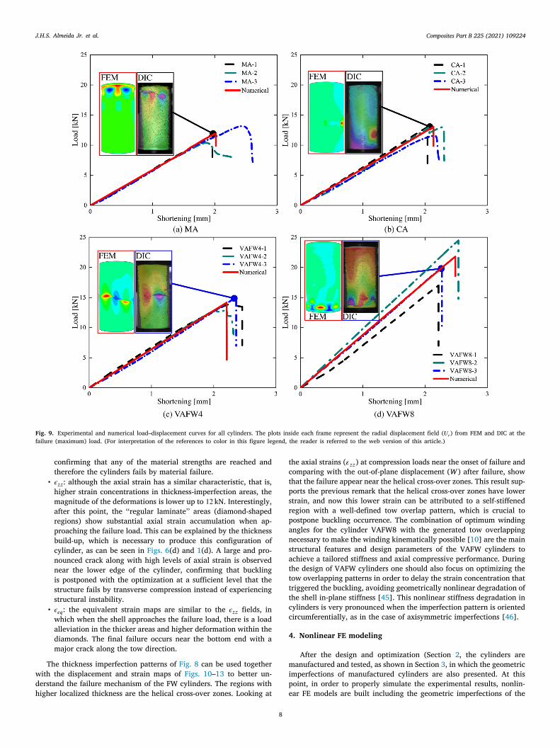
After obtaining substantial improvement in terms of buckling loadfrom the optimization process, both non-optimized and optimized cylin-ders are manufactured and tested. The experimental load-shortening curves are shown in Fig. 9 (Section 5), where three samplesare tested for each family of cylinder. Generally speaking, there is avery good repeatability, as expected from an automated process suchas filament winding. The designed cylinders VAFW8 have clearly moredeviation on stiffness and failure load. For the non-optimized baselineMA cylinder (Fig. 9(a)), all three specimens present negligible variationin terms of stiffness. Specimen MA–3 has a greater failure load, butits axial stiffness is similar to the other two MA samples. As givenin Table 5, the MA design has an axial stiffness of 5.8 ± 0.1 kN∕mm,and a failure load of 11.8 ± 1.4 kN. Fig. 9(b) presents the test resultsfor the cylinder CA, showing an average stiffness of 5.9 ± 0.4 kN∕mmand failure load of 12.5±0.8 kN. Fig. 9(c) shows the load–displacementcurves for the VAFW4 cylinder, with stiffness of 6.4 ± 0.4 kN∕mm andfailure load of 13.5 ± 1.1 kN. The optimized VAFW8 cylinders (9(d))have the highest stiffness (8.5 ± 1.4 kN∕mm) and failure load (20.5 ±3.8 kN) among all designs. The results for the VAFW8 cylinder showthe great potential of the proposed VAFW designs to improve themechanical performance of cylindrical shells. This family of cylindersshows, nonetheless, higher variations compared to the other cylinderdesigns, which can be attributed to possible small angle variations atthe control points areas. In addition, the large number of frames alongthe axial direction of the cylinder can yield several transitions betweenframes, whose zones might show a small tow angle deviation.
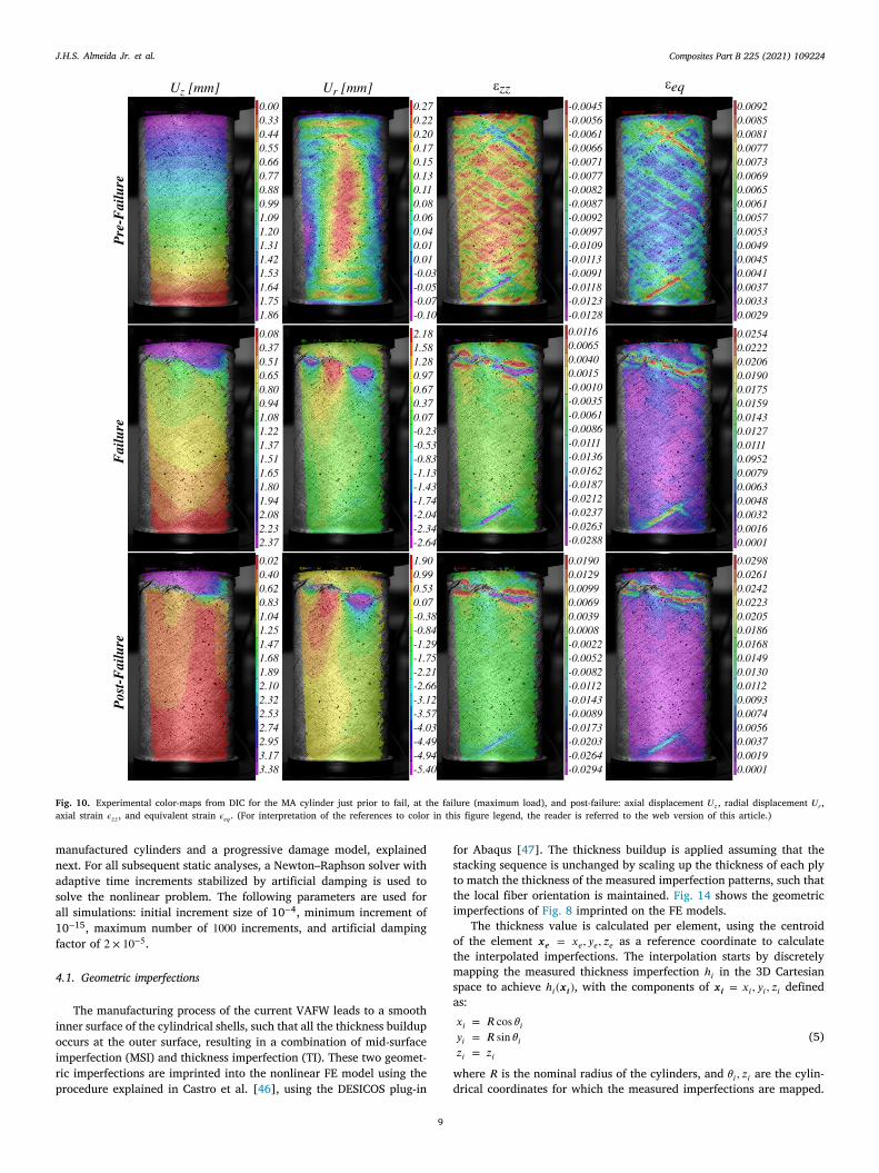
The axial compression tests are assisted by DIC and these resultsare presented in Figs. 10, 11, 12, 13, which are the displacement andstrain fields for the specimens MA–1, CA–2, VAFW4–3, and VAFW8–1,respectively (it is insightful to correlate these results with the load–displacement curves given in Fig. 9. Three load levels are captured andshown in these Figures, namely before failure (pre-failure), at the max-imum compressive load (failure), and post-failure. The characteristicsof each cylinder is next described in detail:
MA cylinder (Fig. 10):
• 𝑈𝑧: the distribution of axial displacement is fairly stable in thelinear region, i.e., at the pre-failure region. Subsequently, thereis a non-linear regime as the cylinder approaches the bifurcationpoint. The cylinder buckles near the top edge as evidenced by thelarge shortening area in purple.
• 𝑈𝑟: Similarly to the axial displacement, the radial displacementmaintains a consistent profile throughout the linear regime of thetest. There is a high level of out-of-plane displacement along thecylinder length, which starts near the edge of the shell. At themaximum load, the structure buckles near the top edge. After fail-ure happens, the shell finds itself into a deep post-buckling state,in which a crack along the tow direction is observed followed bya pronounced localized buckle.
• 𝜖𝑧𝑧: the axial strain provides very useful information since thewinding pattern can be clearly seen, both global strain fieldand local strain concentrations can be identified, which helpsunderstanding how the shell responds to the axially compressiveload. At initial load levels, strain concentrations are observed nearthe edges and along the tows, that is, at the helical cross-overzone (see winding pattern explanations in [42]). At pre-failureplot, which is taken just prior failure, the strain localizes atthe top, near the buckling zone. From these strain field maps,the helical zones create a local strain concentration and can beseen as imperfections on the VAFW cylinders. The effect of theseimperfections together with the measured thickness pattern arediscussed next.

Composites Part B 225 (2021) 109224J.H.S. Almeida Jr. et al.
Fig. 8. Experimentally-measured geometric (thickness) imperfection patterns [32]. The gray areas represent the edges with resin potting. (For interpretation of the references tocolor in this figure legend, the reader is referred to the web version of this article.)
• 𝜖𝑒𝑞 : the equivalent strain map, calculated from the principalstrains 𝜖1 and 𝜖2 as 𝜖𝑒𝑞 =
√
𝜖21 − 𝜖1𝜖2 + 𝜖22 , reveals that stressestend to concentrate around imperfections. At the pre-failure, twopronounced strain concentration areas can be clearly seen at twotow segments near the bottom and top edges (see red areas),which makes the cylinder prone to suddenly buckle in those areas.Then, a strong strain concentration is seen along the buckled areaaround the top edge.
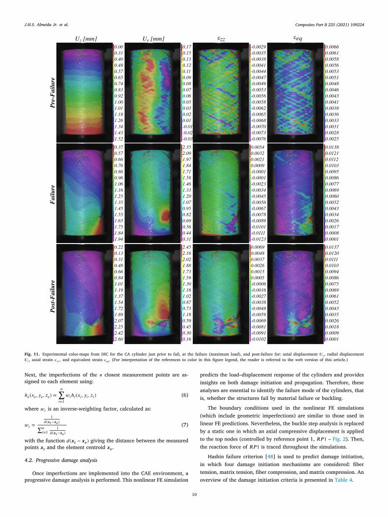
Most of the observations made for the MA cylinders also applyto the CA design since they both have constant-angle configurations.Nevertheless, cylinder CA (Fig. 11) shows strong evidences of materialfailure instead of buckling. Besides, it should be noted that:
• 𝑈𝑧: similar and expected axial displacement prior to failure, vary-ing linearly from top to the bottom of the sample, with a changein form at failure and at post-failure, that is, when the shell isnot able to sustain any load anymore, characterized by higherdisplacement level towards the failure location near the loweredge.
• 𝑈𝑟: the radial displacement varies very slightly around the cir-cumference of the cylinder and reaches maximum levels aroundthe shell mid-length. At failure, a higher radial displacement isfound near the main crack. A similar scenario is identified at thepost-failure.
• 𝜖𝑧𝑧: higher deformation at the helical cross-over imperfection ar-eas and around the edges. At failure, the axial strain concentratesat the lower edge of the specimen, location where the cylinderfails.
• 𝜖𝑒𝑞 : stresses concentrate along the imperfections, but with highermagnitude near the lower edge mainly due to the contribution oftransverse strain 𝜖2.
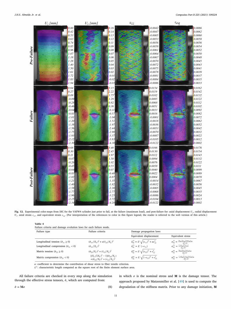
Given that the optimization for the VAFW4 cylinder also provides aconstant-angle fiber path, similar interpretations are inferred (Fig. 12):
7
• 𝑈𝑧: the axial shortening is as expected, in which a change isonly observed after the structure buckles closer to the cylindermid-length.
• 𝑈𝑟: the radial displacement is also very similar, with higher radial(out-of-plane) displacement levels along the shell length. Thelevel of radial displacement for this cylinder is about 20% of theaxial displacement. This behavior is better captured with reducedintegration shell elements, as utilized here, once elements withfull integration might undergo shear and membrane locking and,therefore, the finite elements would be too rigid and certainlythese levels of radial displacement would not be captured.
• 𝜖𝑧𝑧: the same observations are made here, where thickness imper-fections create strain concentrations more prone to buckle thanthe ‘‘regular laminate’’ areas, i.e., the diamond-shapes formedduring manufacturing.
• 𝜖𝑒𝑞 : at pre-failure, this strain field is has some strain concen-trations around the upper and lower edge mainly due to thecontribution of transverse strain. At failure, this strain is consid-erably high at the cylinder mid-length at the local dimple. Thepost-failure equivalent strain field is very similar to the one atfailure, which characterizes a short post-buckling range.
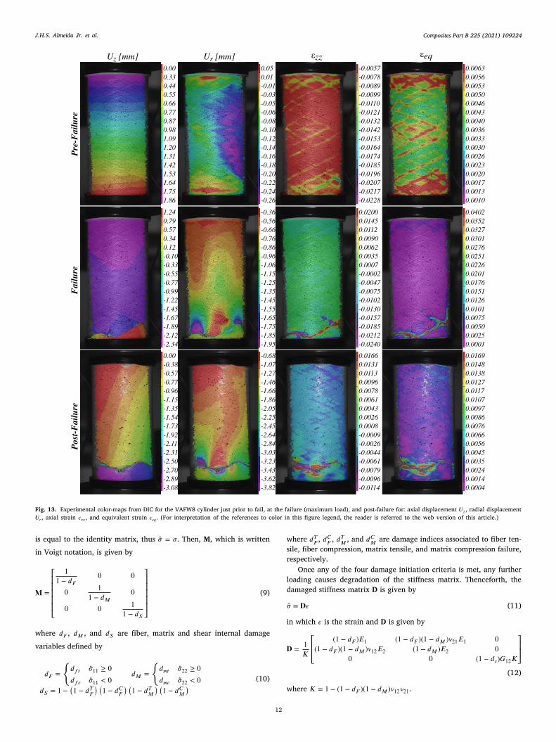
The design VAFW8 (Fig. 13) has a VAFW configuration and adifferent failure mode, i.e. material failure instead of buckling. Furtherobservations are as follows:
• 𝑈𝑧: the axial displacement before failure varies linearly from theupper edge towards the lower one, similarly to the other designs.At failure, large axial displacement levels are seen at the loweredge, where the main crack is located.
• 𝑈𝑟: the radial displacement colored map shows a uniform ra-dial displacement. An interesting characteristic is that the radialdisplacement is higher at the specimen ends. The developmentof membrane stresses after failure suggests a retention of axialstiffness, which can be qualitatively verified at the post-failureregion. Differently than the other family of cylinders, neither dim-ple nor other buckling evidences are identified for this sample,
Composites Part B 225 (2021) 109224J.H.S. Almeida Jr. et al.
Fig. 9. Experimental and numerical load–displacement curves for all cylinders. The plots inside each frame represent the radial displacement field (𝑈𝑟) from FEM and DIC at thefailure (maximum) load. (For interpretation of the references to color in this figure legend, the reader is referred to the web version of this article.)
confirming that any of the material strengths are reached andtherefore the cylinders fails by material failure.
• 𝜖𝑧𝑧: although the axial strain has a similar characteristic, that is,higher strain concentrations in thickness-imperfection areas, themagnitude of the deformations is lower up to 12 kN. Interestingly,after this point, the ‘‘regular laminate’’ areas (diamond-shapedregions) show substantial axial strain accumulation when ap-proaching the failure load. This can be explained by the thicknessbuild-up, which is necessary to produce this configuration ofcylinder, as can be seen in Figs. 6(d) and 1(d). A large and pro-nounced crack along with high levels of axial strain is observednear the lower edge of the cylinder, confirming that bucklingis postponed with the optimization at a sufficient level that thestructure fails by transverse compression instead of experiencingstructural instability.
• 𝜖𝑒𝑞 : the equivalent strain maps are similar to the 𝜖𝑧𝑧 fields, inwhich when the shell approaches the failure load, there is a loadalleviation in the thicker areas and higher deformation within thediamonds. The final failure occurs near the bottom end with amajor crack along the tow direction.
The thickness imperfection patterns of Fig. 8 can be used togetherwith the displacement and strain maps of Figs. 10–13 to better un-derstand the failure mechanism of the FW cylinders. The regions withhigher localized thickness are the helical cross-over zones. Looking at
8
the axial strains (𝜀𝑧𝑧) at compression loads near the onset of failure andcomparing with the out-of-plane displacement (W ) after failure, showthat the failure appear near the helical cross-over zones. This result sup-ports the previous remark that the helical cross-over zones have lowerstrain, and now this lower strain can be attributed to a self-stiffenedregion with a well-defined tow overlap pattern, which is crucial topostpone buckling occurrence. The combination of optimum windingangles for the cylinder VAFW8 with the generated tow overlappingnecessary to make the winding kinematically possible [10] are the mainstructural features and design parameters of the VAFW cylinders toachieve a tailored stiffness and axial compressive performance. Duringthe design of VAFW cylinders one should also focus on optimizing thetow overlapping patterns in order to delay the strain concentration thattriggered the buckling, avoiding geometrically nonlinear degradation ofthe shell in-plane stiffness [45]. This nonlinear stiffness degradation incylinders is very pronounced when the imperfection pattern is orientedcircumferentially, as in the case of axisymmetric imperfections [46].
4. Nonlinear FE modeling
After the design and optimization (Section 2, the cylinders aremanufactured and tested, as shown in Section 3, in which the geometricimperfections of manufactured cylinders are also presented. At thispoint, in order to properly simulate the experimental results, nonlin-ear FE models are built including the geometric imperfections of the
Composites Part B 225 (2021) 109224J.H.S. Almeida Jr. et al.
Fig. 10. Experimental color-maps from DIC for the MA cylinder just prior to fail, at the failure (maximum load), and post-failure: axial displacement 𝑈𝑧, radial displacement 𝑈𝑟,axial strain 𝜖𝑧𝑧, and equivalent strain 𝜖𝑒𝑞 . (For interpretation of the references to color in this figure legend, the reader is referred to the web version of this article.)
manufactured cylinders and a progressive damage model, explainednext. For all subsequent static analyses, a Newton–Raphson solver withadaptive time increments stabilized by artificial damping is used tosolve the nonlinear problem. The following parameters are used forall simulations: initial increment size of 10−4, minimum increment of10−15, maximum number of 1000 increments, and artificial dampingfactor of 2 × 10⁻⁵.
4.1. Geometric imperfections
The manufacturing process of the current VAFW leads to a smoothinner surface of the cylindrical shells, such that all the thickness buildupoccurs at the outer surface, resulting in a combination of mid-surfaceimperfection (MSI) and thickness imperfection (TI). These two geomet-ric imperfections are imprinted into the nonlinear FE model using theprocedure explained in Castro et al. [46], using the DESICOS plug-in
9
for Abaqus [47]. The thickness buildup is applied assuming that thestacking sequence is unchanged by scaling up the thickness of each plyto match the thickness of the measured imperfection patterns, such thatthe local fiber orientation is maintained. Fig. 14 shows the geometricimperfections of Fig. 8 imprinted on the FE models.
The thickness value is calculated per element, using the centroidof the element 𝒙𝒆 = 𝑥𝑒, 𝑦𝑒, 𝑧𝑒 as a reference coordinate to calculatethe interpolated imperfections. The interpolation starts by discretelymapping the measured thickness imperfection ℎ𝑖 in the 3D Cartesianspace to achieve ℎ𝑖(𝒙𝒊), with the components of 𝒙𝒊 = 𝑥𝑖, 𝑦𝑖, 𝑧𝑖 definedas:𝑥𝑖 = 𝑅 cos 𝜃𝑖𝑦𝑖 = 𝑅 sin 𝜃𝑖𝑧𝑖 = 𝑧𝑖
(5)
where 𝑅 is the nominal radius of the cylinders, and 𝜃𝑖, 𝑧𝑖 are the cylin-drical coordinates for which the measured imperfections are mapped.
Composites Part B 225 (2021) 109224J.H.S. Almeida Jr. et al.
Fig. 11. Experimental color-maps from DIC for the CA cylinder just prior to fail, at the failure (maximum load), and post-failure for: axial displacement 𝑈𝑧, radial displacement𝑈𝑟, axial strain 𝜖𝑧𝑧, and equivalent strain 𝜖𝑒𝑞 . (For interpretation of the references to color in this figure legend, the reader is referred to the web version of this article.)
Next, the imperfections of the 𝑛 closest measurement points are as-signed to each element using:
ℎ𝑒(𝑥𝑒, 𝑦𝑒, 𝑧𝑒) =𝑛∑
𝑖=1𝑤𝑖ℎ𝑖(𝑥𝑖, 𝑦𝑖, 𝑧𝑖) (6)
where 𝑤𝑖 is an inverse-weighting factor, calculated as:
𝑤𝑖 =1
𝑑(𝒙𝒊−𝒙𝒆)∑𝑛
𝑖=11
𝑑(𝒙𝒊−𝒙𝒆)
(7)
with the function 𝑑(𝒙𝒊 − 𝒙𝒆) giving the distance between the measuredpoints 𝒙𝒊 and the element centroid 𝒙𝒆.
4.2. Progressive damage analysis
Once imperfections are implemented into the CAE environment, aprogressive damage analysis is performed. This nonlinear FE simulation
10
predicts the load–displacement response of the cylinders and providesinsights on both damage initiation and propagation. Therefore, theseanalyses are essential to identify the failure mode of the cylinders, thatis, whether the structures fail by material failure or buckling.
The boundary conditions used in the nonlinear FE simulations(which include geometric imperfections) are similar to those used inlinear FE predictions. Nevertheless, the buckle step analysis is replacedby a static one in which an axial compressive displacement is appliedto the top nodes (controlled by reference point 1, 𝑅𝑃 1 – Fig. 2). Then,the reaction force of 𝑅𝑃 1 is traced throughout the simulations.
Hashin failure criterion [48] is used to predict damage initiation,in which four damage initiation mechanisms are considered: fibertension, matrix tension, fiber compression, and matrix compression. Anoverview of the damage initiation criteria is presented in Table 4.
Composites Part B 225 (2021) 109224J.H.S. Almeida Jr. et al.
Fig. 12. Experimental color-maps from DIC for the VAFW4 cylinder just prior to fail, at the failure (maximum load), and post-failure for: axial displacement 𝑈𝑧, radial displacement𝑈𝑟, axial strain 𝜖𝑧𝑧, and equivalent strain 𝜖𝑒𝑞 . (For interpretation of the references to color in this figure legend, the reader is referred to the web version of this article.)
Table 4Failure criteria and damage evolution laws for each failure mode.
Failure type Failure criteria Damage propagation laws
Equivalent displacement Equivalent stress
Longitudinal tension (�̂�11 ≥ 0) (�̂�11∕𝑋𝑇 )2 + 𝛼(𝜏12∕𝑆𝐿)2 𝛿𝑓𝑡𝑒𝑞 = 𝐿𝑐√
⟨𝜀11⟩2 + 𝛼𝜀212 𝜎𝑓𝑡
𝑒𝑞 = ⟨𝜎11⟩⟨𝜀11⟩+𝛼𝜏12𝜀12𝛿𝑓𝑡𝑒𝑞 ∕𝐿𝑐
Longitudinal compression (�̂�11 < 0) (�̂�11∕𝑋𝐶 )2 𝛿𝑓𝑐𝑒𝑞 = 𝐿𝑐⟨−𝜀11⟩ 𝜎𝑓𝑐
𝑒𝑞 = ⟨−𝜎11⟩⟨−𝜀11⟩𝛿𝑓𝑐𝑒𝑞 ∕𝐿𝑐
Matrix tension (�̂�22 ≥ 0) (�̂�22∕𝑌𝑇 )2 + (𝜏12∕𝑆𝐿)2 𝛿𝑚𝑡𝑒𝑞 = 𝐿𝑐√
⟨𝜀22⟩2 + 𝜀212 𝜎𝑚𝑡
𝑒𝑞 = ⟨𝜎22⟩⟨𝜀22⟩+𝜏12𝜀12𝛿𝑚𝑡𝑒𝑞 ∕𝐿𝑐
Matrix compression (�̂�22 < 0) [(𝑌𝐶∕2𝑆𝑇 )2 − 1](�̂�22∕𝑌𝐶 )+(�̂�22∕𝑆𝑇 )2 + (𝜏12∕𝑆𝐿)2
𝛿𝑚𝑐𝑒𝑞 = 𝐿𝑐√
⟨−𝜀22⟩2 + 𝜀212 𝜎𝑚𝑐
𝑒𝑞 = ⟨−𝜎22⟩⟨−𝜀22⟩+𝜏12𝜀12𝛿𝑚𝑐𝑒𝑞 ∕𝐿𝑐
𝛼: coefficient to determine the contribution of shear stress to fiber tensile criterion.𝐿𝐶 : characteristic length computed as the square root of the finite element surface area.
All failure criteria are checked in every step along the simulationthrough the effective stress tensors, �̂�, which are computed from:
�̂� = 𝐌𝜎 (8)
11
in which 𝜎 is the nominal stress and M is the damage tensor. Theapproach proposed by Matzenmiller et al. [49] is used to compute thedegradation of the stiffness matrix. Prior to any damage initiation, M
Composites Part B 225 (2021) 109224J.H.S. Almeida Jr. et al.
Fig. 13. Experimental color-maps from DIC for the VAFW8 cylinder just prior to fail, at the failure (maximum load), and post-failure for: axial displacement 𝑈𝑧, radial displacement𝑈𝑟, axial strain 𝜖𝑧𝑧, and equivalent strain 𝜖𝑒𝑞 . (For interpretation of the references to color in this figure legend, the reader is referred to the web version of this article.)
is equal to the identity matrix, thus �̂� = 𝜎. Then, M, which is writtenin Voigt notation, is given by
𝐌 =
⎡
⎢
⎢
⎢
⎢
⎢
⎣
11 − 𝑑𝐹
0 0
0 11 − 𝑑𝑀
0
0 0 11 − 𝑑𝑆
⎤
⎥
⎥
⎥
⎥
⎥
⎦
(9)
where 𝑑𝐹 , 𝑑𝑀 , and 𝑑𝑆 are fiber, matrix and shear internal damagevariables defined by
𝑑𝐹 =
{
𝑑𝑓𝑡 �̂�11 ≥ 0𝑑𝑓𝑐 �̂�11 < 0
𝑑𝑀 =
{
𝑑𝑚𝑡 �̂�22 ≥ 0𝑑𝑚𝑐 �̂�22 < 0
( 𝑇 ) ( 𝐶) ( 𝑇 ) ( 𝐶 )
(10)
12
𝑑𝑆 = 1 − 1 − 𝑑𝐹 1 − 𝑑𝐹 1 − 𝑑𝑀 1 − 𝑑𝑀
where 𝑑𝑇𝐹 , 𝑑𝐶𝐹 , 𝑑𝑇𝑀 , and 𝑑𝐶𝑀 are damage indices associated to fiber ten-sile, fiber compression, matrix tensile, and matrix compression failure,respectively.
Once any of the four damage initiation criteria is met, any furtherloading causes degradation of the stiffness matrix. Thenceforth, thedamaged stiffness matrix D is given by
�̂� = 𝐃𝜖 (11)
in which 𝜖 is the strain and D is given by
𝐃 = 1𝐾
⎡
⎢
⎢
⎣
(1 − 𝑑𝐹 )𝐸1 (1 − 𝑑𝐹 )(1 − 𝑑𝑀 )𝜈21𝐸1 0(1 − 𝑑𝐹 )(1 − 𝑑𝑀 )𝜈12𝐸2 (1 − 𝑑𝑀 )𝐸2 0
0 0 (1 − 𝑑𝑠)𝐺12𝐾
⎤
⎥
⎥
⎦
(12)
where 𝐾 = 1 − (1 − 𝑑 )(1 − 𝑑 )𝜈 𝜈 .
𝐹 𝑀 12 21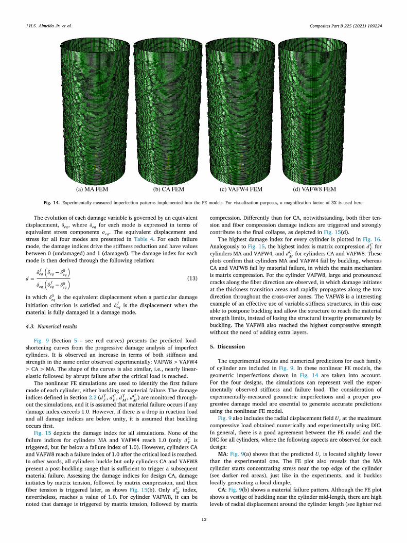
Composites Part B 225 (2021) 109224J.H.S. Almeida Jr. et al.
Fig. 14. Experimentally-measured imperfection patterns implemented into the FE models. For visualization purposes, a magnification factor of 3X is used here.
The evolution of each damage variable is governed by an equivalentdisplacement, 𝛿𝑒𝑞 , where 𝛿𝑒𝑞 for each mode is expressed in terms ofequivalent stress components 𝜎𝑒𝑞 . The equivalent displacement andstress for all four modes are presented in Table 4. For each failuremode, the damage indices drive the stiffness reduction and have valuesbetween 0 (undamaged) and 1 (damaged). The damage index for eachmode is then derived through the following relation:
𝑑 =𝛿𝑓𝑒𝑞
(
𝛿𝑒𝑞 − 𝛿0𝑒𝑞)
𝛿𝑒𝑞(
𝛿𝑓𝑒𝑞 − 𝛿0𝑒𝑞) (13)
in which 𝛿0𝑒𝑞 is the equivalent displacement when a particular damageinitiation criterion is satisfied and 𝛿𝑓𝑒𝑞 is the displacement when thematerial is fully damaged in a damage mode.
4.3. Numerical results
Fig. 9 (Section 5 – see red curves) presents the predicted load-shortening curves from the progressive damage analysis of imperfectcylinders. It is observed an increase in terms of both stiffness andstrength in the same order observed experimentally: VAFW8 > VAFW4> CA > MA. The shape of the curves is also similar, i.e., nearly linear-elastic followed by abrupt failure after the critical load is reached.
The nonlinear FE simulations are used to identify the first failuremode of each cylinder, either buckling or material failure. The damageindices defined in Section 2.2 (𝑑𝑇𝐹 , 𝑑𝐶𝐹 , 𝑑𝑇𝑀 , 𝑑𝐶𝑀 ) are monitored through-out the simulations, and it is assumed that material failure occurs if anydamage index exceeds 1.0. However, if there is a drop in reaction loadand all damage indices are below unity, it is assumed that bucklingoccurs first.
Fig. 15 depicts the damage index for all simulations. None of thefailure indices for cylinders MA and VAFW4 reach 1.0 (only 𝑑𝐶𝐹 istriggered, but far below a failure index of 1.0). However, cylinders CAand VAFW8 reach a failure index of 1.0 after the critical load is reached.In other words, all cylinders buckle but only cylinders CA and VAFW8present a post-buckling range that is sufficient to trigger a subsequentmaterial failure. Assessing the damage indices for design CA, damageinitiates by matrix tension, followed by matrix compression, and thenfiber tension is triggered later, as shows Fig. 15(b). Only 𝑑𝐶𝑀 index,nevertheless, reaches a value of 1.0. For cylinder VAFW8, it can benoted that damage is triggered by matrix tension, followed by matrix
13
compression. Differently than for CA, notwithstanding, both fiber ten-sion and fiber compression damage indices are triggered and stronglycontribute to the final collapse, as depicted in Fig. 15(d).
The highest damage index for every cylinder is plotted in Fig. 16.Analogously to Fig. 15, the highest index is matrix compression 𝑑𝐶𝐹 forcylinders MA and VAFW4, and 𝑑𝐶𝑀 for cylinders CA and VAFW8. Theseplots confirm that cylinders MA and VAFW4 fail by buckling, whereasCA and VAFW8 fail by material failure, in which the main mechanismis matrix compression. For the cylinder VAFW8, large and pronouncedcracks along the fiber direction are observed, in which damage initiatesat the thickness transition areas and rapidly propagates along the towdirection throughout the cross-over zones. The VAFW8 is a interestingexample of an effective use of variable-stiffness structures, in this caseable to postpone buckling and allow the structure to reach the materialstrength limits, instead of losing the structural integrity prematurely bybuckling. The VAFW8 also reached the highest compressive strengthwithout the need of adding extra layers.
5. Discussion
The experimental results and numerical predictions for each familyof cylinder are included in Fig. 9. In these nonlinear FE models, thegeometric imperfections shown in Fig. 14 are taken into account.For the four designs, the simulations can represent well the exper-imentally observed stiffness and failure load. The consideration ofexperimentally-measured geometric imperfections and a proper pro-gressive damage model are essential to generate accurate predictionsusing the nonlinear FE model.
Fig. 9 also includes the radial displacement field 𝑈𝑟 at the maximumcompressive load obtained numerically and experimentally using DIC.In general, there is a good agreement between the FE model and theDIC for all cylinders, where the following aspects are observed for eachdesign:
MA: Fig. 9(a) shows that the predicted 𝑈𝑟 is located slightly lowerthan the experimental one. The FE plot also reveals that the MAcylinder starts concentrating stress near the top edge of the cylinder(see darker red areas), just like in the experiments, and it buckleslocally generating a local dimple.
CA: Fig. 9(b) shows a material failure pattern. Although the FE plotshows a vestige of buckling near the cylinder mid-length, there are highlevels of radial displacement around the cylinder length (see lighter red

Composites Part B 225 (2021) 109224J.H.S. Almeida Jr. et al.
Fig. 15. Monitoring of all four damage indices throughout the simulations for every cylinder.
Fig. 16. Plot of the most critical damage mode after failure for every cylinder. (For interpretation of the references to color in this figure legend, the reader is referred to theweb version of this article.)
areas), which concentrate stress and is mainly dominated by matrixcompression. The DIC pattern shows high radial displacement at thelower part of the cylinder, and it should be pointed out that evidencesof buckling were found at the backside of the area covered by the DICcameras, therefore not shown here.
VAFW4: These simulated and experimental patterns (Fig. 9(c)) aresimilar in terms of location and mode. Two major dimples are seen inthe middle of the cylinder, but with different displacement magnitudes.The greater dimples are shown in both cylinders in blue, whereas theless-pronounced one are seen in light red in the FE pattern, and in redin the DIC pattern.
VAFW8: FE and DIC 𝑈𝑟 fields for this cylinder (Fig. 9(d)) are inreasonable agreement. The failure pattern of this design strongly differsfrom the other three cylinders. Looking at the numerical 𝑈𝑟 field, thereis a large and pronounced crack along the fiber direction, which beginsat the cylinder mid-length and propagates towards its lower edge. Thisis also observed in the DIC measurements, where a crack at the samelocation starts on the backside of the cylinder (region not coveredby DIC cameras) and propagates towards the cylinder lower edge. Nobuckling evidence has been observed for the VAFW8 specimen.
The maximum compressive load (𝐹𝐶 ), stiffness (𝐾 — calculated ata shortening level of 1mm), and absorbed energy (𝐸 — calculated byintegrating each curve) for all configurations are compiled in Table 5.Although all calculated parameters increase in the following order MA< CA < VAFW4, they do not differ statistically. Nevertheless, cylinderVAFW8 shows a significant enhancement for all three comparison pa-rameters, which corroborates the great potential of VAFW fiber path toimprove the performance of composite shells under axial compression.
14
Table 5Average maximum compressive load, stiffness, and absorbed energy, and the respectivestandard deviations: Experimental and predicted values.
Design 𝐹𝐶 [kN] 𝐾 [kN∕mm] 𝐸 [J]
Exp. Num. Dif. Exp. Num. Dif. Exp. Num. Dif.
MA 11.8 ± 1.4 11.9 0.8% 5.8 ± 0.1 5.9 1.4% 14.6 ± 3.9 13.3 9.6%CA 12.5 ± 0.8 13.0 4.2% 5.9 ± 0.4 5.9 3.6% 14.3 ± 1.3 13.9 2.4%VAFW4 13.5 ± 1.1 14.2 4.7% 6.4 ± 0.4 6.4 0.2% 17.9 ± 7.0 16.0 11.7%VAFW8 20.5 ± 3.8 21.8 6.4% 8.5 ± 1.4 8.5 3.3% 25.7 ± 6.1 27.2 5.6%
Relative difference (Dif.) = (|Exp. − Num.|) ×100/Num.
In terms of absolute properties, as per Table 5, its average experimentalcompressive strength is 74%, 64%, and 52% higher than the MA, CA,and VAFW4 cylinders, respectively. This is a strong indication thatappropriately varying the fiber orientation can enhance the distributionof stresses when approaching the bifurcation point.
Table 5 also presents the predictions from the nonlinear FE modelswith progressive damage and imperfections incorporated. Generallyspeaking, all predictions are within the standard deviation from exper-imental values, which demonstrates the high fidelity achieved by thedeveloped models. In terms of maximum compressive load, the highestrelative difference between numerical predictions (Num. in Table 5)and experimental results (Exp. in Table 5) are of 6.4%, whereas thedifference for the MA cylinder is only 0.8%. As expected, the stiffnesspredictions are even closer to the experimental measurements, in whichthe highest difference is of 3.3% for the VAFW8 design, and as lowas 0.2% for the VAFW4 cylinder. A similar panorama is seen for the
Composites Part B 225 (2021) 109224J.H.S. Almeida Jr. et al.
Table 6Average experimental and predicted specific properties.
Design 𝐹 𝑆𝐶 [kN∕g] 𝐾𝑆 [kN∕mm g] 𝐸𝑆 [J∕g]
Exp. Imp. Num. Imp. Exp. Imp. Num. Imp. Exp. Imp. Num. Imp.
MA 0.080 – 0.080 – 0.039 – 0.040 – 0.099 – 0.090 –
CA 0.086 7.4% 0.089 11.2% 0.040 3.1% 0.042 5.5% 0.098 −1.3% 0.085 5.7%VAFW4 0.091 13.6% 0.095 18.3% 0.043 9.6% 0.043 8.3% 0.120 21.2% 0.107 19.0%VAFW8 0.124 55.8% 0.132 64.4% 0.052 31.5% 0.053 34.1% 0.156 57.4% 0.165 82.7%
Imp.: = Improvement in relation to cylinder MA.
Fig. 17. Imperfection sensitivity (knockdown) curves for all cylinders.
absorbed energy, where the largest difference of 11.7% is observed forthe VAFW4 cylinder.
In order to compare the calculated mechanical properties for thedifferent cylinders using a better basis, the properties are normalizedusing the mass of each cylinder, given in Table 3. The calculatedspecific properties are presented in Table 6. For maximum specificcompressive force (𝐹𝑆
𝐶 ), specific stiffness (𝐾𝑆 ), and specific absorbedenergy (𝐸𝑆 ), the highest improvements are always for the cylinderVAFW8. This confirms that the amount of material placed in this designis not decisive in its properties, but instead the variable-angle fiberconfiguration that provides an effective fiber distribution that enhancethe compressive strength of the VAFW8 shell.
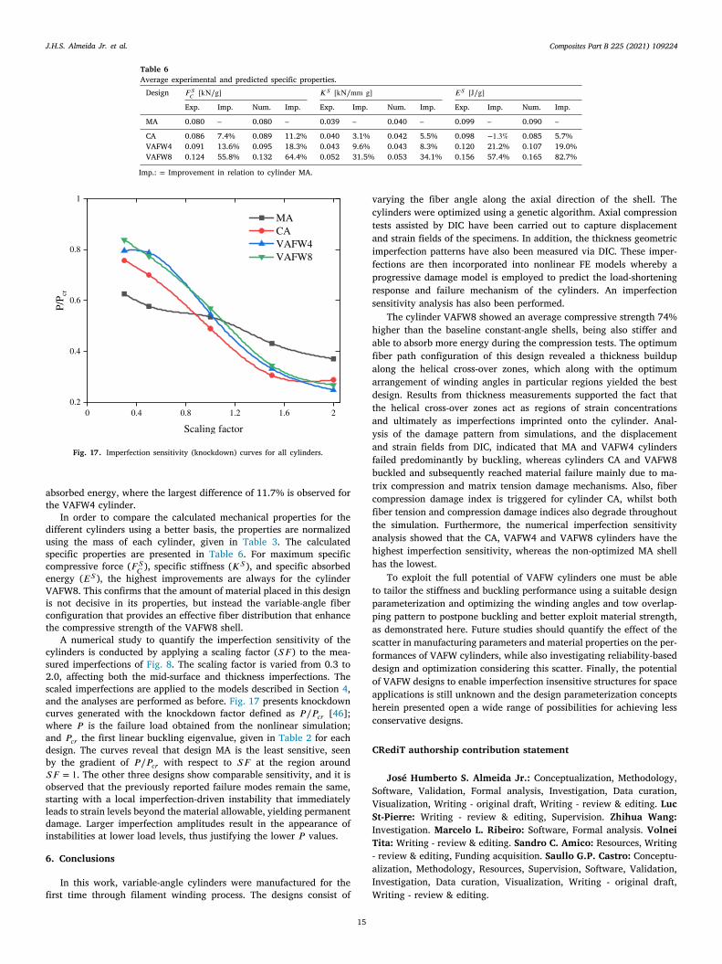
A numerical study to quantify the imperfection sensitivity of thecylinders is conducted by applying a scaling factor (𝑆𝐹 ) to the mea-sured imperfections of Fig. 8. The scaling factor is varied from 0.3 to2.0, affecting both the mid-surface and thickness imperfections. Thescaled imperfections are applied to the models described in Section 4,and the analyses are performed as before. Fig. 17 presents knockdowncurves generated with the knockdown factor defined as 𝑃∕𝑃𝑐𝑟 [46];where 𝑃 is the failure load obtained from the nonlinear simulation;and 𝑃𝑐𝑟 the first linear buckling eigenvalue, given in Table 2 for eachdesign. The curves reveal that design MA is the least sensitive, seenby the gradient of 𝑃∕𝑃𝑐𝑟 with respect to 𝑆𝐹 at the region around𝑆𝐹 = 1. The other three designs show comparable sensitivity, and it isobserved that the previously reported failure modes remain the same,starting with a local imperfection-driven instability that immediatelyleads to strain levels beyond the material allowable, yielding permanentdamage. Larger imperfection amplitudes result in the appearance ofinstabilities at lower load levels, thus justifying the lower 𝑃 values.
6. Conclusions
In this work, variable-angle cylinders were manufactured for the
15
first time through filament winding process. The designs consist of
varying the fiber angle along the axial direction of the shell. Thecylinders were optimized using a genetic algorithm. Axial compressiontests assisted by DIC have been carried out to capture displacementand strain fields of the specimens. In addition, the thickness geometricimperfection patterns have also been measured via DIC. These imper-fections are then incorporated into nonlinear FE models whereby aprogressive damage model is employed to predict the load-shorteningresponse and failure mechanism of the cylinders. An imperfectionsensitivity analysis has also been performed.
The cylinder VAFW8 showed an average compressive strength 74%higher than the baseline constant-angle shells, being also stiffer andable to absorb more energy during the compression tests. The optimumfiber path configuration of this design revealed a thickness buildupalong the helical cross-over zones, which along with the optimumarrangement of winding angles in particular regions yielded the bestdesign. Results from thickness measurements supported the fact thatthe helical cross-over zones act as regions of strain concentrationsand ultimately as imperfections imprinted onto the cylinder. Anal-ysis of the damage pattern from simulations, and the displacementand strain fields from DIC, indicated that MA and VAFW4 cylindersfailed predominantly by buckling, whereas cylinders CA and VAFW8buckled and subsequently reached material failure mainly due to ma-trix compression and matrix tension damage mechanisms. Also, fibercompression damage index is triggered for cylinder CA, whilst bothfiber tension and compression damage indices also degrade throughoutthe simulation. Furthermore, the numerical imperfection sensitivityanalysis showed that the CA, VAFW4 and VAFW8 cylinders have thehighest imperfection sensitivity, whereas the non-optimized MA shellhas the lowest.
To exploit the full potential of VAFW cylinders one must be ableto tailor the stiffness and buckling performance using a suitable designparameterization and optimizing the winding angles and tow overlap-ping pattern to postpone buckling and better exploit material strength,as demonstrated here. Future studies should quantify the effect of thescatter in manufacturing parameters and material properties on the per-formances of VAFW cylinders, while also investigating reliability-baseddesign and optimization considering this scatter. Finally, the potentialof VAFW designs to enable imperfection insensitive structures for spaceapplications is still unknown and the design parameterization conceptsherein presented open a wide range of possibilities for achieving lessconservative designs.
CRediT authorship contribution statement
José Humberto S. Almeida Jr.: Conceptualization, Methodology,Software, Validation, Formal analysis, Investigation, Data curation,Visualization, Writing - original draft, Writing - review & editing. LucSt-Pierre: Writing - review & editing, Supervision. Zhihua Wang:Investigation. Marcelo L. Ribeiro: Software, Formal analysis. VolneiTita: Writing - review & editing. Sandro C. Amico: Resources, Writing- review & editing, Funding acquisition. Saullo G.P. Castro: Conceptu-alization, Methodology, Resources, Supervision, Software, Validation,Investigation, Data curation, Visualization, Writing - original draft,
Writing - review & editing.
Composites Part B 225 (2021) 109224J.H.S. Almeida Jr. et al.
Declaration of competing interest
The authors declare that they have no known competing finan-cial interests or personal relationships that could have appeared toinfluence the work reported in this paper.
Acknowledgments
This research is partially funded by a FAPESP/FAPERGS, Brazilgrant (project numbers 19/2551 and 2019/15179-2); The authorsthank CSC – IT Center for Science, Finland, for computational re-sources; Z. Wang thanks China Scholarship Council; We thank H. Floresfor his assistance with manufacturing; We thank D. Ruijtenbeek, J.Boender, V. Horbowiec, F. Bosch and B. Grashof and J. G. Alvarezfor their great support, and for all the team involved of the amazingAerospace Structures and Materials Laboratory (DASML) at TU Delft.
References
[1] Huang Z, Qian X, Su Z, Pham DC, Sridhar N. Experimental investigation anddamage simulation of large-scaled filament wound composite pipes. CompositesB 2020;184:107639. http://dx.doi.org/10.1016/j.compositesb.2019.107639.
[2] Almeida Jr JHS, Faria H, Marques A, Amico S. Load sharing ability of theliner in type III composite pressure vessels under internal pressure. J Reinf PlastCompos 2014;33(24). http://dx.doi.org/10.1177/0731684414560221.
[3] Perillo G, Grytten F, Sørbø S, Delhaye V. Numerical/experimental impact eventson filament wound composite pressure vessel. Composites B 2015;69:406–17.http://dx.doi.org/10.1016/j.compositesb.2014.10.030.
[4] Cui Z, Liu Q, Sun Y, Li Q. On crushing responses of filament windingCFRP/aluminum and GFRP/CFRP/aluminum hybrid structures. Composites B2020;200:108341. http://dx.doi.org/10.1016/j.compositesb.2020.108341.
[5] Almeida Jr JHS, Tonatto ML, Ribeiro ML, Tita V, Amico SC. Buckling and post-buckling of filament wound composite tubes under axial compression: Linear,nonlinear, damage and experimental analyses. Composites B 2018;149:227–39.http://dx.doi.org/10.1016/j.compositesb.2018.05.004.
[6] Gemi L, Köklü U, Yazman Ş, Morkavuk S. The effects of stacking sequenceon drilling machinability of filament wound hybrid composite pipes: Part-1mechanical characterization and drilling tests. Composites B 2020;186:107787.http://dx.doi.org/10.1016/j.compositesb.2020.107787.
[7] Stedile Filho P, Almeida Jr JHS, Amico SC. Carbon/epoxy filament woundcomposite drive shafts under torsion and compression. J Compos Mater2018;52(8):1103–11. http://dx.doi.org/10.1177/0021998317722043.
[8] Wang Q, Li T, Wang B, Liu C, Huang Q, Ren M. Prediction of void growth andfiber volume fraction based on filament winding process mechanics. ComposStruct 2020;246:112432. http://dx.doi.org/10.1016/j.compstruct.2020.112432.
[9] Rafiee R. On the mechanical performance of glass-fibre-reinforced thermosetting-resin pipes: A review. Compos Struct 2016;143:151–64. http://dx.doi.org/10.1016/j.compstruct.2016.02.037.
[10] Wang Z, Almeida Jr JHS, St-Pierre L, Wang Z, Castro SGP. Reliability-basedbuckling optimization with an accelerated kriging metamodel for filament-woundvariable angle tow composite cylinders. Compos Struct 2020;254:112821. http://dx.doi.org/10.1016/j.compstruct.2020.112821.
[11] Wang Z, Almeida, Jr. JHS, Ashok A, Wang Z, Castro SGP. Lightweight designof variable-angle filament-wound cylinders combining kriging-based metamod-els with particle swarm optimization. 2021, http://dx.doi.org/10.31224/osf.io/3ym95, Preprint.
[12] Almeida Jr JHS, Bittrich L, Spickenheuer A. Improving the open-hole tensioncharacteristics with variable-axial composite laminates: Optimization, progres-sive damage modeling and experimental observations. Compos Sci Technol2020;185:107889. http://dx.doi.org/10.1016/j.compscitech.2019.107889.
[13] Kim BC, Potter K, Weaver PM. Continuous tow shearing for manufacturingvariable angle tow composites. Composites A 2012;43(8):1347–56. http://dx.doi.org/10.1016/j.compositesa.2012.02.024.
[14] Chauncey Wu K, Turpin JD, Gardner NW, Stanford BK, Martin RA. Structuralcharacterization of advanced composite tow-steered shells with large cutouts.In: 56th AIAA/ASCE/AHS/ASC structures, structural dynamics, and materialsconference. American Institute of Aeronautics and Astronautics Inc.; 2015, http://dx.doi.org/10.2514/6.2015-0966.
[15] Gürdal Z, Olmedo R. In-plane response of laminates with spatially varyingfiber orientations: Variable stiffness concept. AIAA J 1993;31(4):751–8. http://dx.doi.org/10.2514/3.11613.
[16] Guimarães TAM, Castro SGP, Cesnik CES, Rade DA. Supersonic flutter and buck-ling optimization of tow-steered composite plates. AIAA J 2018;57(1):397–407.http://dx.doi.org/10.2514/1.J057282.
[17] Castro SGP, Donadon MV, Guimarães TA. ES-PIM applied to buckling of variableangle tow laminates. Compos Struct 2019;209:67–78. http://dx.doi.org/10.1016/j.compstruct.2018.10.058.
16
[18] Hao P, Liu C, Yuan X, Wang B, Li G, Zhu T, et al. Buckling optimization ofvariable-stiffness composite panels based on flow field function. Compos Struct2017;181:240–55. http://dx.doi.org/10.1016/j.compstruct.2017.08.081.
[19] Hao P, Yuan X, Liu C, Wang B, Liu H, Li G, et al. An integrated frameworkof exact modeling, isogeometric analysis and optimization for variable-stiffnesscomposite panels. Comput Methods Appl Mech Engrg 2018;339:205–38. http://dx.doi.org/10.1016/j.cma.2018.04.046.
[20] Hao P, Wang Y, Ma R, Liu H, Wang B, Li G. A new reliability-based designoptimization framework using isogeometric analysis. Comput Methods Appl MechEngrg 2019;345:476–501. http://dx.doi.org/10.1016/j.cma.2018.11.008.
[21] Hao P, Liu D, Wang Y, Liu X, Wang B, Li G, et al. Design of manufacturablefiber path for variable-stiffness panels based on lamination parameters. ComposStruct 2019;219:158–69. http://dx.doi.org/10.1016/j.compstruct.2019.03.075.
[22] Tatting BF. Analysis and Design of Variable Stiffness Composite Cylinders inEngineering Mechanics. Tech. rep., Virginia Tech; 1998, http://hdl.handle.net/10919/29313.
[23] Blom AW, Stickler PB, Gürdal Z. Design and manufacture of a variable-stiffnesscylindrical shel. Tech. rep., SAMPE Europe; 2009, p. 1–8, URL https://repository.tudelft.nl/islandora/object/uuid%3A0d8a5de7-966a-4f80-bc5c-bc6bb1733410.
[24] Blom AW, Rassaian M, Stickler PB, Gürdal Z. Modal testing of a compositecylinder with circumferentially varying stiffness. In: Collection of technical pa-pers - AIAA/ASME/ASCE/AHS/ASC structures, structural dynamics and materialsconference. American Institute of Aeronautics and Astronautics Inc.; 2009, p.1–15. http://dx.doi.org/10.2514/6.2009-2558.
[25] Blom AW, Stickler PB, Gürdal Z. Optimization of a composite cylinder underbending by tailoring stiffness properties in circumferential direction. CompositesB 2010;41(2):157–65. http://dx.doi.org/10.1016/j.compositesb.2009.10.004.
[26] Blom AW. Structural performance of fiber-placed, variable-stiffness compositeconical and cylindrical shells (Ph.D. thesis), TU Delft; 2010, p. 1–260, http://resolver.tudelft.nl/uuid:46f2e44b-1a68-44f8-9633-79490a54e087.
[27] Wu KC, Tatting BF, Smith BH, Stevens RS, Occhipinti GP, Swift JB, et al.Design and manufacturing of tow-steered composite shells using fiber placement.In: Collection of technical papers - AIAA/ASME/ASCE/AHS/ASC structures,structural dynamics and materials conference. American Institute of Aeronauticsand Astronautics Inc.; 2009, http://dx.doi.org/10.2514/6.2009-2700.
[28] Wu KC, Stanford BK, Hrinda GA, Wang Z, Martin RA, Alicia Kim H.Structural assessment of advanced composite tow-steered shells. In: 54thAIAA/ASME/ASCE/AHS/ASC structures, structural dynamics, and materialsconference. 2013, http://dx.doi.org/10.2514/6.2013-1769.
[29] White SC, Weaver PM, Wu KC. Post-buckling analyses of variable-stiffnesscomposite cylinders in axial compression. Compos Struct 2015;123:190–203.http://dx.doi.org/10.1016/j.compstruct.2014.12.013.
[30] Wu KC, Farrokh B, Stanford B, Weaver P. Imperfection insensitivity analysesof advanced composite tow-steered shells. In: 57th AIAA/ASCE/AHS/ASC struc-tures, structural dynamics, and materials conference. Reston, Virginia: AmericanInstitute of Aeronautics and Astronautics; 2016, http://dx.doi.org/10.2514/6.2016-1498.
[31] Rouhi M, Ghayoor H, Fortin-Simpson J, Zacchia TT, Hoa SV, Hojjati M. Design,manufacturing, and testing of a variable stiffness composite cylinder. ComposStruct 2018;184:146–52. http://dx.doi.org/10.1016/j.compstruct.2017.09.090.
[32] Castro SGP, Almeida Jr JHS, St-Pierre L, Wang Z. Measuring geometricimperfections of variable–angle filament–wound cylinders with a simple digitalimage correlation (DIC) set up. Compos Struct 2021;114497. http://dx.doi.org/10.1016/j.compstruct.2021.114497.
[33] Vertonghen L, Castro SG. Modelling of fibre steered plates with coupled thicknessvariation from overlapping continuous tows. Compos Struct 2021;113933. http://dx.doi.org/10.1016/j.compstruct.2021.113933.
[34] Almeida Jr JHS, Souza SD, Botelho EC, Amico SC. Carbon fiber-reinforced epoxyfilament-wound composite laminates exposed to hygrothermal conditioning. JMater Sci 2016;51(9):4697–708. http://dx.doi.org/10.1007/s10853-016-9787-9.
[35] Barbero EJ, Cosso FA, Roman R, Weadon TL. Determination of material pa-rameters for abaqus progressive damage analysis of E-glass epoxy laminates.Composites B 2013;46:211–20. http://dx.doi.org/10.1016/j.compositesb.2012.09.069.
[36] Castro SGP, Mittelstedt C, Monteiro FA, Arbelo MA, Ziegmann G, Degenhardt R.Linear buckling predictions of unstiffened laminated composite cylinders andcones under various loading and boundary conditions using semi-analytical mod-els. Compos Struct 2014;118(1):303–15. http://dx.doi.org/10.1016/j.compstruct.2014.07.037.
[37] Castro SGP, Donadon MV. Assembly of semi-analytical models to address linearbuckling and vibration of stiffened composite panels with debonding defect.Compos Struct 2017;160:232–47. http://dx.doi.org/10.1016/j.compstruct.2016.10.026.
[38] Almeida Jr JHS, Bittrich L, Nomura T, Spickenheuer A. Cross-section optimiza-tion of topologically-optimized variable-axial anisotropic composite structures.Compos Struct 2019;225. http://dx.doi.org/10.1016/j.compstruct.2019.111150.
[39] Kogiso N, Watson LT, Gürdal Z, Haftka RT. Genetic algorithms with localimprovement for composite laminate design. Struct Optim 1994;7(4):207–18.http://dx.doi.org/10.1007/BF01743714.
Composites Part B 225 (2021) 109224J.H.S. Almeida Jr. et al.
[40] Dalibor IH, Lisbôa TV, Marczak RJ, Amico SC. Optimum slippage dependent,non-geodesic fiber path determination for a filament wound composite nozzle.Eur J Mech A Solids 2020;82:103994. http://dx.doi.org/10.1016/j.euromechsol.2020.103994.
[41] Zu L, Koussios S, Beukers A. Shape optimization of filament wound ar-ticulated pressure vessels based on non-geodesic trajectories. Compos Struct2010;92(2):339–46. http://dx.doi.org/10.1016/j.compstruct.2009.08.013.
[42] Lisbôa TV, Almeida Jr JHS, Dalibor IH, Spickenheuer A, Marczak RJ, et al.The role of winding pattern on filament wound composite cylinders under radialcompression. Polym Compos 2020;41(6):2446–54. http://dx.doi.org/10.1002/pc.25548.
[43] Castro SGP, Almeida Jr JHS. VAFW cylinders 2020, S1, S2, S4, S8, DIC rawdata, Version 2021-03-16; 2021. http://dx.doi.org/10.5281/zenodo.4608398.
[44] Castro SGP, Almeida Jr JHS. VAFW cylinders 2020, S1, S2, S4, S8, stitchedimperfections, Version 2021-03-04; 2021. http://dx.doi.org/10.5281/zenodo.4581164.
17
[45] Croll JG. Towards a rationally based elastic-plastic shell buckling design method-ology. Thin-Walled Struct 1995;23(1–4):67–84. http://dx.doi.org/10.1016/0263-8231(95)00005-X.
[46] Castro SG, Zimmermann R, Arbelo MA, Khakimova R, Hilburger MW, De-genhardt R. Geometric imperfections and lower-bound methods used tocalculate knock-down factors for axially compressed composite cylindrical shells.Thin-Walled Struct 2014;74:118–32. http://dx.doi.org/10.1016/j.tws.2013.08.011.
[47] Castro SGP, Reichardt J, Lozano E. DESICOS plug-in for abaqus. Version 2.4.13.2021, http://dx.doi.org/10.5281/zenodo.4506587.
[48] Hashin Z. Fatigue failure criteria for unidirectional fiber composites. J Appl MechTrans ASME 1981;48(4):846–52. http://dx.doi.org/10.1115/1.3157744.
[49] Matzenmiller A, Lubliner J, Taylor RL. A constitutive model for anisotropicdamage in fiber-composites. Mech Mater 1995;20(2):125–52. http://dx.doi.org/10.1016/0167-6636(94)00053-0.