Embed Size (px)
Citation preview

; .. •:. ;-*fo;.y 'fewer Grime
EUUCNOIS*>j:jB.Ui>.mr

UNIVERSITY OF ILLINOIS
LIBRARY
Class Book Volume
•ail


DESIGN OF A 150-TON ROTARYTOWER CRANE
BY
JOHN KARMAZIN
PAUL FRED POPP
THESIS
FOR THE
DEGREE OF BACHELOR OF SCIENCE
IX
MECHANICAL ENGINEERING
COLLEGE OF ENGINEERING
UNIVERSITY OF ILLINOIS
1911

UNIVERSITY OF ILLINOIS
THIS IS TO CERTIFY THAT THE THESIS PREPARED UNDER MY SUPERVISION BY
Q^ctAjut ^t^6 Qj&Lji/:.
S O J^y
sJ o-ut^w C/T^y^^~y
ENTITLED
IS APPROVED BY ME AS FULFILLING THIS PART OF THE REQUIREMENTS FOR THE
DEGREE OF ^3oU^Z-/ fl^f tfou^cV
APPROVED:
(Q , 6L. ^tcU^z£n/Instructor in Charge.
(^Csizc*jp HEAD OF DEPARTMENT OF .^^^^ .C^p***^**^
1

Digitized by the Internet Archive
in 2013
http://archive.org/details/designof150tonro00karm

Contents
Chapter I - Types of Rotary Tower CranesArt . Page
1 Types _-_-_________-___--___- 4
Chapter II - General Dimensions
2 Determination of Dimensions _________ 5
3 Loads ----------------------- 5
4 Speeds- ---------------------- 6
Chapter III - Specifications
5 Trolley 7
6 Structure _ _ _ - 8
Unit Stresses and Proportions of Parts- ______ 8
Chapter IV - The Trolley
8 Design of 150-Ton Hook- -___-_---_____ 10
9 60-Ton Crane Hook __--_____-__--_-_ 13
10 Design of Hook Thrust Bearing ----------- 16
11 Size of Sheave Pin for 150-Ton Load ______ 17
12 Size of Sheave Pin for 60-Ton Load -------- 17
13 Design of Sheaves ----------------- 18
14 Design of Block Pin ---_-_--_-_-_-__ 18
15 Size of Block Plates- _-_--__--_-____ 19
16 Design of Trolley Block ________-_-_-_ 20
17 Rope Tensions ------------------- 22
18 Size of Rope- ------------------- 23
19 Diameter of Drums ----------------- 24
20 Horse-power of Motors --------------- 24
21 Design of Drum Gear and Pinion- ---------- 27
22 Drum Gear and Pinion - 60-Ton ----------- 28


23 Design of Worm- ------------------ 29
24 Design of Worm Shaft- --------------- 29
25 Design of Worm Gear Shaft ------------- 31
26 Design of Drum- ------------------ 32
27 Design of Drum Shaft- --------------- 34
28 Design of Double Block Brake- ----------- 35
29 Design of Trolley Frame ------------ 37
30 Design of Main Girder of Trolley Frame- ------ -37
51 Design ofTrolley Frame Columns- ---------- 40
32 Design of Trolley Motor Platform- --------- 41
33 Design of Gross Beam for Support of Worm Gear Shaft 42
34 Design of Supporting Beams for Trolley Block- - - - 43
35 Design of the Racking Mechanism ---------- 44
36 Size of Motor ------------------- 46
37 Design of Gears for Racking Mechanism ------- 47
38 Design of Shafts for Racking Mechanism- ------ -49
39 Design of Trolley Wheel Axle- ----------- 50
40 Weight of Trolley ----------------- 51
Chapter V - The Structure
41 Theory of the Structure -------------- 52
42 Stability of the Structure- ------------ 54
43 Stresses in the Rotary Jib- ------------ 58
44 Tower Stresses ------------------ 63


DESIGN OF A 150-TON
ROTARY TOWER CRANE
Introduction
The work of construction in ship building yards as well
as the unloading of vessels at the docks requires the handling
of very heavy masses. In order to convey these loads either on
or off board the ships, special cranes have been designed for
this purpose
In the United States the cantilever traveling gantry
crane is used almost exclusively for dock and ship building work
while England and Germany have recently introduced a new type
of crane, namely, the rotary tower crane. The first crane of
this kind was built in Germany in 1903 with a capacity of 150
tons. Another crane of the same capacity and of German design
was erected in England in 1906. It was very natural for English
designers to attempt an improvement over the German crane, and
this vas accomplished the following year by building the tower
columns perpendicular instead of tapering them inward from the
bottom to the top. The center column of the German crane was
replaced by a large roller path directly on top of the tower.
The principal advantage of the English crane over the German is
its lower cost particularly the cost of erection, since no false


work is required. The German crane on the other hand has a more
pleasing appearance and shows greater stability and more careful
design. The greater complexity of the German crane as a problem
of design has been the chief reason for selecting that type as a
thesis.
It is the purpose of this thesis to design a 150-ton
rotary tower crane and present the subject not in complete detail
but in such a manner as to show the method of analysing the va-
rious forces acting on such a structure and the determination of
the stresses due to these forces.


-3-


-4-
Chapter I.
Types of Rotary Tower Cranes
1. There are at present four types of rotary tower
cranes in use, as follows:
1. Hammer type, in common use in Germany
(a) Rectangular tower
(b) Tripod tower
2, English type,- jib supported on top, roller path
5. Rotary column type- entire crane revolves
4. Traveling rotary tower type- German type
The hammer type of crane was chosen for this design
for reasons stated in the introduction. The determination of the
class of web bracing is of course a matter of choice with the en-
gineer. Practice shows a wide variation in the type of truss
used and it appears as if the choice is influenced by the perso-
nal desires of the designer more than by any other factor. In
the case at hand the single Warren truss was used for both the
lateral and vertical systems and the double Warren type with
v e rticals for the outside and center towers.


-5-
Chapter II
General Dimensions
2. Determination of dimensions - The conditions under
which a crane is to operate determine very largely its general
dimensions. The height is fixed by the masts of the ships, and
the radius at which the maximum load is to "be lifted by practical
considerations such as the width of the vessel and the range in
which the crane can revolve efficiently under maximum load. In
this design the length of the radius was arbitrarily chosen.
The distance center to center of main trusses was made equal to
the center distances between trolley wheels. The depth of the
truss and panel length were so chosen as to procure an economical
design of section and retain a pleasing appearance. The base
dimensions of the outside tower were determined from the princi-
ples of stability. Fig. 1 gives the important dimensions of the
structure a few of which are given below:
Available lift ISO feet
Radius ?/ith maximum load 110 feet
Radius with minimum load 110 feet
3. Loads -
Main lift 150 tons
Auxiliary 60 tons
Wind on upper chord £50 pounds per lineal foot
V/ind on lower chord 8 50 pounds per lineal foot
Wind on the tower - 100 pounds per vertical linealfoot


-6-
The weight of the trolley was computed after the
design was made and will be given in tabulated form in the follow-
ing pages. The dead load of the tower and revolving jib had to
be assumed, however the assumptions made were based upon the
weights of cranes of the same capacity as the one under conside-
ration and are fairly accurate. The weight of the revolving jib
of 210 tons was evenly distributed over the lower panel points
as shown on the stress sheet Fig. 36 which produced a load of
20000 pounds at each panel point. None of this dead load was
applied to the panel points of the center column because the me-
thod of distributing all the load over the truss gives slightly
larger stresses in the tower columns and avoids unnecessary re-
finement.
The dead load of the outside tower of 100 tons was
distributed proportionately among the panel points with increas-
ing loads from top to bottom. Stress sheet Fig. 38 shows the
magnitude and application of the loads.
4. Speeds- Speed of hoisting (150 tons)- 3 feet perminute
Speed of hoisting ( 60 tons) -18 feet perminute
Racking speed ------- 25 feet perminute
Slewing speed ------- One revolutionin ten minutes


-?-
Chapter III
Specifications
5. Trolley - The trolley will be of the Gteel frame
type of rigid construction. All bearings shall have ample bearing
area with bronze bushings on all main shafts.
Drum - The drum shall be machine grooved and of am-
ple size for the rope used and to permit of full hoist without
overlapping of ropes.
Brakes - The hoist sliall be equipped with two brakes,
a mechanical load brake and an automatic solenoid electrical
brake. Both brakes shall be capable of holding the load inde-
pendently.
Gears - All gears except the drum and pinion are cut
from the solid from good gray iron or cast steel. Pinions are
cut from forged steel blanks.
Shafting - All large shafts to be forged steel,
small shafts of co^d rolled.
Hook and Block - To be of the Hess-Bright ball-
bearing type carrying a heavy hook of refined steel* Block
sheaves to be of ample diajneter for the rope used and to have
turned grooves. The sheaves to be fitted with bronze bushings.
Factor of Safety - All parts of the trolley to be
designed so that the maximum unit stresses shall not exceed
the following values:
Tension - - - - ------ 16000 lbs. per so. in.
Compression 16000 " w " "

-e-
Shear --- — - ___ 10000 lbs. per sq. in.
Bearing (journal) - - - 1500 to 3000 " "
Bearing (stationary surface) 24000 lbs. per sq.in.
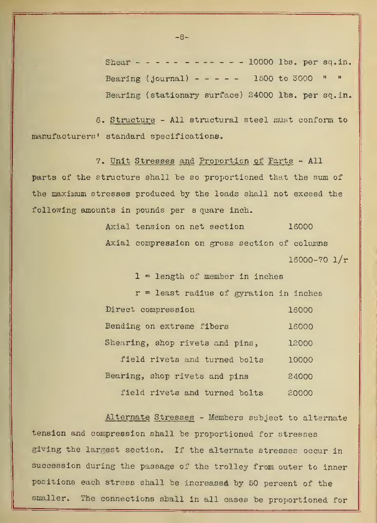
6. Structure - All structural steel must conform to
manufacturers' standard specifications.
?. Unit Stresses and Proportion of Farts - All
parts of the structure shall be so proportioned that the sum of
the maximum stresses produced by the loads shall not exceed the
following amounts in pounds per s quare inch.
Axial tension on net section 16000
Axial compression on gross section of columns
16000-70 1/r
1 = length of member in inches
r = least radius of gyration in inches
Direct compression 16000
Bending on extreme fibers 16000
Shearing, shop rivets and pins, 12000
field rivets and turned bolts 10000
Bearing, shop rivets and pins 24000
field rivets and turned bolts 20000
Alternate Stresses - Members subject to alternate
tension and compression shall be proportioned for stresses
giving the largest section. If the alternate stresses occur in
succession during the passage of the trolley from outer to inner
positions each stress shall be increased by 50 percent of the
smaller. The connections shall in all cases be proportioned for


-9-
the sum of tlie stresses. For the details of design any standard
"bridge specifications may "be folio/zed preferably those of the
"American Railway Engineering and Maintenance of Way Asnociation'.'


-10-
Chapter IV
ine irolley
8. Design of 150 Ton Hook
The double hook type was selected since it is bet-
ter adapted to heavy loads.
Load 300,000 pounds
Unit stress tension 16000 lb. per sq.in.
Area required at bottom of thread
500,000 ,„ ntr- 18. 7fa sq.in.16,000
Dia. - 5"
Use U.S.S. Thread 6 threads per inch
Dia. at root = 5.0 inches
Outside dia. = 5. $5 inches
The maximum stress in a double crane hook according
to Bach is:
S = Q, sin<r Q x Q x a ^2 A 2 A r 2zAr r-a
S = unit stress lb. per sq.inch
Q = total load in lb.
CC m angle section taken makes with the vertical
A - area of section
X = distance to center of gravity of section
r - radius of curvature of gravity axis
a = distance to extreme fiber
b - one half of the short diameter of the ellipse
I f &z °*
A J r +\ ^


-11-
z for an elliptical section has the followingvalue
1 .a. 2 1 .a. 4 5 ,a6 ...Z =
4(7 5
8 <7>+ —4 {V * - - (2)
sin oC m .32
A = fTa. b = /T6 x 3 = 56.5 sq. inches
1, 6,
8 1, 6,
4 5,
6N
6z =
4( 18
) +a
<
18) +
64(
18}
= .086
Substituting these values in (1) above, we have
m 150000 x .52 _ 150000 x 5.75
56.5 56,5 X 18
+ 150000 x 5.75 6
.026 x 56.5x18 18-6
= + 16300 lb. per sq.in.
Fig. 2 shows in detail the dimensions of the hook
inally adopted for 150 ton capacity


o

-15-
9. 60 Ton Crone Hook
The type of hook selected for this capacity is not
the same as shown in Fig. 2, "but of the ordinar y form in common
use in this country
Load 120,000 pounds
Unit tensile Strength 16000 lb. per sq.in.
Area required at bottom of thread
120,000 m *7 R an 4*= - a= 7,5 sq. in.16,000
Dia. =3.1 inches
Use U.S.S. Thread 6 threads per inch
Dia. at root =3,1 inch
Outside dia. = 3.35 inch
Maximum stress in crane hook according to Bach is
Q _ Q.(a + eg) _ Q(a + eP ) qA Ar zAr r + q
a = distance shown on sketch
eg= distance from center of gravity to extreme
fiber in tension
distance from center of gravity to extreme
fiber in compression
\ = distance to any fiber
z = - i f'-^- dA
Other symbols as in previous article
The follov/ing are values for a trapezoidal section
see Fig. 3.


-14-
b + bi
3 1/4+9 5/4A = —
= 65 sq. inches
h b + Z bje2
=3 b + bi
10
h - e2
a + eg
h •= 8 a
b =Fig. 3.
-1 +8 r b-bi
bx +— (ej+r)J loge—A -(b-bx ))(4)i* ^g
r+e-
(b + bi)h
Taking above proportions we have:
eg 5/6 a r ll/6 a
and the expression for z reduces to l/z = 10. 27
Substituting the above values in equation (3),
we have:
S - -10.8? - — — 5)A 11/6 a +\
For Y£ * -eg equation (5) reduces to
S.
s
! + 8.56 -7t A
- 3.99 I
(6)
(7)
For the 60 ton hook the line of action of Q is 5
inches from inside of hook.
bx = 3 1/4 inches; b - 9 3/4 inches; h = 10 inches
A = 65 sq. inches


-15-
St
- + 8.56 - + 15900 lb. per square inch
180000Sc
* - 3.99 ——— - - 75 50 Id. per square inch
The dimensions fir ally selected for this capacity
are shown in Fig. 4.
Fig. 4.


-16-
10. Design of Hook Thrust Bearing
The type of thrust bearing selected is shown in
Fig. 5. The dimensions shown in this figure apply to the bearing
selected for the 150 ton hook, and were obtained from the Hess-
Bright Co. catalog. It is knc n as their "Medium 1100 Series"
Fig. 5.
For the 60 ton hook a bearing similar to the one shown
in Fig. 5 will be used, and the following are the dimensions:
Inside diameter 9 l/4 inches
Outside diameter 13 9/l6 inches
Thickness of height 3 3/4 inches
Diameter of ball 1 5/8 inches
No. of balls 34
-17-
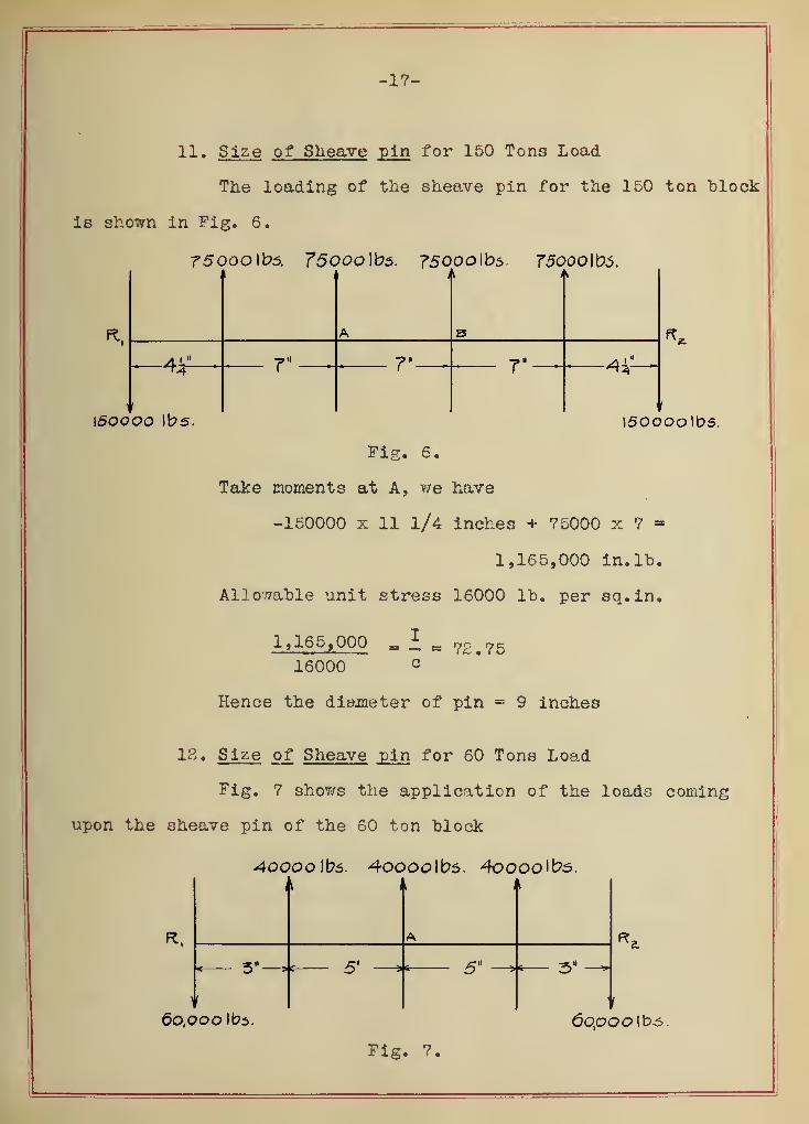
11. Size of Sheave pin for 150 Tons Load
The loading of the sheave pin for the 150 ton block
is shown in Fig. 6.
75ooo lbs. ?5ooo lbs. 75000 lbs 750oo\k><>.
Ft
\5oooo lbs.
7" -4i
isoooolbs.
Fig. 6.
Take moments at A, we have
-150000 x 11 1/4 inches + 75000 x 7 -
1,165,000 in. lb.
Allowable unit stress 16000 lb. per sq.in.
1,165,000 _ £ m 7£#7516000
Hence the diameter of pin = 9 inches
18. Size of Sheave pin for 60 Tons Load
Fig, 7 shows the application of the loads coming
upon the sheave pin of the 60 ton block
AOOOo\bs. 4oooolbs. 4oooolb5.it A A
3"^»* 5'
60,000 lbs.
5" —+— 3" -
6opoo \ b.s.
Fig. 7.


-18-
Take moments at A, we have
-60000 x 15 + 40000 x 5 - 600,000 in. lb.
Allowable unit stress 16000
600.000 I p.i = — = O ( • t)
16,000 c
Hence the diameter of pin = 7 l/4 inches
13. Design of Sheaves
150 Ton Block
Diameter of sheaves 3 ft. 6 in.
Length of hub 7 in.
Allowable unit bearing pressure 2000 lbs.
Actual bearing pressure = 75000 «- (7x9)
1900 lb. per sq.in.
60 Ton Block
Diameter of sheaves 22 in.
Length of hub 5 in.
Allowable unit bearing pressure 2000 lbs.
Actual bearing pressure 88 40000 (5 x 7 1/4)
1100 lbs. per sq.in.
14. Design of Block Pin
The load acting upon the block pin for both the
150 ton and 60 ton capacities will be assumed as concentrated
at the center, as shown in Fig. 8, which figure applies to the
150 ton block.


-19-
500000 lbs.
« \4$— ^ 14$"
i
«
!
>
150000 lbs. I50ooo lbs.
Fig. 8.
The maximum bending moment
M = 150,000 x 14 3/4 = 2,312,000 lb. in.
2,212,000 = I m 83016000 e
i
Diameter of pin =9 3/8 inches at center
Size of pin in bearings
Allowable unit shear 10000 lb.
Actual shear = 150,000 lb.
150, 000 M . . .
, ' ^ - 15 sq.in. reauired10,000
Diameter - 4 l/S inches
60 Tons
By a similar line of procedure the following di-
mensions of the 60 ton block pin are f ound:
Diameter of Pin =5 5/8 inches at center
Diameter of Pin in bearings - 2 7/8 in.
15. Size of Block Plates
150 Tons
Allowable unit bearing s tress 20000 lbs.
P = 300,000
300,000Area = = 15 sq.in.
20,000


-20-
Diameter of pin 4 l/Z in.
t = plate thickness
2t x 4 1/2 - 15
t - 1.67 say 1 3/4 in.
60 Tons
Thickness of Plate = 1 l/8 in.
16. Design of Trolley Block
150 Tons - Trolley Sheave Pin
In Fig. 9 are shown all the loads acting upon this
pin, and they will be considered as concentrated at the center
of the sheave bearings.
8>54oo)t>s. ?spoo\ba, &5A-oo\\?s.
8"- 6" 54-
\ZA4-oo\be. \-R44oo\ti&.
Fig. 9.
Taking moments at A, we have
124,400 x 13 1/2 - 85400 x 8 = 996,000 in. lb.
996,000 m I m 62<316,000 c
Diameter = 8 l/2 in.
Bearing pressure on sheave pin
8 5,400 tora iv *— = 1250 lb. per sq.in.68
Allowable = 2000


Size of Plate
Allowable bearing pressure 20,000 lb. per sq.in.
124,400Area required 20,000 6,22 sq.in.
t = thickness or plate
8 1/2 t - 6.22
t = 3/4 in.
60 Tons - Trolley Sheave Pin
The loading of the pin is shov/n in Fig. 10, and treat
ing it in a manner similar to that given above, we find the maxi
mum bending moment as
M - 42800 x S = 128,400 lb. in.
128,400 m I m 8
16,000 c
Diameter = 4 15/16 in.
4^,80O IDS. 4-2.8OO IbS.
3-
42.SOO lbs, 42.,8oo{bs.
Fig. 10.
Thickness of plate = l/s in.


17. Rope TensionB - The arrangement of the hoisting rope
for the 150 ton block is shown diagrammatically in Fig. 11. As-
sume the coefficient k as 1.06. The weight of the hook and block
is 12000 pounds, hence the total load to be raised is 312000
pounds.
T. T, X I X
As
3\zooo lbs.
Fig. 11.
From the theory of rope stiffness we have the following equation:
-
m _ 156000 (k-1)4 "
—= 156000 (.06)
.264
= 25450 pounds
T = T4k3 = 35450 x 1.06
2 = 42300 pounds
T, = Tg = 42300 pounds
The value 42300 fixes the size of rope used in this case.
For the 60-ton lift the arrangement of the hoisting rope
is shown in Fig. 12.


X
mi mT,
12.4,8 oo lbs
Fig. 12.
In this case the weight of the block is 4800 pounds which makes the
load to be raised as 124800. The value of k will be assumed the
same as above. By a similar line of reasoning used above, we find
the following values:
T3
= 19600 pounds
T6
= T. = 22200 pounds
The rope must be made large enough to resist this pull of 22200
pounds.
18. Size of Rope - 150-Ton Block
From Art. 17 the rope tensions T-j^ and Tgwere found
to be 42300 pounds, which requires the use of a 1 2/4 inch plough
steel rope. The following table gives additional data applying to
this rope.
Diameter Weight Average safe Weight Length
of Pove per working in in
inches Foot stress- lb. lb. ft.
1 3/4 4.85 51200 6500 1333

-24-
60-Ton Elock- From Art. 17 the rope tensions T,
and T_ were found to be 22200 pounds. This requires a 1 l/4 inch6
plough steel rope. The following table gives further data pertain-
ing to the rope selected.
Diameter
of rope
inches
Weight
per
foot
Average safe
working
load
Weight
in
lb.
Length
in
ft.
1 1/4 2.45 26800 2475 1010
19. Diameter of Drums - 150-^Ton. Practice shows that the
diameter of a crane trolley drum is about 30 times the rope diame-
ter. Since the rope is 1 3/4 inches a drum 5 feet in diameter is
chosen. The amount of rope to be wound on the drum is 150 x 4 or
600 feet.
Pitch of grooves = 2 in.
Number of turns n = 600/5K = 38.2
Length of drum assuming three extra turns is 7 feet.
60-Ton - For the 6^ ton load a much smaller rope is
required and consequently a smaller drum, but for practical reasons
this drum will be made the same diameter as the 150-ton drum. The
amount of rope to be wound on the drum is 150 x 3 or 450 feet.
Pitch of grooves = 1.5 in,
Again assuming three extra turns the length is 4 feet.
20. Horse-power of Motors - The size of the motors re-
quired is determined from the load and speed with which it is to
be hoisted. The following gives the method of procedure:
Efficiency of rope = 95 percent


-25-
Efficiency of each pair of gears = 96 percent
Efficiency of worm gear = 45 percent
Efficiency of motor = 80 percent
Speed = 3 feet per minute
Combined efficiency of rope and gears = 41.5percent
H.P. = 42500 x 12 = 37.1
.415 x 33000
37 1Actual H.P. = *— = 46.40
.8
Each motor must deliver 2/3 x 46.40 = 30.9 H.P.
The neares't commercial size of motor that can be used
is one rated at 40 H.P. at 400 R.P.H. Assuming the speed of the
rope as 12 feet per minute, the gear ratio between the motors and
thedrum will have to be
400 x 15.7
12= 522
Upon careful consideration as to the system of gearing best sui-
ted for driving the drum, the German method of worm gear drive
will be selected. It has the advantage of being a much lighter
and simpler mechanism than the spur gear drive which for such
heavy loads would require exceedingly massive gears. Fig. 13
shows a diagrammatic arrangement of the mechanism. Assume the
diameter of the gear on the drum as 7 ft. 6 in. and that of the
pinion 15 in.


I I I T
]r i
Fig. 13.


-27-
21. Design of Drum Gear and Pinion - 150-Ton. The load
coming upon the teeth of the main gear and pinion in this case is
as follows:
Load W = 42300 x 50 _ 2 9400 pounds. 96 x 45
The velocity of the gear teeth is
——— x 7.5 x 3.1415.7
or approximately 18 feet per
minute. As a trial substitution in the Lewis formula, assume
the following:
p = 1; p» = 3.142; y = 0.072; n = 15; D = 15 in.
S for steel casting = 19000: f = 7 in.
W = Sp'fy
29400 = 19000 x 3.142 x 7 x 0.072
29400 1 30080 lb.
For all practical purposes this is a close enough agreement, hence
the above dimensions will be used. Making the gear of the same
material it will be unnecessary to investigate it for strength
as the pinion is always the weaker.
Worm Gear- The load coming upon the worm gear is
as follows:
. . _ 29400 x 7.5 ^ >rt ^Load W = = 4240 lb.17.31 x 3
rr 1 ,4 3 - 14 x 34.62 x 4.6 _ _Velocity = = 41.7 it. per mm.12
Assume y = 0.11; f = 2 3/4 in.; p1 = 1.25 in.
S for bronze = 11500; substituting these values
in the Lewis formula we get:

-28-
4240 = 11500 x 1.25 x 2.75 x 0.11
/ 4350
The agreement is close enough hence the dimensions assumed will
be used. The diameter of the gear is 34 5/8 inches and the num-
ber of teeth 87.
22. Drum Sear and Pinion - 60-Ton. For this lighter
load assume a rope spe id of 54 feet per minute. The gear ratio
between the motors and the drum will necessarily be
400 x 15.7 _- 11654
Assume the diameter of the gear on the drum as 5 ft. 3 in., that
of the pinion as 42 inches, and the load coming upon the teeth
of the gear and pinion is as follows:
Load W = 2S200 x 50 _ 22000 lb..96 x 31.5
As a trial substitution in the Lewis formula assume the following:
pf = 1.57; p = 2; n = 84; f = 6.75; y = .113
S for steel casting = 18500 lb.
22000 = 18500 x .113 x 6.75 x 1.57
1 22200
The agreement is sufficient, hence the assumed dimensions will be
used. The diameter of the pinion is 42 inches and the number of
teeth 84.
The gear is made of the same material which will make
an investigation for its strength unnecessary because the pinion
is always the weaker.


-29-
25. Design of Worm - The motor is capable of transmit-
ting 40 H.P. at 400 R.P.M., hence the twisting moment coming upon
the worm shaft is
o - 65050 HF n
= 6305 lb. inches
Assume oc = 4° tana = .0699
u ! = .05 ~\/l -f .072 x . 989 = 0.052
Worm 1 l/4w pitch 75° involute teeth
Force transmitted to gear at pitch line
F =29400 * 7 - 5 " = 4250*
» 17.50 x 5
P. Diameter of Worm gear = 54.62 M
1.255.14 x .07
= -/ ( P' + 2^Kr\8JTr - ^'p'
P. Diameter of Worm = = 5.7"
P =
= 566 lb.
PQ= 298
" P " 566 " 52,5/5
S m Wtan^
1 - jll' tanoo
= 4665 = 1140 lb.1 - .052 x .07
24. Design of Worm Shaft - A diagram of the forces
acting on the worm shaft is shown in Fig. 14. The horizontal
thrust is neutralized by the right and left hand worms.
R1
= 1140 lb.


-30-
Ra = ~^ 11408 + 566'
= 1210
<l—Q -si*
R,
P= 566 lbs.
6
R>
52"-
-52-04"-
6"-
P=566)t?5.
-6-
Fig. 14.
The maximum bending moment is
1210 x 6 = 7260 lb. in.
Substituting in Guest's Law, we have
MQ
= "^630?
9620
+ 7260^ - 9620 lb. in
= 2.4 = I4000 c
Diameter of shaft = 2 7/8 in.


-31-
25. Design of Worm Gear Shaft - The forces acting upon
the worm gear shaft are shown in Fig. 15.
^4oolb5..44oolb5..44oo(b5. s94-oo lbs.
3=
Fig. 15.
The shaft is continuous over three supports and the reactions
are determined according to the theorem of three moments as fol-
lows:
"lh + 2M2(1
1+ V + «Va =^ PlH
6<k
l" k
l3
)
V22(2k2 - 3k
22 +k
23)
2 Mg(42 + 110.75) = -4400 x 422
( . 143 - .143 3 )
Mg = -3560
Since there are three forces acting there will be three values
of k, hence by applying the above theorem three times the total
moment at the second support is
-3560 - 9550 - 5775 = - 18885
42 Ei ~ 4400(6 - 21 - 36) = -18885
= 6150
Maximum bending moment is 6150 x 6 = + 36900 in. lb. 3y a similar
method of procedure the reaction and moment due to the load of


-32-
29400 pounds are found to be
2 M (42 + 110.75) = -29400 x 110. 752 (2 x .88 - 3 x .88s
^ + .883 J
Mg = -130000
110.75 R3- 29400 x 97.75 = -130000
R3
= +24800 lb.
Bending moment is 24800 x 13 = 322000 lb. in.
Twisting moment is 29400 x 75 = 222000 lb. in.
M = 392000 lb. in.e
I _ 592000 _ 24< 5c 16000
Diameter of shaft = 6 l/4 inches
26. Design of Drum - The drum must be strong enough to
withstand the bending moment due to the forces acting shown in
Fig. 16 and in addition those due to its own weight; furthermore
it must be stiff enough so that deflection will not exceed 0.01
of an inch. A thickness of shell will be assumed and investiga-
ted for maximum unit stress. The fiber stress found to be 168
pounds per square inch is very low but further investigation for
deflection as shown in the following calculations reconciles the
assumed thickness.
Max. M_ takes place with load at center
MB= Wl/4
42300 x 84
4
= 890,000 lb. in.
MT= 42300 x 30
= 1,269,000 lb. in.


-33-
42300 lbs.
Fig. 16.
= y 1269.02 + 390. 2
= 1,550,000 lb. in.
1*550,000 = <0 98j
d4 - 4j
= .098'604 - 524
'
l 60
= 168 lb. per sq.inch
3
A = (P - -W)8 48 EI
W = 20000 I = .049 (d4 - d
x
4) = 2770
= (42300 - §20000) —8 48 x 15000000 x 2770
= .0168 inch Note : Deflection governs de-
sign. The drum will be ribbed in various places to decrease this
deflection
.


-34-
27. Design of Drum Shaft - The drum is fitted with
bronze bushings and turns freely upon the stationary shaft thus
eliminating the twisting moment on the shaft. Fig. 17 shows the
forces which act on the shaft.
Fig. 17.
Load on tooth acting 30° with horizontal 29400 lb.
30° component at A = ~S940 .
Q. (110.75 - 13)
110.75
= 25950 lb.
V - 5000 x 97.75 + 42300 x 90.75 + 15000 x 52A '
——110.75
= 46200 lb.
By combining graphically the two forces acting at A as shown in
Fig. 18 we have as a resultant AR= 27000 lb. and the bending mom-
ent due to this force

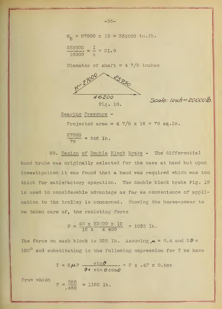
-35-
M_ = 27000 x 15 = 351000 in. lb.B
351000 I nm ^mm mm- — 21,9
16000 c
Diameter of shaft = 4 7/8 inches
* 6 a°° Sca/e: //nc/t= 20000/6.Fig. 18.
Bearing Pressure -
Projected area = 4 7/8 x 16 - 78 sq.in.
27000= 346 lb.
78
28. Design of Double Block Brake - The differential
band brake was originally selected for the case at hand but upon
investigation it was found that a band was required which was too
thick for satisfactory operation. The double block brake Fig. 19
is used to considerable advantage as far as convenience of appli-
cation to the trolley is concerned. Knowing the horse-power to
be taken care of, the resisting force
m 40_x 55000 x 12 =12 x x 400
The force on each block is 525 lb. Assuming /i = 0.4 and 2d
-
120° and substituting in the following expression for T we have
T = 2/UP sin£ = 2 x .4P x 0.585d+ sin 6 cosO
from which <-0(-
P = £££ = 1120 lb..468


-37-
By taking moments about the pin joint k becomes
kx
20 + 525 x 2.5 - 8 x 1120 =
k x= 383
k2
= 514
By taking moments about the fulcrum of the lever for the value of
k we have
k 24 = 3(k]_
+ kg)
= 3 x 897
k = 112
29. Design of Trolley Frame - According to specifica-
tions the trolley frame is to be of the rigid frame steel type.
Fig. 20 shows such a type of trolley frame. It is composed of
riveted structural steel members, the sections of which are de-
termined directly from the forces to which they are subjected.
The following gives a rigid design of each member.
30. Design of Main Girder of Trolley Frame - An exact
determination of the forces which act on the main girder of the
trolley frame would involve laborious mathematical calculations
hence for all practical purposes certain assumptions were made in
regard to the distribution of the load coming upon the eight co-
lumns and therefore upon the girders. The forces shown in Fig. 21
are those finally arrived at. The reactions are found to be
n _ 3.3 x 92950 + 13.25 x 92950 - 3 x3750 +2600 xl8.86Kl
16
= 98700 lb.
Ro = 93550 lb. from which the maximum bending moment i

-58-
Trolley FrameFig. 20.


-39-
Z600\bs. 9S950)b5.
-9-11-
9^950)D5.
5.C ^-i
5?j50lb5.
-0"
R.
16^4,
.o
Fig. 21,
6.25 x 3750 - 3.25 x 93550 = 280,580 pound-feet
M _ I _ 280580 x 12 = 21QS c 16000
The following table gives the properties of the section
assumed and shows the section to be sufficient.
Ho.
Area
in
sq . in
.
h I Ah2
I' I
c
1 12 576 576
1 12 576
*T 10.87 3.45 355 358. 5
2 •7 10.87 3.^5 355 358. 5216.5
2 10 . 87 355 358. 5
o 3 10.87 3.45 355 358. 5
Maximum shear is 98700 lb.


-40-
98700Required, area = = 9.87 sq.in.
10000
Actual area in shear is 10.1 sq.in.
31. Design of Trolley Frame Columns - By a careful
analysis of the forces acting on the columns it becomes evident
that the horizontal thrust on the drum bearings produces a bend-
ing moment in the columns. The complex cross framing does not
permit a thorough rational design hence the columns will be de-
signed only for direct stress.
Columns No. 1 and 5 -
Load on each column 2600 lb.
Length = 7 ft. 2 l/2 in.
. 3,6 and 7
.
Fig. 22.
a rational design is unnecessary due to the very
small load, then minimum size channels will be used and these
will be in excess of the area required by the load. Use 2-3in.-
4 lb. channels. Tie channels together at appropriate places with
3/8" batten plates. Fig. 22 shows the arrangement of the section
Columns i
Maximum load 52200 lb
.
Length = 7 ft.
Least l/r = 125r lg • (do .
Try 2 - 6" - 8.0 lb. channels. Area =4.7 sq.in
Least r = 2.33 l/r = 36
S 16000 - 70 l/r
= 13480 lb. per sq.in.
52200Required area = — — = say 4 sq.in.13480
Use 2 - 6" - 8.0 lb. channels


-41-
BP
Fig. 23 shows the arrangement of the section.
Co limns No. 4and 8
Load 5750 lb
.
Length 7 ft.
Try 2-3" - 4 lb . channels
Area = 2.58 sq.in.
Least r = 1.17 l/r =71.9
S = 16000 - 70 l/r
as 10967 Fig. 24.
3750Required area = — = .34 sq.in.
10967
Use 2 - 3" - 4 lb. channels as shown in sketch.
For reasons of construction use 2 - 6" - 8 lb. channels. Channels
are placed as shown in Fig. 24.
32. Design of Trolley Motor Platform - The motor pre-
sents the simple case of the cantilever beam Fig. 25 with a maxi-
mum bending moment= 1900 x 48 = 91200 lb. in.
1900
1
1>5. 1050 |t>5.
4&
\CHA(NNELT"x gjgjb
Fig. 25.
S 16000
91200 _ 5,7 .= I16000 " ' c
Use a 7" - 9 3/4 lb. channel

-42-
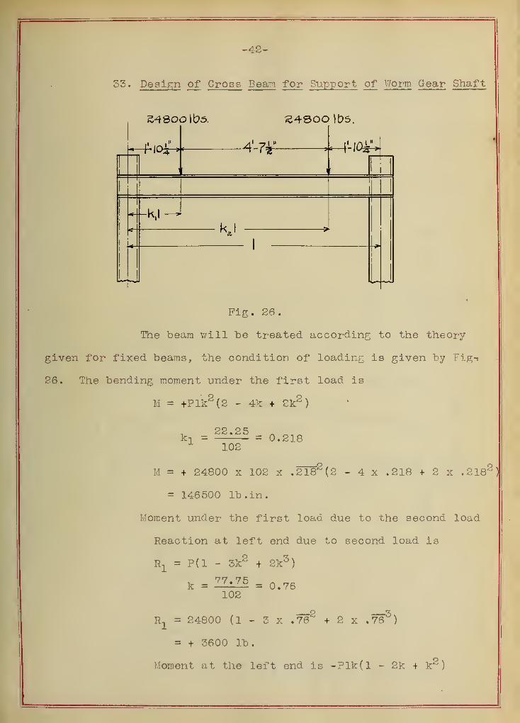
53. Design of Cross Beam for Support of Worm Gear Shaft
z^eoo Wo5. )t>5,
I -in4-7*
Fig. 26.
The beam will be treated according to the theory
given for fixed beams, the condition of loading is given by Fig-
26. The bending moment under the first load is
M = +Plk2 (2 - 4k + 2k2 )
k n = = 0.218
M = + 24800 x 102 x .2182(2 - 4 x .218 + 2 x .218*
= 146500 lb. in. •
Moment under the first load due to the second load
Reaction at left end due to second load is
Rj = P(l - 3k2 + 2k5 )
k = 77 ' 75 = 0.76102
R1
= 24800 (1 - 3 x .762
+ 2 x .765
)
= + 3600 lb.
Moment at the left end is -Plk(l - 2k + k^
)


-43-
M = -24800 x 102 x ,76(1 - 2 x .76 + .762
)
= -110,000 lb. in.
The moment under the first load due to the second
load is: +3600 x 22.25 - 110000 = - 29000 lb. in.
Maximum moment is
+ 146500 - 29000 = + 117500 lb. in.
117500 = 7.3516000
M I =S
"c
Use 2 - 5W - 9 lb. channels
34. Design of Supporting Beams for Trolley Block- Beam
for 150-Ton Load.- The plate girders shown in Figs. 27and 28
will be used to support the trolley block.
8
A4-' 8
I
JLsectionA A
l
Fig. 27.
II = 62200 x 56 1/2
= 3,510,000 lb. in.
£,510,000 = 219>5 = I
16000
Value of — = 222 for the section shown abovec

V

-44-
, , . . . 124400 _ ,„ AAArea required in shear at the pin is
10QQq'
"
sq • in •
Actual area in shear is 23.6 sq.in.
^ • 124400 _ 1<3 ,
Area required to take end shear is10000
Actual area in shear is 17.0 sq.in.
sq .m
.
124400Required bearing area of pin =
gQQQQ- 6.22 sq.m.
Actual area = 5.30 sq.in.
Rivet a 1/2 in. plate to the side of the girder
around the pin hole.
Beam for 60-Ton Load
<0 2 we£> P/afe
a L <?"
Fig. 28.
35. Design of the Racking Mechanism - Before the design
of the racking mechanism can be made it is necessary to determine
the total frictional resistance due to the load imposed upon the
trolley wheels. The size of trolley wheels according to Ernst
is given as follows: Total load on the wheels is 200 tons.
The trolley shown diagrammatically in Fig. 29 has 8 wheels, each
wheel taking a load of 25 tons. The width of rail is given by
the following equation:
b = Q
CD
Q,^ = load per wheel
C = constant = 540


-45-
of rail
k
D = diameter of wheel
Assuming a diameter of 56 inches we have as a width
b = 50000
540 x 36
= 2.57 inches say 2 9/l6 inches
The wheel proportions are given in Fig. 30.
5b4-
6b4
Fig. 30
Fig. 29.
Weight of 4 standard rails 100 ft. long = 1132 lb.
Knowing the size of trolley wheels and the loads,
the resistance due to rolling friction is obtained from the equa-
tion: DF = c—
•
r
where c = constant for rolling friction (.02)
r = radius of wheel
50000F = .02—
= 555 lb.
Total = 555 x 8
= 4440 lb.


to
The flange friction is taken as 2$ of total load
400000 x .02 = 8000 lb.
Force required to Overcome Journal Friction
Diameter of journal 4 5/8 in.
fM = .1 R = 2 5/16
M = 2 5/16 x .1 x 50000 11550 in . lb
.
Total moment = 8 x 11550 = 92400 in . lb
.
92400Force at radius r = —j-g— = 5135 lb.
Total Force to overcome Friction
Journal Friction ----- 5135 pounds
Flange " - - - - - 8000
Rolling M - - - - - 4440
ti
36. Size of Motor - Since the total force required to
overcome friction and the speed of racking are known a commercial
size of motor is selected as follows:
Efficiency of each pair of spur gears = 96$
" " motor = 80$
Speed of racking assumed as 25 ft. per min.
Combined efficiency = .96 x .96 x .96 x .80 x .96 x
x .96 = .66
TT „ 17575 x 12 „ rH.P. = =9.5 say 10.66 x 33000 * H.P.
Use commercial size 10 H.P. at 400 R.P.M.
i x 3 x 3. 14 x 400 = 25
3 x 3. 14 x 400G = — = 150.6
25
Velocity = 400 x 3 x 5.14 x ^ x 1x1= 25.1 ft/min.5 6


-47-
37. Design of Gears for Racking Mechanism - The arrange-
ment of gears is shown in Fig. 31.
Pinion "B"
Load W =17575 X 18
= 16900 lb.18.75
Force on one wheel at radius 18.75" = 8450 lb.
x 7.5 x 13.33Velocity = = 26 feet per minute
12
For trial substitution in the Lewis' formula assume
the following dimensions:
p* = 1.571; p = 2; f = 3.75; n = 15; D = 7.5;
y = 0.074 and S for steel casting has the value 20000
8450 = 20000 x 3.75 x 1.571 x .074
8725
The agreement above is close enough , hence the as-
sumed dimensions will be chosen. The diameter of the gear is
57 l/2 inches. An investigation for the strength of the gear is
not necessary since the gear and pinion are made of the same ma-
terial and the pinion is always the weaker.
Pinion W D"
Load W = 8450 x SlZS = 2110 lb.15
rr -, . x 3.14 x 6 x 66.66Velocity = = 104 feet per minute
12
Assuming 'the following values for a trial substitu-
tion in the Lewis' formula
p = 2.5; p' = 1.257; f = 5.5; y = 0.068; D = 6;
n = 15; and S for cast iron has the value 7000
2110 = 7000 x .068 x 3.5 x 1.257 = 2090 lb.


-48-
The above agreement is sufficiently close. The
gear "C" does not require investigation for the same reasons
given in the previous paragraph.
Pinion "F"
Load W = 22110 x 5 = 844 lb.
15
Velocity = 5,14 x 5 x 400 = 523 feet per minute12
Substituting the following trial values in the
Lewis ' formula
:
p = 3; p' = 1.047; f = 2 3/4; n = 15; D = 5;
y = .067 and for cast iron S = 4500
844 = 4500 x .067 x 2.75 x 1.047
f 870 lb.
The agreement shows that the trial dimensions may
be used and we have 5 inches for the pinion diameter and 30 incheparagraph
for the gear. For the same reasons given in previousA concerning
the strength of gears, gear W E" requires no investigation.
is
c f
IO H p.
PIT
-4-00 R.PM
Fig. 51.


38. Design of Shafts for Racking Mechanism - Figs. 32
and 33 shows the arrangement of gears on the shafts and the di-
rection and magnitude of the forces acting upon them.
n,& 6"
84-50)b.
Fig. 32.
a 6 x 8450 = 42g5 lb>1 12
The maximum bending moment occurs under the small
wheel and we have
4225 x 6 = 25350 lb. in.
T = 2110 x 15 = 31,650 lb. in.
M =e
31650 + 25350 = 40600 lb. in.
40600
16000= 2.54 = 2 15/16 in. say 3 in.
D
6ii-
si io lbs .
LJT3a 1-
350 lbs . p ^glio lbs
3a-
Fig. 33,
Ri = 850 x 44
88= 425 lb.
We have as a maximum bending moment under the gear
425 x 44 = 18700 in . lb
.
T = 850 x 15 x 12750 in . lb
.


-50-
=^18700 + 12750 = 22700 in. lb.
= 1.42 = 2 7/16 in. diameter of shaft16000
59. Design of Trolley I7
.he el Axle - Fig. 54 shows the
forces acting on the^,axle . ^ -L"
4
OS
Fig. 54.
The maximum bending moment is
49550 x 4 = 197,500 lb. in.
Maximum bending moment due to racking mechanism is
8780 x 12.5 „, .M = = 27450 lb. in.R A
Maximum combined moment is
M =y197500^ + 274502 = 199500 lb. in,
Twisting moment is
8780 x 15 = 151,700 lb. in.
Me=
\l151700° + 199500° = 242,000 lb. in.
Me= 242000 „ 15#1 in?S 16000
Diameter of axles is 5 5/8 in.
Allowable unit bearing pressure 20000 lb.
Total bearing pressure 49,550 lb.
49550Required area is20000
= 2 * 47 S(l- in -

-61-
Actual area = 20 sq.in.
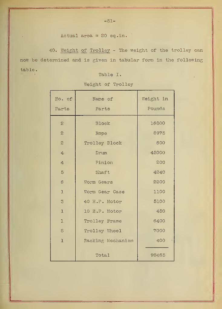
40. Weight of Trolley - The weight of the trolley can
now be determined and is given in tabular form in the following
table
.
Table I.
Weight of Trolley
No. of Name of Weight in
Parts Parts Pounds
2 Block 16800
2 Rope 8975
2 Trolley Block 600
4 Drum 45000
4 Pinion 200
5 Shaft 4240
6 Worm Gears 2200
1 Worm Gear Case 1100
3 40 H.P. Motor 5100
1 10 K.P. Motor 450
1 Trolley Frame 6400
8 Trolley Wheel 7000
1 Racking Mechanism 400 •
Total 98465


-52-
Chapter V
The Structure
41. Theory of the Structure - Knowing the weight of the
trolley and the maximum load to be lifted sufficient data is now
at hand for determining the counterweight required to balance the
structure. Fig. 35 gives a diagram of structure and the forces
acting upon it.
A general equation for the maximum horizontal reaction
H will be derived assuming that the overturning moment, when the
crane is loaded, is equal to the overturning moment with the crane
emp ty
.
Fig. 55.


-53-
Let M = overturning moment (crane loaded)
M = M " (crane unloaded)u
and taking moments about the pivot we have:
U1= Pa + K
a * Ee
- Gg
- - - (8)
Mu
= -Kf + Gg
- Ee
- - (9)
Solve for G:
G = 2Ep<
+ Pa + Ka + Kf (1Q)2 g
Substitute (10) in (9)
M = £a + -(a - f) - - ------- (11)max 2 2
Divide thru hy k we have
1Hmax n
Pa K,
f + ~ (a - f
)
(12)
Assume E = 220 tons, weight of revolving structure,
one half of v/hich or 110 tons is taken by each truss.
Load on each lower panel point
i^oo = 2o,000 lb.11
End panel points take 10000 lb.
Center of gravity of all the forces is 20 ft. to the
right of the center line of the central tower. Substituting in
equation (10) vie have for the counter-weight
2 x 220 x 20 + 150 x 112 + 50 x 112 + 50 x 28G — 1
.. .
2 x 77.5
= 210 tons
Half of this counterweight or 105 tons is taken by each
truss from which the horizontal reaction


-54-
H =120
1 75 x 112
2
= 45.75 tons
The vertical reaction
V = 210 + 150 + 50 t 220
=s 650 tons
With the horizontal and vertical reactions known the
stresses in the members due to the dead and live loads are deter-
mined according to the principles of graphic statics. Figs. 56
and 57 show the stress diagrams for the conditions of loading
which produce maximum stresses.
42. Stability of the Structure - In order to determine
whether or not the crane is safe against overturning due to the
external forces the following tables of stability give the con-
ditions of loading and the method of finding the distance out
from the center of the structure at which the center of gravity
falls. The conditions given in table VI are the most unfavorable
indicating that the base of the outer tower must be at least 60
feet square and consequently this dimension was chosen.


-55-
Tables of Stability
Table II
Superstructure only with 150 Ton Load
Tons Feet Moments+
Working Load
Trolley and Block
Revolving Jib
Counterbalance
150
50
220
210
110
110
20
77
16500
5500
4400
16200
630 26400 16200
26400 - 16200 1fl - . -= 16.2 feet from the center630
Table III
Superstructure only with no Load
Tons Feet Moments+
No Load
Trolley and Block 50 28 1400
Revolving Jib 220 20 4400
Counterbalance 210 77 16200
480 5800 16200
16200 - 5800 _ nj 7 feet480


-56-
Table IV
Crane Complete with 150 Ton Load
Tons Feet Moments+
Superstructure and Load
Tower with Roller Path
630
200
16.2
0.0
10200
830 10200
10200 —. _ _= 12.5 feet from center
830
Table V
Crane Complete with No Load
Tons Feet Moments+
Superstructure & No Load
Tower with Roller Path
480
200
21.7
0.0
10400
680 10400
10400 _ 15#3 feQt fr0m center680
Wind Forces
When the crane is unloaded the wind force produces its
greatest effect. A lateral force of 250 pounds per lineal foot
of upper and lower chord of truss will be assumed acting at the
center line of the truss, and a lateral force of 100 pounds for
each vertical lineal foot of the tower. (Cooper's Bridge Specifi-
cations )
Total wind force on truss
2(210 ft. x 250) = 105000 lb. at 160 ft. above ground


-57-
Revolving jib columns and bracing
140 ft. x 100 = 14000 lb. at 70 ft. above ground
Tower columns and bracing
140 x 100 = 14000 lb. at 62 ft. above ground
Moment of wind forces
105000 x 160 - 14000 x 70 - 14000 x 62= 140 feet
105000 - 14000 - 14000above ground
Overturning effect of wind
Table VI
Crane with no Load and Maximum Wind Force Acting
Tons Feet Moments+
Crane Complete 680 15.3 10400
Wind 66.5 140.0 9300
680 19700
=29 feet from center680
Discussion: The calculations show that with the crane
loaded with the maximum load at 110 feet radius the center of gra-
vity of the superstructure is 16.2 feet from the center of ro-
tation, and with the crane unloaded 21.7 feet. Even though the
crane is empty and there is a hurricane blowing the center of
gravity of the crane which is 29 feet from the center is never
outside the columns of the foot of the tower. Under these cir-
cumstances the foundation bolts are never stressed. It is not
probable that the most unfavorable condition as represented un-


-58-
. der Table VI will ever occur.
43. Stresses in the Rotary J ib - A graphical solution
of the stresses in the members of the jib is given in Figs. 36
and 37. The loadings for which the stresses were determined are
shown on the stress sheet. The following table gives the stresses
due to the various loadings together with the maximum and minimum
stresses
.
Table VII
Member
Trolley at outer
position With
maximum load
Trolley at inner
position without
loadMaximum
Stress
lb.»
Minimum
Stress
lb.Dead load +
live load stresses
lb.
Dead load + load
stresses due to wt
of trolley- lb.
X-l -380,000 -398,000 -398,000 -380,000
X-2 -268,000 -390,000 -390,000 -268,000
X-4 -126,000 -480,000 -480,000 -126,000
X-6 - 60,000 -556,000 -556,000 - 60,000
X-8 + 10,000 -620,000 -620,000 + 10,000
X-10 + 80,000 -674,000 -674,000 + 80,000
X-12 +134,000 -722,000 -722,000 +134,000
X-14 +180,000 -762,000 -762,000 +180,000
X-16 +222,000 -802,000 -802,000 +222,000
X-19 +226,000 -802,000 -802,000 +226,000
X-20 - 40,000 - 40,000 - 40,000 - 40,000
X-21 - 18,000 - 18,000 - 18,000 - 18,000
X-24 -320,000 -320,000 -320,000 -320,000


-59-
Table VII cont.
Member
Trolley at outer
UUoX OX Oil VI X bl±
maximum load
Trolley at inner
n o ct t + i orn w i "hVim i +
loadMaximum
Stress
lb
.
wt
.
Minimum
Stress
lb.Dead load +
live load stresses
lb .
Dead load + load
stresses due to
of trolley- lb.
X -27 -582,000 -586,000 -586,000 -582,000
X -30 -782,000 -786,000 -786,000 -782,000
X'-l -508,000 -280,000 -508,000 -280,000
X'-3 -476,000 -200,000 -476,000 -200,000
X'-5 -568,000 - 90,000 -568,000 - 90,000
X'-7 -644,000 -644,000
X'-9 -710,000 + 72,000 -710,000 + 72,000
X'-ll -764,000 +140,000 -^64,000 +140,000
X'-13 -812,000 +194,000 -812,000 +194,000
X'-15 -852,000 +240,000 -852,000 +240,000
X'-17 -890,000 +284,000 -890,000 +284,000
X'-18 -890,000 +288,000 -890,000 +288,000
X'-36 -1280,000 -334,000 -1280,000 -334,000
X'-39 -1066,000 -228,000 -1066,000 -228,000
X f -42 -828,000 -152,000 -828,000 -152,000
X'-45 -550,000 - 84,000 -550,000 - 84,000
X'-48 -234,000 - 32,000 -234,000 - 32,000
X*-51 - 16,000 - 16,000
X'-52
Y-20 + 18,000 + 16,000 +18,000 + 16,000
Y-22 +146,000 +146,000 +146,000 +146,000


-60-
Table .VII cont
.
Trolley at outer Trolley at inner
Member
position with
maximum load
position without
loadMaximum Minimum
o t-r t? s sDead load + Dead load + load
D Uro o o
live load stresses q + r>p c q o q Hnoo UI cbbcb 1J. t?
Tht
.
±u •
lb of trolley- lb.
Y-23 +148,000 +146,000 +146,000
'
+146,000
Y-25 +452,000 +454,000 +454,000 +452,000
Y-26 +452,000 +454,000 +454,000 +452,000
Y-28 +680,000 +684,000 +684,000 +680,000
Y-29 +680,000 +684,000 +684,000 +680,000
Y-31 +860,000 +860,000 +860,000 +860,000
Y-32 +860,000 +860,000 +860,000 +860,000
Y-34 +1375,000 +396,000 +1375,000 +396,000
Y-35 +1375,000 +396,000 +1375,000 +396,000
Y-37 +990,000 +274,000 +990,000 +274,000
Y-38 +990,000 +274,000 +990,000 +274,000
Y-40 +944,000 +184,000 +944,000 +184,000
Y-41 +944,000 +184,000 +944,000 +184,000
Y-43 +684,000 +112,000 +684,000 +112,000
Y-44 +684,000 +112,000 +684,000 +112,000
Y-46 +392,000 + 92,000 +392,000 + 92,000
Y-47 +392,000 + 92,000 +392,000 + 92,000
Y-49 +100,000 + 8,000 +100,000 + 8,000
Y-50 +100,000 + 8,000 +100,000 + 8,000
Y-52


Table VII cont
.
neniDer
Trolley at outer
position with
maximum load
Trolley at inner
position without
loadMaximum
D OX " o o
1 "h
U •
Minimum
O Ox t? o o
ThDead load +
live load stresses
Dead load + load
stresses due to w
a +260,000 +198,000 +260,000 +198,000
b - 76,000 - 76,000 - 76,000 - 76,000
c - 66,000 - 70,000 - 70,000 - 66,000
d - 62,000 - 64,000 - 64,000 - 62,000
e - 57,000 - 60,000 - 60,000 - 57,000
f - 53,000 - 56,000 - 56,000 - 53,000
g - 50,000 - 52,000 - 52,000 - 50,000
h - 46,000 - 48,000 - 48,000 - 46,000
i - 86,000 . - 88,000 - 88,000 - 86,000
3 -1126,000 -640,000 -1126,000 -640,000
2-3 +178,000 +136,000 +178,000 +136,000
4-5 +116,000 +116,000 +116,000 +116,000
6-7 + 98,000 +102,000 +102,000 + 98,000
8-9 + 88,000 + 90,000 + 90,000 + 88,000
10-11 + 78,000 + 80,000 + 80,000 + 78,000
12-13 + 70,000 + 72,000 + 72,000 + 70,000
14-15 + 64,000 + 66,000 + 66,000 + 64,000
16-17 +58,000 + 60,000 + 60,000 + 58,000
18-19 + 52,000 + 52,000 + 52,000 + 52,000
20-21 - 42,000 - 42,000 - 42,000 - 42,000
21-22 -194,000 -196,000 -196,000 -194,000


"Ofi-
Table VII cont.
Member
Trolley at outer
position with
maximum load
Trolley at inner
position without
loadMaximum
Stress
lb .
Minimum
Stress
lb .
Dead load +
live load stresses
lb
.
ueaa loaa +
stresses due
of trolley-
load
to w J
lb.
22-23 - 70,000 -140, 000 -140,000 - 70,000
23-24 +260,000 +<d60 , 000 +260,000 +260,000
24-25 -238,000 o a a aa a-240, 000 -240,000 -238,000
25-26
26-27 +216,000 + <d ID , UUU +216,000 +216,000
27-28 -206,000 o AQ Artn— <oUo , UUU -208,000 -206,000
28-29 AU
29-30 +196, 000 i t q/5 aaa+iyo , uuu +196,000 +196,000
30-31 -190,000 1 QQ AAA-lao, UUU -198,000 -]90,000
31-32 U
32-33 +586,000 ci n AAA-Dlo, UUU +586,000 -518,000
33-34 -584,000 i COA AAA+520, 000 -584,000 +520,000
34-35
3 R— ^fi -216,000 "i a a r\ r\ f~\-144, 000 -216,000 -144,000
36-37 +220,000 +118, 000 +220,000 +118,000
37-38
38-39 -220,000 - 20,000 -220,000 - 20,000
39-40 +226,000 + 80,000 +226,000 + 80,000
40-41
41-42 -228,000 - 64,000 -228,000 - 64,000
42-43 +240,000 + 66,000 +240,000 + 66,000


-63-
Table VII cone
.
Member
Trolley at outer
position with
maximum load
Trolley at inner
position without
loadMaximum
Stress
lb.
Minimum
Stress
lb.Dead load +
live load stresses
lb .
Dead load + load
stresses due to w
of trolley- lb
.
43-44
44-45 -240,000 - 50,000 -240,000 - 50,000
45-46 +246,000 + 52,000 +246,000 + 52,000
46-47
47-48 -260,000 - 34,000 -260,000 -34,000
48-49 +200, 000 + 34,000 +200,000 + 34,000
49-50 - 80,000 - 80,000
50-51 -148,000 - 12,000 -148,000 - 12,000
51-52 + 20,000 + 20,000 + 20,000 + 20,000
44. Tower Stresses - Fig. 38 shows a line drawing of the
outside tower and the loads acting on it. Each panel point of
the tower is subjected to the wind load acting on half a panel
length on either side of the point under consideration. The
vertical forces due to the weight of the tower were distributed
according to the best judgement of the writers since no rational
method is known. In Figs. 39-43 is given a graphical solution
of the stresses in the members of the tower due to dead and wind
loads, the wind acting in either direction. The stresses in
the members of the tower due to the different loadings, together
with the maximum and minimum stresses are shown in Table VIII.


-64-
Table VIII
Tower Stresses
Member
Dead
Load
Stress
lb.
nd Load Stress\
3 LongitudinalStress
Maximum
lb.
Minimum
lb.Wind
Right
lb
.
WindLeft
lb
.
ForceRight
lb .
ForceLeft
lb .
X-1 - 15,000 - 25,000 iv c r nnoo o , uuu - *±u
,
UUU + 10,000
X-3 - 45,000 - 2,200 +2,200 - 63,000 iT P.'*, nnn — J- JLU , uuu I- 20,200
X-5 -100,000 - 8,200 +8,200 - 89,000 fT 89. 000 -197, 000 - 2,800
X-J-2 + 15,000 + 2,200 -2,200 + 63,000 63,000 + 80, 200 -50,200
X-J-4 + 45,000 + 8,200 -8,200 + 89,000 89,000 + 142, 200 -52,200
X-S-6 +100,000 + 1 , O40 - 1 , 640 + 107, 000 107,000 +208, 640 - 8,640
X-tl - 2,000 -2,100 + 35,000 35,000 - 39, 100 +33,000
2-3 - 5,000 + 1,600 -6, 100 + 27,000 27,000 - 38, 100 +23,600
4-5 - 11,000 + 4,800 -9,300 + 21,000 21,000 - 41, 800 + 14,800
Y-6 + 2,700 -5,300 + 9,000 9,000 - 14, 300 + 11,700
1-2 - 2,900 +2, 900 - 49,000 + 49,000 - 51, 900 + 51,900
3-4 - 8,100 +8,100 - 35,000 + 35,000 - 43, 100 + 43,100
5-6 -12,000 fl2,000 - 26,000 + 26,000 - 38, 000 + 38,000


e.


w2