Embed Size (px)
Citation preview
1
DESIGN OF A 3U SATELLITE: BARQNA 786 ON CUBESAT DESIGN SPECIFICATIONS
Shoaib Mansoor, S.M. Shehzeb Abbas, Zainab Saleem
[email protected], [email protected], [email protected]
Department of Aeronautics and Astronautics, Institute of Space Technology, Islamabad,
Pakistan
Abstract—Barqna 786 is the Spacecraft Dynamics and Control project at Institute of Space Technolo-
gy, Islamabad. Pakistan. The aim of the satellite is to give a chance to the graduating students of Depart-
ment of Aeronautics & Astronautics to get familiar with the workings of satellites and therefore on the de-
sign specifications of CubeSat program, small satellites have been being designed. Barqna 786 is unique
in the aspects of having military and research benefits to Pakistan along with equipping students of insight
into the satellite designing. This paper highlights the features and capabilities of Barqna 786,
including experiments related to gathering of ocean and land data near Pakistan’s coast, GPS-based
position determination and, reaction wheel and mini-ion thrusters for attitude control.
1. Introduction
Barqna 786 is the Spacecraft Dynamics & Controls small satellite project at Institute of
Space Technology (IST) Islamabad, Pakistan. It is based on the CubeSat program started by
Stanford University and California Polytechnic State University (CalPoly)[1]
. The primary goal
of the CubeSat program is to provide students the opportunity to develop complete satellite sys-
tems and get hands on experience with space-based experiments using relatively inexpensive
satellites. The Barqna 786 is a3U satellite with a volume of 3000cm3 and maximum mass of
4.33kg. The objective of Barqna 786 is to gather data regarding sea surface temperature, ocean
winds and moisture content over land and sea using Ultra Compact Microwave Radiometer.
The constraints set forth before the design phase initiated were, it has to have benefits for Paki-
stan, must be cheaper than a Corolla Altis (PKR 2,100, 000) and has to follow the CubeSat de-
sign specifications & P-POD deployer specifications. The satellite has been designed keeping in
view the 3U capacity of a P-POD deployer. Barqna 786 will be making use of GPS and Solar
cells to determine its attitude and, reaction wheels and mini-ion thrusters are used for control-
ling the attitude and orientation of the satellite.
2
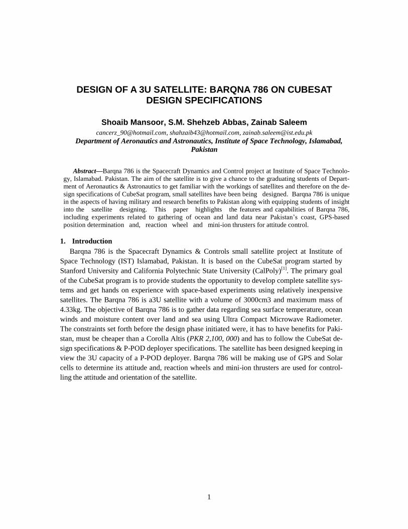
Figure 1: 3D CAD model (collapsed) of Barqna -786 (designed on Solidworks 2014)
2. DESIGN
2.1 PAYLOAD
The selected payload is Ultra Compact Microwave Radiometer which would collect data
on sea surface temperature, ocean winds and moisture content over land and sea.
The benefits to Pakistan of using such a payload are:
Benefits to navy (measurement of humidity and sea surface temperature)
Benefits to Meteorological Department of Pakistan (Ocean winds and Moisture content
over land and sea, along the coast)
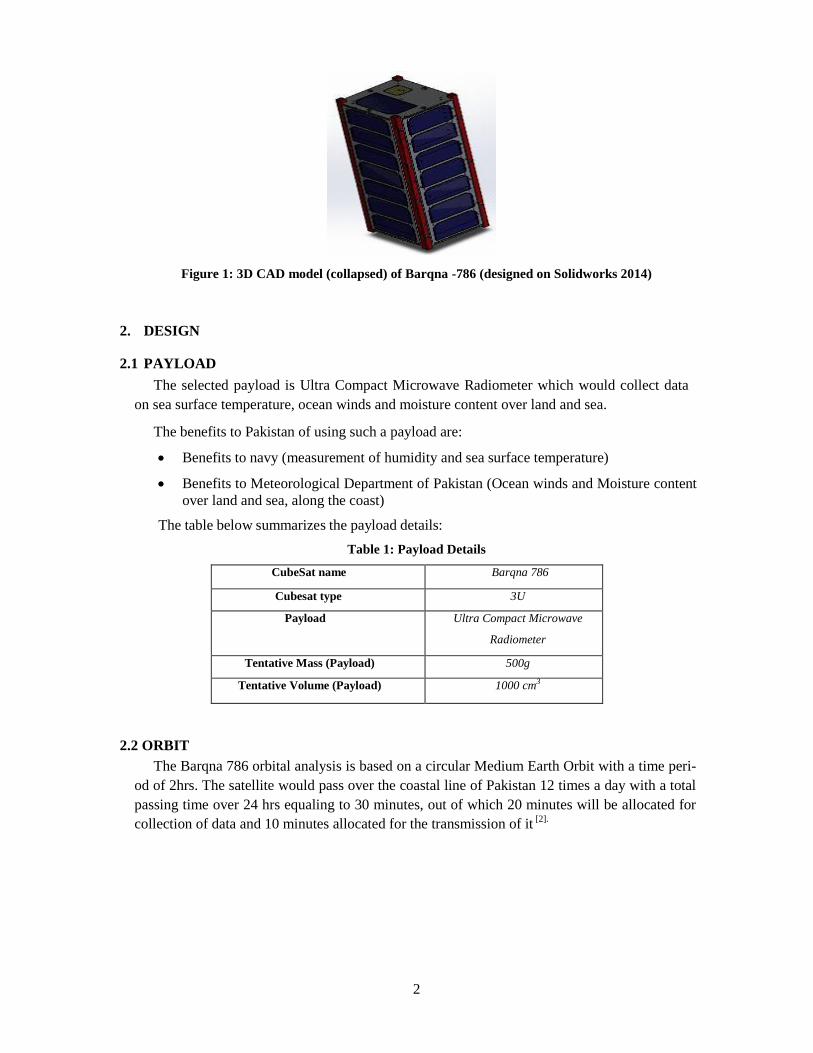
The table below summarizes the payload details:
Table 1: Payload Details
CubeSat name Barqna 786
Cubesat type 3U
Payload Ultra Compact Microwave
Radiometer
Tentative Mass (Payload) 500g
Tentative Volume (Payload) 1000 cm3
2.2 ORBIT
The Barqna 786 orbital analysis is based on a circular Medium Earth Orbit with a time peri-
od of 2hrs. The satellite would pass over the coastal line of Pakistan 12 times a day with a total
passing time over 24 hrs equaling to 30 minutes, out of which 20 minutes will be allocated for
collection of data and 10 minutes allocated for the transmission of it [2].
3
The orbit details are listed in the following table:
Table 2: Orbit Details
Time Period (hrs) 2
Radius (km) 8058.994
Altitude 1680.894
Inclination (degrees) 3.049
Data Collection (time) 02:00 – 16:00
Data Transmission (time) 18:00 – 00:00
No. Of orbits in a day 12
Frequency over Pakistan
(Hz)
1.38910-4
3. ATTITUDE AND ORBIT CONTROL
3.1 ATTITUDE DETERMINATION
Global Positioning System (GPS) is used for finding the attitude of the satellite at various in-
stants and this information is fed to the On Board Computer (OBC) for further operations. Solar
cells are present and light incident on them generates a voltage which is compared by the OBC
for right orientation of the satellite. The instant when the satellite is over the target location has a
particular intensity of Sun’s light falling on to it and it is used to correct any orientation errors.
3.2 ATTITUDE CONTROL
Reaction wheels and Mini-Ion thrusters are used for controlling the attitude of the satellite.
Reaction wheels generate less torque and are efficient in small attitude changes. Mini-ion
thrusters are used mainly for correcting the 30° phase lag due to rotation of Earth after every
2hrs. Therefore, the mini-ion thrusters have to be used to correct for the 30° phase angle, cover-
ing a ground track of 4230.972 km over the next 2hrs after the last target encounter.
4. OBC, COMMUNICATION & DATA HANDLING
Figure 2: OBC
4
OBC is purchased from clyde space, which acts as the controller of the whole cubesat sys-
tem. It integrates all the subsystems of the cubesat including communication and telemetry [3]
.
Communication and data handling is done using combination of the electrical power system, on
board computer and the payload antenna. Also GPS system sends the relative information re-
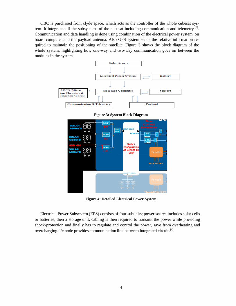
quired to maintain the positioning of the satellite. Figure 3 shows the block diagram of the
whole system, highlighting how one-way and two-way communication goes on between the
modules in the system.
Figure 3: System Block Diagram
Figure 4: Detailed Electrical Power System
Electrical Power Subsystem (EPS) consists of four subunits; power source includes solar cells
or batteries, then a storage unit, cabling is then required to transmit the power while providing
shock-protection and finally has to regulate and control the power, save from overheating and
overcharging. i2c node provides communication link between integrated circuits[4].
5
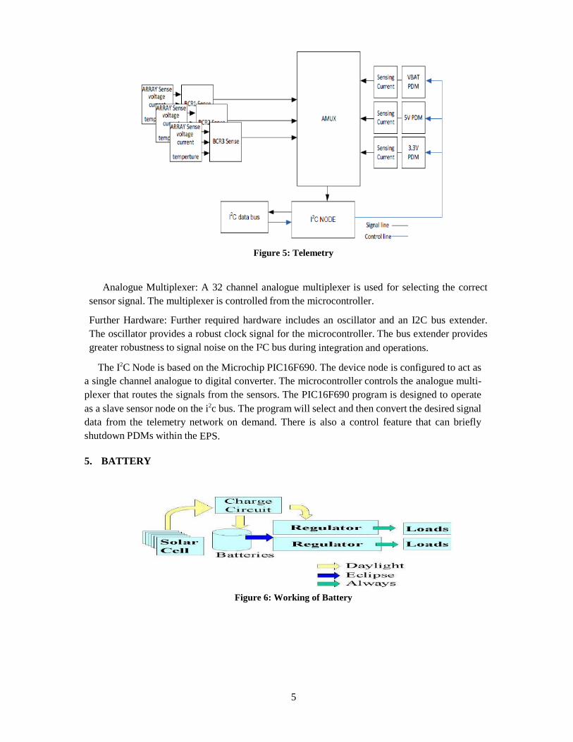
Figure 5: Telemetry
Analogue Multiplexer: A 32 channel analogue multiplexer is used for selecting the correct
sensor signal. The multiplexer is controlled from the microcontroller.
Further Hardware: Further required hardware includes an oscillator and an I2C bus extender.
The oscillator provides a robust clock signal for the microcontroller. The bus extender provides
greater robustness to signal noise on the I²C bus during integration and operations.
The I2C Node is based on the Microchip PIC16F690. The device node is configured to act as
a single channel analogue to digital converter. The microcontroller controls the analogue multi-
plexer that routes the signals from the sensors. The PIC16F690 program is designed to operate
as a slave sensor node on the i2c bus. The program will select and then convert the desired signal
data from the telemetry network on demand. There is also a control feature that can briefly
shutdown PDMs within the EPS.
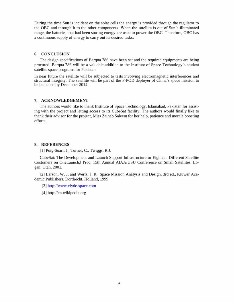
5. BATTERY
Figure 6: Working of Battery
6
During the time Sun is incident on the solar cells the energy is provided through the regulator to
the OBC and through it to the other components. When the satellite is out of Sun’s illuminated
range, the batteries that had been storing energy are used to power the OBC. Therefore, OBC has
a continuous supply of energy to carry out its desired tasks.
6. CONCLUSION
The design specifications of Barqna 786 have been set and the required equipments are being
procured. Barqna 786 will be a valuable addition to the Institute of Space Technology’s student
satellite space programs for Pakistan.
In near future the satellite will be subjected to tests involving electromagnetic interferences and structural integrity. The satellite will be part of the P-POD deployer of China’s space mission to be launched by December 2014.
7. ACKNOWLEDGEMENT
The authors would like to thank Institute of Space Technology, Islamabad, Pakistan for assist-
ing with the project and letting access to its CubeSat facility. The authors would finally like to
thank their advisor for the project, Miss Zainab Saleem for her help, patience and morale boosting
efforts.
8. REFERENCES
[1] Puig-Suari, J., Turner, C., Twiggs, R.J.
CubeSat: The Development and Launch Support Infrastructurefor Eighteen Different Satellite
Customers on OneLaunch,‖ Proc. 15th Annual AIAA/USU Conference on Small Satellites, Lo-
gan, Utah, 2001.
[2] Larson, W. J. and Wertz, J. R., Space Mission Analysis and Design, 3rd ed., Kluwer Aca-
demic Publishers, Dordrecht, Holland, 1999
[3] http://www.clyde-space.com
[4] http://en.wikipedia.org
7
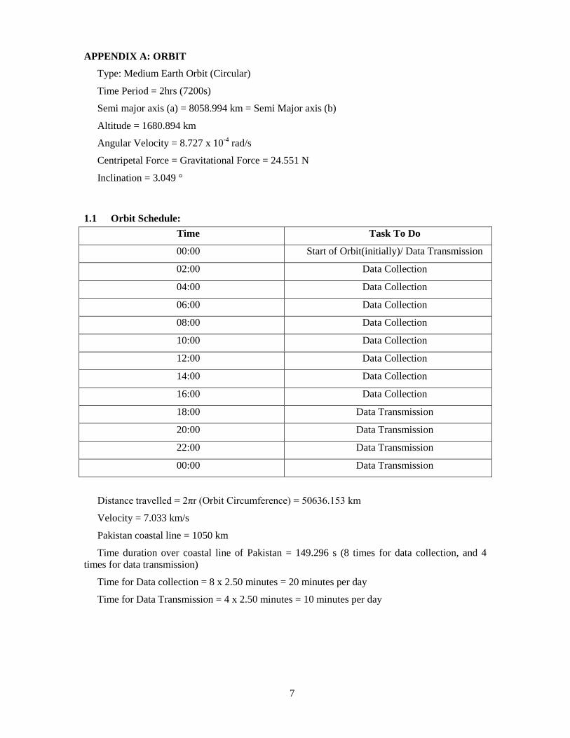
APPENDIX A: ORBIT
Type: Medium Earth Orbit (Circular)
Time Period = 2hrs (7200s)
Semi major axis (a) = 8058.994 km = Semi Major axis (b)
Altitude = 1680.894 km
Angular Velocity = 8.727 x 10⁻⁴
rad/s
Centripetal Force = Gravitational Force = 24.551 N
Inclination = 3.049 °
1.1 Orbit Schedule:
Time Task To Do
00:00 Start of Orbit(initially)/ Data Transmission
02:00 Data Collection
04:00 Data Collection
06:00 Data Collection
08:00 Data Collection
10:00 Data Collection
12:00 Data Collection
14:00 Data Collection
16:00 Data Collection
18:00 Data Transmission
20:00 Data Transmission
22:00 Data Transmission
00:00 Data Transmission
Distance travelled = 2πr (Orbit Circumference) = 50636.153 km
Velocity = 7.033 km/s
Pakistan coastal line = 1050 km
Time duration over coastal line of Pakistan = 149.296 s (8 times for data collection, and 4
times for data transmission)
Time for Data collection = 8 x 2.50 minutes = 20 minutes per day
Time for Data Transmission = 4 x 2.50 minutes = 10 minutes per day
8
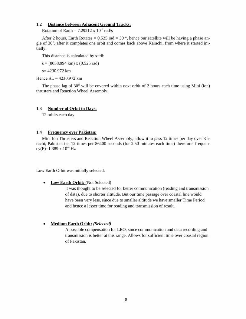
1.2 Distance between Adjacent Ground Tracks:
Rotation of Earth = 7.29212 x 10⁻⁵
rad/s
After 2 hours, Earth Rotates = 0.525 rad = 30 °, hence our satellite will be having a phase an-
gle of 30°, after it completes one orbit and comes back above Karachi, from where it started ini-
tially.
This distance is calculated by s=rθ:
s = (8058.994 km) x (0.525 rad)
s= 4230.972 km
Hence ∆L = 4230.972 km
The phase lag of 30° will be covered within next orbit of 2 hours each time using Mini (ion)
thrusters and Reaction Wheel Assembly.
1.3 Number of Orbit in Days:
12 orbits each day
1.4 Frequency over Pakistan:
Mini Ion Thrusters and Reaction Wheel Assembly, allow it to pass 12 times per day over Ka-
rachi, Pakistan i.e. 12 times per 86400 seconds (for 2.50 minutes each time) therefore: frequen-
cy(F)=1.389 x 10⁻⁴
Hz
Low Earth Orbit was initially selected:
Low Earth Orbit: (Not Selected)
It was thought to be selected for better communication (reading and transmission
of data), due to shorter altitude. But our time passage over coastal line would
have been very less, since due to smaller altitude we have smaller Time Period
and hence a lesser time for reading and transmission of result.
Medium Earth Orbit: (Selected)
A possible compensation for LEO, since communication and data recording and
transmission is better at this range. Allows for sufficient time over coastal region
of Pakistan.
9
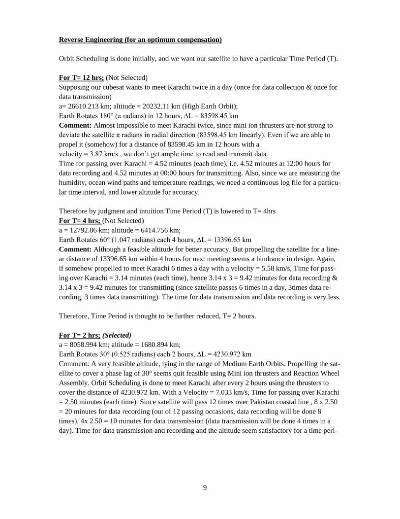
Reverse Engineering (for an optimum compensation)
Orbit Scheduling is done initially, and we want our satellite to have a particular Time Period (T).
For T= 12 hrs; (Not Selected)
Supposing our cubesat wants to meet Karachi twice in a day (once for data collection & once for
data transmission)
a= 26610.213 km; altitude = 20232.11 km (High Earth Orbit);
Earth Rotates 180° (π radians) in 12 hours, ∆L = 83598.45 km
Comment: Almost Impossible to meet Karachi twice, since mini ion thrusters are not strong to
deviate the satellite π radians in radial direction (83598.45 km linearly). Even if we are able to
propel it (somehow) for a distance of 83598.45 km in 12 hours with a
velocity = 3.87 km/s , we don’t get ample time to read and transmit data.
Time for passing over Karachi = 4.52 minutes (each time), i.e. 4.52 minutes at 12:00 hours for
data recording and 4.52 minutes at 00:00 hours for transmitting. Also, since we are measuring the
humidity, ocean wind paths and temperature readings, we need a continuous log file for a particu-
lar time interval, and lower altitude for accuracy.
Therefore by judgment and intuition Time Period (T) is lowered to T= 4hrs
For T= 4 hrs; (Not Selected)
a = 12792.86 km; altitude = 6414.756 km;
Earth Rotates 60° (1.047 radians) each 4 hours, ∆L = 13396.65 km
Comment: Although a feasible altitude for better accuracy. But propelling the satellite for a line-
ar distance of 13396.65 km within 4 hours for next meeting seems a hindrance in design. Again,
if somehow propelled to meet Karachi 6 times a day with a velocity = 5.58 km/s, Time for pass-
ing over Karachi = 3.14 minutes (each time), hence 3.14 x 3 = 9.42 minutes for data recording &
3.14 x 3 = 9.42 minutes for transmitting (since satellite passes 6 times in a day, 3times data re-
cording, 3 times data transmitting). The time for data transmission and data recording is very less.
Therefore, Time Period is thought to be further reduced, T= 2 hours.
For T= 2 hrs; (Selected)
a = 8058.994 km; altitude = 1680.894 km;
Earth Rotates 30° (0.525 radians) each 2 hours, ∆L = 4230.972 km
Comment: A very feasible altitude, lying in the range of Medium Earth Orbits. Propelling the sat-
ellite to cover a phase lag of 30° seems quit feasible using Mini ion thrusters and Reaction Wheel
Assembly. Orbit Scheduling is done to meet Karachi after every 2 hours using the thrusters to
cover the distance of 4230.972 km. With a Velocity = 7.033 km/s, Time for passing over Karachi
= 2.50 minutes (each time). Since satellite will pass 12 times over Pakistan coastal line , 8 x 2.50
= 20 minutes for data recording (out of 12 passing occasions, data recording will be done 8
times), 4x 2.50 = 10 minutes for data transmission (data transmission will be done 4 times in a
day). Time for data transmission and recording and the altitude seem satisfactory for a time peri-
10
od of 2 hours, also with continuous data recording payload performance will be much more effi-
cient.
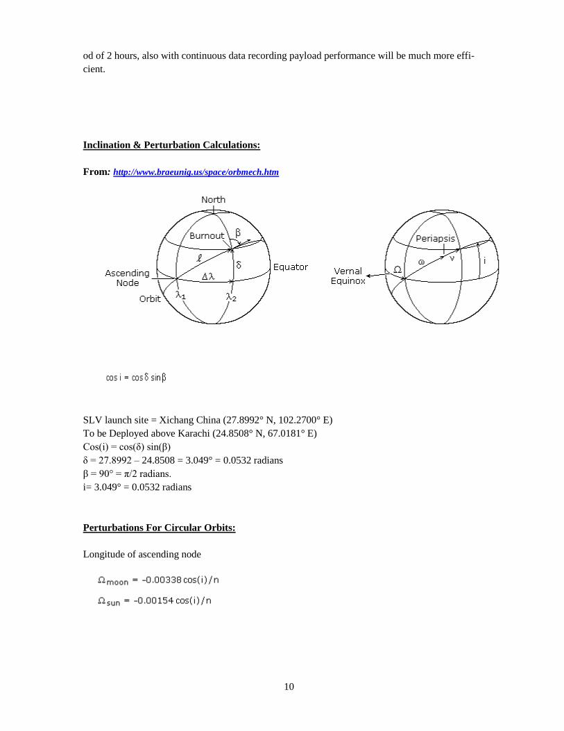
Inclination & Perturbation Calculations:
From: http://www.braeunig.us/space/orbmech.htm
SLV launch site = Xichang China (27.8992° N, 102.2700° E)
To be Deployed above Karachi (24.8508° N, 67.0181° E)
Cos(i) = cos(δ) sin(β)
δ = 27.8992 – 24.8508 = 3.049° = 0.0532 radians
β = 90° = π/2 radians.
i= 3.049° = 0.0532 radians
Perturbations For Circular Orbits:
Longitude of ascending node
11
ῼmoon = -2.813 x 10⁻⁴
deg/day
ῼsun = -1.282 x 10⁻⁴
deg/day
Argument of perigee/ apogee/ semi major axis :
ωmoon = 5.613 x 10⁻⁴
deg/day
ωsun = 2.558 x 10⁻⁴
deg/day
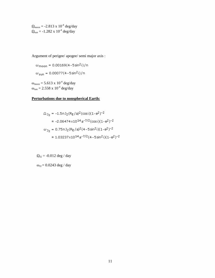
Perturbations due to nonspherical Earth:
ῼJ2 = -0.012 deg / day
ωJ2 = 0.0243 deg / day
12
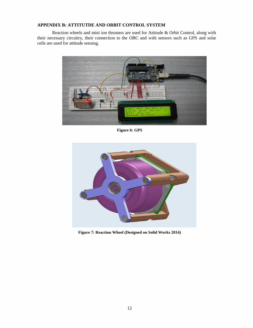
APPENDIX B: ATTITUTDE AND ORBIT CONTROL SYSTEM
Reaction wheels and mini ion thrusters are used for Attitude & Orbit Control, along with
their necessary circuitry, their connection to the OBC and with sensors such as GPS and solar
cells are used for attitude sensing.
Figure 6: GPS
Figure 7: Reaction Wheel (Designed on Solid Works 2014)
13
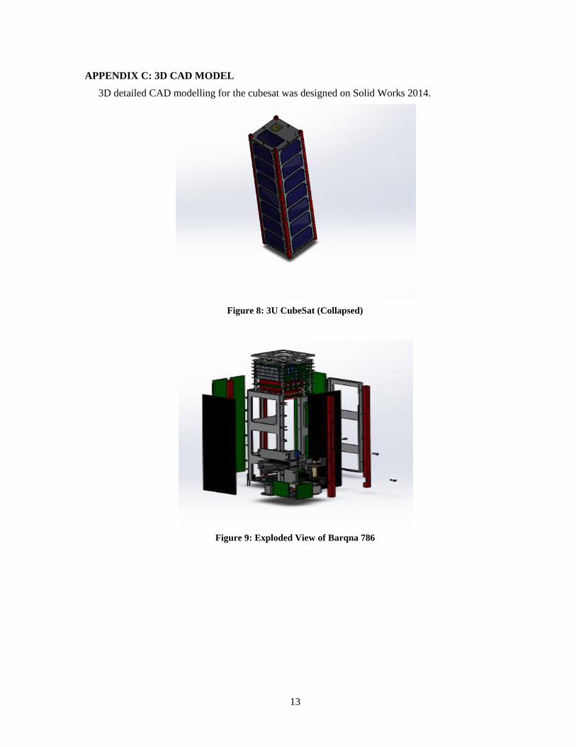
APPENDIX C: 3D CAD MODEL
3D detailed CAD modelling for the cubesat was designed on Solid Works 2014.
Figure 8: 3U CubeSat (Collapsed)
Figure 9: Exploded View of Barqna 786
14
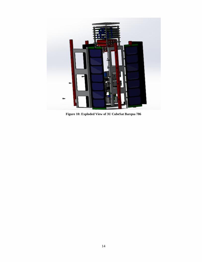
Figure 10: Exploded View of 3U CubeSat Barqna 786