Embed Size (px)
Citation preview

Design of a 50 m Pulsar Radio Telescope
Dehua Yanga*, Shuangshuo Xuea, Daxing Wanga, Wenzhi Lua, Jingquan Chengb
aNational Astronomical Observatories / NIAOT, CAS, P. R. China
bNational Radio Astronomy Observatory, Tucson, AZ, USA
ABSTRACTA radio telescope is to be built at National Astronomical Observatory of China, which is designed to receive signal frompulsars for timing and relevant usage. The telescope will have an aperture of 50 m in diameter working at multi-wavebands of which the shortest wavelength is down to 13 cm. A fully steerable exposed scheme of the telescope withinissued specification is studied. The design is essentially wheel and track style with 6 rollers grouped in three couplesrunning on a track of 35 m in diameter. The main paraboloidal reflector is a mesh spanned with cramped stainless steelwire installed on a special "bowl-like" backup truss structure supported by 6 points on the bottom. The elevation motionis served by a couple of big spoke and brace welded gearwheels with “buoyant” unloading system for eliminatingdeflections due to deadweight and thermal effect. Besides the design of the main reflector back-up structure, this paperpresents the special alidade layout, driving system, structural and wind hazard analyses, and includes servo controlsystem before drawing a general conclusion.
Keywords: Pulsar radio telescope, Wheel-on-track style, Backup structure, Structure analyses, Servo control
1. INTRODUCTIONRadio signal from a pulsar appears with extremely stable periodicity, some pulsars with period of milli-seconds caneven be used for timing and for crosschecking with atomic clocks. As the counterpart of “atomic clock”, such “clock” iscalled “pulsar clock”, which is essentially a radio telescope working at some special wavelength. There already existsuch clocks also called pulsar radio telescopes1.
Three years ago, a pulsar radio telescope with an aperture of 50 m in diameter was proposed by Chinese AcademicianShouguan Wang at NAOC. Agreeing with scientific arguments2, the shortest working band of the telescope is settled asdown to 13 cm wavelength, so, in any working cases, the normal deflection (RMS) of the dish surface can not exceed~1/20 of operational wavelength, namely, no greater than 7 mm at shortest working wavelength. And the pointing andtracking accuracies are both better than 1 arcminute. It uses both prime and Cassegrain optical systems with f/0.4. As anbig exposed radio telescope, it is very necessary and important to investigate its performance under different workingconditions, normally, dynamical requirements should cover that the separate dish part should reach 2-3 Hz as lowesteigenfrequency while the whole telescope system must be as stiff as enough to reach 1.5 Hz at least3.
In 2001, detailed design goals and specifications of the pulsar telescope are issued3, and since then, by investigating intoand by comparing with existing radio telescope projects, the authors have drafted two design schemes of thetelescope4,5. This paper describes the second version of the scheme. As seen in Fig. 1 and Fig. 2, it has essentially turnedto be a 50 m diameter wire-meshed paraboloidal reflector on a wheel-track style elevation-azimuth mounting whichserves tracking and pointing. The telescope system includes, the special “bowl-like” reflector backup structure, thespecial three-point supporting and driving alidade, the couple of big spoke elevation gears with buoyant unloadingtechnique, and the corresponding telescope control system. Designed and emulated with computer programs, the wholesystem meets technical specification very well and exhibits good performance in weight and cost by balancing bothstructural and electronic efforts in the telescope design.
2. THE REFLECTOR STRUCTURE DESIGNAt the beginning of investigation into the reflector backup structure design, the Effelsberg 100 m dish was naturally thefirst to be referred6. As one of the world biggest15 fully steerable telescope even able to work down to 3.5 mm
* Correspondence: Email: [email protected]; Telephone: +86-25-5482-210; Fax: +86-25-5405562; http://www.nairc.ac.cn;Nanjing Institute of Astronomical Optics & Technology (NIAOT), Bancang Str. 188 210042 Nanjing P. R. China
Millimeter and Submillimeter Detectors for Astronomy, Thomas G. Phillips, Jonas Zmuidzinas,Editors, Proceedings of SPIE Vol. 4855 (2003) © 2003 SPIE · 0277-786X/03/$15.00
528
Downloaded from SPIE Digital Library on 22 Aug 2010 to 159.226.100.201. Terms of Use: http://spiedl.org/terms

�
Fig. 1: The 50-m pulsar radio telescope
Fig. 2: Overall dimensions of the 50-m pulsar radio telescope
Proc. of SPIE Vol. 4855 529
Downloaded from SPIE Digital Library on 22 Aug 2010 to 159.226.100.201. Terms of Use: http://spiedl.org/terms

Wavelength, the Effelsberg dish has been successful and famous for its special homogeneous design. Our to-be-designed dish is, however, half size of the Effeslsberg dish and moreover working at longer wavelength, it possible toseek an easier way to achieve its technical specification. Afterwards, we looked into the Westerbork dish7, which is anelegantly simple design, and enlightens us with some new ideas.
Fig. 3: Section of the bowl-like backup structure with elevation gearwheels shown (left)
Fig. 4: Layout of backup structure
As seen in Fig. 3 and Fig. 4, the profile of the backup structure looks like a bowl. It comprises four groups ofcircumferential rings classified outwards as the inner ring, the support ring, the secondary outer ring and the outer ring,of which, the inner ring and the outer ring are single layer/planar trusses, while the secondary outer ring is a double-layered truss and the support ring a special triangularly cross-sectioned circular truss with diameter of 25 m, underwhich there is an additional auxiliary conic girder ring forming the “bottom of bowl”. Note that, elevation axis and twobig gearwheels are to be connected only to the “bottom of the bowl” but separate from the backup structure, namely, thebackup structure is settled on a six-point support system (refer to Fig. 5). The truss height is strictly decided to minimizethe distance between the elevation axis and the vertex of the paraboloidal reflecting surface so as to minimizecounterweight. There are totally 16 full length and 48 shorter radial ribs (Fig. 4). The layout of other framing membersin the reflector structure is determined according to the principle of geometric stability and direct force transfer. So,comparatively, the upper and lower components of the ribs are thicker than the interior braces, also, relatively,
530 Proc. of SPIE Vol. 4855
Downloaded from SPIE Digital Library on 22 Aug 2010 to 159.226.100.201. Terms of Use: http://spiedl.org/terms
components turns thinner outwards over the backup structure. All components are to be industrial formed steel pipes tolower cost and wind load9,12.
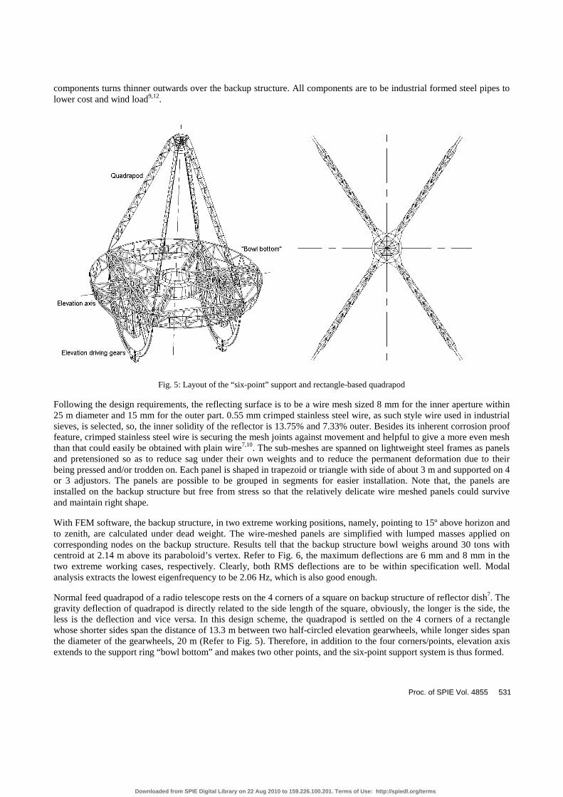
Fig. 5: Layout of the “six-point” support and rectangle-based quadrapod
Following the design requirements, the reflecting surface is to be a wire mesh sized 8 mm for the inner aperture within25 m diameter and 15 mm for the outer part. 0.55 mm crimped stainless steel wire, as such style wire used in industrialsieves, is selected, so, the inner solidity of the reflector is 13.75% and 7.33% outer. Besides its inherent corrosion prooffeature, crimped stainless steel wire is securing the mesh joints against movement and helpful to give a more even meshthan that could easily be obtained with plain wire7,10. The sub-meshes are spanned on lightweight steel frames as panelsand pretensioned so as to reduce sag under their own weights and to reduce the permanent deformation due to theirbeing pressed and/or trodden on. Each panel is shaped in trapezoid or triangle with side of about 3 m and supported on 4or 3 adjustors. The panels are possible to be grouped in segments for easier installation. Note that, the panels areinstalled on the backup structure but free from stress so that the relatively delicate wire meshed panels could surviveand maintain right shape.
With FEM software, the backup structure, in two extreme working positions, namely, pointing to 15º above horizon andto zenith, are calculated under dead weight. The wire-meshed panels are simplified with lumped masses applied oncorresponding nodes on the backup structure. Results tell that the backup structure bowl weighs around 30 tons withcentroid at 2.14 m above its paraboloid’s vertex. Refer to Fig. 6, the maximum deflections are 6 mm and 8 mm in thetwo extreme working cases, respectively. Clearly, both RMS deflections are to be within specification well. Modalanalysis extracts the lowest eigenfrequency to be 2.06 Hz, which is also good enough.
Normal feed quadrapod of a radio telescope rests on the 4 corners of a square on backup structure of reflector dish7. Thegravity deflection of quadrapod is directly related to the side length of the square, obviously, the longer is the side, theless is the deflection and vice versa. In this design scheme, the quadrapod is settled on the 4 corners of a rectanglewhose shorter sides span the distance of 13.3 m between two half-circled elevation gearwheels, while longer sides spanthe diameter of the gearwheels, 20 m (Refer to Fig. 5). Therefore, in addition to the four corners/points, elevation axisextends to the support ring “bowl bottom” and makes two other points, and the six-point support system is thus formed.
Proc. of SPIE Vol. 4855 531
Downloaded from SPIE Digital Library on 22 Aug 2010 to 159.226.100.201. Terms of Use: http://spiedl.org/terms

Each feed quadrapod leg is a triangle-sectioned truss whose lower end degenerates into a long parallel triangular forkgoing through the reflecting panel mesh and backup structure and at last converges at one of the four rectangle’scorners. In view of minimizing blockage and maximizing stiffness, the feed leg truss is cross-sectioned as isoscelestriangle with shorter side circumferentially laid (refer to Fig. 5).
Fig. 6: Layout of the “six-point” support and rectangle-based quadrapod
3. THE DRIVING SYSTEMSThe driving system of the 50 m pulsar telescope intrinsically consists of two sub-systems: the elevation driving systemand the azimuth driving system.
3.1 Elevation driving system
Actually, as mentioned before, the elevation driving system is double gear driving sets. As detailed in Fig. 7, the bodyof the big gearwheel is a halved circle and fabricated of spokes and braces, the gear effective teeth block spans 100º,covering whole elevation motion range. Technologically, the teeth block is essentially made up with several racksconnected end by end. And the counterweight ballasts are installed on the both big gearwheels’ flanges. Each of the twobig half-circled gears is connected to the bottom of the backup structure bowl with two ends of its 20 m length diameter.And each big gear meshes with two pinions of 250 mm in diameter to eliminate backlash. The small pinion carriage is
532 Proc. of SPIE Vol. 4855
Downloaded from SPIE Digital Library on 22 Aug 2010 to 159.226.100.201. Terms of Use: http://spiedl.org/terms
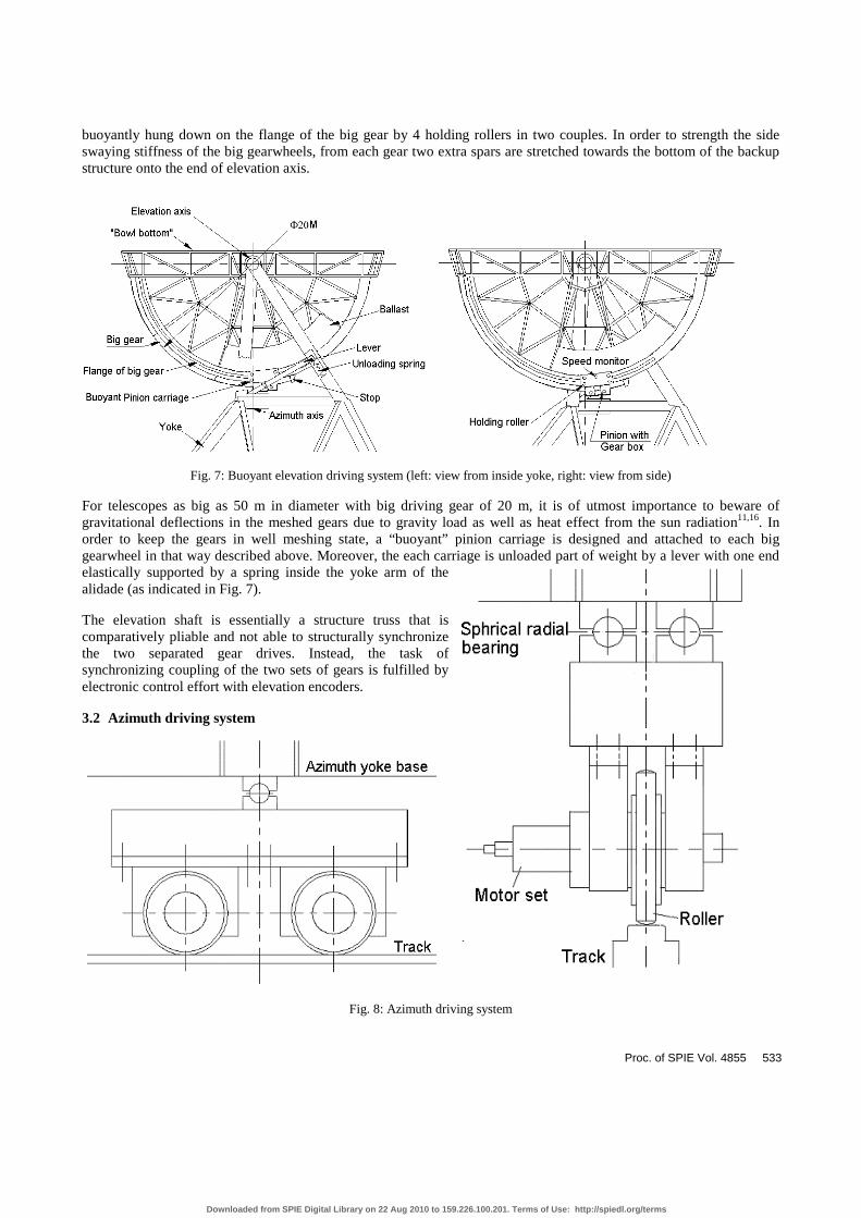
buoyantly hung down on the flange of the big gear by 4 holding rollers in two couples. In order to strength the sideswaying stiffness of the big gearwheels, from each gear two extra spars are stretched towards the bottom of the backupstructure onto the end of elevation axis.
Fig. 7: Buoyant elevation driving system (left: view from inside yoke, right: view from side)
For telescopes as big as 50 m in diameter with big driving gear of 20 m, it is of utmost importance to beware ofgravitational deflections in the meshed gears due to gravity load as well as heat effect from the sun radiation11,16. Inorder to keep the gears in well meshing state, a “buoyant” pinion carriage is designed and attached to each biggearwheel in that way described above. Moreover, the each carriage is unloaded part of weight by a lever with one endelastically supported by a spring inside the yoke arm of thealidade (as indicated in Fig. 7).
The elevation shaft is essentially a structure truss that iscomparatively pliable and not able to structurally synchronizethe two separated gear drives. Instead, the task ofsynchronizing coupling of the two sets of gears is fulfilled byelectronic control effort with elevation encoders.
3.2 Azimuth driving system
Fig. 8: Azimuth driving system
Proc. of SPIE Vol. 4855 533
Downloaded from SPIE Digital Library on 22 Aug 2010 to 159.226.100.201. Terms of Use: http://spiedl.org/terms
The Azimuth driving unit is actually friction driving system. It is a combination of three couples of rollers orbiting on atrack of 35 m in diameter (refer to Fig. 1 and Fig. 8). The three couples are installed on the three corners of theequilateral-triangle-based alidade. Each pair of rollers is able to self position via a couple of spherical plain radialbearing hinges. Also, the synchronized collaboration of the three azimuth driving couples is secured by servo controlsystem.
The track itself is made of a group of segments of steel plate connecting by 45º seams with ~2 mm width left. Thenormal runout of the track is restricted within 0.1 mm.
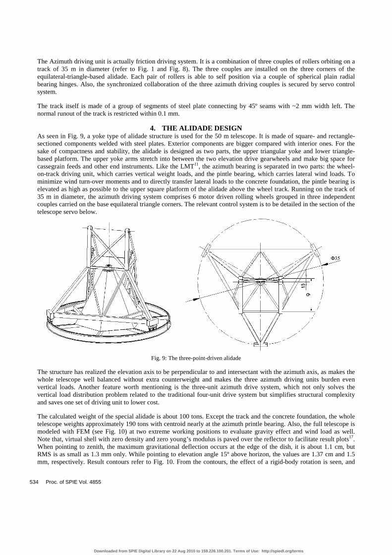
4. THE ALIDADE DESIGNAs seen in Fig. 9, a yoke type of alidade structure is used for the 50 m telescope. It is made of square- and rectangle-sectioned components welded with steel plates. Exterior components are bigger compared with interior ones. For thesake of compactness and stability, the alidade is designed as two parts, the upper triangular yoke and lower triangle-based platform. The upper yoke arms stretch into between the two elevation drive gearwheels and make big space forcassegrain feeds and other end instruments. Like the LMT11, the azimuth bearing is separated in two parts: the wheel-on-track driving unit, which carries vertical weight loads, and the pintle bearing, which carries lateral wind loads. Tominimize wind turn-over moments and to directly transfer lateral loads to the concrete foundation, the pintle bearing iselevated as high as possible to the upper square platform of the alidade above the wheel track. Running on the track of35 m in diameter, the azimuth driving system comprises 6 motor driven rolling wheels grouped in three independentcouples carried on the base equilateral triangle corners. The relevant control system is to be detailed in the section of thetelescope servo below.
Fig. 9: The three-point-driven alidade
The structure has realized the elevation axis to be perpendicular to and intersectant with the azimuth axis, as makes thewhole telescope well balanced without extra counterweight and makes the three azimuth driving units burden evenvertical loads. Another feature worth mentioning is the three-unit azimuth drive system, which not only solves thevertical load distribution problem related to the traditional four-unit drive system but simplifies structural complexityand saves one set of driving unit to lower cost.
The calculated weight of the special alidade is about 100 tons. Except the track and the concrete foundation, the wholetelescope weights approximately 190 tons with centroid nearly at the azimuth printle bearing. Also, the full telescope ismodeled with FEM (see Fig. 10) at two extreme working positions to evaluate gravity effect and wind load as well.Note that, virtual shell with zero density and zero young’s modulus is paved over the reflector to facilitate result plots17.When pointing to zenith, the maximum gravitational deflection occurs at the edge of the dish, it is about 1.1 cm, butRMS is as small as 1.3 mm only. While pointing to elevation angle 15º above horizon, the values are 1.37 cm and 1.5mm, respectively. Result contours refer to Fig. 10. From the contours, the effect of a rigid-body rotation is seen, and
534 Proc. of SPIE Vol. 4855
Downloaded from SPIE Digital Library on 22 Aug 2010 to 159.226.100.201. Terms of Use: http://spiedl.org/terms

thanks to the predictable linear elastic telescope system, it is possible to be partly compensated by elevation motion.Cooperatively, the sub-reflector will also actively move to the focus of the best-fitted paraboloid12,13,14.
Fig. 10: The FEM of the 50 m telescope (pointing to 15º) and results under gravity
Proc. of SPIE Vol. 4855 535
Downloaded from SPIE Digital Library on 22 Aug 2010 to 159.226.100.201. Terms of Use: http://spiedl.org/terms

The required operational wind2 speed is specified as 17 m/s and survival wind2 speed 40 m/s. By assuming equivalentwind loads are evenly distributed onto the nodes over the reflector surface, four cases of load are calculated at the twoextreme working positions: wind comes from the front of the reflector dish and wind comes from the side of the dish,respectively. Refer to Fig. 11, the FEM and a result contour is shown. Table 1 contains the final results from botheffects of gravity and wind, which declare that the telescope is able to work well with full aperture against the requiredoperational wind speed, i.e., 17 m/s.
Fig. 11: The FEM under wind load including gravity (pointing to zenith) and result contour
Table 1: Results of wind load calculation
Displacement on reflector (mm)Wind @ 17 m/s
Absolute Max. Average RMS������ 13.4 6.7 1.92
Zenith��� 11.6 6.4 1.73������ 21.6 11.6 2.55
15º��� 14.2 8.8 1.52
Fig. 12: The FEM under wind load including gravity (pointing to zenith) and result contour
536 Proc. of SPIE Vol. 4855
Downloaded from SPIE Digital Library on 22 Aug 2010 to 159.226.100.201. Terms of Use: http://spiedl.org/terms

An important calculation dictates that, to survive in the wind of 40 m/s, the reflector dish has to be elevated towardszenith to minimizing wind load and consequent wind turn-over moment. The introduced reactive forces at the threeazimuth driving pairs are 81 tons, 81 tons and 28.5 tons, respectively. All are positive and reasonable so the telescopecan not be turned over by the wind.
Additionally, the first eigenfrequecy is high enough up to 2.28 Hz with corresponding mode shape of the elevationgearwheels’ swaying motion. See Fig. 12, the next modal shape is rotation about azimuth axis.
5. THE SERVO AND CONTROL SYSTEMTo achieve an overall good telescope with high cost performance, nowadays, the efforts of both structure system andservo control system are cooperatively contributing to seek a better design8,11. As detailed in forgoing paragraphs, theelevation motion is served by double gear pair drive, while the azimuth served by friction drive with three pairs ofrollers, and the servo system is responsible for controlling the both.
Traditionally, if driven by elevation shaft, the shaft must be strong and stiff enough to transfer driving torque. For a 50m telescope like this design with elevation span as wide as 13.3 m, it is hard to fabricate and ensure an ideal sufficientlystiff elevation shaft. Generally, the torsion angle in a shaft under torque is given by the formula below:
∑=
=n
i p
i radI
lM
G 1
1ϕ . (1)
where, M is driving torque, L is the effective length of axis under the torque, G is the shear modulus of the shaft
material, and pI is polar moment of inertia of the shaft.
By rough computation, if the total elevation driving torque is needed to be 6.4e5 Nm, and if the torsion angle isconfined within 0.25º, the diameter of the shaft must be up to ~ 500 mm, which is technically impractical.
The servo control system of the telescope is charted in Fig. 13, which is inherently a three-loop position control system.Actually, current/moment control is also included to ensure the telescope to work under wind load (not shown in theFigure).
Thus, based on the above arguments, essentially a common double-DC motor control system with backlash eliminatingtechnique is employed for elevation drive. The synchronization within tolerance of 0.25º (=15�) between the two pairsof gear sets/motors can be realized by assuming one is master and the other slave. And a pair of encoders of 14-bit(resolution 1.3�) installed with each of the two big gearwheels. The difference between both encoders’ output is to beservo signal for motor’s speed control. The absolute positions of both sets are to be measured by absolute angulardisplacement sensors and compensated with DSP technique. While the final elevation angular position is monitored bya combination of resolver and inductosyn of 20-bit output, i.e., resolution up to 1�
As to azimuth drive, it is a traditional friction wheel-on-track system driven by six motors working simultaneously inthree pairs. The servo control system has to ensure the six wheels to run at equal linear speed and distribute the equalazimuth motion load onto them. So, a multi-motor synchro-control system is introduced. It features in the followingaspects:
1. Speed equalizer is used to get stable and uniform base speed for all the DC motors because of their intrinsic outputspeed differences;
2. Usually, angular misalignment is used as control parameter in synchro-control system. In order to synchronize the 6rollers to run at even speed within permitted fluctuation, the linear speeds of the rollers are measured by incrementoptical encoders and compensated after being analyzed also by DSP technique.
Proc. of SPIE Vol. 4855 537
Downloaded from SPIE Digital Library on 22 Aug 2010 to 159.226.100.201. Terms of Use: http://spiedl.org/terms

6. CONCLUSIONThe design scheme of the 50 m pulsar telescope features in a few particular aspects described in above sections. Thespecial lightweight “bowl-like” backup structure supported by six points at bottom exhibits good performance to meetissued specifications well with full aperture in all operational conditions. The reflector panels using crimped stainlesssteel wire is good for minimizing weight and wind loads. Structural deflection due to dead gravity and thermal effect isconsiderable for big telescopes, in this design, it is solved by the elevation gear driving pairs with unloaded buoyantpinion carriages. The quadrapod is laid out with rectangle-based support to minimize gravity deflection. Special alidadelayout is introduced with three azimuth driving units, which lowers cost and complexity, together with effortcontributed by electronic servo control system, the whole telescope achieves very good price performance ratio withlight weight and high stiffness.
Fig. 13: The elevation motion servo system of 50 m telescope
538 Proc. of SPIE Vol. 4855
Downloaded from SPIE Digital Library on 22 Aug 2010 to 159.226.100.201. Terms of Use: http://spiedl.org/terms

7. ACKNOWLEDGEMENTThe authors are grateful to NIAOT and NAOC for supporting them to work on the design, and thank the peers atShanghai Astronomical Observatory for their cooperation during design investigation. Also many thanks to Miss QiuhuiHe, graduate student at NIAOT, for her kind help.
8. REFERENCES1. Guangren Ni, Tinggao Yang, Dangli Zhao, “Timing and develop of millisecond pulsars”, Shaanxi Astronomical
Obseravtory, CAS.2. NAOC, “Letter on Inviting bidding on Conceptual Design of the 50 m Aperture Radio Telescope”�NAOC, CAS,
Jul. 2001.3. Cheng Jingquan, “Steerable Parabolic Antenna Design”, Ph.D. thesis, 1984.4. Dehua Yang et al, “Design Scheme of the 50 m Aperture Pulsar Radio Telescope”, Version 1, Jun. 2001.5. Dehua Yang et al, “Design Scheme of the 50 m Aperture Pulsar Radio Telescope”, Version 2, Oct. 2001.6. Von Dipl.-Ing. H. Altmann, Rheinhauson, “Die Stahlkonstruktion des 100-m-Radiotelescopes in Effelsberg”, Der
Stahlbau, Jg. 41, H. 11, S. 321-331, H. 12, S. 360-367, 1972.7. G. Hooghoudt, “The Synthesis Radio Telescope at Westerbork, Holland”, Leiden, Holand8. D. E. N. Davies, “Proposals for electronic Compensation of Surface Profile Errors in Large Reflectors”,
Department of Electronic & Electricity Engineering, Univ. of Birmingham.9. P. Blacksmith & A. C. Schell, “A Comparison of three Antenna Techniques in Terms of Cost versus Performance”,
Lab. Air force Cambridge Research Lab, Massachusetts.10. C. R. Blackwell Freeman Fox & Partners, “The Reflector Dishes of the 210 ft. Diameter Radio Telescope At Parks,
Australia & The 150 ft. Diameter Radio Telescope At Lake Traverse, Ontario”.11. Hans J. Kaercher & Jacob W. M. Baars, “The Design of the Large Millimeter Telescope/Gran Telescopio
Milimetrico (LMT/GTM)”, Proc. Of SPIE, Vol. 4015, pp. 155-168, April 2000.12. “Computer-aided Design of a Large Steerable Antenna Structure”, Structures Technology for Large Radio and
Radar Telescope System, pp. 247-271.13. John Ruze, “Small Displacement in Parabolic Reflectors”, 1969, MIT Lincoln Laboratory.14. M. Isher, “Obtaining Beam-Pointing Accuracy with Cassegrain Antennas Anthony”, 1967.15. P. R. Jewell, “The Green Bank Telecope”, Proc. Of SPIE, Vol. 4015, pp. 136-147, April 2000.16. K. Schneider and W. Schonbach MAN Gustarsburg Works, “Design Study for 80-Meter Radio Telescope”.17. Dehua Yang, “Structural Analysis of a 50-m Pulsar Radio Telescope”, Proc. Of ANSYS 2002 Users Conference
and Exhibition, April 22-24, 2002.
Proc. of SPIE Vol. 4855 539
Downloaded from SPIE Digital Library on 22 Aug 2010 to 159.226.100.201. Terms of Use: http://spiedl.org/terms