Embed Size (px)
Citation preview
Design of a Cascade Planar Transformer for Electrostatic Precipitator
Use
YAN AN WANG1, MIN HU
1,2, DENG MING XIAO
1, YI MIN JIANG
2
1School of Electronic, Information and Electrical Engineering, Shanghai Jiaotong University,
Minhang District, Shanghai 200240, CHINA, [email protected] 2Shanghai Electric Power Company, Pudongxinqu District, Shanghai 200122, CHINA,
Abstract: - The traditional high-voltage high-frequency transformer has a drawback of low power density due
to the rigorous requirements of high voltage insulation. This paper proposes a new configuration for the
magnetic core based on planar EE cores. The parallel connection of planar cores was adopted as a unit, and
several units were cascaded to form the high-voltage transformer. The electrical potential distribution of the
proposed transformer is more uniform than a traditional transformer, and enables a decrease in the insulation
distances. The mechanical configuration of a laboratory prototype is discussed, as well as the electrical,
parasitic, and thermal behaviors. A prototype transformer has been designed and built with the following
characteristics: 30 kV output voltage, 30 kW output power, and 20 kHz inverting frequency. The transformer
was tested and found to have an efficiency of better than 96%. Compared with traditional high-voltage
transformers, this transformer has good thermal behavior, good line insulation properties and a high power
density.
Key-Words: - High Voltage, High Frequency, High Power Density, Planar Cores, Cascade Transformer,
Insulation
1 Introduction In this paper, the discussion is focused on the design
of a high-voltage high-frequency power transformer
in switched supply for an electrostatic precipitator
application. There are several improvements in the
switched supply compared with the conventional
high voltage DC power supply (50 Hz or 60 Hz
transformer is adopted). For example, high
frequency switching operation will allow: (a) much
more precise control over the operating parameters
(such as output voltage level, current level, voltage
rise times and response to variations in load
demand), (b) a reduction in the size and weight of
the high-voltage transformer and enhancing the
power density of the transformer [1][2].
However, the reduction in the size of the
transformer is limited in high-voltage step up
transformers (>30 kV). In order to obtain the
required output high-voltage, it is necessary to
employ a transformer with a large turns ratio and
high insulation distances between primary and
secondary windings, secondary windings and cores,
and in the secondary itself [3]. And the requirements
for high voltage insulation distances will become
more and more rigorous with rated voltage of
transformer rising. Commonly, the main insulation
distance is proportional to the 1.5th power of rated
withstand voltage of the transformer. Consequently,
the method of reduction transformer’s size only by
increasing the transformer’s rated frequency is
limited in high-voltage transformer.
The other methods that may reduce in the size
and weight of the high-voltage high-frequency
transformer are as follows:
1) Adoption of high performance magnetic
materials such as nanocrystalline core [4] [5];
2) Adoption of superconducting material [6];
3) Improvement of the transformer’s insulation
structure [7] [8].
The method 1) is able to increase the flux density
of core, and methods 2) will increase the current
density of the windings of transformer, and 3)
enhances insulation structure of the high-voltage
transformer mainly. But, those methods are not
overcome the contradiction between high-voltage
decreasing the power density of the transformer and
high-frequency increasing the power density of the
transformer.
In order to deal with the contradiction mentioned
above, a new configuration for the magnetic core
was proposed based on planar EE cores. The
parallel connection of planar cores magnetic circuit
was adopted as a unit, and several units were
cascaded to form the high-voltage transformer. This
transformer has the merits of cascade transformer
and planar cores [9]. First, the output high-voltage is
WSEAS TRANSACTIONS on CIRCUITS and SYSTEMS Yan An Wang, Min Hu, Deng Ming Xiao, Yi Min Jiang
ISSN: 1109-2734 938 Issue 12, Volume 8, December 2009
shared in the multiple voltage levels of transformer
units, the main insulation distance may decrease
with voltage decreasing. Second, the planar cores
provide a relatively large surface area for the
transfer of dissipated heat to the environment. Thus,
the contradiction of high-frequency and high-
voltage impact on power density of transformer is
eased largely.
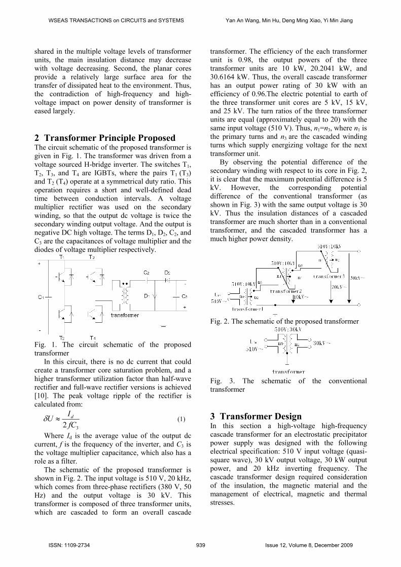
2 Transformer Principle Proposed The circuit schematic of the proposed transformer is
given in Fig. 1. The transformer was driven from a
voltage sourced H-bridge inverter. The switches T1,
T2, T3, and T4 are IGBTs, where the pairs T1 (T3)
and T2 (T4) operate at a symmetrical duty ratio. This
operation requires a short and well-defined dead
time between conduction intervals. A voltage
multiplier rectifier was used on the secondary
winding, so that the output dc voltage is twice the
secondary winding output voltage. And the output is
negative DC high voltage. The terms D1, D2, C2, and
C3 are the capacitances of voltage multiplier and the
diodes of voltage multiplier respectively.
Fig. 1. The circuit schematic of the proposed
transformer
In this circuit, there is no dc current that could
create a transformer core saturation problem, and a
higher transformer utilization factor than half-wave
rectifier and full-wave rectifier versions is achieved
[10]. The peak voltage ripple of the rectifier is
calculated from:
32 fC
IU d≈δ (1)
Where Id is the average value of the output dc
current, f is the frequency of the inverter, and C3 is
the voltage multiplier capacitance, which also has a
role as a filter.
The schematic of the proposed transformer is
shown in Fig. 2. The input voltage is 510 V, 20 kHz,
which comes from three-phase rectifiers (380 V, 50
Hz) and the output voltage is 30 kV. This
transformer is composed of three transformer units,
which are cascaded to form an overall cascade
transformer. The efficiency of the each transformer
unit is 0.98, the output powers of the three
transformer units are 10 kW, 20.2041 kW, and
30.6164 kW. Thus, the overall cascade transformer
has an output power rating of 30 kW with an
efficiency of 0.96.The electric potential to earth of
the three transformer unit cores are 5 kV, 15 kV,
and 25 kV. The turn ratios of the three transformer
units are equal (approximately equal to 20) with the
same input voltage (510 V). Thus, n1=n3, where n1 is
the primary turns and n3 are the cascaded winding
turns which supply energizing voltage for the next
transformer unit.
By observing the potential difference of the
secondary winding with respect to its core in Fig. 2,
it is clear that the maximum potential difference is 5
kV. However, the corresponding potential
difference of the conventional transformer (as
shown in Fig. 3) with the same output voltage is 30
kV. Thus the insulation distances of a cascaded
transformer are much shorter than in a conventional
transformer, and the cascaded transformer has a
much higher power density.
Fig. 2. The schematic of the proposed transformer
Fig. 3. The schematic of the conventional
transformer
3 Transformer Design In this section a high-voltage high-frequency
cascade transformer for an electrostatic precipitator
power supply was designed with the following
electrical specification: 510 V input voltage (quasi-
square wave), 30 kV output voltage, 30 kW output
power, and 20 kHz inverting frequency. The
cascade transformer design required consideration
of the insulation, the magnetic material and the
management of electrical, magnetic and thermal
stresses.
WSEAS TRANSACTIONS on CIRCUITS and SYSTEMS Yan An Wang, Min Hu, Deng Ming Xiao, Yi Min Jiang
ISSN: 1109-2734 939 Issue 12, Volume 8, December 2009
3.1 Magnetic Design The area product AP is the product of the winding
window area and the cross-sectional area of the core,
and it is a useful design parameter in selecting the
core and the number of turns per volt.
JfKB
PAP
um
t
4
104⋅
=
(2) where AP is the area product (cm
4), Pt is the
apparent power handling capability (W), Bm is the
maximum core flux density (T), f is the operating
frequency (Hz), Ku is the window utilization factor,
and J is the wire current density (A/cm2).
The planar ferrite EE type core ‘R 49938 EE’
from MAGNETICS Inc is selected for the cascade
transformer. The material of ‘R 49938 EE’ is
magnetic R-type material, which has low AC core
losses and decreasing losses to temperature of
100˚C. The dimensions of the core are shown in
Fig.4 and Table 1. The area product APEE of a pair
of EE is calculated from Fig. 4 and Table 1,
APEE=50.27 cm4. In this design, the parameters of
equation (2) were calculated or selected as follows:
Pt= 61.2412×10³ W, Bm=0.3 T (ferrite), f=20×10
3
Hz, Ku=0.3 and J=300 A/cm2. Hence, we obtained
AP=283.5241 cm4 from equation (2). Thus,
transformer unit 1 needs 6 pairs of ‘R 49938 EE’.
And same as the transformer unit 2, and transformer
unit 3 need 4 and 2 pairs of ‘R 49938 EE’
respectively.
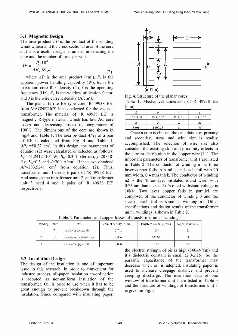
Fig. 4. Structure of the planar cores
Table 1: Mechanical dimension of R 49938 EE
(mm)
Once a core is chosen, the calculation of primary
and secondary turns and wire size is readily
accomplished. The selection of wire size also
considers the existing skin and proximity effects in
the current distribution in the copper wire [11]. The
important parameters of transformer unit 1 are listed
in Table 2. The conductor of winding n1 is three
layer copper foils in parallel and each foil with 20
mm width, 0.4 mm thick. The conductor of winding
n2 is the ‘three-layer insulated round wire’ with
0.75mm diameter and it’s rated withstand voltage is
10kV. Two layer copper foils in parallel are
composed of the conductor of winding 3 and the
size of each foil is same as winding n1. Other
specifications and design results of the transformer
unit 1 windings is shown in Table.2.
Table: 2 Parameters and copper losses of transformer unit 1 windings
3.2 Insulation Design The design of the insulation is one of important
issue in this research. In order to convenient for
industry process, oil-paper insulation co-ordination
is adopted as non-uniform insulation of the
transformer. Oil is prior to use when it has to be
great enough to prevent breakdown through the
insulation. Since compared with insulating paper,
the electric strength of oil is high (160kV/cm) and
it’s dielectric constant is small (2.0-2.25). So the
parasitic capacitance of the transformer may
decrease when oil is adopted. Insulating paper is
used to increase creepage distance and prevent
creeping discharge. The insulation data of one
window of transformer unit 1 are listed in Table 3
and the structure of windings of transformer unit 1
is given in Fig. 5.
WSEAS TRANSACTIONS on CIRCUITS and SYSTEMS Yan An Wang, Min Hu, Deng Ming Xiao, Yi Min Jiang
ISSN: 1109-2734 940 Issue 12, Volume 8, December 2009
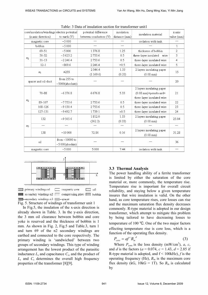
Table: 3 Data of insulation section for transformer unit1
Fig. 5. Structure of windings of transformer unit 1
In Fig.5, the insulation of the x-axis direction is
already shown in Table. 3. In the y-axis direction,
the 3 mm oil clearance between bobbin and core
yoke is reserved and the thickness of bobbin is 1
mm. As shown in Fig. 2, Fig.5 and Table.3, turn 1
and turn 69 of the n2 secondary windings are
earthed and connected to the core respectively. The
primary winding is ‘sandwiched’ between two
groups of secondary windings. This type of winding
arrangement has the lowest product of the parasitic
inductance Ls and capacitance Cs, and the product of
Ls and Cs determines the overall high frequency
properties of the transformer [8][9].
3.3 Thermal Analysis The power handling ability of a ferrite transformer
is limited by either the saturation of the core
material or, more commonly, the temperature rise.
Temperature rise is important for overall circuit
reliability, and staying below a given temperature
insures that wire insulation is valid. On the other
hand, as core temperature rises, core losses can rise
and the maximum saturation flux density decreases
commonly. R-type material is adopted in our design
transformer, which attempt to mitigate this problem
by being tailored to have decreasing losses to
temperature of 100 . One of the two major factors
effecting temperature rise is core loss, which is a
function of the operating flux density. d
m
c
core BafP = (3)
Where Pcore is the loss density (mW/cm3), a, c,
and d is the factors (a = 0.074, c = 1.43, d = 2.85 if
R-type material is adopted, and f < 100kHz), f is the
operating frequency (Hz), Bm is the maximum core
flux density (kG, 10kG = 1T). So Bm is calculated
by
WSEAS TRANSACTIONS on CIRCUITS and SYSTEMS Yan An Wang, Min Hu, Deng Ming Xiao, Yi Min Jiang
ISSN: 1109-2734 941 Issue 12, Volume 8, December 2009
8
1
'104 −×
=fNA
EB
c
m (4)
where E is the applied voltage of primary
windings (V), A’c is the core area (cm
2), N1 is the
number of turns of primary windings, f is the
operating frequency (Hz).
The Bm and Pcore can be calculated according the
datum of Table.1 and Table.2, namely, Bm = 2.891
kG, Pcore = 110.584 mW/cm3. With reference to Fig.
4, the total volume of the six pairs of ‘R 49938 EE’
is approximation to 478.8 cm3. Thus, the total core
losses are 53 W. Copper loss is the second major
contributor to temperature rise. According to Table.
2 the total copper losses of the windings was 47 W.
Furthermore, the overall total losses are 100 W. For
this situation, the power dissipation of transformer
unit 1 is below 1% of the total output power.
The core shape also affects temperature and
those that dissipate heat well are desirable. The
planar cascade transformer is different with the
conventional transformer in switching-mode power
converters. The fluid encapsulation such as
transformer oil was considered. Transformer oil is a
good medium for heat transport. Under ideal natural
convection conditions it has heat transfer coefficient
of approximately 95 W.m-2
K-1
; this is equivalent to
forced air-cooling with a flow velocity of
approximately 25 m/s [2]. On the other hand, Oil
cooling has many merits as follows:
It is favorable for improving the cooling,
especially when multiple planar transformers
are paralleled to form a higher power
transformer (this type of transformer is easy
to integrate which will be shown later).
It is favorable for enhancing the insulation of
the planar transformer (the insulation
strength of oil is 16 kV/mm).
Compared with sulfur hexafluoride,
transformer oil has little or no greenhouse
effect.
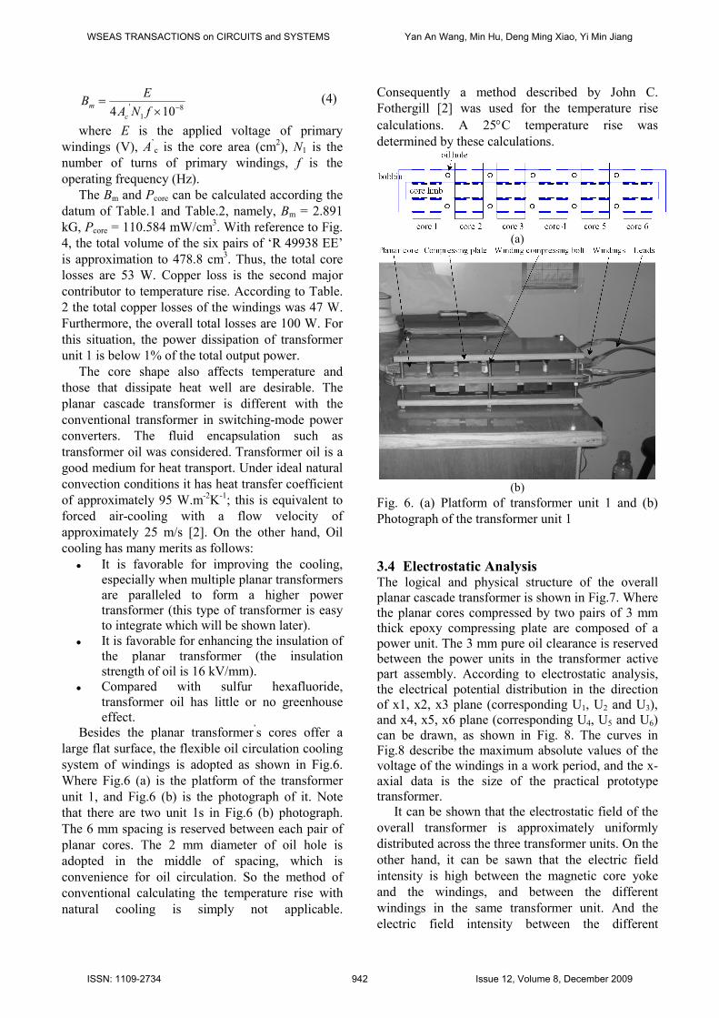
Besides the planar transformer’s cores offer a
large flat surface, the flexible oil circulation cooling
system of windings is adopted as shown in Fig.6.
Where Fig.6 (a) is the platform of the transformer
unit 1, and Fig.6 (b) is the photograph of it. Note
that there are two unit 1s in Fig.6 (b) photograph.
The 6 mm spacing is reserved between each pair of
planar cores. The 2 mm diameter of oil hole is
adopted in the middle of spacing, which is
convenience for oil circulation. So the method of
conventional calculating the temperature rise with
natural cooling is simply not applicable.
Consequently a method described by John C.
Fothergill [2] was used for the temperature rise
calculations. A 25°C temperature rise was
determined by these calculations.
(a)
(b)
Fig. 6. (a) Platform of transformer unit 1 and (b)
Photograph of the transformer unit 1
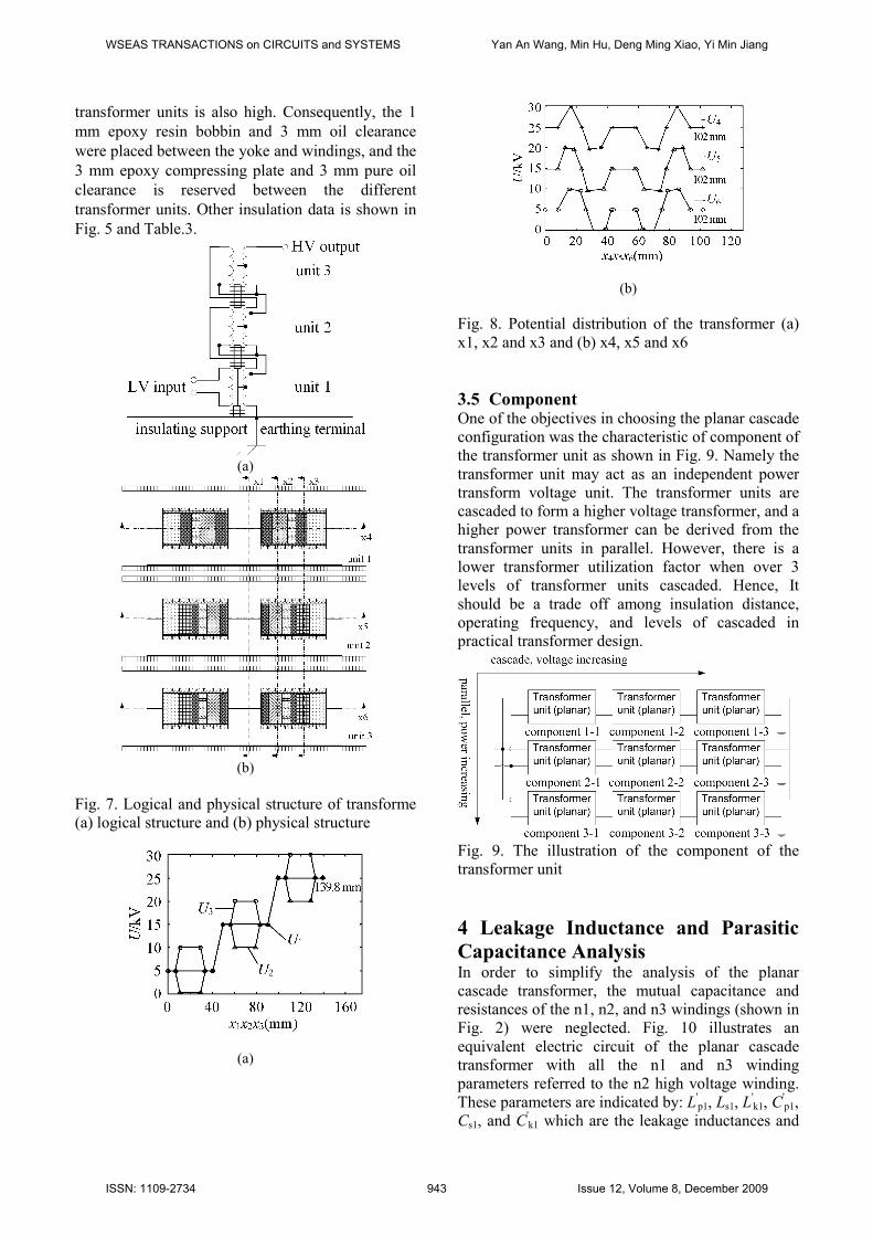
3.4 Electrostatic Analysis The logical and physical structure of the overall
planar cascade transformer is shown in Fig.7. Where
the planar cores compressed by two pairs of 3 mm
thick epoxy compressing plate are composed of a
power unit. The 3 mm pure oil clearance is reserved
between the power units in the transformer active
part assembly. According to electrostatic analysis,
the electrical potential distribution in the direction
of x1, x2, x3 plane (corresponding U1, U2 and U3),
and x4, x5, x6 plane (corresponding U4, U5 and U6)
can be drawn, as shown in Fig. 8. The curves in
Fig.8 describe the maximum absolute values of the
voltage of the windings in a work period, and the x-
axial data is the size of the practical prototype
transformer.
It can be shown that the electrostatic field of the
overall transformer is approximately uniformly
distributed across the three transformer units. On the
other hand, it can be sawn that the electric field
intensity is high between the magnetic core yoke
and the windings, and between the different
windings in the same transformer unit. And the
electric field intensity between the different
WSEAS TRANSACTIONS on CIRCUITS and SYSTEMS Yan An Wang, Min Hu, Deng Ming Xiao, Yi Min Jiang
ISSN: 1109-2734 942 Issue 12, Volume 8, December 2009
transformer units is also high. Consequently, the 1
mm epoxy resin bobbin and 3 mm oil clearance
were placed between the yoke and windings, and the
3 mm epoxy compressing plate and 3 mm pure oil
clearance is reserved between the different
transformer units. Other insulation data is shown in
Fig. 5 and Table.3.
(a)
(b)
Fig. 7. Logical and physical structure of transforme
(a) logical structure and (b) physical structure
(a)
(b)
Fig. 8. Potential distribution of the transformer (a)
x1, x2 and x3 and (b) x4, x5 and x6
3.5 Component One of the objectives in choosing the planar cascade
configuration was the characteristic of component of
the transformer unit as shown in Fig. 9. Namely the
transformer unit may act as an independent power
transform voltage unit. The transformer units are
cascaded to form a higher voltage transformer, and a
higher power transformer can be derived from the
transformer units in parallel. However, there is a
lower transformer utilization factor when over 3
levels of transformer units cascaded. Hence, It
should be a trade off among insulation distance,
operating frequency, and levels of cascaded in
practical transformer design.
Fig. 9. The illustration of the component of the
transformer unit
4 Leakage Inductance and Parasitic
Capacitance Analysis In order to simplify the analysis of the planar
cascade transformer, the mutual capacitance and
resistances of the n1, n2, and n3 windings (shown in
Fig. 2) were neglected. Fig. 10 illustrates an
equivalent electric circuit of the planar cascade
transformer with all the n1 and n3 winding
parameters referred to the n2 high voltage winding.
These parameters are indicated by: L'p1, Ls1, L
'k1, C
'p1,
Cs1, and C'k1 which are the leakage inductances and
WSEAS TRANSACTIONS on CIRCUITS and SYSTEMS Yan An Wang, Min Hu, Deng Ming Xiao, Yi Min Jiang
ISSN: 1109-2734 943 Issue 12, Volume 8, December 2009
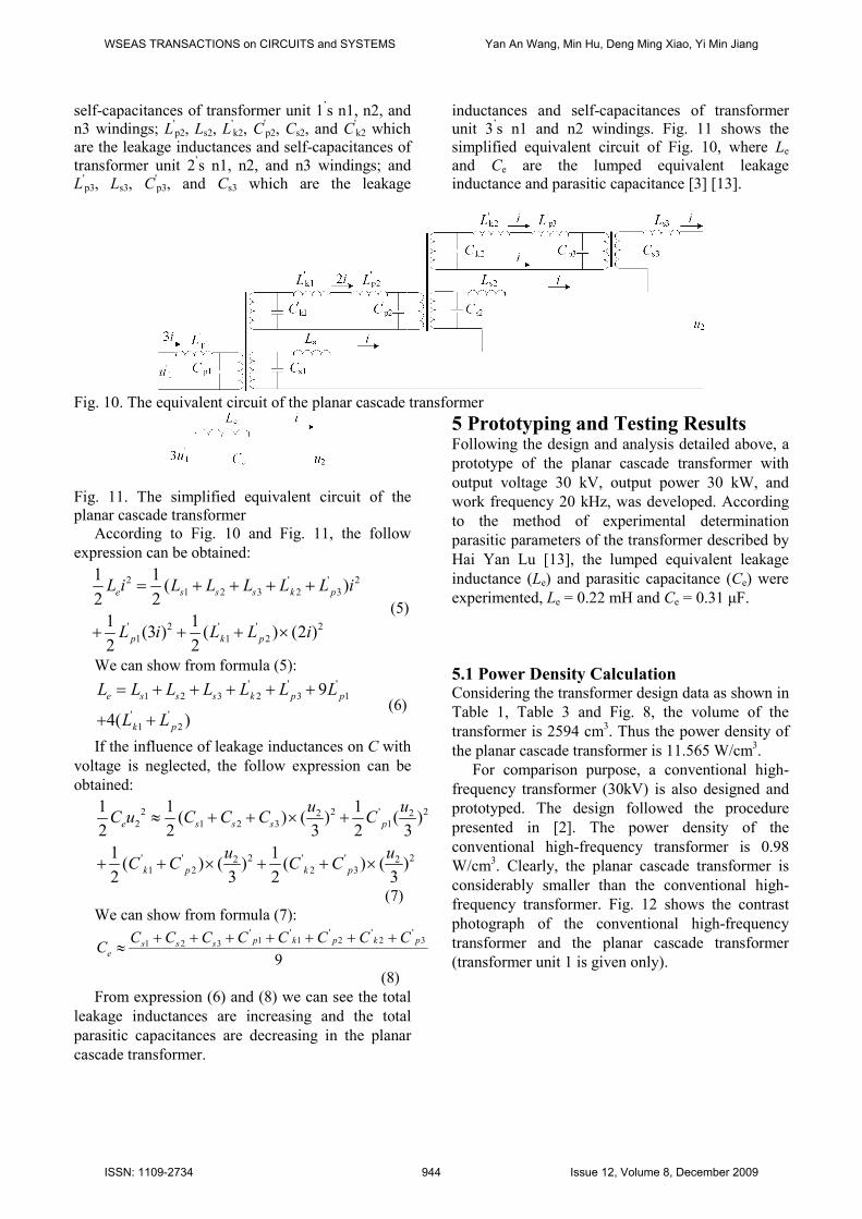
self-capacitances of transformer unit 1’s n1, n2, and
n3 windings; L'p2, Ls2, L
'k2, C
'p2, Cs2, and C
'k2 which
are the leakage inductances and self-capacitances of
transformer unit 2’s n1, n2, and n3 windings; and
L'p3, Ls3, C
'p3, and Cs3 which are the leakage
inductances and self-capacitances of transformer
unit 3’s n1 and n2 windings. Fig. 11 shows the
simplified equivalent circuit of Fig. 10, where Le
and Ce are the lumped equivalent leakage
inductance and parasitic capacitance [3] [13].
Fig. 10. The equivalent circuit of the planar cascade transformer
Fig. 11. The simplified equivalent circuit of the
planar cascade transformer
According to Fig. 10 and Fig. 11, the follow
expression can be obtained:
2 ' ' 2
1 2 3 2 3
' 2 ' ' 2
1 1 2
1 1( )
2 2
1 1(3 ) ( ) (2 )
2 2
e s s s k p
p k p
L i L L L L L i
L i L L i
= + + + +
+ + + ×
(5)
We can show from formula (5): ' ' '
1 2 3 2 3 1
' '
1 2
9
4( )
e s s s k p p
k p
L L L L L L L
L L
= + + + + +
+ +
(6)
If the influence of leakage inductances on C with
voltage is neglected, the follow expression can be
obtained:
2 2 ' 22 22 1 2 3 1
' ' 2 ' ' 22 21 2 2 3
1 1 1( ) ( ) ( )
2 2 3 2 3
1 1( ) ( ) ( ) ( )
2 3 2 3
e s s s p
k p k p
u uC u C C C C
u uC C C C
≈ + + × +
+ + × + + ×
(7)
We can show from formula (7):
9
3'
2'
2'
1'
1'
321 pkpkpssse
CCCCCCCCC
+++++++≈
(8)
From expression (6) and (8) we can see the total
leakage inductances are increasing and the total
parasitic capacitances are decreasing in the planar
cascade transformer.
5 Prototyping and Testing Results Following the design and analysis detailed above, a
prototype of the planar cascade transformer with
output voltage 30 kV, output power 30 kW, and
work frequency 20 kHz, was developed. According
to the method of experimental determination
parasitic parameters of the transformer described by
Hai Yan Lu [13], the lumped equivalent leakage
inductance (Le) and parasitic capacitance (Ce) were
experimented, Le = 0.22 mH and Ce = 0.31 µF.
5.1 Power Density Calculation Considering the transformer design data as shown in
Table 1, Table 3 and Fig. 8, the volume of the
transformer is 2594 cm3. Thus the power density of
the planar cascade transformer is 11.565 W/cm3.
For comparison purpose, a conventional high-
frequency transformer (30kV) is also designed and
prototyped. The design followed the procedure
presented in [2]. The power density of the
conventional high-frequency transformer is 0.98
W/cm3. Clearly, the planar cascade transformer is
considerably smaller than the conventional high-
frequency transformer. Fig. 12 shows the contrast
photograph of the conventional high-frequency
transformer and the planar cascade transformer
(transformer unit 1 is given only).
WSEAS TRANSACTIONS on CIRCUITS and SYSTEMS Yan An Wang, Min Hu, Deng Ming Xiao, Yi Min Jiang
ISSN: 1109-2734 944 Issue 12, Volume 8, December 2009
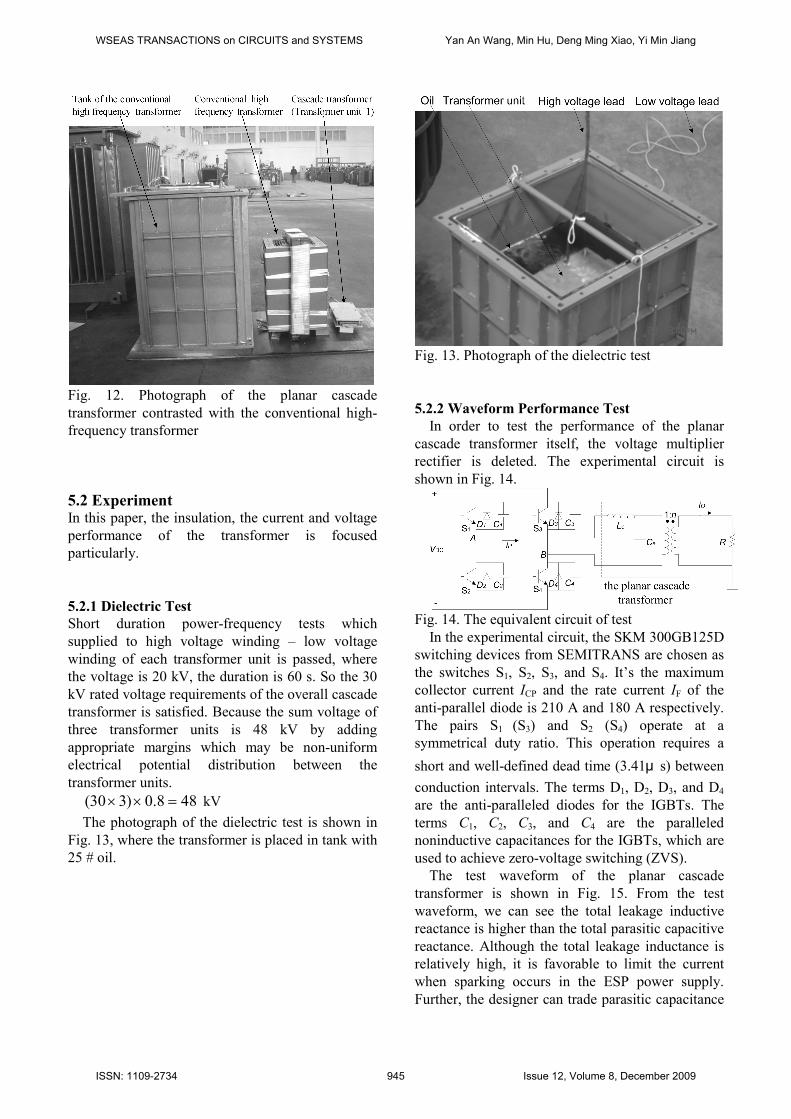
Fig. 12. Photograph of the planar cascade
transformer contrasted with the conventional high-
frequency transformer
5.2 Experiment In this paper, the insulation, the current and voltage
performance of the transformer is focused
particularly.
5.2.1 Dielectric Test
Short duration power-frequency tests which
supplied to high voltage winding – low voltage
winding of each transformer unit is passed, where
the voltage is 20 kV, the duration is 60 s. So the 30
kV rated voltage requirements of the overall cascade
transformer is satisfied. Because the sum voltage of
three transformer units is 48 kV by adding
appropriate margins which may be non-uniform
electrical potential distribution between the
transformer units.
488.0)330( =×× kV
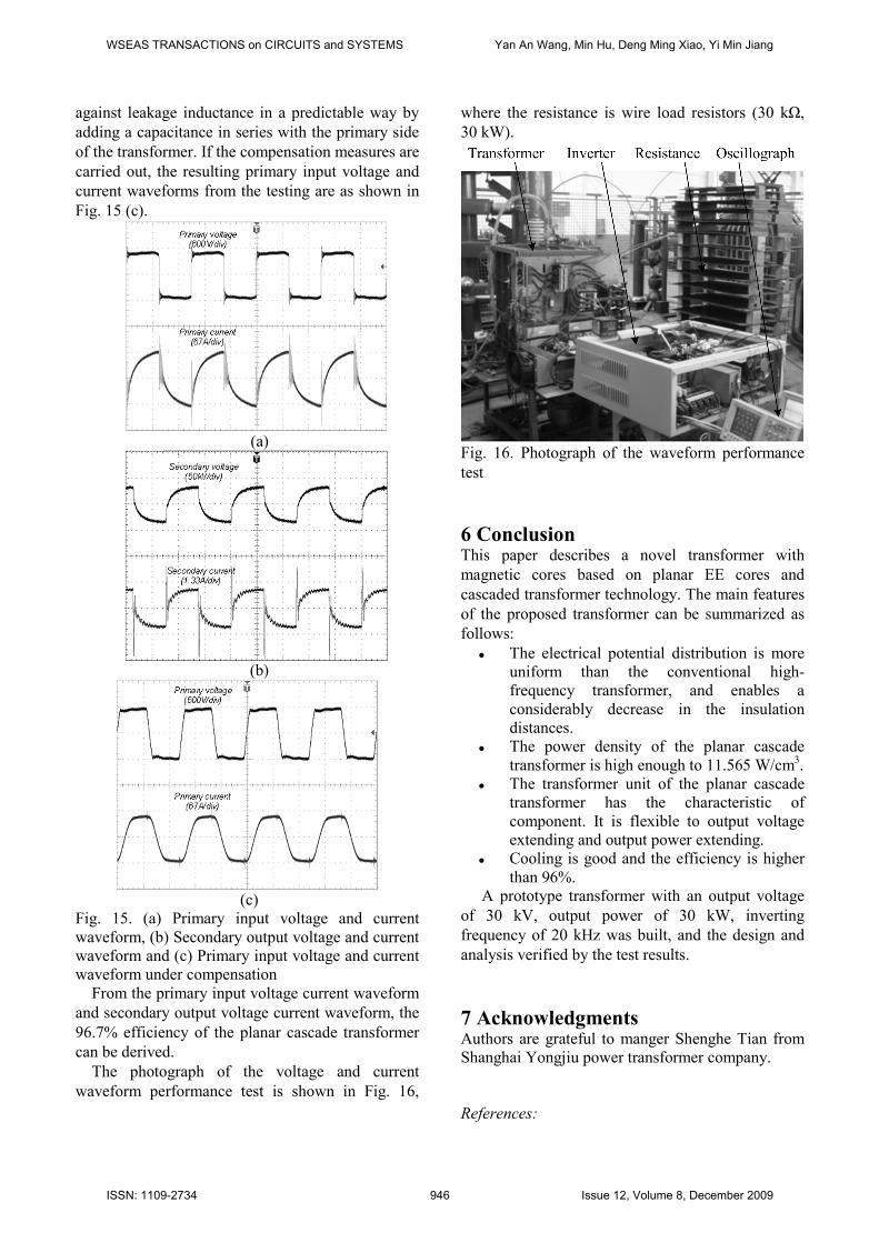
The photograph of the dielectric test is shown in
Fig. 13, where the transformer is placed in tank with
25 # oil.
Fig. 13. Photograph of the dielectric test
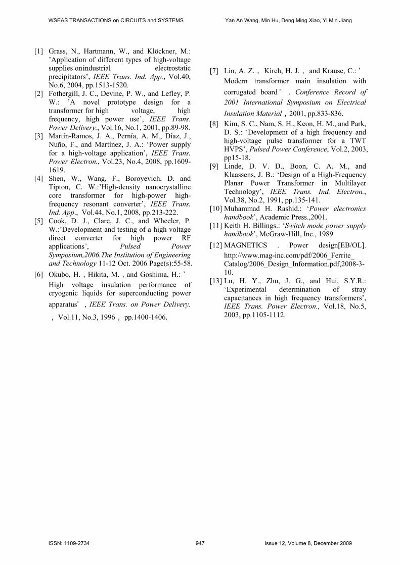
5.2.2 Waveform Performance Test
In order to test the performance of the planar
cascade transformer itself, the voltage multiplier
rectifier is deleted. The experimental circuit is
shown in Fig. 14.
Fig. 14. The equivalent circuit of test
In the experimental circuit, the SKM 300GB125D
switching devices from SEMITRANS are chosen as
the switches S1, S2, S3, and S4. It’s the maximum
collector current ICP and the rate current IF of the
anti-parallel diode is 210 A and 180 A respectively.
The pairs S1 (S3) and S2 (S4) operate at a
symmetrical duty ratio. This operation requires a
short and well-defined dead time (3.41μ s) between
conduction intervals. The terms D1, D2, D3, and D4
are the anti-paralleled diodes for the IGBTs. The
terms C1, C2, C3, and C4 are the paralleled
noninductive capacitances for the IGBTs, which are
used to achieve zero-voltage switching (ZVS).
The test waveform of the planar cascade
transformer is shown in Fig. 15. From the test
waveform, we can see the total leakage inductive
reactance is higher than the total parasitic capacitive
reactance. Although the total leakage inductance is
relatively high, it is favorable to limit the current
when sparking occurs in the ESP power supply.
Further, the designer can trade parasitic capacitance
WSEAS TRANSACTIONS on CIRCUITS and SYSTEMS Yan An Wang, Min Hu, Deng Ming Xiao, Yi Min Jiang
ISSN: 1109-2734 945 Issue 12, Volume 8, December 2009
against leakage inductance in a predictable way by
adding a capacitance in series with the primary side
of the transformer. If the compensation measures are
carried out, the resulting primary input voltage and
current waveforms from the testing are as shown in
Fig. 15 (c).
(a)
(b)
(c)
Fig. 15. (a) Primary input voltage and current
waveform, (b) Secondary output voltage and current
waveform and (c) Primary input voltage and current
waveform under compensation
From the primary input voltage current waveform
and secondary output voltage current waveform, the
96.7% efficiency of the planar cascade transformer
can be derived.
The photograph of the voltage and current
waveform performance test is shown in Fig. 16,
where the resistance is wire load resistors (30 kΩ,
30 kW).
Fig. 16. Photograph of the waveform performance
test
6 Conclusion This paper describes a novel transformer with
magnetic cores based on planar EE cores and
cascaded transformer technology. The main features
of the proposed transformer can be summarized as
follows:
The electrical potential distribution is more
uniform than the conventional high-
frequency transformer, and enables a
considerably decrease in the insulation
distances.
The power density of the planar cascade
transformer is high enough to 11.565 W/cm3.
The transformer unit of the planar cascade
transformer has the characteristic of
component. It is flexible to output voltage
extending and output power extending.
Cooling is good and the efficiency is higher
than 96%.
A prototype transformer with an output voltage
of 30 kV, output power of 30 kW, inverting
frequency of 20 kHz was built, and the design and
analysis verified by the test results.
7 Acknowledgments Authors are grateful to manger Shenghe Tian from
Shanghai Yongjiu power transformer company.
References:
WSEAS TRANSACTIONS on CIRCUITS and SYSTEMS Yan An Wang, Min Hu, Deng Ming Xiao, Yi Min Jiang
ISSN: 1109-2734 946 Issue 12, Volume 8, December 2009
[1] Grass, N., Hartmann, W., and Klöckner, M.:
’Application of different types of high-voltage
supplies on industrial electrostatic
precipitators’, IEEE Trans. Ind. App., Vol.40,
No.6, 2004, pp.1513-1520.
[2] Fothergill, J. C., Devine, P. W., and Lefley, P.
W.: ’A novel prototype design for a
transformer for high voltage, high
frequency, high power use’, IEEE Trans.
Power Delivery., Vol.16, No.1, 2001, pp.89-98.
[3] Martin-Ramos, J. A., Pernía, A. M., Díaz, J.,
Nuño, F., and Martínez, J. A.: ‘Power supply
for a high-voltage application’, IEEE Trans.
Power Electron., Vol.23, No.4, 2008, pp.1609-
1619.
[4] Shen, W., Wang, F., Boroyevich, D. and
Tipton, C. W.:’High-density nanocrystalline
core transformer for high-power high-
frequency resonant converter’, IEEE Trans.
Ind. App., Vol.44, No.1, 2008, pp.213-222.
[5] Cook, D. J., Clare, J. C., and Wheeler, P.
W.:’Development and testing of a high voltage
direct converter for high power RF
applications’, Pulsed Power
Symposium,2006.The Institution of Engineering
and Technology 11-12 Oct. 2006 Page(s):55-58.
[6] Okubo, H.,Hikita, M.,and Goshima, H.: ’High voltage insulation performance of
cryogenic liquids for superconducting power
apparatus’ , IEEE Trans. on Power Delivery.
, Vol.11, No.3, 1996, pp.1400-1406.
[7] Lin, A. Z., Kirch, H. J., and Krause, C.: ’Modern transformer main insulation with
corrugated board ’ . Conference Record of
2001 International Symposium on Electrical
Insulation Material,2001, pp.833-836.
[8] Kim, S. C., Nam, S. H., Keon, H. M., and Park,
D. S.: ‘Development of a high frequency and
high-voltage pulse transformer for a TWT
HVPS’, Pulsed Power Conference, Vol.2, 2003,
pp15-18.
[9] Linde, D. V. D., Boon, C. A. M., and
Klaassens, J. B.: ‘Design of a High-Frequency
Planar Power Transformer in Multilayer
Technology’, IEEE Trans. Ind. Electron.,
Vol.38, No.2, 1991, pp.135-141.
[10] Muhammad H. Rashid.: ‘Power electronics
handbook’, Academic Press.,2001.
[11] Keith H. Billings.: ‘Switch mode power supply
handbook’, McGraw-Hill, Inc., 1989
[12] MAGNETICS . Power design[EB/OL].
http://www.mag-inc.com/pdf/2006_Ferrite_
Catalog/2006_Design_Information.pdf,2008-3-
10.
[13] Lu, H. Y., Zhu, J. G., and Hui, S.Y.R.:
‘Experimental determination of stray
capacitances in high frequency transformers’,
IEEE Trans. Power Electron., Vol.18, No.5,
2003, pp.1105-1112.
WSEAS TRANSACTIONS on CIRCUITS and SYSTEMS Yan An Wang, Min Hu, Deng Ming Xiao, Yi Min Jiang
ISSN: 1109-2734 947 Issue 12, Volume 8, December 2009