Embed Size (px)
Citation preview
Delft University of Technology
Design of a Haptic Feedback System for Flight Envelope Protection
Van Baelen, Dirk; Ellerbroek, Joost; van Paassen, Rene; Mulder, Max
DOI10.2514/1.G004596Publication date2020Document VersionFinal published versionPublished inJournal of Guidance, Control, and Dynamics: devoted to the technology of dynamics and control
Citation (APA)Van Baelen, D., Ellerbroek, J., van Paassen, R., & Mulder, M. (2020). Design of a Haptic Feedback Systemfor Flight Envelope Protection. Journal of Guidance, Control, and Dynamics: devoted to the technology ofdynamics and control, 43(4), 700-714. https://doi.org/10.2514/1.G004596
Important noteTo cite this publication, please use the final published version (if applicable).Please check the document version above.
CopyrightOther than for strictly personal use, it is not permitted to download, forward or distribute the text or part of it, without the consentof the author(s) and/or copyright holder(s), unless the work is under an open content license such as Creative Commons.
Takedown policyPlease contact us and provide details if you believe this document breaches copyrights.We will remove access to the work immediately and investigate your claim.
This work is downloaded from Delft University of Technology.For technical reasons the number of authors shown on this cover page is limited to a maximum of 10.
Design of a Haptic Feedback Systemfor Flight Envelope Protection
Dirk Van Baelen,∗ Joost Ellerbroek,† M. M. (René) van Paassen,‡ and Max Mulder§
Delft University of Technology, 2629 HS Delft, The Netherlands
https://doi.org/10.2514/1.G004596
Several modern aircraft use a passive control manipulator: a spring–damper system that generates command
signals to the flight control computers in combination with a flight envelope protection system that limits pilot inputs
when approaching the aircraft limits. This research project aims to increase pilot awareness of this protection system
through the use of force feedback on the control device, that is, haptics. This paper describes in detail how the haptic
feedback works and when it triggers; another paper will discuss the results of an experimental evaluation. With the
current haptic design, pilots can get five cues: first, a discrete force cue when approaching the limits; second, an
increased spring coefficient for control deflections that bring the aircraft closer to its limits; third, a stick shaker for
low velocities; fourth, if a low-velocity condition requires an input, the stick is moved forward to the desired control
input; and finally, the stick follows the automatic Airbus “pitch-up” command during an overspeed condition. This
novel system is expected to help pilots correctly assess the situation and decide upon the right control action. It will
be evaluated in two scenarios close to the flight envelope limits: a windshear and an icing event.
Nomenclature
a = acceleration, m∕s2CL = lift coefficientD = drag, NF = force, Ng = gravitational acceleration, m∕s2K = gaink = spring, N∕radL = lift, Nm = mass, kgn = load factor, gq = pitch rate, rad∕sS = surface, m2
T = thrust, Nt = time, sV = velocity, m∕sW = weight, Nα = angle of attack, radβ = sideslip angle, radγ = flight path angle, radδ = control device deflection, radθ = pitch angle, radρ = density, kg∕m3
φ = roll angle, rad
Subscripts
br = breakoutmax = maximum valuemin = minimum value
nom = nominal valuenp = neutral pointprot = protected region value
I. Introduction
M ODERN cockpits provide an abundance of information topilots, primarily using the visual and auditory communication
channels. Examples of visual displays are the primary flight display(PFD) for the most important aircraft states and the navigation dis-play for a planar top-down overview of the environment. Auditorysignals are often used to provide urgent messages, such as to warnpilots for too high velocities and to provide altitude readouts andthrottle back commands on landing [1].But, apart from these senses, pilots are able to perceive information
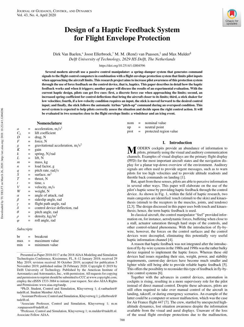
in several other ways. This paper will elaborate on the use of thepilot’s haptic sense by providing haptic feedback through the controldevice. As shown in Fig. 1, within the field of haptic research, twomain categories are identified: touch (stimuli to the skin) and kinaes-thesis (stimuli to the receptors in the muscles, joints, and tendons)[2,3]. The design discussed in this paper uses both touch and kinaes-thesis; hence, the term haptic feedback is used.In classical aircraft, the control manipulator “feel” provided infor-
mation on, for instance, aerodynamic forces, buffeting when close toa stall, actuator saturation through hard stops of the controls, andother control-related phenomena. With the introduction of fly-by-wire, however, the forces on the control surfaces and the controldevices were decoupled, eliminating this potentially very usefulhaptic information channel [4].A reason that haptic feedback was not integrated after the introduc-
tion of fly-by-wire systems in the 1980s and1990swas the rather bulkydevice required to implement the haptic forces. Whereas these olddevices had issues regarding their size, weight, power, and stabilityrequirements, current-day devices have become much smaller andlighter while still being able to provide reliable haptic feedback [5].This offers the possibility to reconsider this type of feedback in fly-by-wire control systems [6].Together with the advances in control devices, automation in
cockpits is rising, resulting in a more supervisory role for the pilotinstead of direct manual control. Despite these advances, pilots arestill often required to take over manual control of the aircraft inlanding, takeoff, or during emergency scenarios. An example of thelatter could be a computer or sensor malfunction, which was the casefor Air France flight 447 [7]. The crew, startled by unexpected high-altitude dynamics, lost situation awareness despite the informationavailable from the visual and aural displays. Unaware of the lossof the usual flight envelope protections due to the malfunction,
Presented as Paper 2018-0117 at the 2018AIAAModeling and SimulationTechnologies Conference, Kissimmee, FL, 8–12 January 2018; received 29May 2019; revision received 30 October 2019; accepted for publication 5November 2019; published online 28 February 2020. Copyright © 2019 byDelft University of Technology. Published by the American Institute ofAeronautics and Astronautics, Inc., with permission. All requests for copyingand permission to reprint should be submitted to CCC atwww.copyright.com;employ the eISSN 1533-3884 to initiate your request. See also AIAA Rightsand Permissions www.aiaa.org/randp.
*Ph.D. Student, Control and Simulation, Kluyverweg 1; [email protected]. Student Member AIAA.
†Assistant Professor, Control andSimulation,Kluyverweg1; [email protected].
‡Associate Professor, Control and Simulation, Kluyverweg 1; [email protected].
§Professor, Control and Simulation, Kluyverweg 1; [email protected] Fellow AIAA.
700
JOURNAL OF GUIDANCE, CONTROL, AND DYNAMICS
Vol. 43, No. 4, April 2020
Dow
nloa
ded
by T
U D
EL
FT o
n M
arch
26,
202
0 | h
ttp://
arc.
aiaa
.org
| D
OI:
10.
2514
/1.G
0045
96
pilots stalled the aircraft. The control manipulator, which was theAirbus A330 sidestick, provided the pilots with neither direct feed-back on their control actions nor the aerodynamic stall buffets; i.e., itdid not help them in properly identifying the situation as a stall. Asthis tragic example shows, whenmanual control is needed, the lack ofhaptic information through the control device might contribute to areduced situation awareness.Combining the ever-increasing sophistication of automation on the
flight deck and the current generation of small and powerful controldevices provides designers a new opportunity, namely, to increasepilot awareness through haptic feedback. Some aircraft alreadyinclude “augmented forces” on the control device, which can beprovided on both control devices (in a two-pilot cockpit) linked tothe surfaces or fly-by-wire control systems. An example of this is the“Q-feel force,” which changes the stiffness of the controls withchanging dynamic pressure/velocity in Boeing-type aircraft [8].Another example is a stick shaker or pusher, which warns pilots ofmoving closer to extreme aircraft states [9]. The control device canalso be loaded with two passive springs to create a change in springcoefficient when pilots exert large control deflections, irrespective ofthe aircraft state, such as done inAirbus aircraft. Active control can beused to have an increased (artificial) spring forcewhen rolling beyondthe safe roll limit, irrespective of the control surfaces, as used in aBoeing 777 [10].Although examples of haptic feedback implementations exist,
there is limited research published in the open literature to provethe benefits of such a system. Within the field of aerospace, oneexample uses a passive spring or an active counterforce to commu-nicate the distance to the flight envelope limits. The latter gave thebest tracking performance increase as compared to the baselinecondition [11]. A second example is the work by Stepanyan et al.that showed the limit on the available control space both visually andhaptically [12]. For the haptics, they changed the input neutral pointand the maximum deflection, which was used by the pilots to operatethe aircraft at the limits. A soft stop (i.e., a local step in the forcerequired for a certain deflection) can be used to indicate the enginelimitations in the collective of a helicopter. It was shown in simu-lations that such a system can reduce the workload of the pilot[13,14]; this was implemented in an experimental helicopter of theDLR, German Aerospace Center [15]. Tactile feedback through theuse of vibrating elements on a vest, i.e. tactors, enabled spatialawareness and reduced spatial disorientation [16]. These examplesuse haptic feedback to inform the pilot about the flight envelopelimits. Note that research in supplying the pilot with such informationis not limited to haptic only; new visual displays are investigated aswell and show positive results [17]. Aside from information on theflight envelope limits, the haptic channel can additionally be used tosupply guidance support, of which a haptic flight director showedgreat potential to increase the pilot tracking error and reduce work-load [18]. Other fields do show a larger public research interest in thisdomain, for example, in teleoperation: the control of an unmannedvehiclewas supported by haptically showing the proximity to objectsin its surroundings. It resulted in decreased workload and increasedsituation awareness for the given navigation task [19]. In the auto-motive field, haptics can be used on the gas pedal to show theproximity of a car in front, resulting in an increased performancewhile reducing input magnitudes [20]. Haptics can additionally beused to support curve negotiation through the steering wheel usingtwo approaches: i) warning systemswhich reduce the reaction time of
the driver while have a potential to induce driver-annoyance, and ii)guidance systems (for example to the center of the road) improvedperformance yet are subjective to after-effects [21].The aim of the current project is to investigate the use of haptic
feedback to give the pilot more information on the augmentationwithrespect to the limits of the aircraft during manual control within themodern fly-by-wire cockpit. In other words, the design presented inthe following aims to provide feedback to the pilot on the proximityof the state to the flight envelope limits. Only longitudinal hapticfeedback is considered here; lateral cues can be added in a futuredesign using the same design ideas. This work builds on an initialstudy [22], which already showed a potential benefit of such a hapticfeedback system. The goal of this paper is to elaborate on a newiteration and give a thorough description on the how and when of thehaptics, as well as the expected practical implications.Section II will first discuss some basic flight dynamics and will
introduce the control laws and flight envelope protection systempresent in current fly-by-wire Airbus aircraft. Section III discussesthe rationale of our haptic interface, which is designed to presentsome of the functions of these automated systems. We then discusstwo operational scenarios where the flight envelope protection sys-tem will trigger (a windshear and an icing event) to explain in detailhow our haptic interface works (Sec. IV). Finally, conclusions aregiven in Sec. V.
II. Flight Dynamics and Control Laws
This section provides the background needed to understand thedesign rationale of our haptic interface. Section II.A covers somebasic flight dynamics properties and variables. Readers familiar withaircraft flight dynamics can skip this subsection. Because our hapticdesign focuses on supporting pilots in working with the complexAirbus control law and flight envelope protection structures, a briefrecap of these structures is provided in Sec. II.B. This recap onlydiscusses the (highly coupled) protections; yet, the level of detail issufficient to support the design of the haptic feedback system in thefollowing.
A. Flight Dynamics
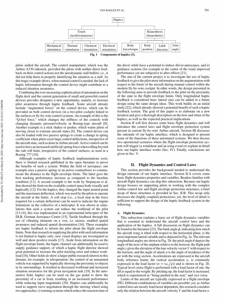
This subsection explains a basic set of flight dynamics variablesthat is essential to understand the aircraft control laws and theapplication of the haptics. A full discussion on flight dynamics canbe found in the literature [23]. The bank angleϕ, indicating howmuchthe aircraft wing is tilted with respect to the horizontal plane, is themost important lateral variable and is depicted in Fig. 2a. The relevantlongitudinal angles are shown in Fig. 2b: the pitch angle θ depicts theangle of the nose of the airplane relative to the horizon, the flight pathangle γ gives the elevation of the true velocity vectorV with respect tothe horizon, and the angle of attack α is the angle of incidence of theair with the wing section. Accelerations are expressed in the aircraftbody reference frame; the vertical acceleration az is commonlyexpressed in the load factor (n � �az∕g�) and is shown in Fig. 2b.Typical level cruise flight is performed with a load factor of one: thelift is equal to theweight. By pitching up, the load factor is increased,which is experienced as “being pushed in the seat,” and vice versa.Limits of the aircraft are typically expressed in a flight envelope
(FE). Different combinations of variables are possible; yet, as Airbuscontrol laws aremostly load factor dependent, this research considersonly the relation between the aircraft velocityV and the load factor n.
Haptics
Touch(tactile/cutaneous)
Kinaesthesis(kinaesthetic)
Mechanicalstimulation
Thermalstimulation
Chemicalstimulation
Electricalstimulation
Bodyforce/torque
Bodyposition
Limbdirection
Jointangle
Fig. 1 Components of haptics [3].
VAN BAELEN ETAL. 701
Dow
nloa
ded
by T
U D
EL
FT o
n M
arch
26,
202
0 | h
ttp://
arc.
aiaa
.org
| D
OI:
10.
2514
/1.G
0045
96
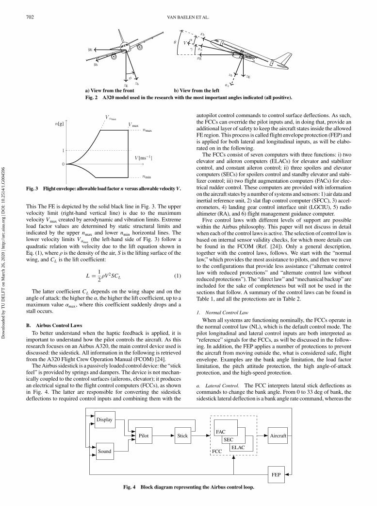
This The FE is depicted by the solid black line in Fig. 3. The uppervelocity limit (right-hand vertical line) is due to the maximumvelocity Vmax created by aerodynamic and vibration limits. Extremeload factor values are determined by static structural limits andindicated by the upper nmax and lower nmin horizontal lines. Thelower velocity limits Vαmax
(the left-hand side of Fig. 3) follow aquadratic relation with velocity due to the lift equation shown inEq. (1), where ρ is the density of the air, S is the lifting surface of thewing, and CL is the lift coefficient:
L � 1
2ρV2SCL (1)
The latter coefficient CL depends on the wing shape and on theangle of attack: the higher the α, the higher the lift coefficient, up to amaximum value αmax, where this coefficient suddenly drops and astall occurs.
B. Airbus Control Laws
To better understand when the haptic feedback is applied, it isimportant to understand how the pilot controls the aircraft. As thisresearch focuses on an Airbus A320, the main control device used isdiscussed: the sidestick. All information in the following is retrievedfrom the A320 Flight Crew Operation Manual (FCOM) [24].TheAirbus sidestick is a passively loaded control device: the “stick
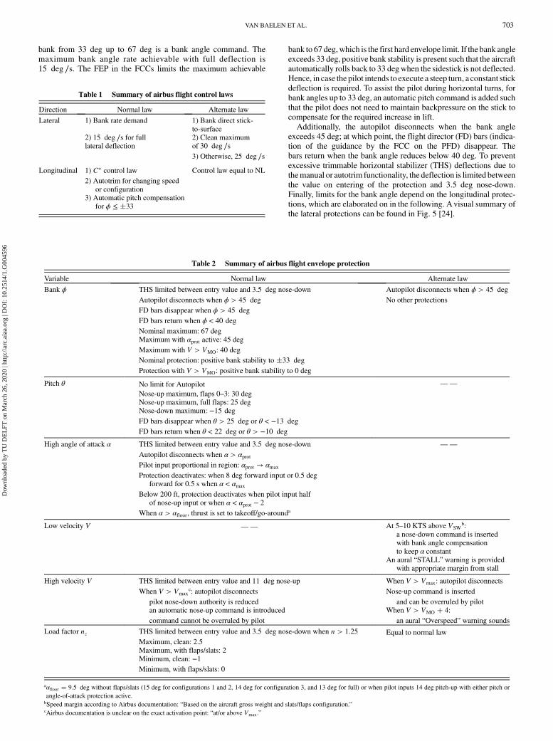
feel” is provided by springs and dampers. The device is not mechan-ically coupled to the control surfaces (ailerons, elevator); it producesan electrical signal to the flight control computers (FCCs), as shownin Fig. 4. The latter are responsible for converting the sidestickdeflections to required control inputs and combining them with the
autopilot control commands to control surface deflections. As such,the FCCs can override the pilot inputs and, in doing that, provide anadditional layer of safety to keep the aircraft states inside the allowedFE region. This process is called flight envelope protection (FEP) andis applied for both lateral and longitudinal inputs, as will be elabo-rated on in the following.The FCCs consist of seven computers with three functions: i) two
elevator and aileron computers (ELACs) for elevator and stabilizercontrol, and constant aileron control; ii) three spoilers and elevatorcomputers (SECs) for spoilers control and standby elevator and stabi-lizer control; iii) two flight augmentation computers (FACs) for elec-trical rudder control. These computers are provided with informationon the aircraft states by a number of systems and sensors: 1) air data andinertial reference unit, 2) slat flap control computer (SFCC), 3) accel-erometers, 4) landing gear control interface unit (LGCIU), 5) radioaltimeter (RA), and 6) flight management guidance computer.Five control laws with different levels of support are possible
within the Airbus philosophy. This paper will not discuss in detailwhen each of the control laws is active. The selection of control law isbased on internal sensor validity checks, for which more details canbe found in the FCOM (Ref. [24]). Only a general description,together with the control laws, follows. We start with the “normallaw,”which provides the most assistance to pilots, and then we moveto the configurations that provide less assistance (“alternate controllaw with reduced protections” and “alternate control law withoutreduced protections”). The “direct law” and “mechanical backup” areincluded for the sake of completeness but will not be used in thesections that follow. A summary of the control laws can be found inTable 1, and all the protections are in Table 2.
1. Normal Control Law
When all systems are functioning nominally, the FCCs operate inthe normal control law (NL), which is the default control mode. Thepilot longitudinal and lateral control inputs are both interpreted as“reference” signals for the FCCs, as will be discussed in the follow-ing. In addition, the FEP applies a number of protections to preventthe aircraft from moving outside the, what is considered safe, flightenvelope. Examples are the bank angle limitation, the load factorlimitation, the pitch attitude protection, the high angle-of-attackprotection, and the high-speed protection.
a. Lateral Control. The FCC interprets lateral stick deflections ascommands to change the bank angle. From 0 to 33 deg of bank, thesidestick lateral deflection is a bank angle rate command, whereas the
Fig. 3 Flight envelope: allowable load factorn versus allowable velocityV.
a) View from the front b) View from the leftFig. 2 A320 model used in the research with the most important angles indicated (all positive).
Display
Sound
Pilot Stick Aircraft
FEP
ELAC
SEC
FAC
FCC
Fig. 4 Block diagram representing the Airbus control loop.
702 VAN BAELEN ETAL.
Dow
nloa
ded
by T
U D
EL
FT o
n M
arch
26,
202
0 | h
ttp://
arc.
aiaa
.org
| D
OI:
10.
2514
/1.G
0045
96
bank from 33 deg up to 67 deg is a bank angle command. Themaximum bank angle rate achievable with full deflection is15 deg ∕s. The FEP in the FCCs limits the maximum achievable
bank to 67 deg,which is the first hard envelope limit. If the bank angleexceeds 33 deg, positive bank stability is present such that the aircraftautomatically rolls back to 33 degwhen the sidestick is not deflected.Hence, in case the pilot intends to execute a steep turn, a constant stickdeflection is required. To assist the pilot during horizontal turns, forbank angles up to 33 deg, an automatic pitch command is added suchthat the pilot does not need to maintain backpressure on the stick tocompensate for the required increase in lift.Additionally, the autopilot disconnects when the bank angle
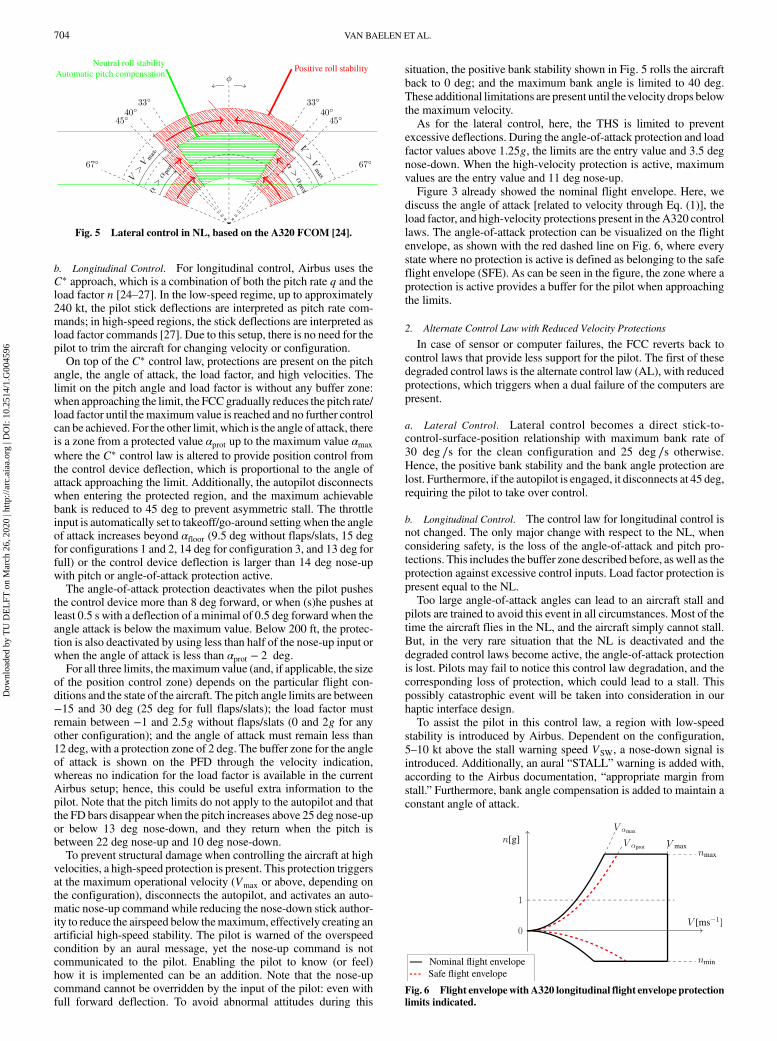
exceeds 45 deg; at which point, the flight director (FD) bars (indica-tion of the guidance by the FCC on the PFD) disappear. Thebars return when the bank angle reduces below 40 deg. To preventexcessive trimmable horizontal stabilizer (THS) deflections due tothemanual or autotrim functionality, the deflection is limited betweenthe value on entering of the protection and 3.5 deg nose-down.Finally, limits for the bank angle depend on the longitudinal protec-tions, which are elaborated on in the following. Avisual summary ofthe lateral protections can be found in Fig. 5 [24].
Table 2 Summary of airbus flight envelope protection
Variable Normal law Alternate law
Bank ϕ THS limited between entry value and 3.5 deg nose-down Autopilot disconnects when ϕ > 45 deg
Autopilot disconnects when ϕ > 45 deg No other protectionsFD bars disappear when ϕ > 45 deg
FD bars return when ϕ < 40 deg
Nominal maximum: 67 degMaximum with αprot active: 45 degMaximum with V > VMO: 40 degNominal protection: positive bank stability to �33 deg
Protection with V > VMO: positive bank stability to 0 deg
Pitch θ No limit for Autopilot ——
Nose-up maximum, flaps 0–3: 30 degNose-up maximum, full flaps: 25 degNose-down maximum: −15 deg
FD bars disappear when θ > 25 deg or θ < −13 deg
FD bars return when θ < 22 deg or θ > −10 deg
High angle of attack α THS limited between entry value and 3.5 deg nose-down ——
Autopilot disconnects when α > αprotPilot input proportional in region: αprot → αmax
Protection deactivates: when 8 deg forward input or 0.5 degforward for 0.5 s when α < αmax
Below 200 ft, protection deactivates when pilot input halfof nose-up input or when α < αprot − 2
When α > αfloor, thrust is set to takeoff/go-arounda
Low velocity V —— At 5–10 KTS above VSWb:
a nose-down command is insertedwith bank angle compensationto keep α constant
An aural “STALL” warning is providedwith appropriate margin from stall
High velocity V THS limited between entry value and 11 deg nose-up When V > Vmax: autopilot disconnectsWhen V > Vmax
c: autopilot disconnects Nose-up command is insertedpilot nose-down authority is reduced and can be overruled by pilotan automatic nose-up command is introduced When V > VMO � 4:command cannot be overruled by pilot an aural “Overspeed” warning sounds
Load factor nz THS limited between entry value and 3.5 deg nose-down when n > 1.25 Equal to normal lawMaximum, clean: 2.5Maximum, with flaps/slats: 2Minimum, clean: −1Minimum, with flaps/slats: 0
aαfloor � 9.5 deg without flaps/slats (15 deg for configurations 1 and 2, 14 deg for configuration 3, and 13 deg for full) or when pilot inputs 14 deg pitch-up with either pitch orangle-of-attack protection active.bSpeed margin according to Airbus documentation: “Based on the aircraft gross weight and slats/flaps configuration.”cAirbus documentation is unclear on the exact activation point: “at/or above Vmax.”
Table 1 Summary of airbus flight control laws
Direction Normal law Alternate law
Lateral 1) Bank rate demand 1) Bank direct stick-to-surface
2) 15 deg ∕s for fulllateral deflection
2) Clean maximumof 30 deg ∕s3) Otherwise, 25 deg ∕s
Longitudinal 1) C� control law Control law equal to NL2) Autotrim for changing speed
or configuration3) Automatic pitch compensation
for ϕ ≤ �33
VAN BAELEN ETAL. 703
Dow
nloa
ded
by T
U D
EL
FT o
n M
arch
26,
202
0 | h
ttp://
arc.
aiaa
.org
| D
OI:
10.
2514
/1.G
0045
96
b. Longitudinal Control. For longitudinal control, Airbus uses theC� approach, which is a combination of both the pitch rate q and theload factor n [24–27]. In the low-speed regime, up to approximately240 kt, the pilot stick deflections are interpreted as pitch rate com-mands; in high-speed regions, the stick deflections are interpreted asload factor commands [27]. Due to this setup, there is no need for thepilot to trim the aircraft for changing velocity or configuration.On top of the C� control law, protections are present on the pitch
angle, the angle of attack, the load factor, and high velocities. Thelimit on the pitch angle and load factor is without any buffer zone:when approaching the limit, the FCCgradually reduces the pitch rate/load factor until the maximum value is reached and no further controlcan be achieved. For the other limit, which is the angle of attack, thereis a zone from a protected value αprot up to the maximum value αmax
where the C� control law is altered to provide position control fromthe control device deflection, which is proportional to the angle ofattack approaching the limit. Additionally, the autopilot disconnectswhen entering the protected region, and the maximum achievablebank is reduced to 45 deg to prevent asymmetric stall. The throttleinput is automatically set to takeoff/go-around setting when the angleof attack increases beyond αfloor (9.5 deg without flaps/slats, 15 degfor configurations 1 and 2, 14 deg for configuration 3, and 13 deg forfull) or the control device deflection is larger than 14 deg nose-upwith pitch or angle-of-attack protection active.The angle-of-attack protection deactivates when the pilot pushes
the control device more than 8 deg forward, or when (s)he pushes atleast 0.5 s with a deflection of a minimal of 0.5 deg forward when theangle attack is below the maximum value. Below 200 ft, the protec-tion is also deactivated by using less than half of the nose-up input orwhen the angle of attack is less than αprot − 2 deg.For all three limits, themaximum value (and, if applicable, the size
of the position control zone) depends on the particular flight con-ditions and the state of the aircraft. The pitch angle limits are between−15 and 30 deg (25 deg for full flaps/slats); the load factor mustremain between −1 and 2.5g without flaps/slats (0 and 2g for anyother configuration); and the angle of attack must remain less than12 deg, with a protection zone of 2 deg. The buffer zone for the angleof attack is shown on the PFD through the velocity indication,whereas no indication for the load factor is available in the currentAirbus setup; hence, this could be useful extra information to thepilot. Note that the pitch limits do not apply to the autopilot and thatthe FD bars disappear when the pitch increases above 25 deg nose-upor below 13 deg nose-down, and they return when the pitch isbetween 22 deg nose-up and 10 deg nose-down.To prevent structural damage when controlling the aircraft at high
velocities, a high-speed protection is present. This protection triggersat the maximum operational velocity (Vmax or above, depending onthe configuration), disconnects the autopilot, and activates an auto-matic nose-up command while reducing the nose-down stick author-ity to reduce the airspeed below themaximum, effectively creating anartificial high-speed stability. The pilot is warned of the overspeedcondition by an aural message, yet the nose-up command is notcommunicated to the pilot. Enabling the pilot to know (or feel)how it is implemented can be an addition. Note that the nose-upcommand cannot be overridden by the input of the pilot: even withfull forward deflection. To avoid abnormal attitudes during this
situation, the positive bank stability shown in Fig. 5 rolls the aircraftback to 0 deg; and the maximum bank angle is limited to 40 deg.These additional limitations are present until thevelocity drops belowthe maximum velocity.As for the lateral control, here, the THS is limited to prevent
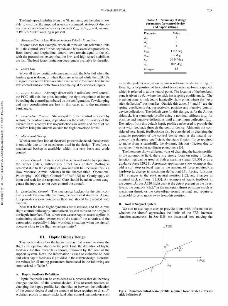
excessive deflections. During the angle-of-attack protection and loadfactor values above 1.25g, the limits are the entry value and 3.5 degnose-down. When the high-velocity protection is active, maximumvalues are the entry value and 11 deg nose-up.Figure 3 already showed the nominal flight envelope. Here, we
discuss the angle of attack [related to velocity through Eq. (1)], theload factor, and high-velocity protections present in the A320 controllaws. The angle-of-attack protection can be visualized on the flightenvelope, as shown with the red dashed line on Fig. 6, where everystate where no protection is active is defined as belonging to the safeflight envelope (SFE). As can be seen in the figure, the zone where aprotection is active provides a buffer for the pilot when approachingthe limits.
2. Alternate Control Law with Reduced Velocity Protections
In case of sensor or computer failures, the FCC reverts back tocontrol laws that provide less support for the pilot. The first of thesedegraded control laws is the alternate control law (AL), with reducedprotections, which triggers when a dual failure of the computers arepresent.
a. Lateral Control. Lateral control becomes a direct stick-to-control-surface-position relationship with maximum bank rate of30 deg ∕s for the clean configuration and 25 deg ∕s otherwise.Hence, the positive bank stability and the bank angle protection arelost. Furthermore, if the autopilot is engaged, it disconnects at 45 deg,requiring the pilot to take over control.
b. Longitudinal Control. The control law for longitudinal control isnot changed. The only major change with respect to the NL, whenconsidering safety, is the loss of the angle-of-attack and pitch pro-tections. This includes the buffer zone described before, aswell as theprotection against excessive control inputs. Load factor protection ispresent equal to the NL.Too large angle-of-attack angles can lead to an aircraft stall and
pilots are trained to avoid this event in all circumstances. Most of thetime the aircraft flies in the NL, and the aircraft simply cannot stall.But, in the very rare situation that the NL is deactivated and thedegraded control laws become active, the angle-of-attack protectionis lost. Pilots may fail to notice this control law degradation, and thecorresponding loss of protection, which could lead to a stall. Thispossibly catastrophic event will be taken into consideration in ourhaptic interface design.To assist the pilot in this control law, a region with low-speed
stability is introduced by Airbus. Dependent on the configuration,5–10 kt above the stall warning speed VSW, a nose-down signal isintroduced. Additionally, an aural “STALL” warning is added with,according to the Airbus documentation, “appropriate margin fromstall.” Furthermore, bank angle compensation is added to maintain aconstant angle of attack.
Fig. 5 Lateral control in NL, based on the A320 FCOM [24].
Fig. 6 Flight envelopewithA320 longitudinal flight envelope protectionlimits indicated.
704 VAN BAELEN ETAL.
Dow
nloa
ded
by T
U D
EL
FT o
n M
arch
26,
202
0 | h
ttp://
arc.
aiaa
.org
| D
OI:
10.
2514
/1.G
0045
96
The high-speed stability from the NL remains, yet the pilot is nowable to overrule the imposed nose-up command. Autopilot discon-nection occurs when the velocity exceedsVmax; atVmax � 4, an aural“OVERSPEED” warning is present.
3. Alternate Control Law Without Reduced Velocity Protections
In some cases (for example, when all three air data reference unitsfail), the control laws further degrade and have even less protections.Both lateral and longitudinal control laws remain equal to the ALwith the protections, except that the low- and high-speed stabilitiesare lost. The load factor limitation does remain available for the pilot.
4. Direct Law
When all three inertial reference units fail, the RAs fail when thelanding gear is down, or when flaps are selected while the LGCIUsdisagree, the control law is reverted evenmore to the direct law. In thislaw, control surface deflections become equal to sidestick inputs.
a. Lateral Control. Although direct stick to roll is low-level control,the FCC still aids the pilot, inputting the right magnitude of inputsby scaling the control gains based on the configuration.Yawdampingand turn coordination are lost in this case, as is the maximumbank angle.
b. Longitudinal Control. Stick-to-pitch direct control is aided byscaling the control gains, depending on the center of gravity of theaircraft. In this control law, no protections are active and the pilot cantherefore bring the aircraft outside the flight envelope limits.
5. Mechanical Backup
When a complete loss of electrical power is detected, the sidestickis unusable due to the transducers used in the design. Therefore, amechanical backup is available, which is a very basic and crudecontrol.
a. Lateral Control. Lateral control is achieved solely by operatingthe rudder pedals, without any direct bank control. Rolling isachieved due to the coupling of yaw and roll but, because this is aslow response, Airbus indicates in the chapter titled “OperationalPhilosophy—020 Flight Controls” of Ref. [28] to “Gently apply aninput and wait for the response.” Care should be taken to not exag-gerate the input as to not over-control the aircraft.
b. Longitudinal Control. The mechanical backup for the pitch con-trol is made by manually trimming the horizontal stabilizer. Again,this provides a slow control method and should be executed withcaution.Now that the basic flight dynamics are discussed, and the Airbus
flight control philosophy summarized, we can move to the design ofour haptic interface. That is, how can we use haptics to assist pilots inmaintaining situation awareness of the state of the aircraft and theautomation, especially in high workload situations when the aircraftoperates close to the flight envelope limits?
III. Haptic Display Design
This section describes the haptic display that is used to show theflight envelope boundaries to the pilot. First, the definition of hapticfeedback for this research is shown, followed by the goal of thesupport system. Next, the information is used to elaborate on howandwhen haptic feedback is provided in the current design. Note thatthe values for all tuning parameters introduced in the following aresummarized in Table 3.
A. Haptic Feedback Definitions
Haptic feedback can be considered as a process that deliberatelychanges the feel of the control device. This research focuses onchanging the haptic profile, i.e., the relation between the deflectionof the control device δ and the amount of force required to do so F.A default profile formany sticks (and other controlmanipulators such
as rudder pedals) is a piecewise linear relation, as shown in Fig. 7.Here, δnp is the position of the control devicewhen no force is applied,which is referred to as the neutral point. The location of the breakoutzone is given by δbr, where the stick has a spring coefficient kbr. Thebreakout zone is included to haptically show pilots where the “zerostick deflection” position lies. Outside this zone, k� and k− are thespring coefficients for, respectively, positive and negative controldevice deflections. The default case for this design, as for the Airbussidestick, is a symmetric profile using a nominal stiffness knom forpositive and negative deflections until a maximum deflection δmax.Deviations from this default haptic profile can be used to provide thepilot with feedback through the control device. Although not con-sidered here, haptic feedback can also be considered by changing thedynamic properties of the control device such as the natural fre-quency, the damping coefficient, the static friction (force requiredto move from a standstill), the dynamic friction (friction due tomovement), or other nonlinear phenomena [3].The literature shows different ways of changing the haptic profile:
in the automotive field, there is a strong focus on using a forcingfunction that can be used as both a warning signal [29,30] or as aguidance force [20,21]. Aerospace applications show examples thatadd a soft stop (a local step in the amount of force required), ahardstop (a change in maximum deflection) [5], forcing functions[31], changes in the stick neutral position [12], and changes innominal stick stiffness [32,33]. An example of haptic feedback inthe current Airbus A320 flight deck is the detent present on the thrustlevers: the controls “click” in the important thrust positions (such asmaximum thrust, or the take-off/go-around setting) and require athreshold force to move away from this position.
B. Goal of Support System
We aim to use haptic cues to provide pilots with information onwhether the aircraft approaches the limits of the FEP: increasesituation awareness. In Sec II.B, we discussed how moving the
Table 3 Summary of designparameters for control device
and haptic settings
Parameter Value
Kα 3Kn 2KVmax
2
knom 1 N∕ degδmax 18 degkpr 50 N∕ degδpr 0.05 deg
τoverspeed 15
Fig. 7 Nominal control device profile: required force exerted F versusstick deflection δ.
VAN BAELEN ETAL. 705
Dow
nloa
ded
by T
U D
EL
FT o
n M
arch
26,
202
0 | h
ttp://
arc.
aiaa
.org
| D
OI:
10.
2514
/1.G
0045
96
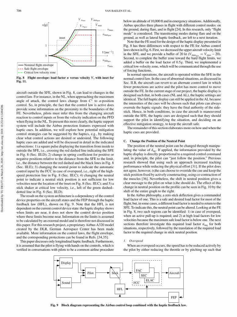
aircraft outside the SFE, shown in Fig. 8, can lead to changes in thecontrol law. For instance, in theNL, when approaching themaximumangle of attack, the control laws change from C� to α-positioncontrol. So, in principle, the fact that the control law is active doesprovide some information on the proximity to the boundaries of theFE. Nevertheless, pilots must infer this from the changing aircraftreaction to control inputs or from the velocity indication on the PFDwhen flying in theNL. To present thismore clearly, the haptic supportsystem will include the Airbus protection features expressed withhaptic cues. In addition, we will explore how potential mitigationcontrol strategies can be suggested by the haptics, e.g., by makingclear what control actions are desired or undesired. The followinghaptic cues are added and will be discussed in detail in the indicatedsubsections: 1) a square pulse displaying the transition from inside tooutside the SFE, i.e., crossing the red dashed line indicating the SFEin Fig. 8 (Sec. III.D); 2) change in spring coefficient for positive ornegative positions relative to the distance from the SFE to the limit,i.e., the distance between the red dashed and the black lines in Fig. 8(Sec. III.E); 3) changing the neutral point to indicate the automaticcontrol input by the FCC in case of overspeed, i.e., right of the high-speed protection line in Fig. 8 (Sec. III.C); 4) changing the neutralpoint to indicate a neutral stick position is not sufficient for lowvelocities near the location of the inset on Fig. 8 (Sec. III.C); and 5) astick shaker at critical low velocity, i.e., left of the green dashed–dotted line in Fig. 8 (Sec. III.D).The result on the system architecture is a dependency of the control
device properties on the aircraft states and the FEP through the hapticfeedback law (HFL), shown on Fig. 9. Note that the HFL is notdependent on the current control device state: the haptic display showswhen limits are near, it does not show the control device positionwhere these limits become near. Information on the limits is assumedto be calculated by an external model and is therefore not discussed inthis paper. For this research project, a proprietary Airbus A320modelcreated by the DLR, German Aerospace Center has been madeavailable. More information on the control laws, the flight envelope,and the corresponding protections can be found in Refs. [34,35].This paper discusses only longitudinal haptic feedback. Furthermore,
it is assumed that the pilot is flying with hands on the controls, which isverified in conversations with pilots to be a common airline procedure
belowanaltitude of 10,000 ft and in emergency situations.Additionally,Airbus specifies three phases in flight with different control modes: onthe ground, during flare, and in flight [24]. In this research, only “flightmode” is considered. The transitioning modes during flare and on theground, as well as lateral haptic feedback, are left to a next iteration.Note that the FE used for the design of the haptic display presented in
Fig. 8 has three differences with respect to the FE for Airbus controllaws shown inFig. 6. First,wedecreased the upper aircraft velocity limitin the SFE, and we provide a buffer of 20 kt (Vmaxprot
� Vmax − 20).Second, to complete the buffer zone toward the hard flight limits, weadded a buffer on the load factor of 0.5g. Third, we implemented acritical low-velocity zone, whichwill be communicated through the useof forcing functions.In normal operations, the aircraft is operated within the SFE in the
normal control law. In the case of abnormal situations, as discussed inSec. II.B, the aircraft can revert to an alternate control law in whichfewer protections are active and the pilot has more control to moveoutside the FE. In the current stage of our project, the haptic display isdesigned such that, in both cases (NL and AL), the haptic settings areidentical. The full haptic display can still be applied in theALbecausethe intensities of the cues will be chosen such that pilots can alwaysoverrule the haptic signals: they have the final authority of the side-stick. Hence, in both conditions, in case the aircraft is maneuveredoutside the SFE, the haptic cues are designed such that they shouldsupport the pilot in identifying the situation, and deciding on aneffective mitigation strategy, to keep the aircraft safe.The remainder of this section elaboratesmore on howandwhen the
haptic cues are provided.
C. Change the Position of the Neutral Point
The position of the neutral point can be changed through manipu-lating the value of δnp. If applied, the information provided by thehaptic display is directly proportional to a required control commandand, in principle, the pilot can “just follow the position.” Previousresearch showed that using such an approach increased trackingperformance while reducing the physical effort [31]. If the pilot doesnot agree, however, (s)he can choose to override the cue and keep thestick position fixed by actively counteracting, using co-contraction ofthe muscles [36]. Nevertheless, the shift in neutral position gives aclear message to the pilot on what (s)he should do. The effect of thischange in neutral position on the profile can be seen in Fig. 10 by theshift of the entire graph to the right.In the Airbus philosophy, a zero stick deflection gives a commanded
load factor of one. This is a safe and desired load factor for most of theflight; but, in some cases, a different load factor is needed to return to theSFE. To indicate this, the neutral point can be altered. Looking at the FEin Fig. 8, two such regions can be identified: 1) in case of overspeed,when an active pull-up is required; and 2) at high load factors for lowvelocities because themaximum safe load factor is below one. The nextsections therefore investigate this required load factor nreq for bothsituations, respectively, followed by the translation of the required loadfactor to the required change in stick neutral position.
1. Overspeed
When an overspeed occurs, the speed has to be reduced actively bythe pilot by either reducing the throttle or by pitching up such that
Display
Sound
Pilot Stick Aircraft
FEP
ELAC
SEC
FAC
FCC
HFL
Fig. 9 Block diagram representing the Airbus control loop combined with the haptic feedback law.
Fig. 8 Flight envelope: load factor n versus velocity V, with inset forFig. 11.
706 VAN BAELEN ETAL.
Dow
nloa
ded
by T
U D
EL
FT o
n M
arch
26,
202
0 | h
ttp://
arc.
aiaa
.org
| D
OI:
10.
2514
/1.G
0045
96
kinetic energy is exchanged for potential energy. In the current state,the Airbus control law will implement a forced nose-up command(see Sec. II.B), which could be translated to a change in the neutralpoint. Nevertheless, the actual implementation of this signal is notknown for this research and is approximated as described in thefollowing. The main reason for this cue is to inform the pilot thatmaintaining the stick at zero deflection does not solve the FE viola-tion, and action needs to be taken. Note that, here, our researchdeviates from the A320 FEP: the nose-up command is not activatedwhen crossing Vmax; it is already activated when crossing Vmaxprot
.For this research, the nose-up command, and therefore the magni-
tude of the neutral point shift, is governed by the change in load factorrequired to bring the positive acceleration to zero. It is determined bystarting from the longitudinal equations of motion [23], where weassume engine thrust to be parallel to the aircraft body:
T cos�α� −D −W sin�γ� � mdV
dt(2)
From all variables in this equation, the pilot can manipulate theaircraft flight path γ through moving the stick. Here, the neutral pointis shifted to obtain a flight path angle such that there is no positiveacceleration: �dV∕dt� � 0. Because the aircraft is accelerating, theleft part of Eq. (2) is not zero and can be rewritten to obtain a steadyflight path:
γsteady � arcsin
�T cos�α� −D
W
�(3)
Thrust and drag cannot be measured directly; their effects can bemeasured through accelerometers, mounted on the aircraft body,which therefore must be rotated to the velocity reference frame:
T cos�α� −D � maxa � m�axb cos�β� cos�α� � aya sin�β�� aza cos�β� sin�α�� (4)
Combining Eq. (3) with Eq. (4) then yields the required change inflight path angle for zero acceleration (γsteady − γ), all expressed inmeasured quantities.As discussed, the sidestick gives load factor commands for
high velocities; therefore, a relation between the change in the flightpath angle and the load factor is also required. The load factor isgoverned by the time derivative of the flight path angle; therefore, atuning factor τoverspeed is chosen, which is a measure of the recoveryspeed:
nreq �V
gtan�γ� � V
g⋅ tan
�γsteady − γ
τoverspeed
�(5)
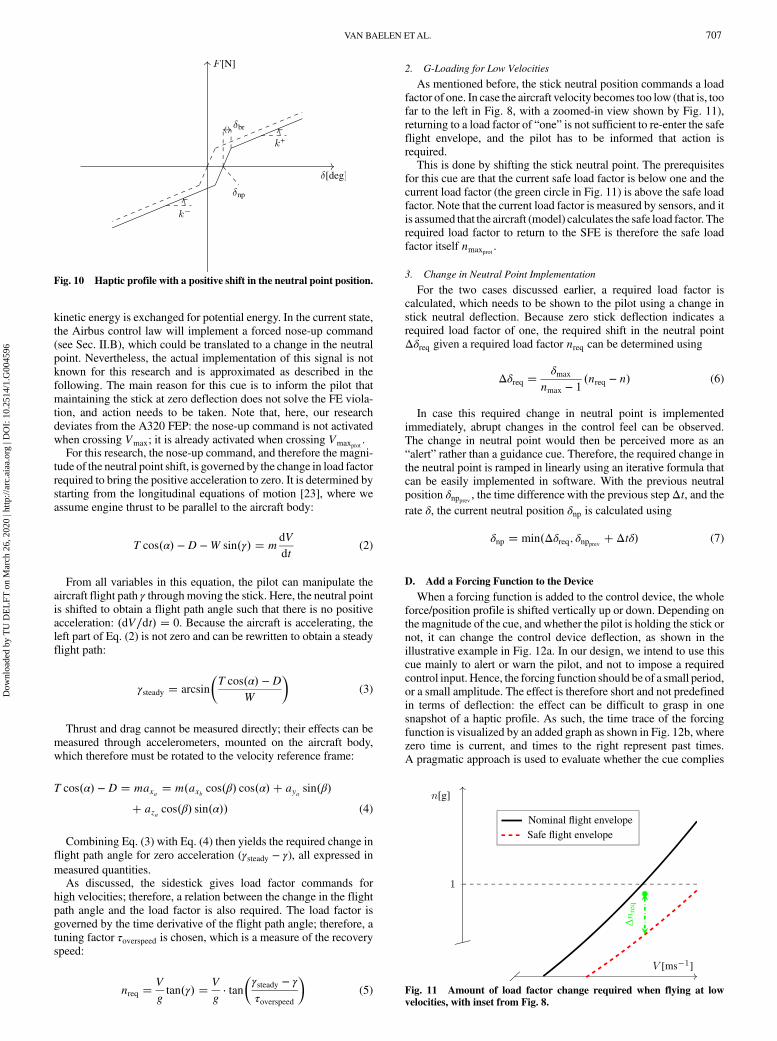
2. G-Loading for Low Velocities
As mentioned before, the stick neutral position commands a loadfactor of one. In case the aircraft velocity becomes too low (that is, toofar to the left in Fig. 8, with a zoomed-in view shown by Fig. 11),returning to a load factor of “one” is not sufficient to re-enter the safeflight envelope, and the pilot has to be informed that action isrequired.This is done by shifting the stick neutral point. The prerequisites
for this cue are that the current safe load factor is below one and thecurrent load factor (the green circle in Fig. 11) is above the safe loadfactor. Note that the current load factor is measured by sensors, and itis assumed that the aircraft (model) calculates the safe load factor. Therequired load factor to return to the SFE is therefore the safe loadfactor itself nmaxprot
.
3. Change in Neutral Point Implementation
For the two cases discussed earlier, a required load factor iscalculated, which needs to be shown to the pilot using a change instick neutral deflection. Because zero stick deflection indicates arequired load factor of one, the required shift in the neutral pointΔδreq given a required load factor nreq can be determined using
Δδreq �δmax
nmax − 1�nreq − n� (6)
In case this required change in neutral point is implementedimmediately, abrupt changes in the control feel can be observed.The change in neutral point would then be perceived more as an“alert” rather than a guidance cue. Therefore, the required change inthe neutral point is ramped in linearly using an iterative formula thatcan be easily implemented in software. With the previous neutralposition δnpprev , the time difference with the previous step Δt, and therate δ, the current neutral position δnp is calculated using
δnp � min�Δδreq; δnpprev � Δtδ� (7)
D. Add a Forcing Function to the Device
When a forcing function is added to the control device, the wholeforce/position profile is shifted vertically up or down. Depending onthe magnitude of the cue, and whether the pilot is holding the stick ornot, it can change the control device deflection, as shown in theillustrative example in Fig. 12a. In our design, we intend to use thiscue mainly to alert or warn the pilot, and not to impose a requiredcontrol input. Hence, the forcing function should be of a small period,or a small amplitude. The effect is therefore short and not predefinedin terms of deflection: the effect can be difficult to grasp in onesnapshot of a haptic profile. As such, the time trace of the forcingfunction is visualized by an added graph as shown in Fig. 12b, wherezero time is current, and times to the right represent past times.A pragmatic approach is used to evaluate whether the cue complies
Fig. 11 Amount of load factor change required when flying at lowvelocities, with inset from Fig. 8.
Fig. 10 Haptic profile with a positive shift in the neutral point position.
VAN BAELEN ETAL. 707
Dow
nloa
ded
by T
U D
EL
FT o
n M
arch
26,
202
0 | h
ttp://
arc.
aiaa
.org
| D
OI:
10.
2514
/1.G
0045
96
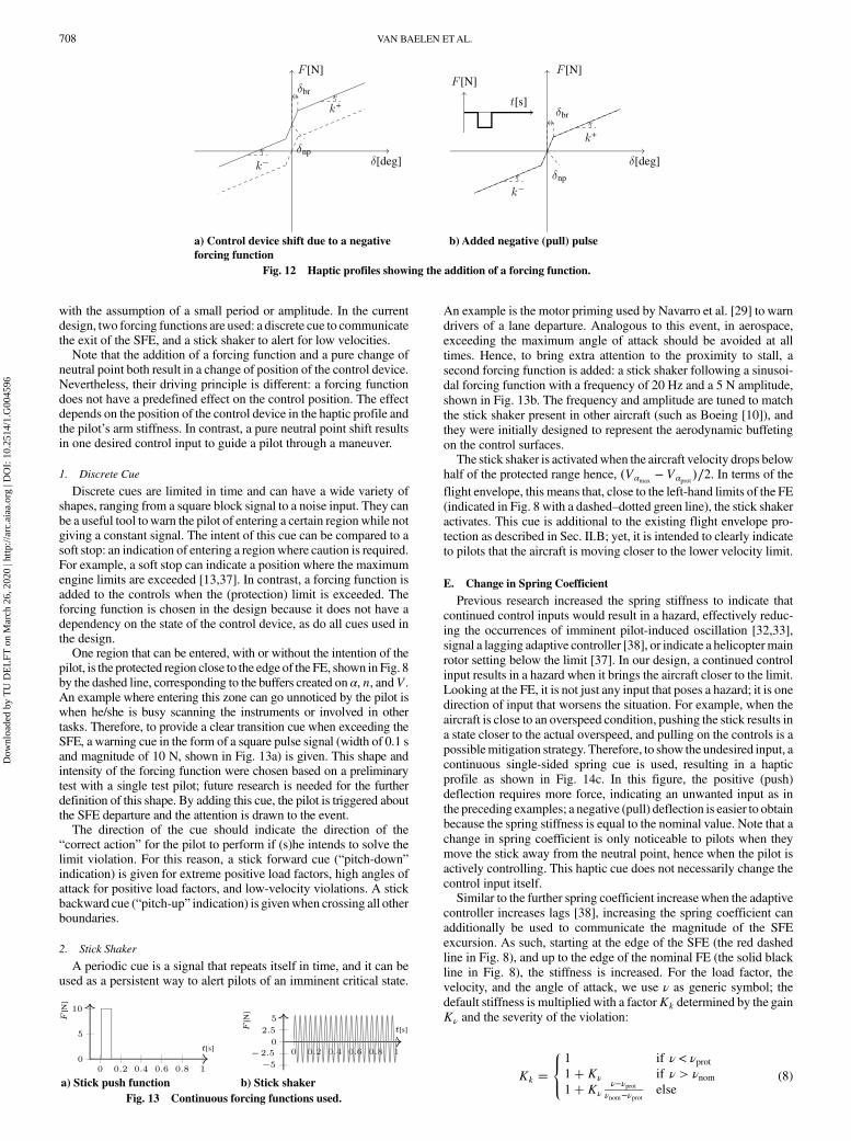
with the assumption of a small period or amplitude. In the currentdesign, two forcing functions are used: a discrete cue to communicatethe exit of the SFE, and a stick shaker to alert for low velocities.Note that the addition of a forcing function and a pure change of
neutral point both result in a change of position of the control device.Nevertheless, their driving principle is different: a forcing functiondoes not have a predefined effect on the control position. The effectdepends on the position of the control device in the haptic profile andthe pilot’s arm stiffness. In contrast, a pure neutral point shift resultsin one desired control input to guide a pilot through a maneuver.
1. Discrete Cue
Discrete cues are limited in time and can have a wide variety ofshapes, ranging from a square block signal to a noise input. They canbe a useful tool towarn the pilot of entering a certain regionwhile notgiving a constant signal. The intent of this cue can be compared to asoft stop: an indication of entering a regionwhere caution is required.For example, a soft stop can indicate a position where the maximumengine limits are exceeded [13,37]. In contrast, a forcing function isadded to the controls when the (protection) limit is exceeded. Theforcing function is chosen in the design because it does not have adependency on the state of the control device, as do all cues used inthe design.One region that can be entered, with or without the intention of the
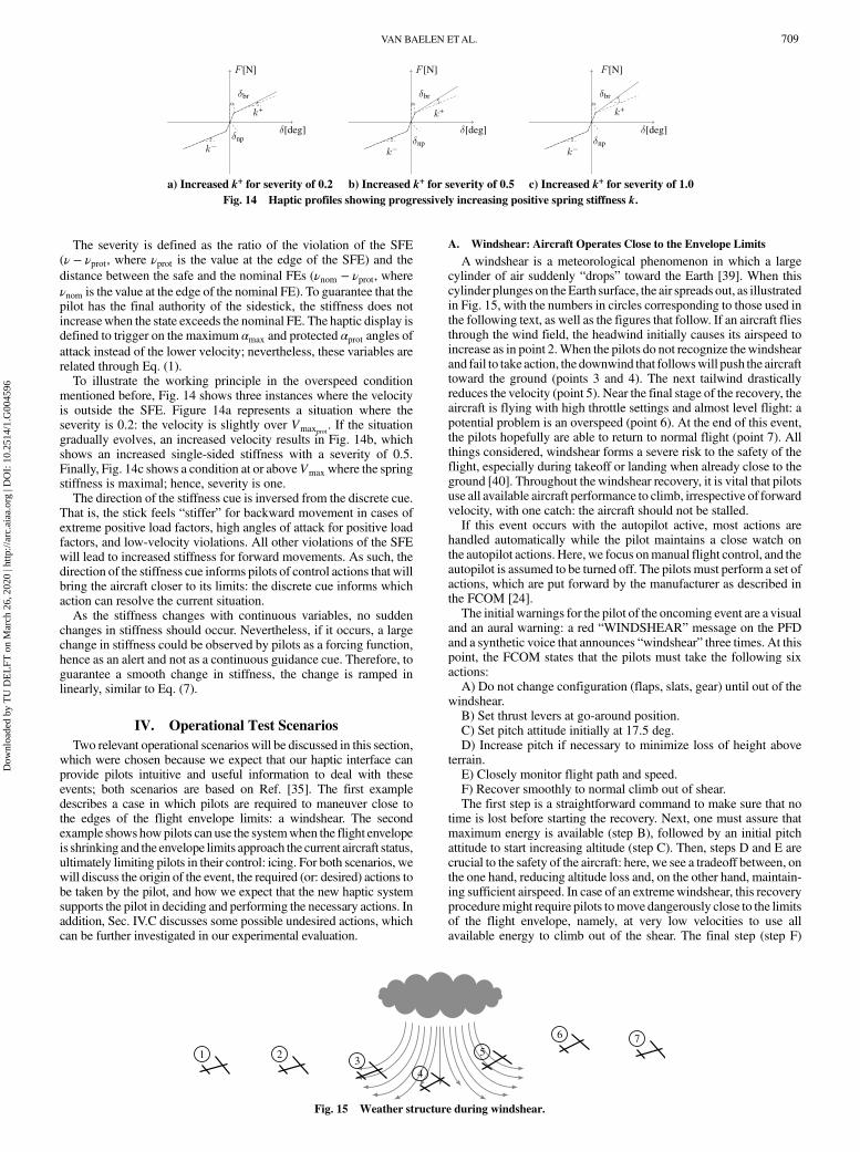
pilot, is the protected region close to the edge of the FE, shown in Fig. 8by the dashed line, corresponding to the buffers created on α, n, andV.An example where entering this zone can go unnoticed by the pilot iswhen he/she is busy scanning the instruments or involved in othertasks. Therefore, to provide a clear transition cue when exceeding theSFE, a warning cue in the form of a square pulse signal (width of 0.1 sand magnitude of 10 N, shown in Fig. 13a) is given. This shape andintensity of the forcing function were chosen based on a preliminarytest with a single test pilot; future research is needed for the furtherdefinition of this shape. By adding this cue, the pilot is triggered aboutthe SFE departure and the attention is drawn to the event.The direction of the cue should indicate the direction of the
“correct action” for the pilot to perform if (s)he intends to solve thelimit violation. For this reason, a stick forward cue (“pitch-down”indication) is given for extreme positive load factors, high angles ofattack for positive load factors, and low-velocity violations. A stickbackward cue (“pitch-up” indication) is givenwhen crossing all otherboundaries.
2. Stick Shaker
A periodic cue is a signal that repeats itself in time, and it can beused as a persistent way to alert pilots of an imminent critical state.
An example is the motor priming used by Navarro et al. [29] to warndrivers of a lane departure. Analogous to this event, in aerospace,exceeding the maximum angle of attack should be avoided at alltimes. Hence, to bring extra attention to the proximity to stall, asecond forcing function is added: a stick shaker following a sinusoi-dal forcing function with a frequency of 20 Hz and a 5 N amplitude,shown in Fig. 13b. The frequency and amplitude are tuned to matchthe stick shaker present in other aircraft (such as Boeing [10]), andthey were initially designed to represent the aerodynamic buffetingon the control surfaces.The stick shaker is activatedwhen the aircraft velocity drops below
half of the protected range hence, �Vαmax− Vαprot�∕2. In terms of the
flight envelope, this means that, close to the left-hand limits of the FE(indicated in Fig. 8 with a dashed–dotted green line), the stick shakeractivates. This cue is additional to the existing flight envelope pro-tection as described in Sec. II.B; yet, it is intended to clearly indicateto pilots that the aircraft is moving closer to the lower velocity limit.
E. Change in Spring Coefficient
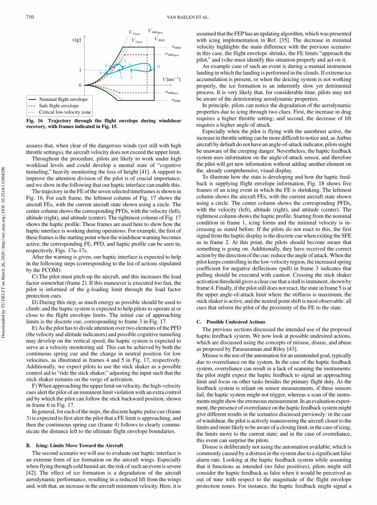
Previous research increased the spring stiffness to indicate thatcontinued control inputs would result in a hazard, effectively reduc-ing the occurrences of imminent pilot-induced oscillation [32,33],signal a lagging adaptive controller [38], or indicate a helicoptermainrotor setting below the limit [37]. In our design, a continued controlinput results in a hazard when it brings the aircraft closer to the limit.Looking at the FE, it is not just any input that poses a hazard; it is onedirection of input that worsens the situation. For example, when theaircraft is close to an overspeed condition, pushing the stick results ina state closer to the actual overspeed, and pulling on the controls is apossiblemitigation strategy. Therefore, to show the undesired input, acontinuous single-sided spring cue is used, resulting in a hapticprofile as shown in Fig. 14c. In this figure, the positive (push)deflection requires more force, indicating an unwanted input as inthe preceding examples; a negative (pull) deflection is easier to obtainbecause the spring stiffness is equal to the nominal value. Note that achange in spring coefficient is only noticeable to pilots when theymove the stick away from the neutral point, hence when the pilot isactively controlling. This haptic cue does not necessarily change thecontrol input itself.Similar to the further spring coefficient increasewhen the adaptive
controller increases lags [38], increasing the spring coefficient canadditionally be used to communicate the magnitude of the SFEexcursion. As such, starting at the edge of the SFE (the red dashedline in Fig. 8), and up to the edge of the nominal FE (the solid blackline in Fig. 8), the stiffness is increased. For the load factor, thevelocity, and the angle of attack, we use ν as generic symbol; thedefault stiffness is multiplied with a factorKk determined by the gainKν and the severity of the violation:
Kk �8<:1 if ν < νprot1� Kν if ν > νnom1� Kν
ν−νprotνnom−νprot
else(8)
a) Control device shift due to a negativeforcing function
b) Added negative (pull) pulse
Fig. 12 Haptic profiles showing the addition of a forcing function.
a) Stick push function b) Stick shakerFig. 13 Continuous forcing functions used.
708 VAN BAELEN ETAL.
Dow
nloa
ded
by T
U D
EL
FT o
n M
arch
26,
202
0 | h
ttp://
arc.
aiaa
.org
| D
OI:
10.
2514
/1.G
0045
96
The severity is defined as the ratio of the violation of the SFE(ν − νprot, where νprot is the value at the edge of the SFE) and thedistance between the safe and the nominal FEs (νnom − νprot, whereνnom is the value at the edge of the nominal FE). To guarantee that thepilot has the final authority of the sidestick, the stiffness does notincreasewhen the state exceeds the nominal FE. The haptic display isdefined to trigger on the maximum αmax and protected αprot angles ofattack instead of the lower velocity; nevertheless, these variables arerelated through Eq. (1).To illustrate the working principle in the overspeed condition
mentioned before, Fig. 14 shows three instances where the velocityis outside the SFE. Figure 14a represents a situation where theseverity is 0.2: the velocity is slightly over Vmaxprot
. If the situationgradually evolves, an increased velocity results in Fig. 14b, whichshows an increased single-sided stiffness with a severity of 0.5.Finally, Fig. 14c shows a condition at or aboveVmax where the springstiffness is maximal; hence, severity is one.The direction of the stiffness cue is inversed from the discrete cue.
That is, the stick feels “stiffer” for backward movement in cases ofextreme positive load factors, high angles of attack for positive loadfactors, and low-velocity violations. All other violations of the SFEwill lead to increased stiffness for forward movements. As such, thedirection of the stiffness cue informs pilots of control actions that willbring the aircraft closer to its limits: the discrete cue informs whichaction can resolve the current situation.As the stiffness changes with continuous variables, no sudden
changes in stiffness should occur. Nevertheless, if it occurs, a largechange in stiffness could be observed by pilots as a forcing function,hence as an alert and not as a continuous guidance cue. Therefore, toguarantee a smooth change in stiffness, the change is ramped inlinearly, similar to Eq. (7).
IV. Operational Test Scenarios
Two relevant operational scenarios will be discussed in this section,which were chosen because we expect that our haptic interface canprovide pilots intuitive and useful information to deal with theseevents; both scenarios are based on Ref. [35]. The first exampledescribes a case in which pilots are required to maneuver close tothe edges of the flight envelope limits: a windshear. The secondexample shows howpilots can use the systemwhen the flight envelopeis shrinking and the envelope limits approach the current aircraft status,ultimately limiting pilots in their control: icing. For both scenarios, wewill discuss the origin of the event, the required (or: desired) actions tobe taken by the pilot, and how we expect that the new haptic systemsupports the pilot in deciding and performing the necessary actions. Inaddition, Sec. IV.C discusses some possible undesired actions, whichcan be further investigated in our experimental evaluation.
A. Windshear: Aircraft Operates Close to the Envelope Limits
A windshear is a meteorological phenomenon in which a largecylinder of air suddenly “drops” toward the Earth [39]. When thiscylinder plunges on theEarth surface, the air spreads out, as illustratedin Fig. 15, with the numbers in circles corresponding to those used inthe following text, as well as the figures that follow. If an aircraft fliesthrough the wind field, the headwind initially causes its airspeed toincrease as in point 2.When the pilots do not recognize thewindshearand fail to take action, the downwind that followswill push the aircrafttoward the ground (points 3 and 4). The next tailwind drasticallyreduces the velocity (point 5). Near the final stage of the recovery, theaircraft is flying with high throttle settings and almost level flight: apotential problem is an overspeed (point 6). At the end of this event,the pilots hopefully are able to return to normal flight (point 7). Allthings considered, windshear forms a severe risk to the safety of theflight, especially during takeoff or landing when already close to theground [40]. Throughout thewindshear recovery, it is vital that pilotsuse all available aircraft performance to climb, irrespective of forwardvelocity, with one catch: the aircraft should not be stalled.If this event occurs with the autopilot active, most actions are
handled automatically while the pilot maintains a close watch onthe autopilot actions. Here, we focus onmanual flight control, and theautopilot is assumed to be turned off. The pilots must perform a set ofactions, which are put forward by the manufacturer as described inthe FCOM [24].The initial warnings for the pilot of the oncoming event are a visual
and an aural warning: a red “WINDSHEAR” message on the PFDand a synthetic voice that announces “windshear” three times. At thispoint, the FCOM states that the pilots must take the following sixactions:A) Do not change configuration (flaps, slats, gear) until out of the
windshear.B) Set thrust levers at go-around position.C) Set pitch attitude initially at 17.5 deg.D) Increase pitch if necessary to minimize loss of height above
terrain.E) Closely monitor flight path and speed.F) Recover smoothly to normal climb out of shear.The first step is a straightforward command to make sure that no
time is lost before starting the recovery. Next, one must assure thatmaximum energy is available (step B), followed by an initial pitchattitude to start increasing altitude (step C). Then, steps D and E arecrucial to the safety of the aircraft: here, we see a tradeoff between, onthe one hand, reducing altitude loss and, on the other hand, maintain-ing sufficient airspeed. In case of an extremewindshear, this recoveryproceduremight require pilots tomove dangerously close to the limitsof the flight envelope, namely, at very low velocities to use allavailable energy to climb out of the shear. The final step (step F)
a) Increased k+ for severity of 0.2 b) Increased k+ for severity of 0.5 c) Increased k+ for severity of 1.0Fig. 14 Haptic profiles showing progressively increasing positive spring stiffness k.
1 23
4
5
6 7
Fig. 15 Weather structure during windshear.
VAN BAELEN ETAL. 709
Dow
nloa
ded
by T
U D
EL
FT o
n M
arch
26,
202
0 | h
ttp://
arc.
aiaa
.org
| D
OI:
10.
2514
/1.G
0045
96
assures that, when clear of the dangerous winds (yet still with highthrottle settings), the aircraft velocity does not exceed the upper limit.Throughout the procedure, pilots are likely to work under high
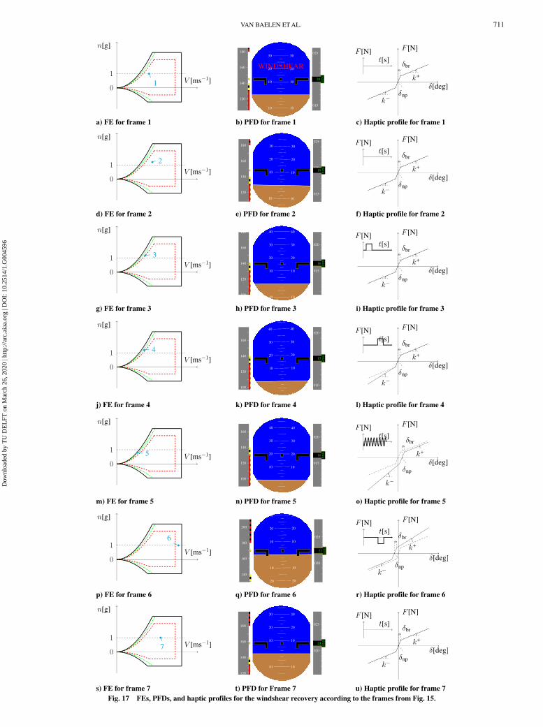
workload levels and could develop a mental state of “cognitivetunneling,” heavily monitoring the loss of height [41]. A support toimprove the attention division of the pilot is of crucial importance,andwe show in the following that our haptic interface can enable this.The trajectory in the FEof the seven selected timeframes is shown in
Fig. 16. For each frame, the leftmost column of Fig. 17 shows theaircraft FEs, with the current aircraft state shown using a circle. Thecenter column shows the corresponding PFDs, with the velocity (left),altitude (right), and attitude (center). The rightmost column of Fig. 17shows the haptic profile. These frames are used here to show how thehaptic interface is working during operations. For example, the first ofthese frames is the starting pointwhen thewindshearwarning becomesactive; the corresponding FE, PFD, and haptic profile can be seen in,respectively, Figs. 17a–17c.After the warning is given, our haptic interface is expected to help
in the following steps (corresponding to the list of actions stipulatedby the FCOM):C) The pilot must pitch-up the aircraft, and this increases the load
factor somewhat (frame 2). If this maneuver is executed too fast, thepilot is informed of the g-loading limit through the load factorprotection cues.D) During this step, as much energy as possible should be used to
climb; and the haptic system is expected to help pilots to operate at orclose to the flight envelope limits. The initial cue of approachinglimits is the discrete cue, corresponding to frame 3 in Fig. 17.E)As the pilot has to divide attention over two elements of the PFD
(the velocity and altitude indicators) and possible cognitive tunnelingmay develop on the vertical speed, the haptic system is expected toserve as a velocity monitoring aid. This can be achieved by both thecontinuous spring cue and the change in neutral position for lowvelocities, as illustrated in frames 4 and 5 in Fig. 17, respectively.Additionally, we expect pilots to use the stick shaker as a possiblecontrol aid to “ride the stick shaker,” adjusting the input such that thestick shaker remains on the verge of activation.F)When approaching the upper limit onvelocity, the high-velocity
cues alert the pilot of an imminent limit violationwith an extra controlaid by which the pilot can follow the stick backward position, shownin frame 6 in Fig. 17.In general, for each of the steps, the discrete haptic pulse cue (frame
3) is expected to first alert the pilot that a FE limit is approaching, andthen the continuous spring cue (frame 4) follows to clearly commu-nicate the distance left to the ultimate flight envelope boundaries.
B. Icing: Limits Move Toward the Aircraft
The second scenario we will use to evaluate our haptic interface isan extreme form of ice formation on the aircraft wings. Especiallywhen flying through cold humid air, the risk of such an event is severe[42]. The effect of ice formation is a degradation of the aircraftaerodynamic performance, resulting in a reduced lift from the wingsand, with that, an increase in the aircraft minimum velocity. Here, it is
assumed that the FEPhas an updating algorithm,whichwas presentedwith icing implementation in Ref. [35]. The decrease in minimalvelocity highlights the main difference with the previous scenario:in this case, the flight envelope shrinks, the FE limits “approach thepilot,” and (s)he must identify this situation properly and act on it.An example case of such an event is during a manual instrument
landing inwhich the landing is performed in the clouds. If extreme iceaccumulation is present, or when the deicing system is not workingproperly, the ice formation is an inherently slow yet detrimentalprocess. It is very likely that, for considerable time, pilots may notbe aware of the deteriorating aerodynamic properties.In principle, pilots can notice the degradation of the aerodynamic
properties due to icing through two clues. First, the increase in dragrequires a higher throttle setting; and second, the decrease of liftrequires a higher angle of attack.Especially when the pilot is flying with the autothrust active, the
increase in throttle setting can bemore difficult to notice and, asAirbusaircraft by default do not have an angle-of-attack indicator, pilotsmightbe unaware of the creeping danger. Nevertheless, the haptic feedbacksystem uses information on the angle-of-attack sensor, and thereforethe pilot will get new information without adding another element onthe, already comprehensive, visual display.To illustrate how the state is developing and how the haptic feed-
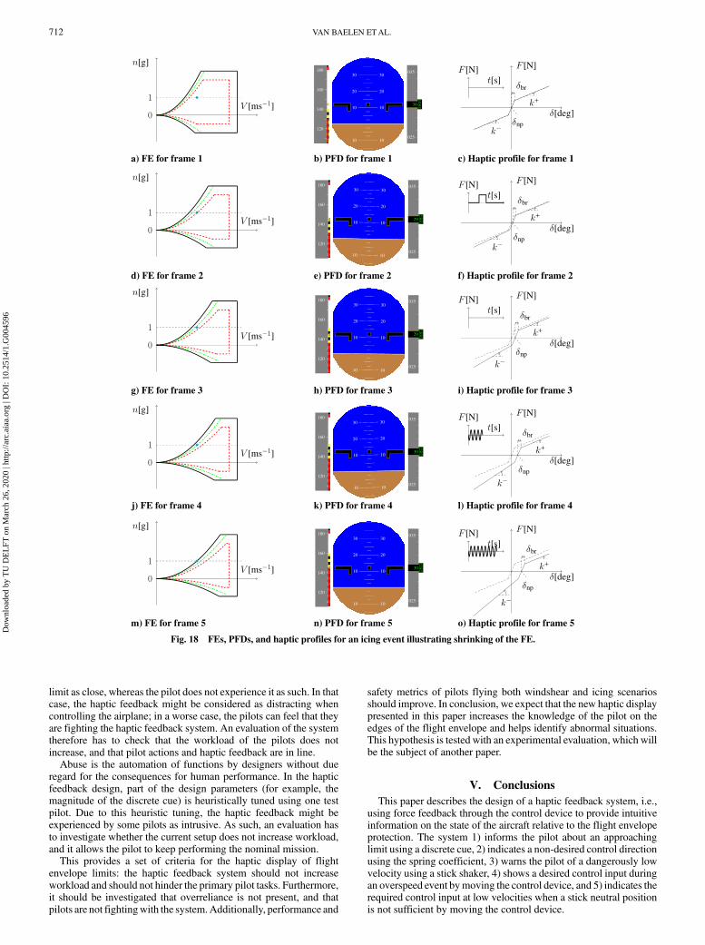
back is supplying flight envelope information, Fig. 18 shows fiveframes of an icing event in which the FE is shrinking. The leftmostcolumn shows the aircraft FEs, with the current aircraft state shownusing a circle. The center column shows the corresponding PFDs,with the velocity (left), altitude (right), and attitude (center). Therightmost column shows the haptic profile. Starting from the nominalcondition in frame 1, icing forms and the minimal velocity is in-creasing as stated before. If the pilots do not react to this, the firstsignal from the haptic display is the discrete cuewhen exiting the SFEas in frame 2. At this point, the pilots should become aware thatsomething is going on. Additionally, they have received the correctaction by the direction of the cue: reduce the angle of attack.When thepilot keeps controlling in the low-velocity region, the increased springcoefficient for negative deflections (pull) in frame 3 indicates thatpulling should be executed with caution. Crossing the stick shakeractivation thresholdgives a clear cue that a stall is imminent, shownbyframe 4. Finally, if the pilot still does not react, the state in frame 5 is atthe upper angle-of-attack limit where the stiffness is maximum, thestick shaker is active, and the neutral point shift ismost observable: allcues that inform the pilot of the proximity of the FE to the state.
C. Possible Undesired Actions
The previous sections discussed the intended use of the proposedhaptic feedback system. We now look at possible undesired actions,which are discussed using the concepts of misuse, disuse, and abuseas proposed by Parasuraman and Riley [43].Misuse is the use of the automation for an unintended goal, typically
due to overreliance on the system. In the case of the haptic feedbacksystem, overreliance can result in a lack of scanning the instruments:the pilot might expect the haptic feedback to signal an approachinglimit and focus on other tasks besides the primary flight duty. As thefeedback system is reliant on sensor measurements, if these sensorsfail, the haptic system might not trigger, whereas a scan of the instru-mentsmight show the erroneousmeasurement. In an evaluation experi-ment, the presenceof overreliance on the haptic feedback systemmightgive different results in the scenarios discussed previously: in the caseofwindshear, the pilot is activelymaneuvering the aircraft closer to thelimits andmore likely to be aware of a closing limit; in the case of icing,the limits move to the current state; and in the case of overreliance,this event can surprise the pilots.Disuse is deliberately not using the automation available, which is
commonly caused by a distrust in the system due to a significant falsealarm rate. Looking at the haptic feedback system while assumingthat it functions as intended (no false positives), pilots might stillconsider the haptic feedback as false when it would be perceived asout of tune with respect to the magnitude of the flight envelopeprotection zones. For instance, the haptic feedback might signal a
Fig. 16 Trajectory through the flight envelope during windshearrecovery, with frames indicated in Fig. 15.
710 VAN BAELEN ETAL.
Dow
nloa
ded
by T
U D
EL
FT o
n M
arch
26,
202
0 | h
ttp://
arc.
aiaa
.org
| D
OI:
10.
2514
/1.G
0045
96
a) FE for frame 1
d) FE for frame 2
g) FE for frame 3
j) FE for frame 4
m) FE for frame 5
p) FE for frame 6
s) FE for frame 7 t) PFD for Frame 7 u) Haptic profile for frame 7
q) PFD for frame 6 r) Haptic profile for frame 6
n) PFD for frame 5 o) Haptic profile for frame 5
k) PFD for frame 4 l) Haptic profile for frame 4
h) PFD for frame 3 i) Haptic profile for frame 3
e) PFD for frame 2 f) Haptic profile for frame 2
b) PFD for frame 1 c) Haptic profile for frame 1
Fig. 17 FEs, PFDs, and haptic profiles for the windshear recovery according to the frames from Fig. 15.
VAN BAELEN ETAL. 711
Dow
nloa
ded
by T
U D
EL
FT o
n M
arch
26,
202
0 | h
ttp://
arc.
aiaa
.org
| D
OI:
10.
2514
/1.G
0045
96
limit as close, whereas the pilot does not experience it as such. In thatcase, the haptic feedback might be considered as distracting whencontrolling the airplane; in a worse case, the pilots can feel that theyare fighting the haptic feedback system. An evaluation of the systemtherefore has to check that the workload of the pilots does notincrease, and that pilot actions and haptic feedback are in line.Abuse is the automation of functions by designers without due
regard for the consequences for human performance. In the hapticfeedback design, part of the design parameters (for example, themagnitude of the discrete cue) is heuristically tuned using one testpilot. Due to this heuristic tuning, the haptic feedback might beexperienced by some pilots as intrusive. As such, an evaluation hasto investigate whether the current setup does not increase workload,and it allows the pilot to keep performing the nominal mission.This provides a set of criteria for the haptic display of flight
envelope limits: the haptic feedback system should not increaseworkload and should not hinder the primary pilot tasks. Furthermore,it should be investigated that overreliance is not present, and thatpilots are not fightingwith the system.Additionally, performance and
safety metrics of pilots flying both windshear and icing scenariosshould improve. In conclusion, we expect that the new haptic displaypresented in this paper increases the knowledge of the pilot on theedges of the flight envelope and helps identify abnormal situations.This hypothesis is tested with an experimental evaluation, which willbe the subject of another paper.
V. Conclusions
This paper describes the design of a haptic feedback system, i.e.,using force feedback through the control device to provide intuitiveinformation on the state of the aircraft relative to the flight envelopeprotection. The system 1) informs the pilot about an approachinglimit using a discrete cue, 2) indicates a non-desired control directionusing the spring coefficient, 3) warns the pilot of a dangerously lowvelocity using a stick shaker, 4) shows a desired control input duringan overspeed event bymoving the control device, and 5) indicates therequired control input at low velocities when a stick neutral positionis not sufficient by moving the control device.
a) FE for frame 1 b) PFD for frame 1 c) Haptic profile for frame 1
d) FE for frame 2 e) PFD for frame 2 f) Haptic profile for frame 2
g) FE for frame 3 h) PFD for frame 3 i) Haptic profile for frame 3
j) FE for frame 4 k) PFD for frame 4 l) Haptic profile for frame 4
m) FE for frame 5 n) PFD for frame 5 o) Haptic profile for frame 5
Fig. 18 FEs, PFDs, and haptic profiles for an icing event illustrating shrinking of the FE.
712 VAN BAELEN ETAL.
Dow
nloa
ded
by T
U D
EL
FT o
n M
arch
26,
202
0 | h
ttp://
arc.
aiaa
.org
| D
OI:
10.
2514
/1.G
0045
96
References
[1] Harris, D., Human Factors for Civil Flight Deck Design, AshgatePublishing Ltd., Cornwall, England, U.K., 2004, pp. 69–102,141–155, Chaps. 4, 6.
[2] van Erp, J. B. F., Kyung, K., Kassner, S., Carter, J., Brewster, S., Weber,G., and Andrew, I., “Setting the Standards for Haptic and TactileInteractions: ISO’s Work,” Haptics: Generating and Perceiving Tan-
gible Sensations, edited by A. M. L. Kappers, J. B. F. van Erp, W. M.Bergmann Tiest, and F. C. T. van der Helm, Springer, Berlin, 2010,pp. 353–358.https://doi.org/10.1007/978-3-642-14075-4_52
[3] “Ergonomics of Human-System Interaction—Part 910: Frameworkfor Tactile and Haptic Interaction (ISO),” International Organizationfor Standardization, STD “9241-910:2011,” Brussels, July 2011.
[4] Corps, S. G., “Airbus A320 Side Stick and Fly by Wire—An Update,”Proceedings of the Aerospace Technology Conference and Exposition,SAE International TP 861801, Warrendale, PA, 1986.https://doi.org/10.4271/861801
[5] Hegg, J. W., Smith, M. P., and Yount, L., “Sidestick Controllersfor Advanced Aircraft Cockpits,” Proceedings of the IEEE/AIAA 11th
Digital Avionics Systems Conference, IEEE Publ., Piscataway, NJ,1992, pp. 491–499.https://doi.org/10.1109/DASC.1992.282112
[6] Warwick, G., “Active Sidestick Controls Make Commercial Debut,”Aviation Week and Space Technology, 2015, https://aviationweek.com/aerospace/active-sidestick-controls-make-commercial-debut [accessed14 Nov. 2017].
[7] “Final Report on the Accident on 1st June 2009 to the Airbus A330-203Registered F-GZCP Operated by Air France Flight AF 447 Rio deJaneiro - Paris,” Bureau d’Enquêtes et d’Analyses pour la Sécurité del’Aviation Civile, TR f-cp090601en, Le Bourget Cedex, France, June2009 (in English).
[8] Gibson, J. C., and Hess, R. A., Stick and Feel System Design, AGARD,Neuilly-Sur-Seine, France, 1997, pp. 34–36, Chap. 1.4.
[9] Cook, R. H., “An Automatic Stall Prevention Control for SupersonicFighter Aircraft,” Journal of Aircraft, Vol. 2, No. 3, 1965, pp. 171–175.https://doi.org/10.2514/3.43636
[10] “777 Flight Crew Training Manual,” The Boeing Company TR FCT777, Chicago, Illinois, 2008.
[11] Schmidt-Skipiol, F. J. J., andHecker, P., “Tactile Feedback and SituationAwareness,” 15th AIAA Aviation Technology, Integration, and Oper-
ations Conference, AIAA Paper 2015-2905, 2015.https://doi.org/10.2514/6.2015-2905
[12] Stepanyan, V., Krishnakumar, K., Dorais, G., Reardon, S., Barlow, J.,Lampton, A., andHardy, G., “Loss-of-ControlMitigation via PredictiveCuing,” Journal of Guidance, Control, and Dynamics, Vol. 40, No. 4,2017, pp. 831–846.https://doi.org/10.2514/1.G001731
[13] Whalley, M. S., Hindson, W., Thiers, G., and Rutkowski, M., “A Com-parison of Active Sidestick and Conventional Inceptors for HelicopterFlight Envelope Tactile Cueing,” Proceedings of the 56th American
Helicopter Society Forum, AHS, Alexandria, VA, 2000, p. 24, https://ntrs.nasa.gov/search.jsp?R=20000092066 [retrieved 27 July 2018].
[14] Sahasrabudhe,V.,Horn, J. F., Sahani,N., Faynberg,A., andSpaulding,R.,“Simulation Investigation of a Comprehensive Collective-Axis TactileCueing System,” Journal of the American Helicopter Society, Vol. 51,No. 3, 2006, pp. 215–224.https://doi.org/10.4050/1.3092883
[15] von Grünhagen, W., Müllhäuser, M., Abildgaard, M., and Lantzsch, R.,“Active Inceptors in FHS for Pilot Assistance Systems,” Proceedings ofthe 36th European Rotorcraft Forum, Paris, France, 2010, Paper 134,http://doi.org/20.500.11881/935.
[16] Fellah, K., andHuiatni,M., “Tactile DisplayDesign for Flight EnvelopeProtection and Situational Awareness,” IEEE Transactions on Haptics,Vol. 12, No. 1, 2019, pp. 87–98.https://doi.org/10.1109/TOH.2018.2865302
[17] Ackerman, K. A., Talleur, D. A., Carbonari, R. S., Xargay, E., Seefeldt,B.D.,Kirlik,A.,Hovakimyan,N., andTrujillo,A.C.,“AutomationSituationAwareness Display for a Flight Envelope Protection System,” Journal of
Guidance, Control, and Dynamics, Vol. 40, No. 4, 2017, pp. 964–980.https://doi.org/10.2514/1.G000338
[18] de Stigter, S., Mulder, M., and van Paassen, M. M., “Design andEvaluation of a Haptic Flight Director,” Journal of Guidance, Control,and Dynamics, Vol. 30, No. 1, 2007, pp. 35–46.https://doi.org/10.2514/1.20593
[19] Smisek, J., Sunil, E., van Paassen, M. M., Abbink, D. A., and Mulder,M., “Neuromuscular-System-Based Tuning of a Haptic SharedControl Interface for UAV Teleoperation,” IEEE Transactions on
Human-Machine Systems, Vol. 47, No. 4, 2017, pp. 449–461.https://doi.org/10.1109/THMS.6221037
[20] Mulder, M., Pauwelussen, J. J., van Paassen, M. M., Mulder, M., andAbbink, D. A., “Active Deceleration Support in Car Following,” IEEETransactions on Systems, Man, and Cybernetics Part A:Systems and
Humans, Vol. 40, No. 6, 2010, pp. 1271–1284.https://doi.org/10.1109/TSMCA.2010.2044998
[21] Petermeijer, S. M., Abbink, D. A., Mulder, M., and De Winter, J. C. F.,“The Effect of Haptic Support Systems on Driver Performance: ALiterature Survey,” IEEE Transactions on Haptics, Vol. 8, No. 4,2015, pp. 467–479.https://doi.org/10.1109/TOH.2015.2437871
[22] Ellerbroek, J., Rodriguez Martin, M. J. M., Lombaerts, T. J. J., vanPaassen, M. M., and Mulder, M., “Design and Evaluation of a FlightEnvelope Protection Haptic Feedback System,” IFAC-PapersOnLine,Vol. 49, No. 19, 2016, pp. 171–176.https://doi.org/10.1016/j.ifacol.2016.10.481
[23] Ruijgrok, G. J. J., Elements of Airplane Performance, 2nd ed., VSSD,Delft, The Netherlands, 2009, pp. 1–23, 51–62, Chaps. 1, 3.
[24] “A319/A320/A321 Flight CrewOperatingManual,”Airbus TR 36, 2003.[25] Chatrenet, D., “Les Qualités de Vol des Avions de Transport Civil à
Commandes de Vol Électriques,” Active Control Technology: Applica-tions and Lesson Learned, AGARD CP-560, Neuilly-Sur-Seine,France, 1995, p. 5.
[26] Favre, C., “Fly-by-Wire for CommercialAircraft: TheAirbus Experience,”International Journal of Control, Vol. 59, No. 1, 1994, pp. 139–157.https://doi.org/10.1080/00207179408923072
[27] Niedermeier, D., and Lambregts, A. A., “Fly-by-Wire AugmentedManual Control—Basic Design Considerations,” 28th International
Congress of the Aeronautical Sciences, Vol. 100, ICAS, Edinburgh,U.K., 2012, pp. 1–14, http://www.icas.org/ICAS_ARCHIVE/ICAS2012/ [accessed 16 Dec. 2019].
[28] “A318/A319/A320/A321 Flight Crew Training Manual,” Tech. Rept.,The Airbus Company, 2015.
[29] Navarro, J., Mars, F., Forzy, J.-F., El-Jaafari, M., and Hoc, J.-M.,“Objective and Subjective Evaluation of Motor Priming and WarningSystems Applied to Lateral Control Assistance,” Accident Analysis andPrevention, Vol. 42, No. 3, 2010, pp. 904–912.https://doi.org/10.1016/j.aap.2009.07.008
[30] Huang, Z., Wu, Y., and Liu, J., “Research on Effects of Pattern,Amplitude and Frequency of Pulse Steering Torque Warnings for LaneDeparture,” Transportation Research, Part F, Vol. 31, May 2015,pp. 67–76.https://doi.org/10.1016/j.trf.2015.03.008.
[31] Olivari, M., Nieuwenhuizen, F., Bülthoff, H., and Pollini, L., “Pilot Adap-tation to Different Classes of Haptic Aids in Tracking Tasks,” Journal ofGuidance, Control, and Dynamics, Vol. 37, No. 6, 2014, pp. 1741–1753.https://doi.org/10.2514/1.G000534
[32] Jeram, G. J., and Prasad, J. V. R., “Tactile Avoidance Cueing for PilotInduced Oscillation,” AIAA Atmospheric Flight Mechanics Conference
and Exhibit, AIAA Paper 2003-5311, 2003.https://doi.org/10.2514/6.2003-5311
[33] Klyde, D. H., andMcRuer, D. T., “Smart-Cue and Smart-Gain ConceptsDevelopment to Alleviate Loss of Control,” Journal of Guidance,
Control, and Dynamics, Vol. 32, No. 5, 2009, pp. 1409–1417.https://doi.org/10.2514/1.43156
[34] Lombaerts, T. J. J., and Looye, G. H. N., “Design and Flight Testing ofNonlinear Autoflight Control Laws,” AIAA Guidance, Navigation, and
Control Conference, AIAA Paper 2012-4982, 2012.https://doi.org/10.2514/6.2012-4982
[35] Lombaerts, T. J. J., Looye, G. H. N., Ellerbroek, J., and RodriguezMartin, M., “Design and Piloted Simulator Evaluation of Adaptive SafeFlight Envelope Protection Algorithm,” Journal of Guidance, Control,and Dynamics, Vol. 40, No. 8, 2017, pp. 1902–1924.https://doi.org/10.2514/1.G002525
[36] Abbink, D. A., and Mulder, M., “Exploring the Dimensions of HapticFeedback Support in Manual Control,” Journal of Computing and
Information Science in Engineering, Vol. 9, No. 1, 2009, Paper 11006.https://doi.org/10.1115/1.3072902
[37] Whalley, M. S., and Achache, M., “Joint U.S./France Investigation ofHelicopter Flight Envelope Limit Cueing,” Proceedings of the 52nd
AmericanHelicopter Society Forum, AHS,Alexandria,VA, 1996, p. 30.[38] Klyde, D. H., Richards, N., and Cogan, B., “Mitigating Unfavorable
Pilot Interactions with Adaptive Controllers in the Presence of Failures/Damage,” AIAA Atmospheric Flight Mechanics Conference, AIAAPaper 2011-6538, 2011.https://doi.org/10.2514/6.2011-6538
[39] “Windshear Training Aid—Volume 1. Overview, Pilot Guide, TrainingProgram,” Tech. Rept., Federal Aviation Administration, 1987.
VAN BAELEN ETAL. 713
Dow
nloa
ded
by T
U D
EL
FT o
n M
arch
26,
202
0 | h
ttp://
arc.
aiaa
.org
| D
OI:
10.
2514
/1.G
0045
96
[40] Evans, J. K., “An Examination of Aviation Accidents Associated withTurbulence, Wind Shear and Thunderstorm,” NASA CR-2013-217989,2013, https://ntrs.nasa.gov/search.jsp?R=20130013459 [retrieved 2019].
[41] Wickens, C. D., and Alexander, A. L., “Attentional Tunneling and TaskManagement in Synthetic Vision Displays,” International Journal of
Aviation Psychology, Vol. 19, No. 2, 2009, pp. 182–199.https://doi.org/10.1080/10508410902766549
[42] Instrument Flying Handbook (FAA-H-8083-15B), U. S. Dept. of Trans-portation, Federal Aviation Administration, Airman Testing StandardsBranch, Oklahoma City, OK, 2012, pp. 13–17, Chap. 4.
[43] Parasuraman,R., andRiley, V., “Humans andAutomation:Use,Misuse,Disuse, Abuse,” Human Factors: The Journal of the Human Factors
and Ergonomics Society, Vol. 39, No. 2, 1997, pp. 230–253.https://doi.org/10.1518/001872097778543886
714 VAN BAELEN ETAL.
Dow
nloa
ded
by T
U D
EL
FT o
n M
arch
26,
202
0 | h
ttp://
arc.
aiaa
.org
| D
OI:
10.
2514
/1.G
0045
96