Embed Size (px)
Citation preview

Design of a Helicopter Hover Test Stand
A Major Qualifying Project Report
Submitted to the Faculty of the
WORCESTER POLYTECHNIC INSTITUTE
in Partial Fulfillment of the Requirements for the
Degree of Bachelor Science
in Aerospace Engineering
by
Bror Axelsson
Jay Fulmer
Jonathan Labrie
March 6, 2015
Approved by:
Professor Maria Chierichetti, Advisor
Aerospace Engineering Program
Aerospace Engineering Department, WPI
Professor Anthony B. Linn, Co-Advisor
Aerospace Engineering Program
Aerospace Engineering Department, WPI

i
Abstract
The development of helicopter test stands allows for the testing and improvement of
various components of helicopter rotor head and blade designs. The goal of this project is to
design, build, and test a fully articulated helicopter rotor head system for future implementation
on a hover test stand. The stand will be used to measure the forces and moments at the blade
roots and the strain along the blades. The design of the rotor head is modular, allowing for the
type and number of blades to be changed as desired without major disassembly of the test stand.
The design is based on a fully articulated, four bladed rotor head with a custom fabricated
swashplate and driveshaft. Additionally, a safety system was designed to ensure the safe
operation of the hover test stand and protect the users in the case of failure at maximum rotor
speed. The recommended data acquisition system for measuring stresses and strains is a light
based system that uses fiber optic technology to accurately collect and transmit data from the
rotating blades to data analysis equipment in the stationary frame.

ii
Authorship
Section Primary Author
Abstract Bror
Chapter 1: Introduction Bror
Chapter 2: Background Jay
2.1 Rotor Test Stands Jon
2.1.1 Principles of Operations Jon
2.1.2 Scaling Jay
2.2 Helicopter Rotor Head Systems Bror
2.2.1 Flybar Rotor Heads Bror
2.2.2 Solid Articulated Rotor Heads Bror
2.2.3 Fully Articulated Rotor Heads Bror
2.2.4 Bearingless Rotor Heads
Figure 2: A Fully Articulated Rotor Head (Lewis & Darbo,
2006)
2.2.4 Bearingless Rotor Heads
Bror
2.2.5 Hinges and forces Bror
2.3 Motor and Motor Drives Jon
2.3.1 Alternating Current (AC) Motor Jon
2.3.2 Direct Current (DC) Motor Jon
2.4 Sensors and Data Acquisition
Jay
2.4.1 Slip Rings Jay
2.4.2 Wireless Sensors Jay
2.4.3 Wireless Data Acquisition
Figure 8: An example of a wireless strain gauge.
2.4.3 Wireless Data Acquisition
Jay
2.4.4 Fiber Optics Jay
2.4.5 Bragg Grating Jay
Chapter 3: Methodology Jay
3.1 Hover Test Stand Design Bror
3.1.1 Design Specifications Bror
3.1.2 Test Stand Design Jay
3.1.3 Engine Design Jon
3.1.4 Engine Mount and Belt Tensioner Jay
3.1.5 Power Transfer System Jay
3.1.6 Driveshaft Design Jon
3.1.7 Driveshaft Analysis Jon
3.1.8 Support Bearing Design Jay

iii
3.1.9 Swashplate Design Jay & Jon
3.1.10 Swashplate Torque Link Design Jay
3.1.11 Pitch Control System Jay
3.1.12 Rotor Head Design Jon & Jay & Bror
3.1.13 Design for Manufacturing Jon
3.1.14 Computer-Aided Design Jay & Bror
3.2 Budgeting Jon
3.3 Manufacturing Jon
3.3.1 Process Documentation Jon
3.3.2 Computer-Aided Machining Jon
3.4 Safety Enclosure Jay
3.5 Assembly Bror & Jay
3.5.1 Feathering Spindle Assembly Jay
3.5.2 Pitch Control Arm Assembly Jay
3.5.3 Rotor Head Assembly Jay
3.5.4 Follower Assembly Jay
3.5.5 Swashplate Assembly Bror
3.5.6 Final Assembly Bror
3.6 Data Acquisition System Bror
3.6.1 Data Acquisition Box Jay
3.6.2 Stress Measurements and Data Transfer Jay
3.6.3 Angular Velocity Measurement Jay
3.7 Test Plan Bror
Chapter 4: Conclusions and Recommendations Jay
4.1 Changes in the Project Scope Jay
4.2 Design Compromises Jay
4.3 Recommendations Jay & Jon
4.4 Conclusion Bror

iv
Table of Contents
Abstract ............................................................................................................................................ i
Authorship....................................................................................................................................... ii
Table of Figures ........................................................................................................................... viii
Table of Tables ............................................................................................................................... x
Chapter 1: Introduction ................................................................................................................... 1
Chapter 2: Background ................................................................................................................... 3
2.1 Rotor Test Stands .................................................................................................................. 3
2.1.1 Principles of Operations ................................................................................................. 3
2.1.2 Scaling ................................................................................................................................ 5
2.2 Helicopter Rotor Head Systems ............................................................................................ 8
2.2.1 Flybar Rotor Heads ......................................................................................................... 9
2.2.2 Solid Articulated Rotor Heads ........................................................................................ 9
2.2.3 Fully Articulated Rotor Heads ...................................................................................... 10
2.2.4 Bearingless Rotor Heads .............................................................................................. 10
2.2.5 Hinges and forces ......................................................................................................... 11
2.3 Motor and Motor Drives ..................................................................................................... 14
2.3.1 Alternating Current (AC) Motor................................................................................... 14
2.3.2 Direct Current (DC) Motor ........................................................................................... 15
2.4 Sensors and Data Acquisition ............................................................................................. 17
2.4.1 Slip Rings ..................................................................................................................... 17
2.4.2 Wireless Sensors ........................................................................................................... 18
2.4.3 Wireless Data Acquisition ............................................................................................ 19
2.4.4 Fiber Optics .................................................................................................................. 21
2.4.5 Bragg Grating ............................................................................................................... 22
Chapter 3: Methodology ............................................................................................................... 24
3.1 Hover Test Stand Design .................................................................................................... 24
3.1.1 Design Specifications ................................................................................................... 24
3.1.2 Test Stand Design ......................................................................................................... 24
3.1.3 Engine Design............................................................................................................... 25

v
3.1.4 Engine Mount and Belt Tensioner ................................................................................ 27
3.1.5 Power Transfer System ................................................................................................. 28
3.1.6 Driveshaft Design ......................................................................................................... 28
3.1.7 Driveshaft Analysis ...................................................................................................... 31
3.1.8 Support Bearing Design................................................................................................ 44
3.1.9 Swashplate Design ........................................................................................................ 46
3.1.10 Swashplate Torque Link Design................................................................................. 50
3.1.11 Pitch Control System .................................................................................................. 53
3.1.12 Rotor Head Design ..................................................................................................... 54
3.1.13 Design for Manufacturing .......................................................................................... 62
3.1.14 Computer-Aided Design ............................................................................................. 63
3.2 Budgeting ............................................................................................................................ 65
3.3 Manufacturing ..................................................................................................................... 67
3.3.1 Process Documentation ................................................................................................ 67
3.3.2 Computer-Aided Machining ......................................................................................... 67
3.4 Safety Enclosure .................................................................................................................. 68
3.5 Assembly ............................................................................................................................. 70
3.5.1 Feathering Spindle Assembly ....................................................................................... 70
3.5.2 Pitch Control Arm Assembly ....................................................................................... 70
3.5.3 Rotor Head Assembly ................................................................................................... 71
3.5.4 Follower Assembly ....................................................................................................... 71
3.5.5 Swashplate Assembly ................................................................................................... 71
3.5.6 Final Assembly ............................................................................................................. 72
3.6 Data Acquisition System ..................................................................................................... 74
3.6.1 Data Acquisition Box ................................................................................................... 74
3.6.2 Stress Measurements and Data Transfer ...................................................................... 74
3.6.3 Angular Velocity Measurement .................................................................................... 75
3.7 Test Plan .............................................................................................................................. 77
Chapter 4: Conclusions and Recommendations ........................................................................... 79
4.1 Changes in the Project Scope .............................................................................................. 79
4.2 Design Compromises .......................................................................................................... 81

vi
4.3 Recommendations ............................................................................................................... 83
4.4 Conclusion ........................................................................................................................... 86
Works Cited .................................................................................................................................. 88
Appendix A ................................................................................................................................... 91
Appendix B ................................................................................................................................. 136
Process Documentation Sheets................................................................................................ 136
Manufacturing Operation Sheets ............................................................................................. 139
Appendix C ................................................................................................................................. 144
Operation Manual .................................................................................................................... 144
Safety ................................................................................................................................... 144
Appendix D ................................................................................................................................. 146
Stress Concentration Graphs ................................................................................................... 146
Appendix E ................................................................................................................................. 150
Power Calculation using Momentum Theory ......................................................................... 150
Calculations ......................................................................................................................... 150
Matlab Code for Calculating Stress on Rotor Hub ................................................................. 152
Stress and Strain on Helicopter Test Stand ......................................................................... 152
Setting Parameters ............................................................................................................... 152
Calculating Forces ............................................................................................................... 152
Calculating force on the flapping hinge .............................................................................. 153
Calculating Force on HHTS_002_006 ................................................................................ 153
Calculating Force on HHTS-001-006 at HTTS-002-002 .................................................... 154
Calculating interior Shear on HHTS-001-001 ..................................................................... 155
Calculating Forces on blade root pin ................................................................................... 155
Matlab Code for Calculating Torsion on the Shaft ................................................................. 156
Calculating torsion on the shaft ........................................................................................... 156
Input Parameters .................................................................................................................. 156
Direct Torsion due to Engine Torque .................................................................................. 156
Stress due to Rotor Imbalance ............................................................................................. 157
Stress due to Lift Dissymmetry ........................................................................................... 157
Overall Stress ....................................................................................................................... 157

vii
Overall ................................................................................................................................. 158
Torsion Stress Concentration at base fillet of small drive shaft section .............................. 159
Tension Stress Concentration at base fillet of small drive shaft section ............................. 160
Bending Stress Concentration at base fillet of small drive shaft section ............................. 161
Appendix F.................................................................................................................................. 163

viii
Table of Figures
Figure 1: This figure depicts a Flybar Rotor Head (Salt, 2014) ..................................................... 9
Figure 2: A Fully Articulated Rotor Head (Lewis & Darbo, 2006).............................................. 10
Figure 3: The effects of centripetal force and lift on helicopter blades during flight. .................. 11
Figure 4: AC Motor with variable frequency drive. (Variable Frequency Drives) ...................... 14
Figure 5: Variable speed DC motor control unit. ......................................................................... 15
Figure 6: Cut away view of a multichannel slip ring (Rotary Systems Inc.) ................................ 17
Figure 7: Moog Inc. AC3757 slip ring (Commercial - Industrial Slip Rings) .............................. 18
Figure 8: An example of a wireless strain gauge. (Lecklider, 2008) ............................................ 19
Figure 9: National Instruments Wireless DAQ Box (National Instruments Corporation) ........... 20
Figure 10: Schematic showing how Bragg Gratings change the reflected spectrum. (Fiber Bragg
Grating Principle, 2014)................................................................................................................ 21
Figure 11: A basic schematic of a Bragg Grating strain gauge. ................................................... 22
Figure 12: The shift in reflected wavelength corresponds to the strain or temperature of the
material (Fiber Bragg Grating Principle, 2014) ............................................................................ 23
Figure 13: A plot of the lift coefficient versus the angle of attack for a NACA 0012 airfoil ....... 26
Figure 14: A cut away view of the upper driveshaft showing the locations of the Jesus Nut and
drive pin hole. ............................................................................................................................... 30
Figure 15: A cut away view of the connections between the driveshafts ..................................... 31
Figure 16: Cross section showing in-plane forces and geometry. ................................................ 34
Figure 17: Total Lift Vector and Decomposition (Helicopter Flight Training Manual, 2010) .... 35
Figure 18: Free Body Diagram of forces due to lift...................................................................... 36
Figure 19: Stress due to horizontal lift .......................................................................................... 36

ix
Figure 20: Stress due to vertical lift force. .................................................................................... 37
Figure 21: Free Body Diagram of Imbalance Force Equilibrium. ................................................ 38
Figure 22: Stress due to Mass Imbalance. .................................................................................... 38
Figure 23: Minimum net moment FBD ........................................................................................ 40
Figure 24: Maximum net moment FBD........................................................................................ 40
Figure 25: Combined stresses due to lift and imbalance forces.................................................... 41
Figure 26: Stress on a differential element. .................................................................................. 42
Figure 27: An S-N curve for mild steels. We are using 1144 steel which is .44% carbon
(Lienhard) ..................................................................................................................................... 44
Figure 28: The scissor link from the University of Dayton Research Institute (University of
Dayton Research Institute, 2014). ................................................................................................. 46
Figure 29: A cut away view of the swashplate ............................................................................. 47
Figure 30: The two bearings used in the swashplate .................................................................... 48
Figure 31: A Bottom view of the swashplate illustrating the two retaining rings. ....................... 49
Figure 32: All metal #10-32 ball links from McMasterCarr®...................................................... 50
Figure 33: The upper torque link and driveshaft clamp ................................................................ 51
Figure 34: The fully articulated rotor head pictured without the driveshaft or blades ................. 54
Figure 35: A cut away view of the control arm assembly ............................................................ 55
Figure 36: Control arm face plate viewed from the top down. ..................................................... 56
Figure 37: Side view of the blade grip .......................................................................................... 56
Figure 38: Side view of the flapping hinge. .................................................................................. 57
Figure 39: Side top view of the rotor hub ..................................................................................... 58
Figure 40: Principal Forces and Moments on the Rotor Hub ....................................................... 59

x
Figure 41: Lift Distribution on Twisted and Untwisted Blades (Cantrell) ................................... 61
Table of Tables
Table 1: Parameters Required for Helicopter Scaling (Cansdale, 1974) ........................................ 6
Table 2: Rotor RPM of an H-60 and a JetRanger Scaled 1.2 m Rotor Diameter ........................... 7
Table 3: Required power calculation parameters and values ........................................................ 25
Table 4: Maximum Forces on Each Component .......................................................................... 62

1
Chapter 1: Introduction
The development of helicopter test stands for industry and academia allows for the
testing and development of various components of rotor heads. This is important because full
scale flight testing is expensive and dangerous when unproven designs are being evaluated. The
test stand gets around this by, in most cases, using scale models in a controlled environment to
test quantities of interest. This is beneficial because scaled testing significantly reduces cost and
improves safety.
The goal of this project is to design, build, and test a helicopter rotor head test stand that
can be used to simulate hovering situations. The primary function of the test stand is to measure
the forces and moments at the blade roots and the strain along the blades for new blade designs.
Other functions can include, but are not limited to, the testing of new rotor hub systems, control
optimization, vibrations testing, and structural dynamic studies.
This projects rotor head is scaled down from a full sized helicopter in order to fit in a lab
on the Worcester Polytechnic Institute (WPI) campus. It is modular and interchangeable,
allowing for the number and type of blades to be modified as desired. The users could therefore
test different numbers of blades and configurations without major disassembly of the test stand.
Additionally, a preliminary safety system was designed to ensure the safe operation of the test
stand and protect the users in the case of failure.
The test stand is designed to accept any type of rotor head as well as any number of rotor
blades. This would be accomplished through the design of new rotor heads. Our design will
incorporate a fully articulated, 4 bladed rotor head. This allows the rotor head to accurately
simulate the response of the blades to a wide range of control inputs. The inputs include the full
range of cyclic and collective control inputs that would be available on a full sized helicopter.

2
The stand is powered by an electric motor that is controlled by a variable frequency drive
(VFD). This allows for variable rotational speeds which are required in order to successfully
scale different rotor head and blade number combinations.
Measurement of the forces on the rotor head will be accomplished via a data acquisition
system capable of measuring strains at multiple points along each blade. The data acquisition
system for measuring stresses and strains is a light based system that uses fiber optic technology
to accurately collect and transmit data from the rotating blades to data analysis equipment
located in the stationary frame. The design is such that adaptions can be made to the data
acquisition system for the analysis of different components without major modifications.
.

3
Chapter 2: Background
2.1 Rotor Test Stands
This section discusses the background research we preformed to obtain a higher
understanding of the designs and the mechanics behind current helicopter rotor test stands. It
details specifications of other test stands and provides information on rotor head scaling. It goes
into the different types of rotor heads and motors as well as various types of data acquisition and
transfer systems.
2.1.1 Principles of Operations
Prior helicopter test stand designs were used to perform various tests, including blade
balancing, blade de-icing, and verification of experimental blade designs. They range in size
from full scale models such as the Sikorsky Bi-Directional Whirl Tower to small scale models
that have rotor diameters comparable to model radio controlled helicopters (Sikorsky, 2012).
Since preliminary testing of new rotor head designs and new main and tail blade designs on a full
scale helicopter is generally impractical and dangerous, helicopter test stands are used to achieve
comparable results without endangering an entire helicopter and its crew at a much lower cost.
Components common to nearly all documented test stands included a safety enclosure system, a
stand to elevate the rotor system, and an electric drive motor.
Most safety system designs utilized either a solid wall enclosure, net, or metal curtain to
contain potential projectiles. Some enclosures, especially the AERTS Penn State test stand, are
designed to simulate extreme flight conditions. The Penn State facility features internal spray
nozzles which create icing clouds which produces ice buildup on the spinning blades, allowing
researchers to develop effective countermeasures (Palacios).

4
Each rotor hub is attached to an elevated stand in the center of the safety enclosure. The
distance from the ground helps create a more realistic hovering situation by reducing ground
effects. Ground effects occur when a helicopter is close to the ground, where a larger thrust is
produced because the induced air velocity pushes against solid ground instead of ambient air
creating a cushioning effect. A publication by the US Army noted that a test stand was within the
ground effect region when the rotor head is at 0.78 times the rotor diameter above the ground
(Fulton, Gold, Nielsen, Mansur, & Tischler, 2012). Because of this most test stands position the
rotor blades between 1 and 1.5 times the rotor diameter above the ground to overcome ground
effects.
To power the rotor head, each researched test stand used an electric motor. The types of
motors used included AC, DC brushless, and DC permanent magnet. Motor size varied greatly
due to the range of rotor diameter sizes used. Even the test stands closest to our application of
approximately one meter in diameter had a large range in motor size. For example, a 1.0m rotor
diameter was powered by a 9 kW (12 hp) motor, while an approximately 1.5 m diameter rotor
was powered by a 2kw (2.7 hp) motor (Lee, Byun, Kim, & Kang, 2011; Sirohi & Lawson, 2012).
For stands which measured stress and strain along the blades, data transfer from the
rotating system to the stationary frame was performed by a slip ring (Palacios; UM Aerospace
Engineering, 2014). Slip rings and their function are explained in section 2.4.1. While
investigating highly flexible blades, the test stand at the University of Texas at Austin used a
system of cameras and lasers to measure blade characteristics (Sicard & Sirohi, 2013).
5
2.1.2 Scaling
Importance
Full scale helicopters have large rotor diameters, denoted as δ, which allow them to
produce significant lift at relatively low rotor speeds. For example, for the Blackhawk family of
military helicopters, δ is equal to 16.36m (53.67ft) (Leishman, 2006). The Bell 206 Jetranger, a
common corporate helicopter, has a δ equal to 11.28m (37.1ft) (Leishman, 2006). In both these
cases, the rotor diameter is far too large for small scale lab use. This means that for rotor head
and blade designs to be tested in a small lab, both the size and rotor speeds must be scaled
appropriately. It is also important to note that scaling a rotor head down reduces the power
required to spin the blades to a level that can be achieved with a common electric motor and
electrical supply. Scaling therefore significantly reduces the mechanical complexity of the rotor
head as well as the required maintenance through the elimination of complex power systems and
the overall reduction in the total number of parts. Additionally, the reduction in mechanical
complexity provides flexibility for rapid blade and main hub modifications or changes.
Six Parameters for Scaling
When scaling a rotor head there are six important parameters which must be scaled using
appropriate scaling factors. Lambda, equivalent to λ =𝑀𝑜𝑑𝑒𝑙 𝑉𝑎𝑙𝑢𝑒
𝐹𝑢𝑙𝑙 𝑆𝑐𝑎𝑙𝑒 𝑉𝑎𝑙𝑢𝑒, represents the ratio of
characteristic length between the model and full scale helicopter rotor. The six parameters to be
scaled are Reynolds number, Mach number, the Froude number, two force ratios, and the
advance ratio, as displayed in Table 1. Another important parameter not included is the rotor
speed, measured in revolutions per minute (rpm) (Cansdale, 1974).

6
The Froude number, 𝑉2
𝑔𝛿 , is a dimensionless ratio that relates the centrifugal force to the
force of gravity. The force ratios 𝜌
𝑐 and
𝐸
𝜌𝑉2 are material matching equations that relate the density
of air to the material density of the blades and the elastic modulus of the blades to the dynamic
viscosity of air respectively. Finally, the advance ratio 𝐽 =𝑉
𝛺𝛿 relates the forward velocity of the
aircraft to the tangential tip speed of the blades (Cansdale, 1974).
Table 1: Parameters Required for Helicopter Scaling (Cansdale, 1974)
Scaled Parameter Units Amount Scaled
Reynolds number 𝜌𝑉𝑓𝑜𝑟𝑤𝑎𝑟𝑑𝛿
𝜇
λ3/2
Mach number 𝑉𝑖
𝑎 √λ
Froude number 𝑉𝑓𝑜𝑟𝑤𝑎𝑟𝑑2
𝑔𝛿
1
Force Ratio 1 𝜌
𝑐 λ3
Force Ratio 2 𝐸
𝜌𝑉𝑖2
λ3
Advance Ratio 𝑉𝑓𝑜𝑟𝑤𝑎𝑟𝑑
𝛺𝛿
Rotational Speed Ω 1
√λ
Hovering vs. Forward Flight
The Froude number, advance ratio and Reynolds number can be disregarded in the
considered design because the test stand simulates a helicopter in a hovering situation, for which
the forward velocity V is zero. The Mach is number accounted for due to the fact that it is a

7
function of the rotor speed, measured in rpms, which is also being scaled. The force ratios can
also be disregarded because the blades that will be tested are not scale models of current
helicopter blades, meaning that the materials for the scaled blades do not need to have the same
material characteristics. The final parameter that needs to be scaled is the rotating speed of the
rotor. This is scaled by a factor of one over the square root of the scaling factor. This leads to the
equation Ω𝑠𝑐𝑎𝑙𝑒𝑑 = Ω𝑓𝑢𝑙𝑙1
√λ giving the required rotor speed as an angular velocity, Ω𝑠𝑐𝑎𝑙𝑒𝑑. Table
2 has a number of sample scaled rotor speeds and the scaling factors for a scale test stand with a
rotor diameter of 1.2m (3.94ft) (Cansdale, 1974).
Table 2: Rotor RPM of an H-60 and a JetRanger Scaled 1.2 m Rotor Diameter
Full Scale Helicopter Full Scale Rotational Rate
(RPMs)
Scaling
Factor
Scaled Rotational Rate
(RPM)
H-60 Hawk series 258.000 0.073 952.3
Bell JetRanger 400.000 0.113 1189.4
Based on the data in Table 2, the test stand will be designed to rotate at a maximum
rotational velocity of 1500 revolutions per minute.

8
2.2 Helicopter Rotor Head Systems
In order to replicate the blade dynamics of a full scale helicopter the design of the rotor
head is paramount. Helicopter rotor heads are complex mechanical systems which serve many
simultaneous purposes. These include rotating the blades, adjusting the blade pitch, and
executing control inputs from the pilot. The rotor head and swashplate system to use a full range
of cyclic and collective controls. Collective control move the swashplate up and down, which
increases and decreases pitch equally for all of the blades. Increasing the collective increases the
angle of attach of the rotor blades which generates more lift. Cyclic controls tilt the swashplate,
which changes the blade pitch at specific locations round the rotor head. This creates a
dissymmetry of lift, causing the helicopter to pitch away from the high lift side.
During a hovering situation fine adjustments of the collective and cyclic controls are
required to maintain precise and stabile hover. For our rotor head system, we selected to uses a
swashplate and rotor head that enables complete cyclic and collective control. This allows the
test stand to better model real world conditions. Several of the reasons for including cyclic and
collective controls are the ability to replicate multiple hovering situations and the possibility of
forward flight testing in the future.
After choosing a rotor head that allows a full range of control inputs the design
parameters were further narrowed through the selection of a specific type of rotor head. There
are a number of different types of rotor heads, however the most common designs are flybar
which are used on small helicopters, solid articulated or hinge-less which are used on most large
modern helicopters, and fully articulated which due to mechanical complexity at large scales
have become uncommon (Leishman, 2006).

9
2.2.1 Flybar Rotor Heads
Flybar rotor head designs employ weighted flybars which act like gyroscopes, stabilizing
the rotor. As the relative momentums of the flybar and blades change, the pitch of the blades also
changes, stabilizing the helicopter in flight regardless of attitude. This means that the blade pitch
is passively controlled, rather than actively controlled by the pilot. It doesn’t mean the pilot has
no control over the pitch, it means that instead of direct control of the rotor blade pitch the pilot
has control of the flybar. By changing the flybars pitch the pitch of the blades are changed giving
the pilot control over the aircraft. Additionally, in the case of a model helicopter the flybar
dampens the inputs from the swashplate controls and reduces the forces that servo motors need
to apply. The main advantage of a flybar rotor head in a model helicopter is stability, especially
when electronic stability control is undesirable or impractical. Most flybar systems do not require
onboard accelerometers and electronic stability control.
Figure 1: This figure depicts a Flybar Rotor Head (Salt, 2014)
2.2.2 Solid Articulated Rotor Heads
Solid articulated rotor heads allow active control of the blade pitch via the use of a
feathering hinge and swashplate controls. Solid articulated heads do not have flapping hinges,
because of this the blades need to include damping rods to absorb the forces and moments that
would normally be dissipated by a flapping hinge. The majority of model helicopter rotor heads

10
are solid articulated rotor heads since the blades are typically very flexible and the applied loads
are relatively low.
2.2.3 Fully Articulated Rotor Heads
The third common type of rotor head is a fully articulated rotor head. Very similar to the
solid articulated rotor, the fully articulated design includes a flapping hinge, lead-lag hinge, and
feathering hinge. This design is the most complex, allowing the blades a full range of motion
based on the applied cyclic and collective controls.
Utilizing the collective controls, the pitch of all the blades can be simultaneously
changed. As the swashplates moves along the main shaft, the pitch of the blades is adjusted by
pivoting about the feathering hinge, increasing or decreasing the angle of attack of the blades
collectively. Cyclic control follows a similar process except that pitch of the blades are adjusted
only at specific locations around the rotor head.
Figure 2: A Fully Articulated Rotor Head (Lewis & Darbo, 2006)
2.2.4 Bearingless Rotor Heads
Bearingless rotor head designs do not utilize hinges, like the previous examples. Rather,
bearingless rotor heads are mechanically the simplest rotor head design. Instead of incorporating

11
lead-lag, flapping, and feathering hinges, the blade is attached to a flexible root which allows the
blade to articulate. Different dampers within the root perform the same functions the hinges
would perform on a fully articulated rotor head design.
2.2.5 Hinges and forces
The various rotor head designs incorporate different types of hinges and pins which allow
different levels of articulation. When a helicopter is flying, it is subject to a number of different
forces, which include active forces from the pilot’s controls and passive forces from the
surrounding environment. In addition, these hinges also mitigate the forces applied to the blade
roots by allowing the blades to passively articulate based on the lift, drag, and centrifugal forces
acting on them.
Coning
When a helicopter rotor is spinning, the main forces acting on the blades are lift,
centrifugal acceleration, and gravity. The magnitude of the lift force is determined by the speed
of rotation, the area of the blades, and the pitch of the blades.
Figure 3: The effects of centripetal force and lift on helicopter blades during flight.
The centrifugal acceleration is primarily dependent on the rotational velocity of the
blades, and the gravitational force is a function of the blades' weight. The centrifugal acceleration
acts along the length on the blades. As the blades are spun up from zero angular velocity with

12
zero pitch, the centrifugal acceleration on the blades increases, and the blades can be assumed to
be parallel to the ground. As the pitch increases and the blades begin to produce lift, the
magnitude of the force vector increases, the direction of which is perpendicular to the length on
the blade. The resultant force vector between the centrifugal acceleration and the lift will cause
the blades to flap upwards slightly from the horizontal. The resulting angle the blades form to the
horizontal plane is known as coning. As the angle the blades rise increases, the blade disk area
decreases since the distance between the blade tips also decreases, decreasing the diameter of the
disk. Reduction in the disk area leads to a proportional loss in lift (Leishman, 2006).
Flapping Hinge Function
The flapping hinge allows individual blade grips to pivot in the vertical direction,
relieving the moments exerted on the blade grips and rotor head when the blades are pitched
using the cyclic controls. When the cyclic controls are used to tilt the swashplate, the lift
dissymmetry exerts different moments on each blade root. For example, if the cyclic is used to
bank the helicopter to the left, the direction of the lift force angles to the left proportional to the
amount of cyclic applied. To achieve this, the swashplate increases the pitch of the blades on the
right side of the helicopter, creating more lifting force on the right side of the rotor disk.
Consequently, the increased lifting force causes the blades on the right side of the helicopter flap
upwards while the blades on the left side remain more level. This flapping of the blades helps
eliminate the moments that would otherwise be translated to the blade roots and into the rotor
hub (Leishman, 2006).
Feathering Hinge Function
In order to create vertical lift, helicopters employ collective control, which moves the
swashplate vertically along the main rotating shaft. As the swashplate moves, the control arms

13
attached to the blades rotate the blades along the axis of their length, changing the angle of attack
of the blades collectively. The feathering hinge is what allows the blades to rotate in this way,
creating lift proportional to the pitch of the blades. Similarly, when collective is used to bank the
helicopter, the feathering spindle again allows the blades on one side of the helicopter to increase
their angle of attack and produce the necessary lift (Leishman, 2006).
Lead-lag Hinge Function
The lead-lag hinge, also known as the drag hinge, works in conjunction with the flapping
hinge and cyclic controls. Similar to the flapping hinge, the lead-lag hinge reduces the moments
exerted on the blade roots when cyclic controls are applied. When the cyclic is used to bank in
one direction, the blades will flap accordingly in order to evenly distribute the lifting force across
the rotor head. The blades that flap upwards slow down as they reach the top of their arc, while
the blades at the bottom of the arc accelerate. The lead-lag hinge allows the blades to pivot
horizontally with the corresponding changes in angular velocity along their arc. This pivoting
motion is similarly affected by the Coriolis Effect, which is the deflection of a rotating object in
the direction opposite to its rotation. For example, if the helicopter blades are rotating counter-
clockwise, the Coriolis Effect dictates that the blades will deflect clockwise to the right. The
magnitude of the deflection will be proportional to the angular velocity of the blades and the
resulting centrifugal force (Leishman, 2006).

14
2.3 Motor and Motor Drives
Typical model helicopters may use a variety of engine types including nitro, gasoline,
miniature turbine, and DC electric motors. However for our application, we need to be able to
precisely control motor speed, both within a single trial, and across multiple trials. For this level
of control and the ability for the user to directly specify a speed, an electric motor is required.
Other requirements include having the ability to rotate the rotor blade assembly at speeds up to
1500 RPM.
2.3.1 Alternating Current (AC) Motor
Alternating current motors are commonly used for industrial applications. Because they
use high voltage, they are able to provide high torques. Unlike DC motors, which are easily
controlled by adjusting the applied voltage, AC motors are more complicated to control. Because
of the structure of AC current, a constant voltage can be applied to the motor, but the frequency
of the alternations can be changed to control motor speed. Adjusting the frequency of the
alternating current is done with a device known as a variable frequency drive (VFD). Depending
on the VFD configuration, it accepts regular 60 Hz single or three phase voltage, then outputs
three phase power at the desired frequency. VFDs are usually programmable with a simple
Figure 4: AC Motor with variable frequency drive. (Variable Frequency Drives)

15
display which allows the user to specify a frequency or a ramp up/ramp down cycle. External
control of the VFD is also possible. These devices are commonly used in industry to provide soft
start-ups and to optimize power consumption.
2.3.2 Direct Current (DC) Motor
Direct current motors run on DC voltage and are used in a variety of industrial and
consumer applications. Control is performed by limiting the voltage supplied to the motor,
usually by a variable resistor. Precise control can be performed using specially designed control
units which utilize a series of variable resistors along with an external input.
Figure 5: Variable speed DC motor control unit.
This particular DC motor control unit shown in Figure 5, used as an example, has
additional resistor circuits to more precisely control motor performance. On the front panel it
features the main variable resistor which changes the voltage supplied to the system. Inside the
circuitry box are four more variable resistors, which control minimum speed, maximum speed,
speed regulation, and current limit. The maximum speed adjustment prevents the user from
directing too much voltage to the motor, and the minimum speed adjustment allows for

16
calibration of the main speed control knob. Speed regulation will change the rate of motor
loading, or the aggressiveness of the ramp up and ramp down stages. Lastly, the current limit
adjustment adjusts the amount of current delivered to the motor, adjusting the maximum torque
output of the motor. Additional add-in boards can be purchased to control the DC motor control
from a 0-5 VDC voltage from a data acquisition box (AutomationDirect.com Inc., 2014).

17
2.4 Sensors and Data Acquisition
In order to obtain experimental data on stresses, strains, forces, and moments, sensors
must be mounted in the rotating frame on the blades and rotor hub. Each type of measurement
must have its own type of sensor meaning generally each sensor needs its own connection to the
data acquisition (DAQ) box. For example, if a four bladed rotor has four strain gauges on each
blade, as well as three force and three moment sensors, then the DAQ box needs a minimum of
40 channels. This is because each conventional sensor needs an input and output channel. The
high rate of rotations that characterize a small-scale rotor head create a very difficult
environment for conventional sensors and data acquisition systems to work in. In order to
transfer the measurements from the rotating frame of the rotor head to the non-rotating frame
where the measurements are processed, an appropriate data acquisition system is required. These
include the use of slip rings, wireless sensors, a wireless data acquisition box or a light based
system.
2.4.1 Slip Rings
The most straight forward option for transferring data from the rotating frame to the
stationary frame is a slip ring.
Figure 6: Cut away view of a multichannel slip ring (Rotary Systems Inc.)

18
Slip rings work through a combination of rotating and stationary rings that are connected by a
conductive brush. This allows electrical signals to be passed from the rotating ring through the
conductive brush to the stationary ring. One disadvantage of slip rings is that each channel
requires a ring set, meaning that the number of channels depends directly on the number of rings.
Another disadvantage of slip rings is that the brush systems limits the maximum rpms because an
increase in rpms increases the internal temperature of the slip ring. This may lead to failure
unless a cooling system is incorporated into the slip ring design.
Figure 7: Moog Inc. AC3757 slip ring (Commercial - Industrial Slip Rings)
Slip rings are common on many types of aircraft, including helicopters. They are used in
blade and propeller anti-ice systems, as well as in data transfer applications. Although full scale
helicopters use slip rings specifically designed for aerospace applications, the rotational speeds
that these slip rings operate at are much less than those of small-scale helicopters. This leads to
the need for slip rings specially designed to operate with a high rate of rotation. One example is
the AC3757 made by MOOG Inc. The AC3757 has 36 channels and a maximum rpm of 4000
uncooled, with nitrogen cooling the AC3757 can achieve a maximum of 6000 rpms (Commercial
- Industrial Slip Rings).
2.4.2 Wireless Sensors
Another option to transfer data from a rotating environment is wireless sensors. In this
case, instead of using wired sensors connected to the rotating half of the slip ring, the sensors

19
would be completely wireless. A wireless transmitter is built into the sensor package that
transmits the data directly to a data acquisition box located in the stationary frame. The
advantage of this type of system is the elimination of wires that can possibly get tangled and
break. One drawback, however, is these sensors are significantly more expensive than their wired
counterparts and generally require specialized equipment to receive and process the wireless
data. Wireless sensors also tend to be larger than their wired counterparts, this can lead to
problems due to spatial constraints and the sensor weight effecting the rotor blades (Lecklider,
2008).
Figure 8: An example of a wireless strain gauge. (Lecklider, 2008)
2.4.3 Wireless Data Acquisition
Another option for transferring data from the rotating frame into the stationary frame is a
wireless data acquisition box. This type of system works by placing a wireless data acquisition
box in the rotating frame, allowing for the use of wired sensors.

20
Figure 9: National Instruments Wireless DAQ Box (National Instruments Corporation)
The sensors transmit directly to the wireless data acquisition box which processes the
information it receives and transmits it wirelessly out of the rotating frame to the stationary
frame. These types of data acquisition boxes often take advantage of the built in wireless
capabilities of computers by transmitting their data directly to the computer’s wireless internet
cards. This eliminates the need for specialized receiving equipment in the stationary frame. One
of the advantages of wireless data acquisition boxes are the fact that they can be paired with
relatively inexpensive wired sensors. The down side to wireless data acquisition boxes is the fact
that the tend to be limited by physical and battery size, therefore the number of channels they can
support are less than those of a standard wired data acquisition box. The wireless data acquisition
box has to also be designed to operate in a frame that rotates at high speeds. One example of a
wireless data acquisition system is the TorqueTrak 10k manufactured by Binsfeld Engineering
Incorporated (Binsfeld/engineering).

21
2.4.4 Fiber Optics
Figure 10: Schematic showing how Bragg Gratings change the reflected spectrum. (Fiber Bragg Grating
Principle, 2014)
The final option is a light based fiber optic system. The system works using a
combination of five main components. They are the light source, the coupler, the Bragg gratings,
the receiver and the fiber optic cable. The light source, which is generally a battery powered light
emitting diode (LED), eliminates the need for wires physically connecting the rotating and
stationary frames by transmitting a pulse of light down the fiber optic cable. The light then
passes through the coupler to the test section of the fiber optic cable. In the test section each
Bragg grating allows all but a certain wavelength of light to pass though. The wavelength that
does not pass through the given Bragg grating is reflected back to the coupler and sent to the
receiver. At the receiver there can be a small gap between the end of the fiber optic cable and the
receiver, allowing the receiver to be located in the stationary frame while the cable can be
rotating. This eliminates the need for expensive and complicated slip rings and wireless sensors.
This light based system also has the advantage of being modular, meaning that if more than one
sensor is needed, one can simply add sensors to the fiber optic cable. The number of sensors that
can be mounted on one cable is limited by the length of the cable and the sensitivity of the

22
receiver to different wavelengths. Another added benefit of fiber optics is they are immune to
electro-magnetic interference (Fiber Bragg Grating Sensors, 2014).
Since fiber optic cables are flexible, the path and orientation of the fiber relative to the
blade can record different types of strain. For example, the fiber may run lengthwise along the
blade which would measure longitudinal strain, or if the cable is turned by 90 degrees, the
system can measure strain along the width of the blade. The flexibility of the cable would allow
for multiple turns, along the length of the blade, which would measure strains at multiple
positions and orientations.
2.4.5 Bragg Grating
A Bragg Grating is a type of a fiber optic cable that can be used to measure strain or temperature.
Figure 11: A basic schematic of a Bragg Grating strain gauge.
Bragg gratings work similarly to the fiber optic systems discussed above, except the individual
gratings have different indices of refraction than the fiber housing them. Consequently, when the
light is transmitted through an unstrained Bragg grating, a small portion of the transmitted
spectrum is reflected back due to the change in the refractive index. The reflected wavelength of
the unstrained Bragg grating is then used as the reference wavelength for measuring strain or
temperature.

23
Figure 12: The shift in reflected wavelength corresponds to the strain or temperature of the material (Fiber
Bragg Grating Principle, 2014)
In order to measure strain or temperature, fiber optic cables with Bragg gratings are
affixed to the material of interest. As the material is strained or heated, the fiber optic cable is
either stretched or compressed, changing the refractive index of the Bragg gratings. This change
causes a shift in the reflected wavelength versus the reflections when unstrained. The resulting
difference in reflected spectrums is registered as the magnitude of the strain or temperature
change of the material being tested.

24
Chapter 3: Methodology
3.1 Hover Test Stand Design
This section is a comprehensive review of the design of our test stand. It discusses each
assembly in detail, explaining each design choice we made. It includes our budget and how we
designed each part for machinability. It details how to assemble the test stand, how to test it, and
finally the theoretical use of the data acquisition system.
3.1.1 Design Specifications
Rotor head selection began by analyzing the advantages and disadvantages of various
rotor head designs. The following parameters for the design were established:
1. The diameter of the rotor would be approximately one meter
2. The rotor head should be fully articulated
3. The blades must be easily interchangeable to test different designs
4. The number of blades should be variable
These parameters were met by the final design, which was built based on a fully articulated rotor
head. Changing the total number of blades can be accomplished by removing the blade grip
assemblies and reattaching them to a different hub built for the appropriate number of blades.
Individual blades are changed by disconnecting them from the blade grip and attaching the new
blade.
3.1.2 Test Stand Design
The stand was designed to support the entire rotor assembly, the engine, the control
system, and the safety system. In order to do this successfully the stand had to be able to remain

25
stable during the operation of the rotor hub. Additionally, the stand was designed to keep the
rotor hub out of significant ground effect and remain simple enough to maintain mobility.
In order to keep the rotor head out of ground effect, the rotor head must be mounted at a
distance equal to 125% of the rotor diameter off the ground. This allows the air to exit below the
rotor freely, meaning that lift force generated by the rotor head doesn’t increase. In the case of
our design, the rotor head must remain at least 1.25 meters, or 4.1 ft., above the ground.
3.1.3 Engine Design
Previously documented helicopter hover test stands have no supporting calculations to
justify the engine size selection. Large power output requirements typically lead to large,
expensive engines and more expensive motor drives.
Effective use of the limited budget provided mandated that the minimum power required
to spin our rotor head system at the desired angular speed had to be determined. Accurate
calculations allowed our team to determine the motor and drive system which could power our
test system while preserving as much of the budget as possible.
Using equations derived from helicopter momentum theory, a minimum power
requirement was found based on the parameters shown in Table 3 (Leishman, 2006).
Table 3: Required power calculation parameters and values
Symbol Parameter Value Symbol Parameter Value
𝐴 Rotor disk area 1.131 𝑚2 𝜅 Induced power factor 1.25
𝐶𝑑𝑜 Zero lift (avg. profile)
drag coefficient 0.02 𝜌 Flow density 1.2 𝑘𝑔
𝑚3
𝑅 Rotor blade radius 1.2 𝑚 𝜎 Rotor solidarity 0.1016 𝑚2
𝑇 Rotor thrust 76.9 𝑁 Ω Angular velocity 125.66 𝑟𝑎𝑑
𝑠

26
The values in Table 3 are based on physical conditions such as blade dimensions, the ambient
environment, or on approximations of physical phenomena. For blade dimensions, we assumed a
rotor disk diameter of 1.2 m, blade length of 1.0 m, and blade width of 0.05 m. Blade dimensions
affect 𝐴, 𝑅 and 𝜎. The induced power factor 𝜅, is a coefficient which accounts for the
inefficiencies of a non-ideal system which was found to range between 1.15 and 1.25 (Leishman,
2006). For our calculations we used 𝜅 = 1.25 to find the maximum power required.
Rotor thrust was indirectly calculated by finding the force due to gravity on a comparably
sized model helicopter. Coefficient of drag at zero lift, 𝐶𝑑𝑜 , was approximated from a NACA
0012 airfoil. To determine the thrust created by the rotor system, blade element theory was
applied to find the lift along each blade.
Figure 13: A plot of the lift coefficient versus the angle of attack for a NACA 0012 airfoil
The maximum thrust will be produced at the critical angle of attack, which by using Figure 13, is
found to be approximately 12 degrees. Then by approximating the lift curve slope as 2π and
-1.5
-1
-0.5
0
0.5
1
1.5
-20 -15 -10 -5 0 5 10 15 20
Co
effi
ecnt
of
lift
Angle of Attach (Degrees)
Cl/α

27
assuming thin airfoil theory, the maximum lift coefficient was calculated to be approximately
1.3. By integrating the angular velocity and coefficient of lift along the length of the blade, the
lift force per blade was found. Finally the thrust produced is equal to the lift force created by
each blade multiplied by the number of blades.
Equation 1 was modeled in MATLAB with the above parameters and a four bladed rotor
configuration, yielding a minimum required horsepower of 0.96 Hp.
𝑃 =
𝜅𝑇3
2⁄
√2𝜌𝐴+ 𝜌𝐴(Ω𝑅)3 (
𝜎𝐶𝑑0
8) 1
Based on the minimum power requirements and the steep cost increase of motor and
drive systems with increased power, we recommend the purchase of a 1 horsepower drive
system. One option we looked at was the 1 horsepower iron horse motor offered by MSC. A 1
horsepower system will allow for the correct rotational velocity and will allow the user to
operate at the maximum angles of attack without significant motor lag. Should longer blades
need to be tested, the power requirement should not increase significantly. The longer blades will
allow a decrease in the required angular velocity because the required velocity to scale the
system will decrease. There for the use of a 1 horsepower motor allows for flexibility in future
applications.
3.1.4 Engine Mount and Belt Tensioner
In order to attach the engine to the frame of the hover test stand an engine mounting plate
was designed using the engine blue prints provided by the manufacturer. The plate was designed
to allow the engine to slide back and forth in the lateral direction so that the drive belt could be
tensioned properly.

28
To achieve this we choose to hang the engine below the engine mounting plate using the
4 factory 3/8”-16 bolts holes. By loosening the 4 bolts the engine may slide back and forth easily
while keeping the engine’s output shaft parallel to the driveshaft. The 4 3/8” bolt holes and the
1” hole for the engine output shaft are slotted to a length of 2” so that the belt can be tensioned
and changed if needed. The plate is mounted on 4 spacers each positioned concentrically with the
bolt holes. The spacers offset the surface of the plate by 0.16 inches, which alleviates the need
for a relief on the back of the plate, allowing for a thinner plate and saving manufacturing costs.
3.1.5 Power Transfer System
Drivetrain flexibility was accomplished by using an indirect drive system consisting of
belt pulleys on both the motor driveshaft and the rotor shaft. This system will allow for variable
gearing, easy maintenance, and possible motor changes. Due to the required costs, we elected to
use a belt and timing pulley system over a chain drive or gears.
A timing belt pulley system was chosen since they eliminate the slippage usually present
in other belt designs, such as v-belts or flat belts. In order to keep the motor rotating at the same
speed as the rotor a gear ratio of 1:1 was chosen. This ratio will allow the motor to operate near
its maximum speed, providing maximum power to the rotor. It also allows the operator to change
the rotation rate by adjusting the motor through the use of the VFD. By using a motor with a
maximum speed close to the required speed of the rotor, the need for complex gear ratios was
eliminated allowing more flexibility when changing the speed of the rotor.
3.1.6 Driveshaft Design
The driveshaft design is a critical part of the hover test stand because it transfers the
engine’s power from the drive pulley to the rotor hub and allows data from sensors mounted on
the rotor hub to be transmitted to the DAQ box. In order to do this, the driveshaft must be hollow

29
to allow for fiber optic cables and other wires to pass through the middle while remaining strong
enough to withstand the forces exerted on it by the motor and aerodynamics.
Due to budgetary constraints the bearings selected were those that were readily available
to us, therefore some of the driveshaft dimensions were constrained from the start of design. The
bearings available were two Timken 206K light duty Conrad ball bearings with an inner diameter
of 1.1811” (30mm). On the other end of the driveshaft, we determined the swashplate bearing
and rotor hub bore should be no larger than 0.75”. The different bore sizes of the bearings and
swashplate required the design of a stepped driveshaft. The preferred starting stock for this part
is seamless tubing, however because of the large step and small internal hole, a tube with
sufficient wall thickness was unavailable.
Without a tube, we were required to start from solid bar stock and drill a through hole.
This presented its own set of challenges due to the extreme hole depth. The overall driveshaft
length is a sum of all the heights and clearances of the jesus nut, rotor hub, swashplate, bearings,
and drive pulley. This results in a minimum total length of approximately 15 inches.
After weighing the different options a design compromise was achieved. The
compromise was to manufacture the driveshaft as two separate sections. The upper smaller
section is the mounting point for the Jesus nut, rotor hub, swashplate, and scissor linkage. The
outside diameter of this section is limited by the inside diameter of the swashplate, which is 0.75
inches because of the limited selection of readily available spherical bearings. In order to prevent
the rotor hub from sliding down the driveshaft a pin is passed through the base of the rotor hub
and driveshaft. The pin passes through a 0.25” hole located 2.200” below the top face driveshaft.
This has the added benefit of transmitting the rotational force of the driveshaft directly into the
rotor hub. As an added security measure the Jesus nut is used. This nut secures the top of the

30
rotor hub as shown in Figure 14 and transmits the lift force from the rotor head into the
driveshaft.
Figure 14: A cut away view of the upper driveshaft showing the locations of the Jesus Nut and drive pin
hole.
The outer diameter of the lower section is limited by the inside diameter of the bearing
used to mount it. This means the outside diameter of lower driveshaft must be equal to the bore
of their mounting bearing which leads to a lower driveshaft diameter of 1.1811 inches (30
millimeters). The two driveshaft sections are coupled together using two flanges, one on each
section. The flange on the lower section is thicker than that of the upper section so that it can be
tapped to allow for the use of bolts to connect the sections.
Eight bolts are used to connect the sections at the flange in order to spread the force out
as much as possible and keep the centers of the sections aligned. The bolts are ¾” #10-32 button
head screws. To maintain concentricity between the two shafts, there is a cylindrical male and
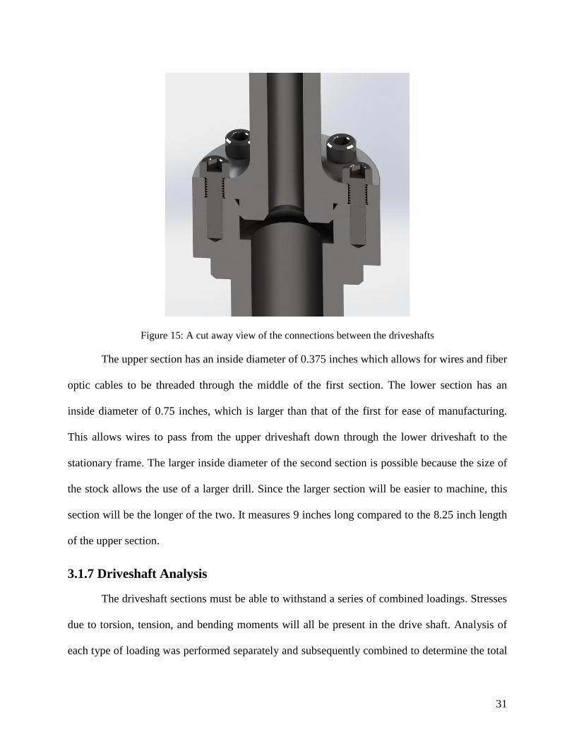
female connection. This connection is shown in Figure 15 along with the bolts and flanges.
Jesus Nut
Drive Pin Hole
31
Figure 15: A cut away view of the connections between the driveshafts
The upper section has an inside diameter of 0.375 inches which allows for wires and fiber
optic cables to be threaded through the middle of the first section. The lower section has an
inside diameter of 0.75 inches, which is larger than that of the first for ease of manufacturing.
This allows wires to pass from the upper driveshaft down through the lower driveshaft to the
stationary frame. The larger inside diameter of the second section is possible because the size of
the stock allows the use of a larger drill. Since the larger section will be easier to machine, this
section will be the longer of the two. It measures 9 inches long compared to the 8.25 inch length
of the upper section.
3.1.7 Driveshaft Analysis
The driveshaft sections must be able to withstand a series of combined loadings. Stresses
due to torsion, tension, and bending moments will all be present in the drive shaft. Analysis of
each type of loading was performed separately and subsequently combined to determine the total
32
resultant force on the driveshaft. Stresses in the driveshaft were analyzed at the point where the
highest stress concentrations are most likely to occur. This is the point where the upper
driveshaft expands from a diameter of 0.75” to one of 1.97” via a R.25” fillet in order to meet the
connecting flange.
Stress Concentrations
The fillet at the base of the upper driveshaft creates a stress concentration. Stress
concentration factors are found using experimentally tabulated values bases on part geometry.
The industry standard for obtaining these values is Peterson’s Stress Concentration Factors,
Second Edition, by Walter D. Pilkey. Pilkey’s resource was used for the calculations and the
graphs used are included in Appendix D.
Stress concentration factors were found for torsion, tension, and bending using the
driveshaft geometry. Each stress concentration was then multiplied by its respective forces
before continuing with the fatigue analysis. The details and results of these calculations can be
found in

33
Appendix E.
Torsion Calculations
Based on the inside and outside diameters stated above the torsion on each section was
calculated to ensure that the driveshaft sections were manufactured from a material strong
enough to withstand the torsion.
The torsion was calculated using the formula, shown by equation 2
𝜏𝑚𝑎𝑥 =
𝑇𝑐
𝐽 2
where T is the torque on the shaft and c is the distance from the center of gravity to the point
where the torsion is being calculated. Finally J is the polar moment, defined by equation 3
𝐽 =𝜋
2(𝑐𝑜
4 − 𝑐𝑖4) 3
where 𝑐𝑜 is the distance from the center of gravity to the outside edge of the shaft and 𝑐𝑖 is the
distance from the center of gravity to the inside edge of the shaft. This results in equation 4
𝜏𝑚𝑎𝑥 =
𝑇𝑐𝜋2
(𝑐𝑜4 − 𝑐𝑖
4) 4
In the case of the upper driveshaft, 𝑇 = 15 Nm which is the maximum torque the motor can
provide, 𝑐 = 𝑐𝑜 = 0.01905 meters (0.75 in) and 𝑐𝑖 = 0.009525 meters (0.375 in) leading to
a 𝜏𝑚𝑎𝑥 = 1.61 MPa.

34
Figure 16: Cross section showing in-plane forces and geometry.
Force Due to Lift
When the device is in motion, the lift force will be transmitted to the shaft. In most cases,
when there are no cyclic pitches commanded, the lift vector is purely vertical. However, with the
integration of cyclic controls, the resulting lift vector will shift from vertical to some angle as
demonstrated in Figure 17. As a note, these non-vertical lift forces are the forces which cause
forward flight.
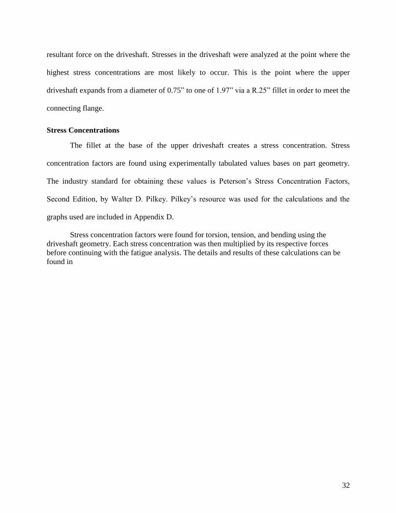
35
Figure 17: Total Lift Vector and Decomposition (Helicopter Flight Training Manual, 2010)
As shown in the decomposition on the right in Figure 17, the total lift force now has two
components, the vertical lift component and the horizontal lift component. The vertical force will
create a pure tensile stress on the driveshaft. With the addition of the horizontal lift force, a
bending moment will be created at the critical areas of the shaft.
This bending force is calculated first decomposing the total lift vector, given as:
𝐹𝐿𝑖𝑓𝑡,𝑥 = 𝐹𝐿𝑖𝑓𝑡𝑠𝑖𝑛(𝛽) 5
where 𝛽 is the angle between the axis of rotation and the total lift vector. Because the lift vector
acts at the center of rotation, the moment arm 𝑙, is simply the distance from point 𝐴 to point 𝐵
(see Figure 18). The bending moment at point 𝐵 due to lift is then given as:
𝑀𝐿𝑖𝑓𝑡,𝑥 = 𝐹𝐿𝑖𝑓𝑡,𝑥 × 𝑙 6
The stress created on the cross section is
𝜎𝐿𝑖𝑓𝑡,𝑥 =
𝑀𝐿𝑖𝑓𝑡,𝑥 × 𝑐
𝐽 7

36
where 𝑐 = 𝑐𝑜 for maximum stress and 𝐽, the polar area moment is equal to 𝜋
2(𝑐𝑜 − 𝑐𝑖)
4. For
reference geometry see Figure 19.
Figure 18: Free Body Diagram of forces due to lift.
Figure 19: Stress due to horizontal lift
37
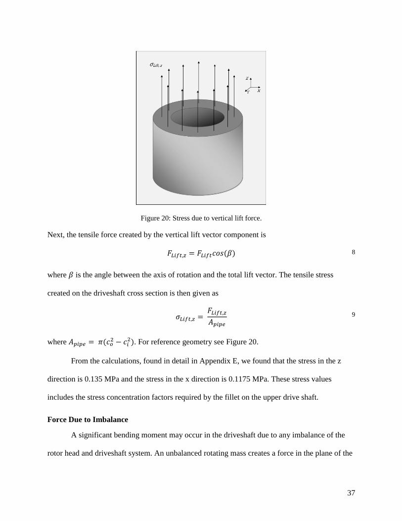
Figure 20: Stress due to vertical lift force.
Next, the tensile force created by the vertical lift vector component is
𝐹𝐿𝑖𝑓𝑡,𝑧 = 𝐹𝐿𝑖𝑓𝑡𝑐𝑜𝑠(𝛽) 8
where 𝛽 is the angle between the axis of rotation and the total lift vector. The tensile stress
created on the driveshaft cross section is then given as
𝜎𝐿𝑖𝑓𝑡,𝑧 =
𝐹𝐿𝑖𝑓𝑡,𝑧
𝐴𝑝𝑖𝑝𝑒 9
where 𝐴𝑝𝑖𝑝𝑒 = 𝜋(𝑐𝑜2 − 𝑐𝑖
2). For reference geometry see Figure 20.
From the calculations, found in detail in Appendix E, we found that the stress in the z
direction is 0.135 MPa and the stress in the x direction is 0.1175 MPa. These stress values
includes the stress concentration factors required by the fillet on the upper drive shaft.
Force Due to Imbalance
A significant bending moment may occur in the driveshaft due to any imbalance of the
rotor head and driveshaft system. An unbalanced rotating mass creates a force in the plane of the
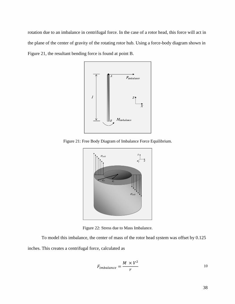
38
rotation due to an imbalance in centrifugal force. In the case of a rotor head, this force will act in
the plane of the center of gravity of the rotating rotor hub. Using a force-body diagram shown in
Figure 21, the resultant bending force is found at point B.
Figure 21: Free Body Diagram of Imbalance Force Equilibrium.
Figure 22: Stress due to Mass Imbalance.
To model this imbalance, the center of mass of the rotor head system was offset by 0.125
inches. This creates a centrifugal force, calculated as
𝐹𝑖𝑚𝑏𝑎𝑙𝑎𝑛𝑐𝑒 =
𝑀 × 𝑉2
𝑟 10

39
where 𝑀 is the mass of the rotor head and blades, 𝑉 = 𝑟Ω = 2𝜋𝑟
60× 𝑅𝑃𝑀, and 𝑟 is the distance
from the rotation axis to the center of gravity of the rotor head. Through substitution and
simplification, the imbalance force can be calculated as:
𝐹𝑖𝑚𝑏𝑎𝑙𝑎𝑛𝑐𝑒 =
4𝜋2
3600𝑀𝑟 × 𝑅𝑃𝑀2 11
Multiplying by the moment arm gives the bending moment at point B:
𝑀𝑖𝑚𝑏𝑎𝑙𝑎𝑛𝑐𝑒 =
4𝜋2
3600𝑀𝑟 × 𝑅𝑃𝑀2 × 𝑙 12
The stress created at point B can be found using the following equation
𝜎𝑖𝑚𝑏 =
𝑀𝑖𝑚𝑏𝑎𝑙𝑎𝑛𝑐𝑒 × 𝑐
𝐽 13
where 𝑐 = 𝑐𝑜 for the maximum stress (Figure 16), and 𝐽 = 𝜋
2(𝑐𝑜 − 𝑐𝑖)
4, the polar area moment.
As calculated in Appendix E, the stress due to imbalance 𝜎𝑖𝑚𝑏 was 11.43 MPa.
Cyclic Loading
In addition to the series of combined loadings, the drive shaft will also be subjected to a
cyclic loading. At the critical areas of the shaft, there will be a constant cycle of tensile and
compressive loadings due primarily to the bending moments.
Imagine the shaft rotating at a constant velocity with a certain imbalance. As shown in
Figure 23 and Figure 24, this creates a force 𝐹𝑖𝑚𝑏𝑎𝑙𝑎𝑛𝑐𝑒 which becomes a moment 𝑀𝑖𝑚𝑏𝑎𝑙𝑎𝑛𝑐𝑒 at
point B. Because the force 𝐹𝑖𝑚𝑏𝑎𝑙𝑎𝑛𝑐𝑒 is rotating with the drive shaft, the moment also rotates,
causing a constant state of tension/compression on the corresponding areas of the shaft. Adding
the horizontal lift force due to cyclic pitch, 𝐹𝐿𝑖𝑓𝑡,𝑥, will cause a reaction moment 𝑀𝐿𝑖𝑓𝑡,𝑥 at point
B. Contrary to the imbalance force, the lift force does not rotate with the shaft, but instead acts in
a fixed direction. The most important instances to analyze are when the two forces act in the

40
same direction and in opposite directions. The resulting case of minimum bending moment is
shown in Figure 23 and the case of maximum bending moment is shown in Figure 24. Both
Figure 23 and Figure 24 are shown with a reference frame attached to the driveshaft so that the
sign convention of the resulting forces and moments will be consistent.
Figure 23: Minimum net moment FBD
Figure 24: Maximum net moment FBD
At point B, the combination of the lift and imbalance forces results in two bending moments and
one force. For the maximum case, these forces sum to
𝜎𝑚𝑎𝑥 = 𝜎𝑖𝑚𝑏,𝑚𝑎𝑥 + 𝜎𝑙𝑖𝑓𝑡,𝑧 + 𝜎𝑙𝑖𝑓𝑡,𝑥 𝑚𝑎𝑥 14
For the minimum case the stresses sum to
𝜎𝑚𝑖𝑛 = 𝜎𝑖𝑚𝑏,𝑚𝑎𝑥 + 𝜎𝑙𝑖𝑓𝑡,𝑧 − 𝜎𝑙𝑖𝑓𝑡,𝑥 𝑚𝑎𝑥 15
This combined stress field results in a tensile force which varies in magnitude along the cross
section of the shaft. Toward the outer edges of the shaft the tensile stresses are increased in a

41
linear fashion. Depending on the direction of the lift vector, one side of the shaft will have a
higher stress than the other. The stress field is illustrated in Figure 25, with 𝜎𝑚𝑎𝑥 and 𝜎𝑚𝑖𝑛
shown. From the calculations detailed in Appendix E, 𝜎𝑚𝑎𝑥 and 𝜎𝑚𝑖𝑛 were found to be 11.82
MPa and 11.59 MPa respectively.
Figure 25: Combined stresses due to lift and imbalance forces
Differential Element Stress Analysis
Because the torsional and bending forces act on the same point, they cannot be analyzed
separately. In order to determine the single force resulting from their combination an elemental
analysis must be employed. Figure 26 shows the stresses on a differential element located in the
plane of interest.

42
Figure 26: Stress on a differential element.
The maximum normal stress occurs when the element is set at an angle where there is no
shear stress applied. The normal stress resulting from this case is called the principal stress.
There are two principal stresses 𝜎1 and 𝜎2, where 𝜎1 > 𝜎2 as found using the following equation:
𝜎1,2 = 𝜎𝑧 + 𝜎𝑦
2 ± √(
𝜎𝑧 − 𝜎𝑦
2)
2
− 𝜏𝑦𝑧2
16
The value 𝜎1 was used for the rest of the analysis since it is greater in magnitude than 𝜎2.
The maximum shear stress was found in a similar manner using equation 17
𝜏𝑚𝑎𝑥,𝑖𝑛 𝑝𝑙𝑎𝑛𝑒 = √(𝜎𝑧 − 𝜎𝑦
2)
2
− 𝜏𝑦𝑧2
17
The physical significance of each term in Figure 26 and equations 16 and 17 are now
presented. The vertical normal stress, 𝜎𝑧, is a result of the forces due to lift and bending, shown
in Figure 26. The shear stress, 𝜏𝑦𝑧, is a result of the torsion, shown in Figure 16. The second
shear stress shown on the y face, 𝜏𝑥𝑧, is required to maintain equilibrium within the differential

43
element. The second normal stress, also on the y face, is shown for reference to equations 18 and
19. However, for this loading, 𝜎𝑦 ≈ 0, so equations 16 and 17 simplify to
𝜎1 = 𝜎𝑧
2 ± √(
𝜎𝑧
2)
2
− 𝜏𝑦𝑧2
18
and
where 𝜎𝑧 is 𝜎𝑚𝑎𝑥 or 𝜎𝑚𝑖𝑛.
Equation 18 yields a maximum tensile stress of 11.8 MPa, and Equation 19 yields a
maximum shear stress of 5.7 MPa. Using an 1144 stress proof low carbon steel with a yield
stress of 620 MPa gives a safety factor of 52 for tension and 109 for shear.
Fatigue Calculations
In order to assess the life cycle of our drive shaft design, a fatigue analysis was
performed at the flange on the upper driveshaft, the point most likely to fail. The mean stress and
stress amplitude at this location were calculated using equations 20 and 21
𝜎𝑚𝑒𝑎𝑛 =𝜎1,𝑚𝑎𝑥 + 𝜎1,𝑚𝑖𝑛
2 20
and
𝜎𝑎 =𝜎1,𝑚𝑎𝑥 − 𝜎1,𝑚𝑖𝑛
2 21
Once the values of the stresses at the flange were calculated, the fatigue life was
extrapolated from a fatigue cycle analysis graph, depicted in Figure 27. Using a stress of 1.7 ksi
𝜏𝑚𝑎𝑥,𝑖𝑛 𝑝𝑙𝑎𝑛𝑒 = √(𝜎𝑧
2)
2
− 𝜏𝑦𝑧2
19

44
as calculated, this resulted in an expected fatigue life of unlimited hours due to the fact that stress
is below 1144 steels fatigue limit.
\
Figure 27: An S-N curve for mild steels. We are using 1144 steel which is .44% carbon (Lienhard)
3.1.8 Support Bearing Design
Supporting the lower driveshaft is a pair of Conrad type ball bearings. These bearings
serve two purposes: first, to allow the driveshaft to rotate freely, and second, to support the
driveshaft axially, i.e., transmit vertical forces to the test stand frame. The two bearings will be
spaced along the shaft to provide better resistance to moments applied at either end of the shaft.
The bearing type we will use is Fafnir 206K light duty bearing. We chose these bearings
because they were available to us for no cost and their internal and external diameters of 30 and
62 millimeters respectively met our design requirements for the driveshaft.
After choosing these bearings we performed a life cycle assessment on them to get a clear
picture of how long they would last. We did this by using the life cycle formula depicted in
equation 22

45
𝐿10 = 1500 (
𝐶𝑁
𝑅𝐸)
3
22
Equation 22 was provided by Fafnir where 𝐶𝑁 is the radial load rating at the operating speed and
𝑅𝐸 is the equivalent radial load. More specifically
𝐶𝑁 = 𝑛𝑓 × 𝐶𝐵 23
where 𝑛𝑓 is the speed rating read from a Fafnir chart (Timken, 2015) and 𝐶𝐵is the basic radial
reference load provided by Fafnir. The value 𝑅𝐸 is found using the greater of the following
equations 24 and 25:
𝑅𝐸1 = 𝑋1𝑉𝑅 + 𝑌1𝑇 24
𝑅𝐸2 = 𝑋2𝑉𝑅 + 𝑌2𝑇 25
where R is the radial load in lb., T is the thrust load in lb.,
𝑉 = 1.2, 𝑋1 = 1, 𝑌1 = 0, 𝑋2 = .56, and 𝑌2 =𝑇
𝑛𝑑2.
After substitution and using a T of 30 lb., an R of 50 lb., an nd2 of 1.32, an nf of .28 and a CB of
3570, this leads to
𝑅𝐸1 = 60,
𝑅𝐸2 = 715.42,
and
𝐶𝐵 = 999.6
meaning that RE2 and CB will be plugged into the L10 equation. This resulted in a life expectancy
of 4,091 hours, or about 170 days of continuous operation, before the bearings fail.
The upper and lower bearings are pressed into aluminum plates and separated by an
aluminum spacer tube. The bearings are slip fit onto the driveshaft, which has its vertical motion
restrained by a locknut on one side and the flange of the lower driveshaft on the other.

46
3.1.9 Swashplate Design
The purpose of the swashplate is to transfer pitch control inputs from the stationary frame
to the rotating frame. The sensitivity of the input and transfer controls, or the amount of travel
required, is determined by the required change in pitch of each blade. A typical helicopter
operates at blade angles of attack between -5 and 15 degrees. Negative angles of attack may be
necessary to achieve zero lift if the blades have axial twist.
Figure 28: The scissor link from the University of Dayton Research Institute (University of Dayton
Research Institute, 2014).
The length of the lever arm created by the offset of the control arm, shown in Figure 28,
and the angle of pitch required for the blades means that the control rod needs approximately 0.5
inches of travel. From this, the swashplate also needs to be able to travel 0.5 inches vertically
along the driveshaft. This must be combined with the swashplates ability to tilt relative to the
horizontal axis, allowing cyclic control for simulating forward flight.
Control Arms
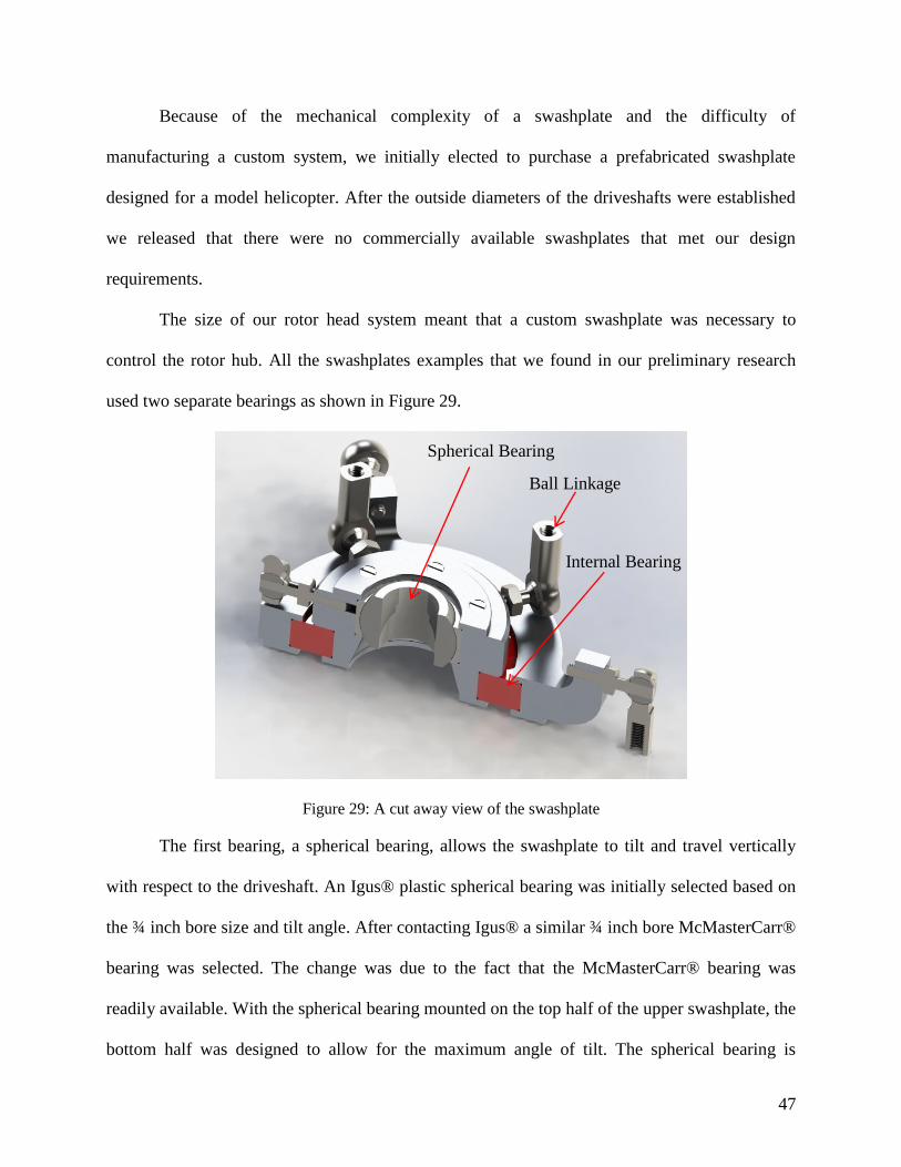
47
Because of the mechanical complexity of a swashplate and the difficulty of
manufacturing a custom system, we initially elected to purchase a prefabricated swashplate
designed for a model helicopter. After the outside diameters of the driveshafts were established
we released that there were no commercially available swashplates that met our design
requirements.
The size of our rotor head system meant that a custom swashplate was necessary to
control the rotor hub. All the swashplates examples that we found in our preliminary research
used two separate bearings as shown in Figure 29.
Figure 29: A cut away view of the swashplate
The first bearing, a spherical bearing, allows the swashplate to tilt and travel vertically
with respect to the driveshaft. An Igus® plastic spherical bearing was initially selected based on
the ¾ inch bore size and tilt angle. After contacting Igus® a similar ¾ inch bore McMasterCarr®
bearing was selected. The change was due to the fact that the McMasterCarr® bearing was
readily available. With the spherical bearing mounted on the top half of the upper swashplate, the
bottom half was designed to allow for the maximum angle of tilt. The spherical bearing is
Spherical Bearing
Ball Linkage
Internal Bearing

48
mounted in the upper swashplate by a press fit. This is backed up by the use of a retaining ring
which is mounted on the upper swashplate using 6 3/8 inch #4-40 flat head machine screws.
Figure 30: The two bearings used in the swashplate
The second bearing, a ball bearing, allows the upper and lower swashplate sections to
rotate independently. For this internal bearing we initially selected a thin section, x-type 4 point
contact, bearing by Silverthin®. This bearing had a thickness of only .25 inches, but again due to
time constraints in manufacturing and shipping another bearing was chosen. The bearing that is
in the final iteration of the swashplate is a Timken Ultra-Light series 9310K. This bearing has a
bore of 50 millimeters, an outside diameter of 72 millimeters and a thickness of 12 millimeters.
Because of the change in the thickness of the internal bearings the overall thickness of the
swashplate increased to accommodate the larger size of the new bearing. The bearing is pressed
fit into both the upper and lower halves of the swashplate and in both cased the press fit is
backed up by a retaining ring that is fastened to each respective half of the swashplate using 6 3/8
inch #4-40 flat head machine screws.

49
Figure 31: A Bottom view of the swashplate illustrating the two retaining rings.
In order to connect the swashplate with the rotor hub and the control servos we elected to
use ball links. We choose ball links because transmit the vertical force of the control servo but
allow the swashplate and control arms to pivot and tilt. The links in our preliminary designs
consisted of a plastic M5 ball and socket type link from Igus®. After contacting Igus® we chose
to use an alternative ball link from McMasterCarr® because they were available immediately.
These links, shown in Figure 32, are all metal and have #10-32 thread.
In order to keep the control links all in the same plane the lower swashplate has control
horns that raise 0.55 inches to the match the control plane of the upper swashplate. Each ball
link’s male thread is threaded into its respective half of the swashplate or rotor head. The female
half of the ball links is attached to #10-32 threaded rod. Threaded rod is used to complete the
control links by attaching the lower swashplate with the control servos and the upper swashplate
with the rotor hub. The ball links are also used to attach each half of the swashplate to its
Internal Bearing Retaining Ring

50
respective torque link. In total there are 13 ball links in our design, 4 of which are found on the
rotor head, 5 on the upper swashplate, and the final 4 on the lower swashplate.
Figure 32: All metal #10-32 ball links from McMasterCarr®
3.1.10 Swashplate Torque Link Design
Torque Link Components
Since the upper half of the swashplate is located in the rotating frame and the lower half
of the swashplate is located in the stationary frame, it is important to ensure that the upper half
rotates at exactly the same speed as the rotor head while the lower half remains stationary. This
is achieved by connecting the lower half of the swashplate to a fixed object and the upper half to
the rotor head. The only caveat to this is that the swashplate must still be free to tilt and move in
the vertical direction.
One option to limit the motion of the lower half and transmit the motion of the upper half
is to just use the control linkages as torque links. The down fall of this is that the control linkages
are comparatively fragile and are not designed to handle the torque and transmit control inputs.
Therefore, two scissor links were designed.

51
The upper scissor link, shown in Figure 33 connects directly from a clamp on the
driveshaft to the upper half of the swashplate. This transmits the torque from the driveshaft to the
upper half of the swashplate forcing it to rotate at the same angular velocity. The clamp is a
simple, two part, friction style clamp who internal radius matches the outside diameter of the
upper driveshaft. It uses two 0.25 inch bolts to clamp down on the driveshaft. The clamp is
connected to one side of an elbow. The other side of this elbow is connected to a ball link. The
elbow in conjunction with the ball link allows the swashplate to travel vertically and tilt while
still transmitting the rotational motion from the clamp to the upper half of the swashplate.
Figure 33: The upper torque link and driveshaft clamp
The lower scissor link operates in much the same way. The only difference is that instead
of a clamp the elbow is connected directly to the servo mounting plate. This eliminates any
rotation that is transmitted thought the internal bearing while still allowing the swashplate to tilt
and travel up and down.
In both cases the friction at the elbow is small enough that we decided to forgo any sort
of bearings. Although we have not incorporated them into our scissor links, we allotted space in

52
our design for nylon washers and inserts that could be used to negate any friction and allow for
smooth vertical motion.
Follower Stress Analysis
The weakest point in the design of both scissor links is the #10-32 threaded rod. In the
case of the upper scissor link the rod is placed in pure shear because it transmits the shaft torsion
to the upper swashplate and must be mounted exactly vertical due to clearance issues with the
control rods.
Using equation 26 the maximum shear stress can be calculated,
𝜏𝑀𝑎𝑥=
𝐹𝐴
26
where A is the cross sectional area which based on the #10 minor diameter of 0.1508 inches is
0.0178 square inches and an F of 200 lbf is the maximum estimated force the rod will be
subjected to. This results in a shear stress of 11.19 ksi. When this is compared to 11,500 ksi
which is the maximum allowable shear stress for A36 steel we can safely say that the threaded
rod will not snap.
After ensuring that the control rods would not break, it was important to figure out if they
would bend or deform. To do this the same equation, equation 26, was used to calculate the
stress on the rod. Using the same parameters as shear stress calculation, this resulted in a stress
of 11.19 ksi. To understand if the rod would bend this is compared to A36 steel’s yield strength
of 36 ksi. Based on this it is clear that the material will not bend, in fact based on the geometry of
the control rods a force of 642 lbf would be need bend them.
In the case of the lower scissor link the forces will be much less due to the internal
swashplate bearing and the rod can be angled so that it is placed in compression as well as shear.
Base on this it is safe to say that the upper link will fail before the lower one.

53
3.1.11 Pitch Control System
The pitch control system is designed to move the lower nonrotating half of the swashplate
via the lower control links. This causes the upper half of the swashplate to move and thru the
upper control linkages forces the rotor head to adjust the pitch of each blade.
It does this by moving the 3 lower control linkages in the vertical direction. To achieve
collective control all 3 linkages are moved at the same rate and time. To provide cyclic pitch
control each control linkage would be moved on its own at its own rate.
Throughout our design process there has been three methods for pitch control. The first
and simplest method is to use lead screws. This would require 1 lead screw per control rod for a
total of 3. To change the pitch of the blades the lead screws would be adjusted as necessary. The
down side to this system is that due to the fact the lead screws must be mounted on the servo
mounting plate they could only be adjusted when the motor was off. The second option second
option is to connect the lower control linkages to a mechanical system that through the use of
pulleys and cables connected to joystick like control faces. This system would be very similar to
that of an actual helicopter. It would require two separate control interfaces for collective and
cyclic controls. The advantage that this system has over lead screws is that the pitch of the blade
could be adjusted while the motor was running. The final option we considered is the use of
digital control servos. This would require 3 servos, one for each of the lower control linkages.
The servos would be controlled through a computer program such as LabView. Although this is
the most complex and expensive option it has the advantage of being remotely controlled and it
is the only option that can be fully integrated with the data acquisition system.

54
3.1.12 Rotor Head Design
The driving factor for the final diameter of the rotor head was spatial constraints. This
was because the lab that the test stand is designed to operate in has very limited space. It was
determined that the maximum allowable rotor diameter for the lab was around 1.5 meter. This
required us to scale our rotor head and all its parameter to fit the lab. Scaling of the rotor head
provided the necessary information on the rotational speed for the proper simulation of a full
scale helicopter. This was done by matching the tip Mach number of the scaled rotor blades with
the actual tip Mach number of a full scale helicopter. The result of the scaling led to a stand that
is designed to operate with any rotor head system up to 1.5 meters in diameter.
Fully Articulating Rotor Head
In order to better simulate the conditions a full scale helicopter experiences we chose to
design a fully articulated rotor head. This was because the fully articulated system provides
considerable control and flexibility at the small scale sizes we are working with. By allowing the
blade grip assemblies to rotate around all three primary axes via the feathering, drag, and
flapping hinges, our fully articulated rotor head designed to minimize the stresses put on it in
hovering conditions. Additionally, a fully articulated rotor head allows testing a greater variety
of hovering conditions.
Figure 34: The fully articulated rotor head pictured without the driveshaft or blades
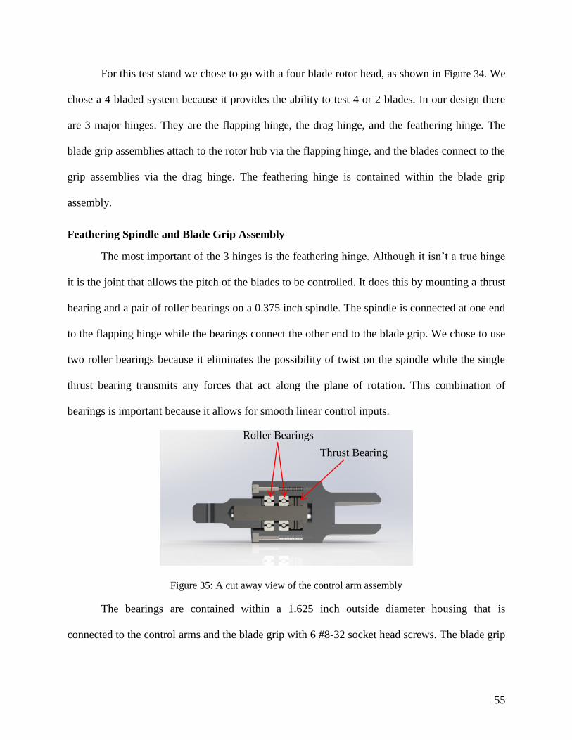
55
For this test stand we chose to go with a four blade rotor head, as shown in Figure 34. We
chose a 4 bladed system because it provides the ability to test 4 or 2 blades. In our design there
are 3 major hinges. They are the flapping hinge, the drag hinge, and the feathering hinge. The
blade grip assemblies attach to the rotor hub via the flapping hinge, and the blades connect to the
grip assemblies via the drag hinge. The feathering hinge is contained within the blade grip
assembly.
Feathering Spindle and Blade Grip Assembly
The most important of the 3 hinges is the feathering hinge. Although it isn’t a true hinge
it is the joint that allows the pitch of the blades to be controlled. It does this by mounting a thrust
bearing and a pair of roller bearings on a 0.375 inch spindle. The spindle is connected at one end
to the flapping hinge while the bearings connect the other end to the blade grip. We chose to use
two roller bearings because it eliminates the possibility of twist on the spindle while the single
thrust bearing transmits any forces that act along the plane of rotation. This combination of
bearings is important because it allows for smooth linear control inputs.
Figure 35: A cut away view of the control arm assembly
The bearings are contained within a 1.625 inch outside diameter housing that is
connected to the control arms and the blade grip with 6 #8-32 socket head screws. The blade grip
Thrust Bearing
Roller Bearings

56
contains a 14 mm wide by 30 mm deep slot that the rotor blade mounts into. The blade grip
connects to the rotor blade with a single M5 screw.
Figure 36: Control arm face plate viewed from the top down.
The control arm is bolted to the blade grip and bearing housing using the same 6 #8-32
socket head screws. The control arms control horn is connected to a ball link which connects it to
the swashplate. The control horn is design so that at zero angle of attack on the blade the control
linkages are perpendicular to the horizontal plane.
Figure 37: Side view of the blade grip
Flapping Hinge
The feathering spindle is connected to the flapping hinge by a 1 inch 0.1875 inch OD
steel clevis pin. The pin passes through the end of the feathering spindle as well as the flapping
Ball Linkage Hole

57
hinge and is held in place by a cotter pin. The flapping hinge, which allows each blade to flap up
and down to reduce stress, is 1.8 inches long with a ¾ inch outside diameter. The innermost end
is squared off so that it acts as a droop stop and prevents the blades from sagging below the
horizontal plate of the rotor head when the motor isn’t operating. The flapping hinge is
connected to the rotor hub by a 1.625 inch ¼ inch OD clevis pin.
Figure 38: Side view of the flapping hinge.
Rotor Hub
Largest piece of the rotor head design is the rotor hub. It transfers the rotational motion
and torque from the driveshaft to the blade grips which passes it on the rotor blades. Because of
this the rotor hub is subject to the larges forces of our entire rotor head. With this in mind we
decided to design our rotor hub out of a single piece of 6061T6 aluminum. We did this to
eliminate joints and minimize the overall size of our rotor hub. The final overall dimensions of
the rotor hub are 3.175 by 3.175 by 1.6 inches. The lower 0.8 inch half of the rotor hub is a 1.2
inch diameter cylinder that is expands into the upper 0.8” of rotor hub via a 0.1875” radius fillet.
Droop Stop

58
Figure 39: Side top view of the rotor hub
Since our design specification called for a rotor head that could accommodate up to 4
rotor blades our rotor hub was designed to this. It has 4 0.8875 by 0.6 inch slots that the flapping
hinges are centered in. The pins that connect the flapping hinges to the rotor hub pass through the
0.4 inch thick arms of the slots via ¼ inch holes that are centered with respect to the arms. The
top of each arm is 0.25” fillet on to allow the rotor blades to flap up unhindered. The rotor hub is
connected concentrically the driveshaft via a combination of a 0.75 inch diameter through hole
which the upper driveshaft passes through and 0.25 inch pin. The 0.25” diameter pin serves two
purposes. It prevents the rotor head from sliding down the driveshaft and at the same time it
forces rotor head to rotate at the same angular velocity as the driveshaft.
Stresses on the Rotor head
In order to determine if the rotor head design will withstand the forces it will be subjected
to during normal operations, the maximum forces and moments were calculated. The forces were
needed to calculate the stresses on individual components while the moments were used to

59
Figure 40: Principal Forces and Moments on the Rotor Hub
calculate the coning angle. By calculating the coning angle it was possible to evaluation of the
various force components. The two most significant forces and moments on the components are
those generated by the centrifugal force and the lift force as shown in Figure 40.
The rotor head is designed to operate between 1000 to 1350 rpms with a maximum radius
of 0.6 meters based on this the forces and moments are calculated using 1500rpms. By using
1500rpm a margin of safety was built directly into the calculations.
When the moment generated by centrifugal force and moment generated by lift are equal
the coning angle can be calculated. This is done by setting the equation 27
𝑀𝑐𝑓 = ∫ 𝑚𝛺2𝑦2𝛽𝑑𝑦
𝑟
𝑒𝑟
27
equal to equation 28
𝑀𝐿𝑦= − ∫ 𝐿𝑦𝑑𝑦
𝑟
𝑒𝑟
28
and solving for β. This yields formula, shown in equation 29
𝛽 =
3 ∫ 𝐿𝑦𝑑𝑦𝑟
𝑒𝑟
∫ 𝑚𝛺2𝑦2𝛽𝑑𝑦𝑟
𝑒𝑟
29

60
after simplifications this leads to equation 30.
𝛽 =
3 ∫ 𝐿𝑦𝑑𝑦𝑟
𝑒𝑟
𝑚𝛺2𝑟3(1 − 𝑒3)
30
This results 𝛽 ≈ 2° degrees when using an untwisted NACA 0012 airfoil spinning at
1500 RPMs and were r = 0.6m and er = .06m.
The component of force that acts horizontally outwards can be calculated using equation
31
𝐹𝑛𝑒𝑡 = √𝐹𝑥2 + 𝐹𝑧
2 31
Where
𝐹𝑥 = 𝐹𝑐𝑓 − 𝐹𝐿𝑥
and
𝐹𝑧 = 𝐹𝐿𝑧
32
This can be further broken down using the coning angle to obtain equation 33
𝐹𝐿𝑥 = 𝐹𝐿 sin 𝛽
𝐹𝐿𝑧 = 𝐹𝐿 cos 𝛽
33
and equation 34.
𝐹𝑐𝑓 = ∫ 𝑚𝛺2𝑦𝑑𝑦 =𝑚𝛺2(𝑟2 − 𝑒𝑟2)
2
𝑟
𝑒𝑟
34
Then after substitution this leads to the equation 35
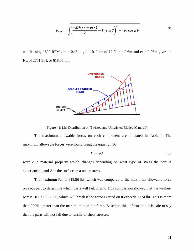
61
𝐹𝑛𝑒𝑡 = √(𝑚𝛺2(𝑟2 − 𝑒𝑟2)
2− 𝐹𝐿 sin 𝛽)
2
+ (𝐹𝐿 cos 𝛽)2 35
which using 1800 RPMs, m = 0.434 kg, a lift force of 12 N, r = 0.6m and er = 0.06m gives an
Fnet of 2751.9 N, or 618.65 lbf.
Figure 41: Lift Distribution on Twisted and Untwisted Blades (Cantrell)
The maximum allowable forces on each component are tabulated in Table 4. The
maximum allowable forces were found using the equation 36
𝐹 = 𝜎𝐴 36
were σ a material property which changes depending on what type of stress the part is
experiencing and A is the surface area under stress.
The maximum Fnet is 618.56 lbf, which was compared to the maximum allowable force
on each part to determine which parts will fail, if any. This comparison showed that the weakest
part is HHTS-002-006, which will break if the force exerted on it exceeds 1374 lbf. This is more
than 200% greater than the maximum possible force. Based on this information it is safe to say
that the parts will not fail due to tensile or shear stresses.

62
Table 4: Maximum Forces on Each Component
Location of Force N lbf
Max force on HHTS-003-002 9424.8 2120.6
Max force on HHTS-003-001 32903 7403.2
Max force on HHTS-002-001 10282 2313.5
Max force on HHTS-002-006 6108.9 1374.5
Max Force on HHTS-002-003 at HHTS-002-006 9329.8 2099.2
Max Force on HHTS-002-001 at HHTS-002-006 9613.3 2163
Max Force on HHTS-002-002 at its head 17671 3976
Max Force on HHTS-001-006 at HHTS-002-002 24939 5606
Max Force on HHTS-002-002 at HHTS-001-006 72024 16205.4
Max Force on interior HHTS-001-001 9260.6 2083.6
Max Force on Blade Grip Hole 9139.2 2056.3
3.1.13 Design for Manufacturing
With a complex assembly such as our rotor head, manufacturing limitations were
considered in the design. While performing conceptual and CAD design of the rotor internal
radii, hole and tap sizes were selected to ease manufacturing. When milling, the internal radius is
limited by the size of the tool used. For example, when using a .25 inch diameter tool, the
minimum radius which can be machined is 0.125 inches. Internal radii were made as large as
possible to allow the use of the largest tool possible for more robust machining. The internal
radius design is especially important on the rotor hub, where a small radius is ideal for clearance
around the flapping hinge. The internal radius of the rotor hub was optimized for the most
compact clearance, and for use of a common sized end mill.

63
Hole and tap sizes were designed to be constant across the entire assembly when
possible. For machining, common screw size and type reduces the variety of drills and taps
required. This also simplifies hardware procurement and assembly.
3.1.14 Computer-Aided Design
Prior to manufacturing a Solidworks model was created to help dimension the sizes and
clearances of each part and assembly. Each part was modeled to accurately represent the actual
part on a 1:1 scale. All of the parts were assigned respective material properties, including
density and yield strength, so that simulations, moments of inertia, and weights could be
observed in Solidworks. Each part and assembly was given a part and assembly number
designation and instructions on how to assemble them.
The rotor hub parts were subsequently combined into two subassemblies. The first
contained the bearings for the feathering spindle and the control arm. The second contains the
feathering spindle, blade grip, and flapping hinge. These two subassemblies were combined with
the rotor hub and necessary fasteners to create the rotor head assembly.
The rotor head assembly was then combined with the driveshaft and control assemblies.
The drive shaft assembly is made up of the upper and lower sections, the driveshaft drive pulley,
the driveshaft bearings and all of the required fasteners. The control assembly contains the pitch
control servos, the swashplate, the scissors link, and the control arms. These assemblies and the
rotor blades are combined into a single rotor assembly.
The final two subassemblies are the stand assembly and the engine and engine mount
assembly. The stand assembly comprises the frame and safety system on which the rotor head,
drive shafts, control system, and engine are mounted. The engine and engine mount assembly
contains the engine model, the engine drive pulley, the engine mounts and required fasteners.

64
Finally the stand, rotor assembly, and engine and engine mount assembly are combined
into a single assembly that represents the entire design.
Each part was then represented in a drawing for manufacturing of the parts in-house. The
drawings contained all of the necessary dimensions, tolerances, and other information required
for manufacturing. Drawings were also created for all of the sub-assemblies and the final
assembly. The subassembly drawings contain assembly instructions, fastener types, information
on where thread-lock or thread-locking wire is recommended, and reference dimensions. The
final assembly drawing contains the necessary information for assembling the subassemblies.

65
3.2 Budgeting
The funding provided to this MQP through the WPI Aerospace Engineering Department
was $160.00 per student, or $480.00 total. After the initial research it was quickly determined
that this budget would not be sufficient. Any data acquisition system or slip ring would cost
thousands of dollars, and a low cost motor and VFD combination would cost several hundred. As
a first attempt to secure more funding we attempted to contact helicopter and component supplier
companies explaining our research and the need for additional funding. Of these cold contacted
companies we had no responses. The only aid we were able to secure was from J&E Precision
Tool Inc., a manufacturing company which also employed a member of our team. Through that
existing relationship, J&E offered access to their excess raw material stock and scrap.
The first two-thirds of this project were advised by Professor Maria Chierichetti, who
created the initial requirements and had a specific use intended for this device. With her research
funding through the Structural Vibrations lab which she administered, she agreed to purchase a
fiber-optic strain measuring system. After being required to change advisors to Professor
Anthony Linn, the MQP lost access to the research funding provided by Professor Chierichetti.
The small budget has severely affected the design of the helicopter hover test stand. All
efforts were taken in the design stage to stay within the budget. One of the most time and energy
consuming compromises was being forced to design and manufacture a rotor hub and swashplate
system. These systems are readily commercially available, but were too expensive for us to
consider.
Our final itemized budget is included in

66
Appendix F.

67
3.3 Manufacturing
3.3.1 Process Documentation
Due to the large number of complex parts included in the rotor head assembly, a process
documentation system was created. Manufacturing process sheets were developed to outline the
steps involved in manufacturing each particular part and assembly. They feature part
identification, a list of operations, and record quantities and dates of parts produced. The purpose
of the process sheets is to ensure part quality and traceability, with the secondary purpose of
allowing future collaborators to modify or remanufacture parts.
The operation lists outline the detailed steps taken to manufacture each part. These
documents contain setup and tooling information, computer numeric controlled (CNC) programs,
and a dimensioned drawing for inspection.
A sample of these manufacturing and operation sheets were included in Appendix B, as
well as published in a binder to be kept with the testing apparatus should modifications be
necessary. All CNC and CAD files were also published to a USB drive to be stored in the
manufacturing binder.
3.3.2 Computer-Aided Machining
Computer-Aided Machining (CAM) was performed when CNC machining equipment
was desired. The CAM software used was ESPRIT, which utilizes reference geometry to create
tool paths which produce the desired part. The program outputs this tool path information as a G-
code, which is a system of commands and coordinate points which control the CNC machines.
For a particular part, there may be multiple set-ups required in order to complete the part.
These set-ups must be planned in conjunction with the CAM programming.

68
3.4 Safety Enclosure
A very important aspect of the design of the helicopter hover test stand is the safety
enclosure. Without it, it is too dangerous to run the system. That being said, the safety enclosure
must be able to successfully contain any and all parts that come off of the rotor hub. This means
that, in the event of a failure during testing, the safety system must provide complete protection
to the operator and any other occupants of the lab.
The preliminary conceptual design of the system used a wire mesh, such as chain link, to
completely surround the test stand and contain any large parts that break off during testing. The
problem with the preliminary design was the size of the wire mesh, which limited the size of
piece that could be contained to the size of the chain link. Any object smaller than the gaps in the
chain link would pass though the safety system without any loss of energy.
To eliminate the possibility of small pieces passing through a wire mesh barrier, the next
conceptual design incorporated solid barriers. It used 4 solid sheets that, when connected to each
other, form a box around the helicopter hover test stand. When the stand is not in use the box can
be broken down into individual sheets to maximize lab space and easy storage. One possibility
for the sheet material is plywood with a Lexan viewing window.
Another option for the solid barriers was steel sheets backed by steel ribs. They would
form a barrier of approximately 60”x60” that would be mounted at the height of the rotor hub. In
addition to the steel sheets the system would have a mesh that extended below the sheets to
contain anything that fell below the main containment sheets. An advantage to this containment
system that it is very strong for its weight, however it would require its own stand and is more
difficult to breakdown for storage.

69
After debating the advantages and disadvantages to each type of system, we settled on the
steel barrier containment system. This was because it provides the best strength to weight of all
the options available and it provides more complete containment unlike wire mesh. Another
large factor in the decision to use a steel sheet containment system was the price. It is important
to note that old wind tunnel ducts were donated to our project and with some minor
modifications were converted into the containment system.

70
3.5 Assembly
The following subsections are meant to supplement the assembly drawings contained in
Appendix A. They describe the basic assembly process for each individual assembly.
3.5.1 Feathering Spindle Assembly
To assemble the feathering spindle assembly (HHTS-001), begin with the bearing
housing (HHTS-001-001) itself. First, the two roller bearings (HHTS-001-003) were seated in
the center hole, followed by a washer (HHTS-001-005). Next, a thrust bearing (HHTS-001-004)
was placed on top of the washer (HHTS-001-005) on the deeper side of the bore. This was also
followed by a washer (HHTS-001-005). The assembly was completed by adding the faceplate
control arm (HHTS-001-002) opposite the thrust bearing. This process was repeated 4 times,
once for each of the thrust bearing housings.
3.5.2 Pitch Control Arm Assembly
First, to begin assembling the pitch arms, the feathering spindle (HHTS-002-003) was
added to feathering spindle assembly (HHTS-001) by threading it through the center bore of the
bearing housing and faceplate control arm. The head of the feathering spindle was then inserted
into the counter bore of the blade grip (HHTS-002-002). The blade grip was then fastened to the
feathering spindle assembly, after the alignment was double checked, by 6 control arm screws
(HHTS-001-006) that were installed using thread lock to ensure that they don’t back out while
the rotor head is spinning.. Finally to complete the control arm the flapping hinge (HHTS-002-
001) was attached by placing it over the end of the feathering spindle and locking the two
together using the feathering spindle clevis pin (HHTS-002-004), which was secured using a
cotter pin. This process was completed 4 times to make the pitch control arms (HHTS-002).

71
3.5.3 Rotor Head Assembly
To complete the rotor head (HHTS-003), the 4 control arms (HHTS-002) were attached
to the rotor hub (HHTS-003-001) using a single flapping hinge clevis pin (HHTS-003-002) each.
Each pin was secured using a single cotter pin. Finally, on each of the control arms a single ball
link (HHTS-006-004) was attached to the faceplate control arm using thread lock to ensure it
would not back out during operation. The complete rotor head was then set aside to allow for the
completion of other assemblies.
3.5.4 Follower Assembly
The lower half of the follower was assembled prior to the final assembly. This was done
by attaching the receiver link (HHTS-005-004) to the force link (HHTS-005-003) using a single
upper link bolt (HHTS-005-006) and nut (HHTS-005-006). The rest of this assembly had to wait
until the final assembly due to how it fit together with the driveshaft and attached to the
swashplate.
3.5.5 Swashplate Assembly
To begin the swashplate assembly (HHTS-006), the spherical bearing (HHTS-006-006)
was pressed into the bore of the upper swashplate (HHTS-006-001). The spherical bearing
retaining ring (HHTS-006-007) was then attached to the upper swashplate to hold the spherical
bearing in place using six retaining ring screws (HHTS-006-005) secured with thread lock.
Next, the swashplate roller bearing (HHTS-006-003) was pressed onto the bottom of the
upper swashplate. The upper swashplate was then fitted into the bore in the lower swashplate
(HHTS-006-002). A retaining ring (HHTS-006-008) was then attached to the inside of the lower
swashplate, and secured with six retaining screws and thread lock. Another retaining ring, the
outer retaining ring (HHTS-006-009) was also attached to the bottom of the lower swashplate

72
and secured using six retaining screws and thread lock to ensure that none of the screws backed
our during operation.
Completing the swashplate required attaching nine ball links (HHTS-006-004) to the
swashplate. Five ball links were attached to the upper swashplate: four for the control rods and
one for the follower. Four ball links were attached to the lower swashplate: three for the servo
control rods and one for the lower follower. All the ball links were secured in the swashplate
using thread lock.
3.5.6 Final Assembly
Completing the assembly of the rotor head system required having each of the above
assemblies completed and inspected to ensure all components were properly secured.
The first step in beginning the final assembly was to slide the completed swashplate
assembly (HHTS-006-006) onto the driveshaft. Once the swashplate was mounted to the shaft,
the articulation of the swashplate was checked to ensure there were no clearance issues before
completing the final assembly.
The next step in the final assembly was to place the rotor head assembly (HHTS-003)
onto the driveshaft. Once on the driveshaft, the head would be secured to the shaft using the rotor
hub retaining pin (HHTS-003-003), which slides through the base of the rotor head and the
driveshaft. This pin keeps the rotor head spinning with the shaft and is secured with a cotter pin.
Next, the Jesus Nut (HHTS-004-004) was threaded onto the top of the driveshaft and secured a
cotter pin. The cotter pin runs between the posts on the, castle style, Jesus Nut and through a hole
in the upper driveshaft to keep the Jesus Nut from backing off during operation.
Next, the follower was attached to the driveshaft below the rotor head. The two pieces of
the follower clamp (HHTS-005-001 and HHTS-005-002) were fitted around the driveshaft and

73
secured using the two ¼-20, 1. 5” bolts (HHTS-005-006) secured with ¼ nuts (HHTS-005-005).
Thread lock was used to keep the bolts from backing out during operation. The follower post
(HHTS-005-007) was then attached to the fifth ball on the upper swashplate, completing the
follower assembly.
The final step in completing the final assembly was to attach the control rods (HHTS-
010-004) to the swashplate and pitch control arms. The four rods were first threaded into the four
ball links on the upper swashplate. Then, the four rods were aligned with the pitch control arms
on the rotor hub and threaded into the ball links on the four pitch control arms.

74
3.6 Data Acquisition System
Due to budgetary constraints, a DAQ system could not be acquired, however research
into DAQ options was performed to determine the most suitable option. In this section we
discuss the types of applications the DAQ system would need to be capable of analyzing. This
includes stresses and strains along the blades, as well as being compact enough to mount on the
hover test stand without interfering with its operation.
The chosen DAQ system for this application was fiber optic Bragg gratings since they
offer the most flexibility for measurements and mounting.
3.6.1 Data Acquisition Box
The main component of the data acquisition (DAQ) system is the data acquisition box.
The DAQ box will enable all of the data that the various sensors gather to be organized and
compiled into a signal that a computer program such as LabVIEW can understand. This is crucial
for data analysis and allows the operator to gather accurate real time data for analysis at a later
time. Using a DAQ box in conjunction with LabVIEW allows the operator to build virtual
programs and measure numerous quantities of interest. A few of the quantities that could be
measured are the stresses and strains on the rotor blades as well as blade rpms.
3.6.2 Stress Measurements and Data Transfer
Stresses and strains on the rotor blades are two important quantities which the DAQ
system would be used to analyze. This would be accomplished through the use of fiber optic
cables that use Bragg gratings to quantify stresses. To successfully operate fiber optic cables
with Bragg gratings a number of components are required. These components include a light
source such as a LED, a source of power for the light, a coupler and a detector.

75
The power source must be mounted somewhere in the rotational frame. The LED is used
to illuminate the fiber optic cable, which can be mounted on the blades as desired. The Bragg
gratings are also completely customizable, meaning that they can be placed at any number of
points on the fiber optic cable. The coupler must be mounted on the rotor hub above the
driveshaft so that it sends the light pulse down another fiber optic cable that passes through the
center of the driveshaft. At the end of the driveshaft the fiber is output towards the receiver.
At the receiver, there will be a small gap between the end of the fiber and the receiver.
This allows the fiber to rotate freely with the shaft while also allowing the receiver to remain
stationary with respect to the DAQ box. The receiver will be wired to the DAQ box, and
converts the light signals to electrical signals which can then be processed by the DAQ box and
sent to a computer for analysis.
3.6.3 Angular Velocity Measurement
Another important quantity that must be measured is the rotational velocity. In order for
the rotor blades and rotor heads to be successfully tested, the scaled rate of rotation must be
successfully matched and maintained. The rate of rotation can be measured in a number of ways.
One simple solution is establishing a relationship between the VFD output and the rotor head
rotational velocity. However, since the load on the motor is dependent on the angle of attack of
the blades, the rate of rotation changes for any given VFD output as the angle of attack of the
blades change. Therefore, the VFD output method only gives a rough estimate of the blade
velocity.
Another method of measuring rotor head rpms is fitting a tachometer to the driveshaft.
This would measure the rate of rotation of the driveshaft which is fixed to the rotor head,
meaning that the rotor head speed must equal the driveshaft speed. An important advantage to

76
this system is that the tachometer can be mounted in the stationary frame and still successfully
measure the rate of rotation of the rotor head. This means that the tachometer could be connected
to the DAQ box and its data collected and outputted directly to a computer analysis program.
This method would also give real time rpm measurements that would be crucial to running the
rotor head at the correct speed.

77
3.7 Test Plan
In order to judge the success of this project, the design and its components must be tested.
The first component that would be tested is the motor in conjunction with the VFD to ensure
proper functionality and to gain a better understanding of how the two components interact.
After completing the preliminary engine and engine control testing, the safety system would be
tested.
The safety system would be tested to ensure that it can contain any failures in subsequent
operational tests. Once the safety system is tested to satisfaction the motor would be combined
with the rotor head to test the drive shafts, the stand, and the rotor hub functionality.
The most critical component of the rotor head system is the swashplate since it provides
pitch control. Due to the size of the rotor head, a custom swashplate was designed and
manufactured. The first test would be to analyze the articulation of the swashplate on the
driveshaft to ensure it can provide the necessary angles of attack. This test would be performed
with the swashplate mounted on the driveshaft with the scissor link attached.
The second test performed would be on the rotor head itself to analyze the range of
articulation. In order to operate as designed, the rotor head must be able to fully articulate to
simulate collective and cyclic control inputs, changing simultaneously the pitch blades. To
conduct this test, the rotor head would be mounted on the driveshaft and left static. This would
ensure that the droop stops incorporated into the design keep the arms from articulating vertically
downward. Next, the flapping motion of the arms would be tested to ensure they move freely and
without interference. Finally, the pitch arms would be used to check that the angle of attack of
the blades can be changed.

78
For the final test, the rotor hub would be attached to the drive shaft, and the control rods
would be connected to both the swashplate and the rotor head. Testing the articulation of the
swashplate and the corresponding collective and pitch change in the blades will be conducted.
This test will ensure that the swashplate functions properly and results in pitch change of the
blades. Alignment of the swashplate with the pitch arms on the rotor head will also be checked to
ensure the control rods are positioned vertically upward at zero lift, rather than at an angle to the
mast.
The final test prior to attaching the rotor blades would be the testing and verification of
the pitch control system. This test is designed to verify the functionality of the pitch control
servos, their corresponding linkages and the feathering spindle.
After successfully completing tests on the safety system, the motor, the stand, and the
pitch control, the blades would be attached to the rotor head. The tests would then be run again to
verify that our design could withstand day to day operation. Some of the data that would be
collected from this test is the relationship between engine speed and rotor hub speed. The test
would also verify that the control system can successfully vary the pitch of the blades under any
condition. Finally, this test would confirm that the whole system can operate safely as a
helicopter hover test stand and preform all of the experiments for which it is designed.

79
Chapter 4: Conclusions and Recommendations
The following section documents the changes that were made in the design specifications
throughout the course of the entire project. It also details compromises that we were forced to
make to complete the project on time and on budget. Finally this section contains the conclusions
and recommendations that we have for future design changes and addition to the test stand.
4.1 Changes in the Project Scope
Initially the design specifications for this project were to design, build and test a
helicopter hover test stand. The preliminary purpose of the test stand was to run structural and
vibrational analyses on rotor blades in order to achieve a better understanding of various blade
designs. The project requirements called for a rotor head, a control system, a motor, a stand, a
safety system, and data collection equipment. Other parameters included meeting a 480 dollar
budget requirement and a completion deadline of March 6, 2015.
The first major change in this project came early on when the requirements for physical
data collection and analysis equipment was dropped. Due to the cost of data collection systems,
such as slip rings and the proposed fiber optic sensors, it was decided that it would be better to
use the limited budget designing and building the rotor head and associated components. The
limited budget would not allow for the purchase of both the data collection equipment and the
components needed to build the test stand.
The next and most significant design change came as a result of a change in project
advisors, which readjusted the focus of the project from building a test stand that would be used
for structural and vibrational testing in hover situations to a test stand that could be used under a
variety of conditions and for a variety of tests in a wind tunnel. The new conditions included
forward flight as well as hover.

80
The addition of forward flight to the test stand allows for the testing of dynamic stalls as
well as other flight characteristics. To successfully control the rotor head when it was under
forward flight conditions a fully functional swashplate was needed. The swashplate had to be
able to accept and relay inputs from a minimum of at least 3 servos or lead screws.
The final change in the design specifications was a reduction in what was required to be
physically manufactured and built. Build requirements were reduced to just the upper section of
the driveshaft, the rotor head, and the swashplate, which decreased the time needed to
manufacture and assemble the components. The elimination of the power source reduced the
budget stress significantly due to the cost associated with the electric motor and its
corresponding VFD.

81
4.2 Design Compromises
As the project progressed it became clear that we would have to make some compromises
in order to complete the project with in the budget and before the deadline. The first compromise
that was made was a manufacturing compromise. Early on in the design of the test stand, we had
to decide which components to manufacture and which to purchase. Initially, we chose to
purchase as many commercially available components as possible due to their ready availability
and generally proven designs. Due to budgetary constraints this was not feasible.
Designing a Rotor Head
The rotor head designed for this project is the most prominent example of components
needing to be manufactured on campus in order to remain within budget. Purchasing a rotor head
would have allowed the project focus to shift to designing a stand and data acquisition system.
However, due to the costs associated with rotor heads large enough to accommodate 0.5m
blades, it became clear that designing and manufacturing our own rotor head was more cost
effective. By designing our own rotor head, the only associated costs were those of raw materials
and hardware. The raw material cost was further minimized by material donations from several
sources.
Designing a Swashplate
Initially, as with the rotor head, we looked into buying a commercially available
swashplate, such as a replacement swashplate for a 700 series model helicopter. Again this
proved to be too expensive, and like with the rotor head, we were able to design and manufacture
a swashplate for less than the cost of those that were commercially available. This proved
beneficial for a number of other reasons. The first of which was that by designing our own
swashplate, we were able to expand the size of the driveshaft, making it much less difficult to

82
manufacture and leaving room for sensors and electronics run through the shaft. Another benefit
that the custom swashplate has over a stock model is the location of the ball links which connect
to the control rods. It is important that the control rods be as close to vertical as possible when all
of the blades are at zero degrees of pitch. Commercially available swashplates were too small in
diameter, meaning that the diameter of the pitch arms on the rotor head would not line up with
the ball links on the swashplate.
Designing a Driveshaft
Although the increased size of the swashplate allowed for an increase in the outside
diameter of the driveshaft, the overall length still created problems. First, we were unable to find
a commercial driveshaft with the desired combination of inside and outside diameters as well as
the required length. Therefore, we were required to manufacture our own. Since the driveshaft
had to be hollow to leave room for sensors and other electronics, we needed to drill out the
center of a tube. Due to the extreme depth that would have had to be drilled, we elected to
compromise and cut the driveshaft in half. Although this made manufacturing less difficult, it
created its own set of challenges. Namely, the two driveshafts would have to be connected
concentrically. To achieve this we designed a 0.984” diameter extrusion into the upper driveshaft
and a matching hole into the lower driveshaft. The extrusion has a 60 degree chamfer on it to
ensure the two parts seeds concentrically. This combined with the fasteners forces the driveshafts
to rotate eventually and concentrically.

83
4.3 Recommendations
After the design, manufacture, and build of the hover test stand a number of
recommendations for future versions of this project were established. They include a larger
budget, well established project parameter, readily available internal components such as
bearings, the use of commercially available rotor head components, building a prototype early on
in the design and access to a fully stocked and functional machine shop.
The first recommendation, and perhaps the most important, is an increase in the 480
dollar budget. By increasing the budget the project would have become much more feasible. It
would have allowed for the purchase of raw materials for manufacturing instead of having to rely
on donations. It would have allowed for the purchase of an engine and required controls with
excess power. This would have left room for expanded testing regimes and larger rotor heads. It
would have made high quality bearings available, leading to reduction in size of all the
swashplate and rotor head. More significantly an increase in budget would have allowed for the
purchase of commercially available rotor heads and swashplates, or along the lines of our
preliminary objectives it would have allowed for the purchase of data analysis equipment.
Based on the cost of raw materials, an engine, its associated controls, commercially
available rotor heads and swashplates, and data analysis equipment a minimum of 10,000 dollars
is recommended. This number would increase exponentially with the number and quality the
data analysis equipment. If data analysis is taken out of the equation, the budget could be
reduced to around 5,000 dollars. This would cover the cost of an engine, a VFD, material for the
stand and safety system, controls for the rotor head, material for the rotor head, and possibly the
use of commercially available rotor head components from large model helicopters.

84
One solution to the budget shortages is to obtain outside sponsors. By soliciting and
gaining sponsorship from a commercial company or a person the budget would have been
drastically increased. This would have allowed for better designs and less compromises.
Additionally outside sponsorship could have provided raw materials, parts, and expertise such as
industry knowledge that could have been used to further the design of the test stand.
The second recommendation is the establishment of project parameter at the beginning of
the project. By establishing realistic and focused goals early on, the project would have been
more achievable. This could have narrowed the focus of the project from building an entire rotor
system, power system, stand, safety system and data analysis system on 480 dollars to just
building the rotor head or just the stand. This would have allowed for a much more though
design and a reduction in the number and size of the compromises that were made.
After having to make significant design changes in the later stages of the design, and
even during some of the machining stages, it would have been beneficial to have the bearings
and internal components on hand prior to manufacturing. This is because after struggling to find
a bearing that fit the restrictive dimensions of the swashplate and budget of the project and
beginning the process of manufacturing, it was discovered that the bearings have 8 plus week
shipment times due to back orders. This called for a complete redesign of the swashplate in order
to house a much larger and readily available internal bearing. This dilemma would have been
avoided if the design and been established earlier on allowing for the internal components to be
ordered prior to machining.
Another option that would have minimized the total machining would have been the use
of commercially available helicopter parts, such as those used on large scale model helicopters.
This would have been easier than manufacturing and it would have allowed more in-depth study

85
and the possible use of data analysis equipment, given a larger budget. By buying a
commercially available rotor hub and swashplate the overall size of the rotor head would have
been reduced since the need for readily available bearings would have been eliminated.
Commercial parts would have the advantage of having replacements readily available, they
would not have to be costume manufactured. The reason why commercial model helicopter parts
where not used in this project came down to budget. With 480 dollars it was impossible to buy
model parts and still have enough money for other required components.
For the production of high quality parts, good machine tools and equipment is essential.
While it is understood that the vast majority of WPI students are not professional machinists, the
tooling and inspection tools are of poor quality and insufficient for the production of a
component as complicated and critical as a helicopter rotor hub and swashplate.
The one manual lathe on campus is inadequately tooled. Several holders for turning
inserts have stripped screw heads, making it nearly impossible to change out a worn or cracked
insert. There are several insert types without a replacement in stock. The poor quality of these
turning tools leads to slower roughing and finishing and decreases surface finish quality. In one
case, the inability to change an insert prompted the group to make a custom turning tool from
tool steel. The group also believes that the manual lathe may have a timing issue which prevents
the cutting of accurate threads.
Inspection tools at the WPI shops were also substandard. Anything more accurate than a
digital caliper was in poor condition and prompted the group to borrow personal inspection tools.
Also, with the complex parts inspection becomes more difficult. Simple inspection equipment
such as a granite surface plate and gage blocks were unavailable. As a result, several critical
dimensions went uninspected.
86
Accountability in the machine shops is very low, especially due to unauthorized,
unsupervised, or unexperienced after-hours users. Upon several instances machine tools were
found in a state of disrepair or neglect. For the manual machines, important handles and knobs
have been found broken or missing. This forces the team to repair these parts before using the
machine, costing time and patience.
The team was lucky to have connections with an outside machine shop with superior
equipment and tooling. We traveled to this company several times to use their equipment and
borrow cutting and inspection tools. The WPI machine shops should be properly tooled and
stocked with quality equipment such as that we should not have had to find another shop to work
in.
4.4 Conclusion
Our group successfully designed and manufactured a fully articulated four blade
helicopter rotor head system for use on a helicopter hover test stand. These components included
the rotor head, rotor mast, and swashplate to control the rotor. The design of the rotor allows for
simulating both hover and forward flight conditions utilizing blades up to one half meter in
length. In designing the rotor head system, the group also performed stress analyses on critical
components of the rotor head system to ensure the components would not fail during testing.
Additionally, designs and analyses were completed for other stand components necessary
for a functioning hover test stand. These include a driveshaft, power transmission system, motor
mount, servo mount, motor, and motor drive specifications. Each of these components was
thoroughly designed and evaluated throughout the project, and computer aided design models
were created for each required component. The components were also analyzed analytically to
ensure the proposed design would function properly without failure.

87
The final assembly of the manufactured components was the culmination of our design
process. Although the fully functioning stand was not realized, the design and assembly of the
rotor head system proposed a significant challenge. Our group was able to meet the requirements
of that challenge and successfully design and build a functioning fully articulated rotor head
system.

88
Works Cited
(n.d.). Retrieved from National Instruments Corporation: http://sine.ni.com/ds/app/doc/p/id/ds-
371/lang/en
(n.d.). Retrieved from Rotary Systems Inc.: http://img.directindustry.com/images_di/photo-
g/hollow-shaft-slip-rings-17337-3804803.jpg
Helicopter Flight Training Manual. (2010, May 21). Retrieved from Transport Canada:
https://www.tc.gc.ca/eng/civilaviation/publications/tp9982-exercise3-4910.htm
Sikorsky. (2012, February 14). Retrieved from Press Releases:
http://www.sikorsky.com/About+Sikorsky/News/Press+Details?pressvcmid=54d69880dd
d75310VgnVCM1000004f62529fRCRD
Fiber Bragg Grating Principle. (2014). Retrieved from FBGS Technologies:
http://www.fbgs.com/technology/fbg-principle/
Fiber Bragg Grating Sensors. (2014). Retrieved from Epsilon Optics:
http://www.epsilonoptics.com/technology.html
AutomationDirect.com Inc. (2014, February 06). IronHorse GSD4 Series DC Drives User
Manual.
Cansdale, R. (1974). An Aeroelastic Model Helicopter Rotor. London: Her Majesty's Stationery
Office.
Cantrell, P. (n.d.). Rotational Velocities. Retrieved from Copters.com:
http://www.copters.com/aero/rotational_vel.html
Commercial - Industrial Slip Rings. (n.d.). Retrieved from Moog:
http://www.moog.com/products/slip-rings/commercial-industrial-slip-rings/high-speed-
slip-ring-capsules/ac3757/

89
Fulton, M. P., Gold, N. P., Nielsen, G. E., Mansur, M. H., & Tischler, M. B. (2012).
Development and Hover Testing of the Active Elevon Rotor. Moffett Field, California: US
Army Research, Development, and Engineering Command.
Lecklider, T. (2008, January). Wireless Sensor Networks are Taking Over. Retrieved from
Evaltuation Engineering:
http://www.evaluationengineering.com/articles/200801/wireless-sensor-networks-are-
taking-over.php
Lee, B.-E., Byun, Y.-S., Kim, J., & Kang, B.-S. (2011, March 15). Experimental hover
performance evaluation on a small-scale rotor using a rotor test stand. Journal of
Mechanical Science and Technology, pp. 1449-1456.
Leishman, J. G. (2006). Principles of Helicopter Aerodynamics. Cambridge, New York:
Cambridge University Press.
Lewis, C., & Darbo, J. H. (2006, May `02). Helicopter Ground Resonance. Flight Safety
Information Journal, p. 1.
Lienhard, J. H. (n.d.). WHEN METALS GROW TIRED. Retrieved from Engines of our Ingenuity:
http://www.uh.edu/engines/epi2260.htm
Palacios, J. (n.d.). Adverse Environment Rotor Test Stand. Retrieved from Pennsylvanis State
University Aerospace: http://www.aero.psu.edu/facilities/aerts/
Salt, J. (2014). The Basics of Flybarless Rc Helicopters. Retrieved from RCHelicopterFun.com:
http://www.rchelicopterfun.com/images/Flybar_Head250pics.gif
Sicard, J., & Sirohi, J. (2013, May 14). Measurement of the deformation of an extremely flexible
rotor blade using digital image correlation. Measurement Science and Technology.

90
Sirohi, J., & Lawson, M. S. (2012, April 6). Measurement of helicopter rotor blade deformation
using digital image correlation. Optical Engineering, 51(4).
doi:doi:10.1117/1.OE.51.4.043603
Timken. (2015, March 2). Timken Online Catalog . Retrieved from Timken.com :
http://www.timken.com/en-us/products/Documents/Timken-Ball-Bearings-Catalog.pdf
UM Aerospace Engineering. (2014). Active Aeroelasticity and Structrues Research Laboratory.
Retrieved from UMICH/MIT:
http://a2srl.engin.umich.edu/facilities/helicopter_test_stand.html
University of Dayton Research Institute. (2014, December 8). Fatigue Life Testing & Analysis .
Retrieved from University of Dayton Research Institute, shaping the technology of
tomorrow :
http://www.udri.udayton.edu/Capabilities/Aeropropulsion/Pages/FatigueLifeTestingAnal
ysis.aspx
Variable Frequency Drives. (n.d.). Retrieved from Dealers Industrial Equipment, LLC:
http://dealerselectric.com/33HP115VoltInputBrookMotorVFDPackage.asp

91
Appendix A
Included in this appendix are SolidWorks drawings for the parts and assemblies described
in Section 3.5, which provides explanations for the assemblies which were manufactured.
Additionally, this appendix contains SolidWorks drawings for parts and assemblies
which were designed as part of the project requirements, but not manufactured.

92
ASSEMBLY NUMBERS AND COMPONENTS FOR HELICOPTER HOVER TEST STAND
(HHTS)
ASSEMBLY COMPONENT NAME QTY SPECIFICATIONS
HHTS-001 HHTS-001 FEATHERING SPINDLE
HOUSING 4
HHTS-001-001 BEARING HOUSING 4
HHTS-001-002 FACEPLATE CONTROL ARM 4
HHTS-001-003 ROLLER BEARING 8
HHTS-001-004 THRUST BEARING 4
HHTS-001-005 WASHER 12
HHTS-002 HHTS-002 CONTROL ARMS 4
HHTS-002-001 FLAPPING HINGE 4
HHTS-002-002 BLADE GRIP 4
HHTS-002-003 FEATHERING SPINDLE 4
HHTS-002-004 FEATHERING SPINDLE
CLEVIS PIN 4
13/16",
Φ3/16"
HHTS-002-005 CONTROL ARM SCREW 40 #8-32, 1.5"
HHTS-003 HHTS-003 ROTOR HEAD 1
HHTS-003-001 ROTOR HUB 1
HHTS-003-002 FLAPPING HINGE CLEVIS
PIN 4
1 7/16",
Φ1/4"
HHTS-003-003 ROTOR HEAD RETAINING
PIN 1
1 5/16",
Φ1/4"
HHTS-004 HHTS-004 DRIVESHAFT 1
HHTS-004-001 UPPER DRIVESHAFT
SECTION 1
HHTS-004-002 LOWER DRIVESHAFT
SECTION 1
HHTS-004-003 DRIVESHAFT FASTENER 8 #10-32 x 0.75"
HHTS-004-004 JESUS NUT 1
HHTS-005 HHTS-005 UPPER FOLLOWER 1
HHTS-005-001 LEFT CLAMP COLLAR 1
HHTS-005-002 RIGHT CLAMP COLLAR 1
HHTS-005-003 FORCE LINK 1
HHTS-005-004 LINK RECEIVER 1
HHTS-005-005 UPPER LINK NUT 3 1/4-20 nut
HHTS-005-006 UPPER LINK BOLT 3 1/4-20 x 1.5"
HHTS-005-007 THREADED CONTROL ROD 1 #10-32
HHTS-006 HHTS-006 SWASHPLATE 1

93
HHTS-006-001 UPPER SWASHPLATE 1
HHTS-006-002 LOWER SWASHPLATE 1
HHTS-006-003 SWASHPLATE ROLLER
BEARING 1
80 x 50 x 16
mm
HHTS-006-004 BALL LINK 13 #10-32 thread
HHTS-006-005 RETAINING RING SCREW #4-40 x .375
c'sink
HHTS-006-006 SWASHPLATE SPHERICAL
BEARING 1 3/4" Bore
HHTS-006-007 SPHERICAL BEARING
RETAINING RING 1
HHTS-006-008 INNER RETAINING RING 1
HHTS-006-009 OUTER RETAINING RING 1
HHTS-007 HHTS-007 DRIVESHAFT BEARING
HOUSING
HHTS-007-001 SHAFT BEARING HOUSING 1
HHTS-007-002 BEARING SPACER 1
HHTS-007-003 SERVO MOUNTING PLATE 1
HHTS-007-004 LOWER MOUNTING PLATE 1
HHTS-007-005 SHAFT LOCK NUT 1 M30 x 2
HHTS-007-006 SHAFT ROLLER BEARING 2
HHTS-007-007 SERVO PLATE BOLT 4 x 1"
HHTS-007-008 SWASHPLATE RETAINER 1
HHTS-008 HHTS-008 POWER TRANSMISSION
HHTS-008-001 TIMING PULLEY 2
HHTS-008-002 DRIVESHAFT PULLEY
BUSHING 1
HHTS-008-003 MOTOR PULLEY BUSHING 1
HHTS-008-004 TIMING BELT 1
HHTS-008-005 BUSHING FASTNERS 6
HHTS-009 HHTS-009 MOTOR MOUNT
HHTS-009-001 A/C ELECTRIC MOTOR 1 1Hp, 230VAC
HHTS-009-002 MOTOR MOUNTING PLATE 1
HHTS-009-003 MOTOR MOUNT STANDOFF 4
HHTS-009-004 MOTOR MOUNT WASHER 4
HHTS-009-005 MOTOR MOUNT BOLT 4 3/8"-16
HHTS-010 HHTS-010 CONTROLS
HHTS-010-001 CONTROL SERVOS 3
HHTS-010-002 SERVO FASTNERS
HHTS-010-003 CONTROL ROD ATTACHMENT 3

94
HHTS-010-004 CONTROL RODS 7
HHTS-012 FINAL ASSEMBLY

95

96

97

98

99

100

101

102

103

104

105

106

107
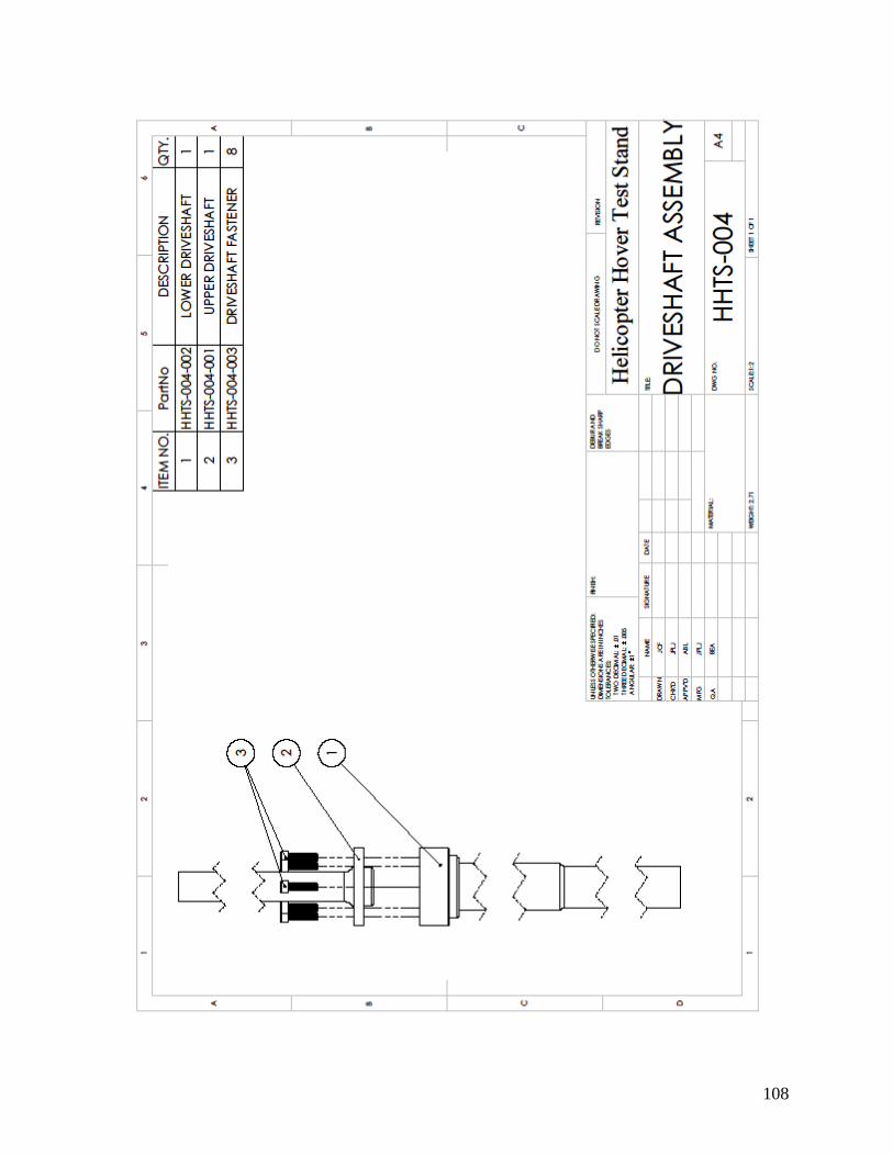
108
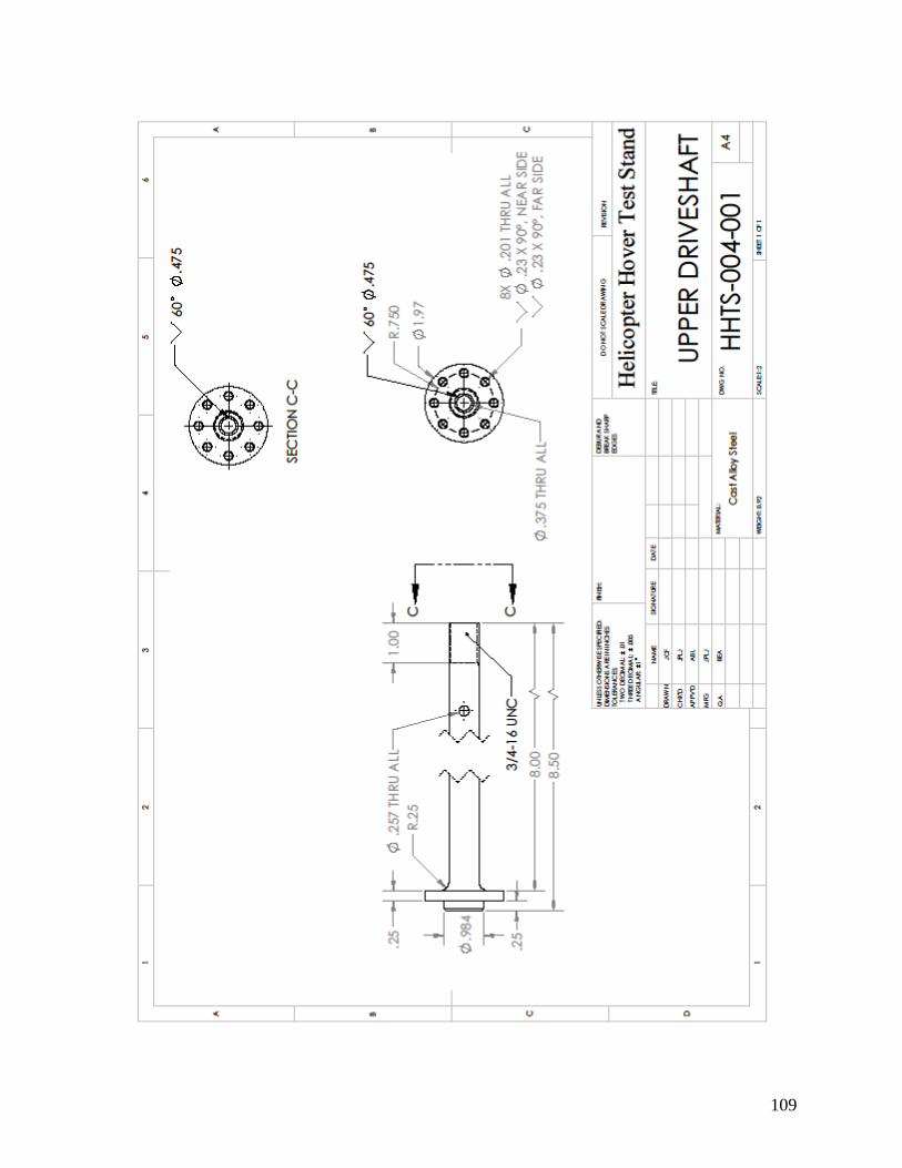
109
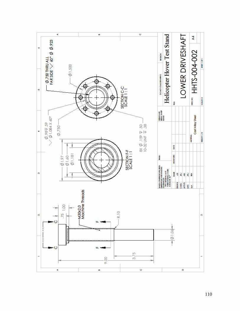
110

111
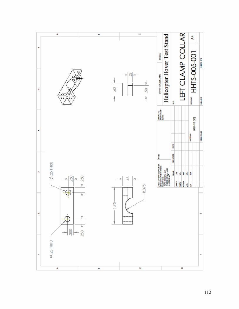
112
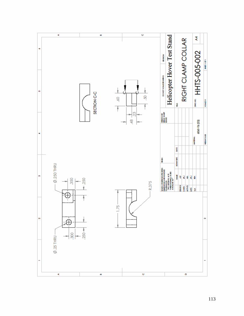
113
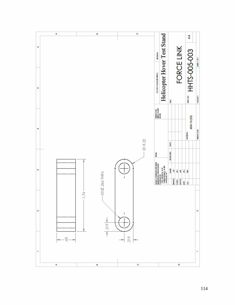
114

115
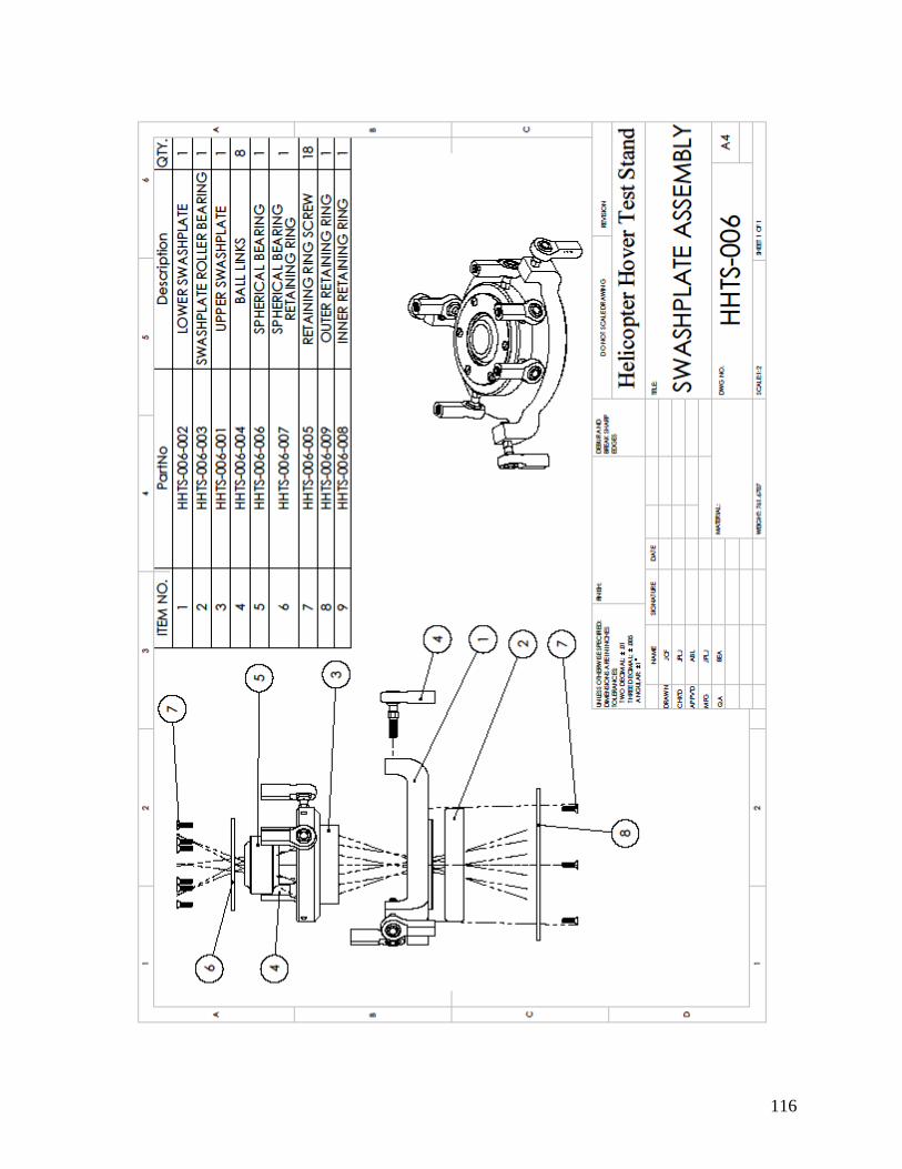
116

117

118

119

120

121

122

123

124

125
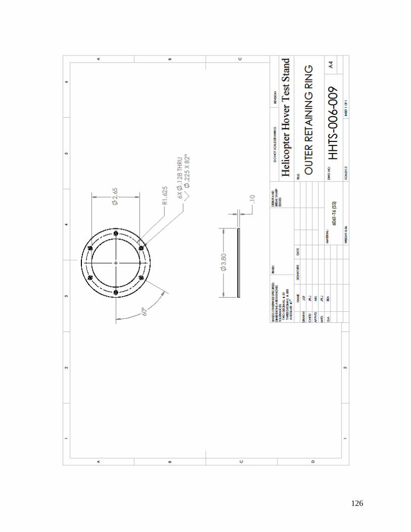
126

127

128

129
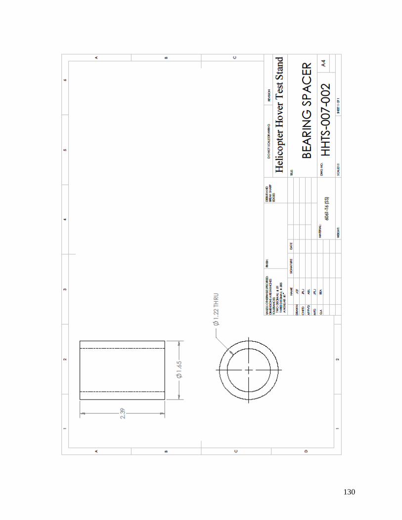
130
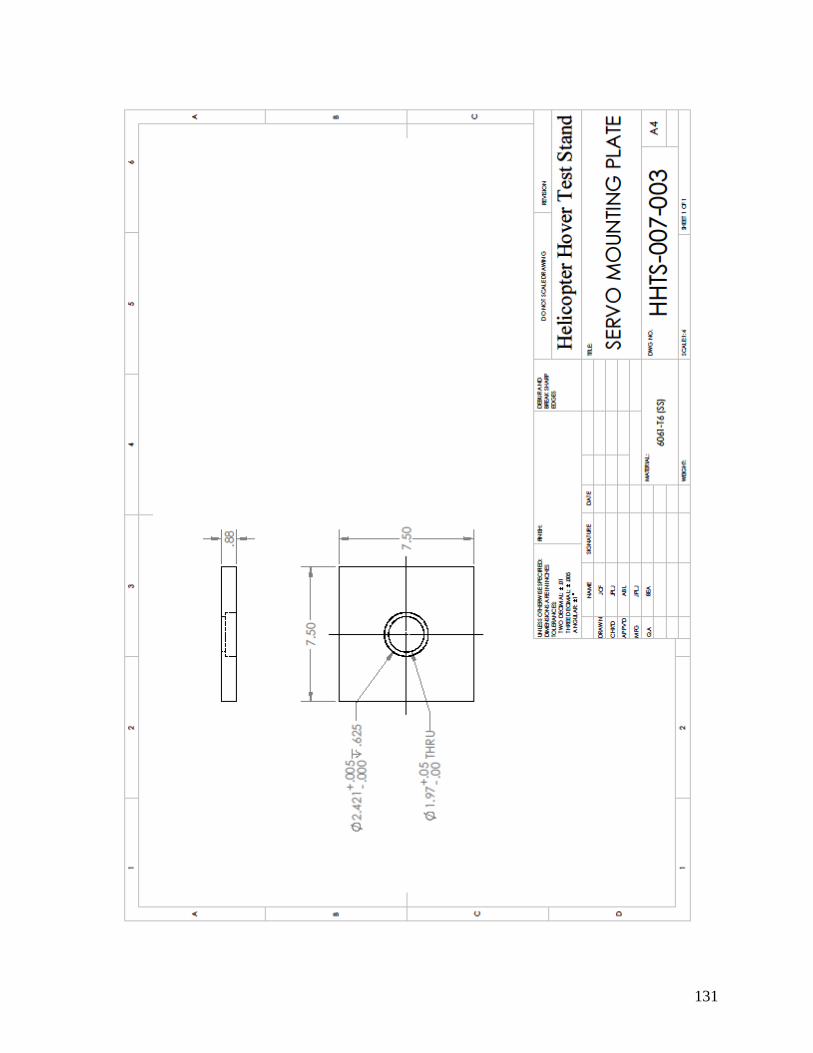
131
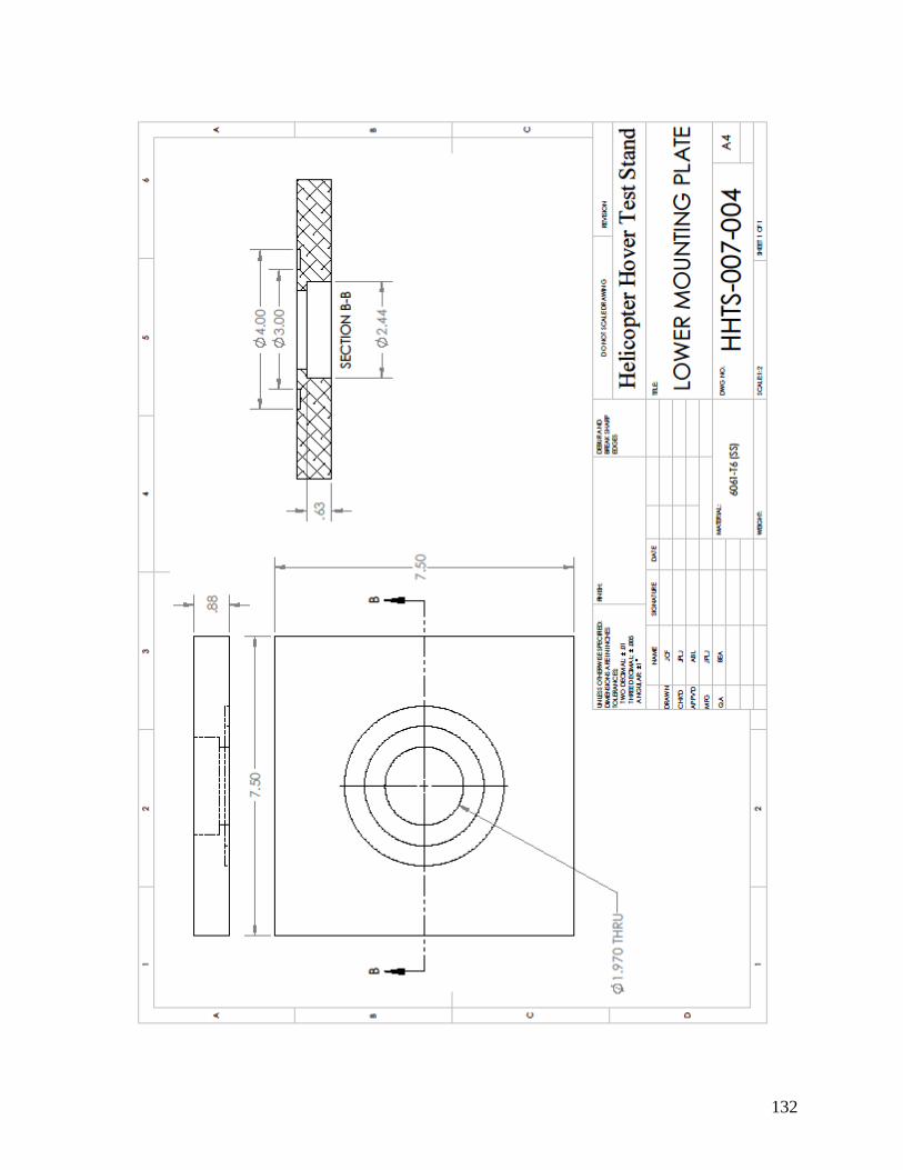
132

133

134

135

136
Appendix B
Process Documentation Sheets

137
Qty
OP # Accept Pending NCR # Initial
10
Qty
4
8
4
12
OP # Accept Pending NCR # Initial
20
Qty
4
8
4
A/R
OP # Accept Pending NCR # Initial
30
Notes
Helicopter Hover Test Stand 2015: Manufacturing Plan
Created by Jonathan LabrieName Bearing Housing Assembly
Date 10/13/2014
Material Al 6061 T6Part # HHTS-001
Document Rev. A 4
Operation Completed Date
Assembly, Bearings
HTTS-001-001
Assembly, Control
Thrust Bearing
HTTS-001-003
HTTS-001-003
Part #
Operation Release Date
Part #
HTTS-001-002
HTTS-001-006
Part Name
HTTS-001-003
Bearing Housing
Part Name
Control Arm
Roller Bearing
Bearing Washer
HTTS-001-007 Ball Linkage
#4-40, 3/4"
Operation Release Date
QA RELEASE
HTTS-001-008 Expoxy Bond Coat

138
Qty
OP # Accept Pending NCR # Initial
10 5 0 - JPL
OP # Accept Pending NCR # Initial
20 5 0 - JPL
OP # Accept Pending NCR # Initial
30 5 0 - JPLJ
OP # Accept Pending NCR # Initial
40
OP # Accept Pending NCR # Initial
50
OP # Accept Pending NCR # Initial
60
OP # Accept Pending NCR # Initial
70
Operation Completed Date
CNC Mill
Helicopter Hover Test Stand 2015: Manufacturing Plan
Created by Jonathan LabrieName Bearing Housing
Date 10/28/2014
Material Al 6061 T6Part # HHTS-001-001
Stock 2.5" OD x 24"
Document Rev. A 1
Operation Completed Date
Operation Completed Date
CNC Mill 11/12/2014
Manual Lathe 10/31/2014
Operation Completed Date
Manual Lathe 10/31/2014
Operation Completed Date
Tapping
Operation Completed Date
Deburring/Finishing
Operation Completed Date
Component
Notes

139
Manufacturing Operation Sheets

140
Machine
Tool #
-
-
-
-
-
Helicopter Hover Test Stand 2015: Operation SheetOP# 10
Manual Lathe
Created by Jonathan LabrieName Bearing Housing
Date 10/26/2014
Material Al 6061 T6Part # HHTS-001-001
Stock 2.25 Dia. x 24"
Part Rev. A Manual Lathe (Chuck)
Manually turn OD, Drill thru, Bore pocket, cutoff
Description Notes
OD turning insert Face end, Finish OD
Spot drill Spot .500 hole
1/2" Drill Drill Thru
7/8" SQ EndMill Bore .875 diameter .600 deep
Cut off tool Cut part to rough length
Notes

141
Machine
Tool #
-
-
Helicopter Hover Test Stand 2015: Operation SheetOP# 20
Manual Lathe
Created by Jonathan LabrieName Bearing Housing
Date 10/26/2014
Material Al 6061 T6Part # HHTS-001-001
Stock In Process
Part Rev. A Manual Lathe (Chuck)
Manually face end, Bore pocket.
Description Notes
OD turning insert Face end, Finish OD
7/8" SQ EndMill Bore .875 diameter .300 deep
Notes

142
Machine
Tool # min LOC min OOH Comp
1 0.18 1.00 yes
2 1.25 2.00 no
3 0.5 1.00 yes
Helicopter Hover Test Stand 2015: Operation SheetOP# 30
Manual Mill
Created by Jonathan LabrieName Bearing Housing
Date 10/31/2014
Material Al 6061 T6Part # HHTS-001-001
Stock In Process
Part Rev. A Manual Mill
Program number O3014 Programmed by Jonathan Labrie
3/8" Drill Mill, 90 deg, 2 fl Spot Holes, 8 places
#43 Drill (.089)
Description Notes
Drill for 4-40 tap, 8 places
Work coordinate G54 File Name HHTS-001-001 OP 30.esp
Set up Set origin x center, y positive, z0 Top. Deep bore toward y negative
3/8 SQ End Mill Mill flat
Notes

143
Machine
Tool # min LOC min OOH Comp
1 0.18 1.00 yes
2 1.25 2.00 no
Helicopter Hover Test Stand 2015: Operation SheetOP# 40
CNC Mill
Created by Jonathan LabrieName Bearing Housing
Date 10/31/2014
Material Al 6061 T6Part # HHTS-001-001
Stock In Process
Part Rev. A Haas MiniMill
Program number O3015 Programmed by Jonathan Labrie
#43 Drill (.089) Drill for 4-40 tap, 8 places
Work coordinate G54 File Name HHTS-001-001 OP 40.esp
Set upSet origin x y center, z0 Top.
Hold with flat facing y positive. Will tap manually in OP#50
Description Notes
3/8" Drill Mill, 90 deg, 2 fl Spot Holes, 8 places
Notes

144
Appendix C
Operation Manual
Safety
Operator Requirements:
If proper precaution and preventative safety measures are not taken, this device may cause
serious injury or death. Any operator of the device must meet the following criteria:
1. Must have read and understood the operator manual
2. Must wear safety glasses
3. Must have completed operator checklist before operation
Operator Responsibilities:
1. Follow and enforce all safety procedures and precautions
2. Contact WPI campus police/EMS immediately in the event of any serious injury
3. Leave the device in a safe, secure, and unpowered situation when leaving the device
unattended
Second user:
A second person must accompany the operator whenever power to the Helicopter Hover Test
Stand is turned on. This second person must meet the following criteria:
1. Must give a verbal exchange that they are the second for the operator
2. Must remain in sight of the Helicopter Hover Test Stand at all times
3. Must read and understood the Helicopter Hover Test Stand operator manual
4. Must wear safety glasses

145
Structural Safety Inspection
Without taking proper safety precautions, operation of this device may cause serious injury or
death. The structural integrity of the system plays a large role in the system. Should a component
fail, it may eject itself at high speed, possibly causing serious injury. Any such failure may also
cause a large imbalance of the rotating system, leading to catastrophic damage. The Structural
Safety Inspection is designed to detect and prevent serious structural failures and deficiencies.
IMPORTANT: Ensure that power to the test stand has been disconnected before inspection.
In order to ensure safe operation inspect the following items BEFORE EACH USE:
1. Blades
a. Inspect for cracks or damage
b. Ensure proper installation in blade grip
2. Rotor Hub
a. Pins are installed correctly and secured with lock wire
b. Hinges move freely and are clear of obstructions
3. Drive shaft
a. Inspect for cracks or other damage
b. Position of nut on top of rotor hub
4. Safety Enclosure
a. Inspect for cracks or other damage
b. Ensure proper installation, no gaps or holes
In order to ensure safe operation inspect the following items once per academic quarter:
1. Warnings and labels
a. All warnings and labels have not been removed, are intact and legible
2. Drive system
a. Belt is correctly tensioned
b. Belt is not cracked or hardened
c. Motor fan is clear of dust and debris
3. Frame and support
a. Stand welds are intact with no cracks
b. Drive shaft support bearings spin freely
c. Frame is level and base has not shifted
4. Electrical
a. Wiring is properly shielded: no cuts or abrasions in protective coverings
b. Variable frequency drive is clear of dust and debris

146
Appendix D
Stress Concentration Graphs
Stress concentration factor graphs are used for the calculation of the stress on the drive shaft base
fillet. The following graphs are taken from Peterson’s Stress Concentration Factors, Second
Edition. Walter D. Pilkey, 1997, John Wiley & Sons, Inc., New York, pgs 157, 164, 166, 168.

147

148

149
1.2

150
Appendix E
Power Calculation using Momentum Theory
% NACA 0012 Airfoil
clc, clear all, close all
% Blade characteristics
R = 0.6; % rotor radius, m
er = 0.1211; % dist from axis to blade, m
c = 0.06; % chord length, m
% Constants (NACA 0012 Airfoil)
alpha_max = 12 ;% Degrees
Cl_al_max = 2*pi*alpha_max*pi/180 ;% Coefficient of lift at max alpha
C_d = 0.02 ;% Blade drag coefficient at zero lift
k = 1.25 ;% Induced power factor (1.15-1.25)
rho = 1.2 ;% Flow density, kg/m^3
% Design Parameters
V = 1250; %RPM
N = 4; %number of blades
% Efficiencies
EF_sys = .95;
Calculations
sigma = (N.*(R-er).*c)/(pi.*(R^2)); %rotor solidarity
A = (pi.*R^2) ; %disk area, m^2
ohm = V.*(2.*pi)/60 ; %angular velocity, rad/s
% Thrust calculations
Lpb = 0.5*rho*Cl_al_max*ohm^2*c*(1/4*(R^4-er^4)-1/3*er*(R^3-er^3));
T_tot = N*Lpb ; %total thrust, N
Watts = ((k.*T_tot.^(3/2))/sqrt(2.*rho.*A) + rho.*A.*((ohm.*R).^3).*(.125.*sigma.*C_d)); %watts
Ideal_Horsepower = Watts/746;
%Efficiency Losses
Min_Horsepower = Ideal_Horsepower/EF_sys;
disp('Ideal Horsepower')
disp(Ideal_Horsepower)

151
disp('Minimum Horsepower')
disp(Min_Horsepower)
Ideal Horsepower
0.9104
Minimum Horsepower
0.9584
Published with MATLAB® R2014a
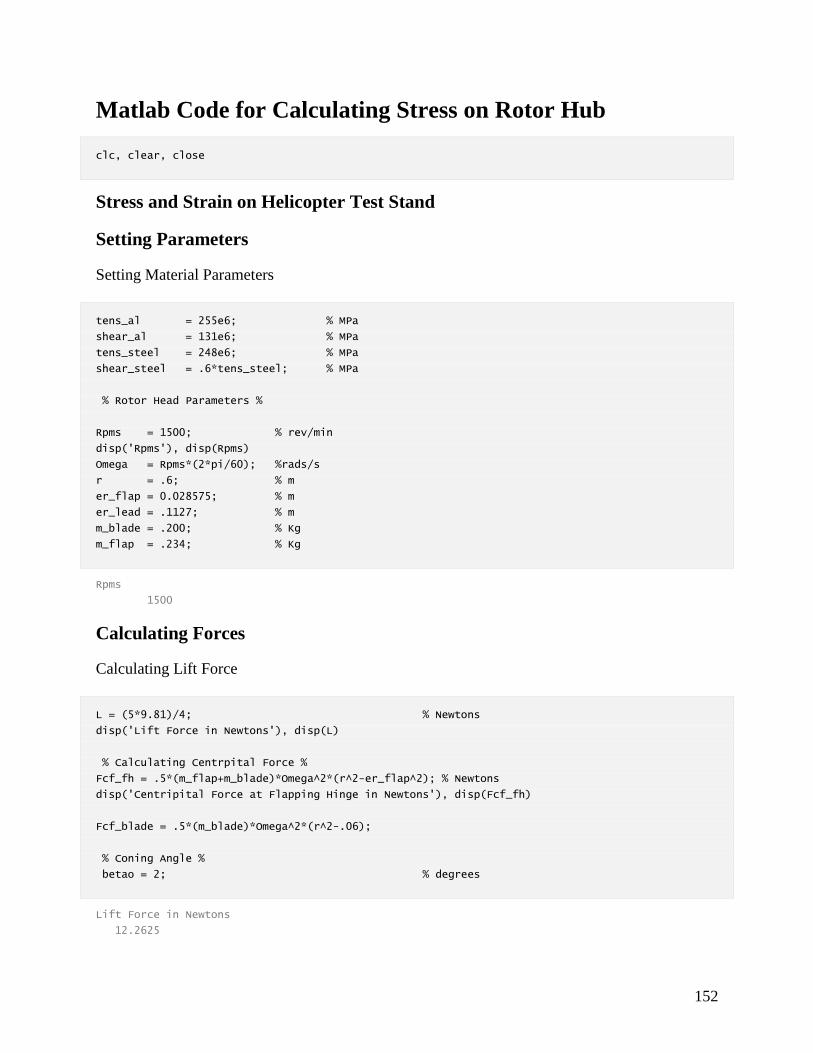
152
Matlab Code for Calculating Stress on Rotor Hub
clc, clear, close
Stress and Strain on Helicopter Test Stand
Setting Parameters
Setting Material Parameters
tens_al = 255e6; % MPa
shear_al = 131e6; % MPa
tens_steel = 248e6; % MPa
shear_steel = .6*tens_steel; % MPa
% Rotor Head Parameters %
Rpms = 1500; % rev/min
disp('Rpms'), disp(Rpms)
Omega = Rpms*(2*pi/60); %rads/s
r = .6; % m
er_flap = 0.028575; % m
er_lead = .1127; % m
m_blade = .200; % Kg
m_flap = .234; % Kg
Rpms
1500
Calculating Forces
Calculating Lift Force
L = (5*9.81)/4; % Newtons
disp('Lift Force in Newtons'), disp(L)
% Calculating Centrpital Force %
Fcf_fh = .5*(m_flap+m_blade)*Omega^2*(r^2-er_flap^2); % Newtons
disp('Centripital Force at Flapping Hinge in Newtons'), disp(Fcf_fh)
Fcf_blade = .5*(m_blade)*Omega^2*(r^2-.06);
% Coning Angle %
betao = 2; % degrees
Lift Force in Newtons
12.2625

153
Centripital Force at Flapping Hinge in Newtons
1.9232e+03
Calculating force on the flapping hinge
Force on HHTS-003-002
Fmax_HHTS_003_002 = 2*pi*(0.003175^2)*shear_steel;
disp('Max force on HHTS-003-002 in Newtons'), disp(Fmax_HHTS_003_002)
F_on_HHTS_003_002 = sqrt(Fcf_fh^2+L^2);
disp('Force on HHTS-003-002 in Newtons'), disp(F_on_HHTS_003_002)
SF_HHTS_003_002 = Fmax_HHTS_003_002/F_on_HHTS_003_002;
% disp('Safety factor for HHTS-003-002'), disp(SF_HHTS_003_002)
% Force on HHTS-003-001
Fmax_HHTS_003_001 = 2*tens_al*.00635*.01016;
disp('Max force on HHTS-003-001 in Newtons'), disp(Fmax_HHTS_003_001)
F_on_HHTS_003_001 = F_on_HHTS_003_002;
% disp('Force on HHTS-003-001 in Newtons'), disp(F_on_HHTS_003_001)
SF_HHTS_003_001 = Fmax_HHTS_003_001/F_on_HHTS_003_001;
% disp('Safety factor for HHTS-003-001'), disp(SF_HHTS_003_001)
% Force on HHTS-002-001 at HHTS-003-002
Fmax_HHTS_002_001 = tens_al*.003175*.0127;
disp('Max force on HHTS-002-001 in Newtons'), disp(Fmax_HHTS_002_001)
F_on_HHTS_002_001 = F_on_HHTS_003_002;
% disp('Force on HHTS-002-001 in Newtons at HHTS-003-002'), disp(F_on_HHTS_002_001)
SF_HHTS_002_001 = Fmax_HHTS_002_001/F_on_HHTS_002_001;
% disp('Safety factor for HHTS-002-001 at HHTS-003-002'), disp(SF_HHTS_002_001)
Max force on HHTS-003-002 in Newtons
9.4248e+03
Force on HHTS-003-002 in Newtons
1.9232e+03
Max force on HHTS-003-001 in Newtons
3.2903e+04
Max force on HHTS-002-001 in Newtons
1.0282e+04
Calculating Force on HHTS_002_006
Force on HHTS-002-006
Fmax_HHTS_002_006 = tens_steel*2*pi*.00198^2;
disp('Max force on HHTS-002-006 in Newtons'), disp(Fmax_HHTS_002_006)
F_on_HHTS_002_006 = F_on_HHTS_003_002;
% disp('Force on HHTS-002-006 in Newtons'), disp(F_on_HHTS_002_006)

154
SF_HHTS_002_006 = Fmax_HHTS_002_006/F_on_HHTS_002_006;
% disp('Safety factor for HHTS-002-006'), disp(SF_HHTS_002_006)
% Force on HHTS_002_003 at pin hole
Fmax_HHTS_002_003_atpinhole = tens_steel*2*.00198*.0095;
disp('Max Force on HHTS-002-003 at HHTS-002-006'), disp(Fmax_HHTS_002_003_atpinhole)
F_on_HHTS_002_003_atpinhole = F_on_HHTS_003_002;
% disp('Force on HHTS-002-003 at HHTS-002-006'), disp(F_on_HHTS_002_003_atpinhole)
SF_HHTS_002_003_atpinhole = Fmax_HHTS_002_003_atpinhole/F_on_HHTS_002_003_atpinhole;
% disp('Safety factor for HHTS-002-003 at HHTS-002-006'), disp(SF_HHTS_002_003_atpinhole)
% Force on HHTS-002-001 at HHTS-002-006
Fmax_HHTS_002_001_atpinhole = tens_al*2*.00198*.00476*2;
disp('Max Force on HHTS-002-001 at HHTS-002-006'), disp(Fmax_HHTS_002_001_atpinhole)
F_on_HHTS_002_001_atpinhole = F_on_HHTS_003_002;
% disp('Force on HHTS-002-001 at HHTS-002-006'), disp(F_on_HHTS_002_001_atpinhole)
SF_HHTS_002_001_atpinhole = Fmax_HHTS_002_001_atpinhole/F_on_HHTS_002_001_atpinhole;
% disp('Safety factor for HHTS-002-001 at HHTS-002-006'), disp(SF_HHTS_002_001_atpinhole)
% Force on HHTS-002-003 at head
Fmax_HHTS_002_003_athead = 7.1255e-5*tens_steel;
disp('Max Force on HHTS-002-002 at its head'), disp(Fmax_HHTS_002_003_athead)
F_on_HHTS_002_003_athead = F_on_HHTS_003_002;
% disp('Force on HHTS-002-003 at at its head'), disp(F_on_HHTS_002_003_athead)
SF_HHTS_002_003_athead = Fmax_HHTS_002_003_athead/F_on_HHTS_002_003_athead;
% disp('Safety factor for HHTS-002-003 at its head'), disp(SF_HHTS_002_003_athead)
Max force on HHTS-002-006 in Newtons
6.1089e+03
Max Force on HHTS-002-003 at HHTS-002-006
9.3298e+03
Max Force on HHTS-002-001 at HHTS-002-006
9.6133e+03
Max Force on HHTS-002-002 at its head
1.7671e+04
Calculating Force on HHTS-001-006 at HTTS-002-002
Force on HHTS-001-006
Fmax_HHTS_001_006 = tens_steel*8*.1257/(100*100);
disp('Max Force on HHTS-001-006 at HHTS-002-002'), disp(Fmax_HHTS_001_006)
F_on_HHTS_001_006 = F_on_HHTS_003_002;
% disp('Force on HHTS-001-006 at HHTS-002-002'), disp(F_on_HHTS_001_006)
SF_HHTS_001_006 = Fmax_HHTS_001_006/F_on_HHTS_001_006;
% disp('Safety factor for HHTS-001-006 at HHTS-002-002'), disp(SF_HHTS_001_006)
% Force HHTS-002-002 at 001
Fmax_HHTS_002_002_at001 = 8*tens_al*.00556*.00635;
disp('Max Force on HHTS-002-002 at HHTS-001-006'), disp(Fmax_HHTS_002_002_at001)
F_on_HHTS_002_002_at001 = F_on_HHTS_003_002;

155
% disp('Force on HHTS-002-002 at HHTS-001-006'), disp(F_on_HHTS_002_002_at001)
SF_HHTS_002_002_at001 = Fmax_HHTS_002_002_at001/F_on_HHTS_002_002_at001;
% disp('Safety factor for HHTS-002-002 at HHTS-001-006'), disp(SF_HHTS_002_002_at001)
Max Force on HHTS-001-006 at HHTS-002-002
2.4939e+04
Max Force on HHTS-002-002 at HHTS-001-006
7.2024e+04
Calculating interior Shear on HHTS-001-001
Force on HHTS-001-001
Fmax_HHTS_001_001 = .02223*.00318*shear_al;
disp('Max Force on interior HHTS-001-001'), disp(Fmax_HHTS_001_001)
F_on_HHTS_001_001 = F_on_HHTS_003_002;
% disp('Force on HHTS-001-001'), disp(F_on_HHTS_001_001)
SF_HHTS_001_001 = Fmax_HHTS_001_001/F_on_HHTS_001_001;
%disp('Safety factor for HHTS-001-001'), disp(SF_HHTS_001_001)
Max Force on interior HHTS-001-001
9.2606e+03
Calculating Forces on blade root pin
Force on Blade root pin
Fmax_Bladeroot_pin = (.0028/2)^2*pi*shear_steel*2;
disp('Max Force on Blade Root Pin'), disp(Fmax_Bladeroot_pin)
F_Bladeroot_pin = Fcf_blade*cosd(betao)+L*sind(betao);
% disp('Force on Blade Root Pin'), disp(F_Bladeroot_pin)
SF_Bladeroot_pin = Fmax_Bladeroot_pin/F_Bladeroot_pin;
%disp('Safety factor for Blade Root Pin'), disp(SF_Bladeroot_pin)
% Force on Blade grip pin hole
Fmax_Bladegrip_hole = 2*.0064*.0028*tens_al;
disp('Max Force on Blade Grip Hole'), disp(Fmax_Bladegrip_hole)
F_Bladegrip_hole = F_on_HHTS_003_002;
% disp('Force on Blade Grip Hole'), disp(F_Bladegrip_hole)
SF_Bladegrip_hole = Fmax_Bladegrip_hole/F_Bladegrip_hole;
% disp('Safety factor for Blade Grip Hole'), disp(SF_Bladegrip_hole)
Max Force on Blade Root Pin
1.8325e+03
Max Force on Blade Grip Hole
9.1392e+03

156
Published with MATLAB® R2014a
Matlab Code for Calculating Torsion on the Shaft
%Matlab Code for Calculating Torsion on the Shaft
clear, close, clc
Read_Graphs_Torsion = 'no' ;
Read_Graphs_Tension = 'no' ;
Read_Graphs_Bending = 'no' ;
Display_Fatigue_Calculations = 'yes';
Calculating torsion on the shaft
Input Parameters
c1 = .009525; % m, ID of drive shaft
c0 = .01905; % m, OD of drive shaft
T = 15; % Nm, Torque generted by motor
r = .003175; % m, Off set distance of CG
M = 5; % Kg, Mass of rotor head
omega_RPM = 1500; % Rpm
L = .2286; % m, distance from shaft point to rotor head, 9in
F_Lift = 76.9; % N, Total lift
beta = 3*pi/180; % rad, coning angle
rad = .00635 ;% radius of stress concentration fillet, m
D = .030 ;% diameter of lower drive shaft, m
d = 2*c0 ;
d_i = 2*c1 ;
t = (D-d)/2 ;% edge to edge, m
Direct Torsion due to Engine Torque
output_K_ts = Stress_concentration_torsion(D, d, d_i, rad, Read_Graphs_Torsion);
K_ts = output_K_ts(1);
J = pi/2*(c0^4-c1^4);
tau_max = (T*c0)/J;
tau_maxMPa = tau_max/10^6;
tau_maxMPa_conc = tau_maxMPa*K_ts;

157
Stress due to Rotor Imbalance
output_K_tb = Stress_concentration_bending(D, d, rad, Read_Graphs_Bending);
K_t_bending = output_K_tb(1);
omega_RADS = omega_RPM*2*pi/60;
V = omega_RADS*r;
Fcent = M*V^2/r;
Mimb = Fcent*L;
S_imb = Mimb*c0/J;
S_imbMPa = S_imb/10^6;
S_imbMPa_conc = S_imbMPa*K_t_bending;
Stress due to Lift Dissymmetry
output_K_t = Stress_concentration_tension(D, d, d_i, rad, Read_Graphs_Tension);
K_t_tension = output_K_t(1);
F_Liftz = F_Lift*cos(beta);
M_Liftx = F_Lift*sin(beta)*L;
A = pi*(c0^2-c1^2);
S_Liftmax = M_Liftx*c0/J;
S_LiftmaxMPa = S_Liftmax/10^6;
S_LiftmaxMPa_conc = S_LiftmaxMPa*K_t_bending;
S_Liftz = F_Liftz/A;
S_LiftzMPa = S_Liftz/10^6;
S_LiftzMPa_conc = S_LiftzMPa*K_t_tension;
Overall Stress
S_Max = S_imbMPa_conc + S_LiftzMPa_conc + S_LiftmaxMPa_conc;
S_Min = S_imbMPa_conc + S_LiftzMPa_conc - S_LiftmaxMPa_conc;
SzMax = S_Max;
SzMin = S_Min;
Sy = 0;
tauyz = tau_maxMPa_conc;
Princ_Max = (SzMax+Sy)/2+sqrt(((SzMax-Sy)/2)^2+tauyz);
Princ_Min = (SzMin+Sy)/2+sqrt(((SzMin-Sy)/2)^2+tauyz);
tau_max_in_plane = sqrt(((SzMax/2)^2)-tauyz);
S_rest = -((M*9.8)/A)*10^-6;

158
Overall
clc
disp('Max Torsion due to motor torque in (MPa)'), disp(tau_maxMPa_conc)
disp('Stress due to imbalance on rotor head (MPa)'), disp(S_imbMPa_conc)
disp('Stress in x direction due to lift disymmetry (MPa)'), disp(S_LiftmaxMPa_conc)
disp('Stress in z direction due to lift disymmetry (MPa)'), disp(S_LiftzMPa_conc)
disp('Tau_max_in_plane'), disp(tau_max_in_plane)
disp('Total Max Stress (MPa)'), disp(Princ_Max)
disp('Total Min Stress (MPa)'), disp(Princ_Min)
%Fatigue Calcualations
if strcmp(Display_Fatigue_Calculations,'yes')
Mean_Stress = (Princ_Max+Princ_Min)/2;
disp('Mean Stress (MPa)'), disp(Mean_Stress)
Stress_Amp = (Princ_Max-Princ_Min)/2;
disp('Stress Amplitude (MPa)'), disp(Stress_Amp)
Stress_Amp_start_stop = (Mean_Stress-S_rest)/2;
disp('Stress Amplitude Start/Stop(MPa)'), disp(Stress_Amp_start_stop)
Stress_range = Princ_Max-Princ_Min;
disp('Stress_range'), disp(Stress_range)
Stress_ratio = Princ_Min/Princ_Max;
disp('Stress_ratio'), disp(Stress_ratio)
Stress_range_start_stop = Mean_Stress-S_rest;
disp('Stress_range_start_stop'), disp(Stress_range_start_stop)
Stress_ratio_start_stop = S_rest/Mean_Stress;
disp('Stress_ratio_start_stop'), disp(Stress_ratio_start_stop)
end
Max Torsion due to motor torque in (MPa)
1.6119
Stress due to imbalance on rotor head (MPa)
11.4340
Stress in x direction due to lift disymmetry (MPa)
0.1175
Stress in z direction due to lift disymmetry (MPa)
0.1347

159
Tau_max_in_plane
5.7035
Total Max Stress (MPa)
11.8225
Total Min Stress (MPa)
11.5903
Mean Stress (MPa)
11.7064
Stress Amplitude (MPa)
0.1161
Stress Amplitude Start/Stop(MPa)
5.8818
Stress_range
0.2322
Stress_ratio
0.9804
Stress_range_start_stop
11.7637
Stress_ratio_start_stop
-0.0049
Published with MATLAB® R2014a
Torsion Stress Concentration at base fillet of small drive shaft section
function [output_K_ts] = Stress_concentration_torsion(D, d, d_i, rad, Read_Graphs_Torsion)
% Find K_tso
Graph_read_1 = D/d;
Graph_read_2 = rad/d;
if strcmp(Read_Graphs_Torsion, 'yes')
disp('------ Values for ------')
disp('------ Chart 3.12 ------')
disp('D/d')
disp(Graph_read_1)
disp('r/d')
disp(Graph_read_2)
disp('------ Read K_ts ------')
disp('------ Chart 3.12 ------')
K_tso = input('K_ts = ');

160
else
K_tso = 1.1 ;
end
% Find K_ts
clc
Graph_read_1 = D/d;
Graph_read_2 = rad/d;
Graph_read_3 = d_i/d;
if strcmp(Read_Graphs_Torsion, 'yes')
disp('------ Values for ------')
disp('------ Chart 3.14 ------')
disp('D/d')
disp(Graph_read_1)
disp('r/d')
disp(Graph_read_2)
disp('d_i/d')
disp(Graph_read_3)
disp('-- Read K_ts-1/K_tso-1 --')
disp('------ Chart 3.14 ------')
K_tso_1__K_tso_1 = input('K_ts-1/K_tso-1 = ');
else
K_tso_1__K_tso_1 = .94 ;
end
Final Calculation and Output
K_ts = K_tso_1__K_tso_1*(K_tso-1)+1;
output_K_ts = K_ts;
end
Published with MATLAB® R2014a
Tension Stress Concentration at base fillet of small drive shaft section
function [output_K_ts] = Stress_concentration_tension(D, d, d_i, rad, Read_Graphs_Tension)
% Find K_t
t = (D-d)/2;
h = (d-d_i)/2;
Graph_read_1 = t/h;
Graph_read_2 = t/rad;
if strcmp(Read_Graphs_Tension, 'yes')
disp('------ Values for ------')
disp('------ Chart 3.5 ------')
disp('t/h')

161
disp(Graph_read_1)
disp('t/r')
disp(Graph_read_2)
disp('------ Read K_t ------')
disp('------ Chart 3.5 ------')
K_t_tension = input('K_ts = ');
else
K_t_tension = 1.5 ;
end
Final Calculation and Output
output_K_ts = K_t_tension;
end
Published with MATLAB® R2014a
Bending Stress Concentration at base fillet of small drive shaft section
function [output_K_tb] = Stress_concentration_bending(D, d, rad, Read_Graphs_Bending)
% Find K_tso
Graph_read_1 = D/d;
Graph_read_2 = rad/d;
if strcmp(Read_Graphs_Bending, 'yes')
disp('------ Values for ------')
disp('------ Chart 3.10 ------')
disp('D/d')
disp(Graph_read_1)
disp('r/d')
disp(Graph_read_2)
disp('------ Read K_ts ------')
disp('------ Chart 3.10 ------')
K_t_bending = input('K_ts = ');
else
K_t_bending = 1.3 ;
end
% Area Correction
Final Calculation and Output
output_K_tb = K_t_bending;
end
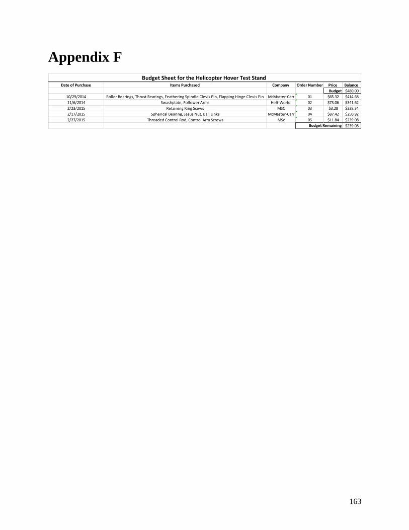
163
Appendix F
Date of Purchase Items Purchased Company Order Number Price Balance
Budget $480.00
10/29/2014 Roller Bearings, Thrust Bearings, Feathering Spindle Clevis Pin, Flapping Hinge Clevis Pin McMaster-Carr 01 $65.32 $414.68
11/6/2014 Swashplate, Follower Arms Heli-World 02 $73.06 $341.62
2/23/2015 Retaining Ring Scews MSC 03 $3.28 $338.34
2/17/2015 Spherical Bearing, Jesus Nut, Ball Links McMaster-Carr 04 $87.42 $250.92
2/27/2015 Threaded Control Rod, Control Arm Screws MSc 05 $11.84 $239.08
$239.08Budget Remaining
Budget Sheet for the Helicopter Hover Test Stand


![3-Momentum Theory in hover 2013 [Modo de Compatibilidade] · Helicopters / Filipe Szolnoky Cunha Momentum Theory in Hover Slide 3 • The main goal of the helicopter is it’s ability](https://img.pdfslide.net/doc/110x75/5d1ff12b88c993ce268df246/3-momentum-theory-in-hover-2013-modo-de-compatibilidade-helicopters-filipe.jpg)


![First-Principles Hover Prediction Using CREATE-AV Helios · – Srinivasan and Sankar [1994], ... Helios Helicopter Overset Simulations High Performance Computing . Runs on HPC hardware](https://img.pdfslide.net/doc/110x75/5ad92f497f8b9a137f8be559/first-principles-hover-prediction-using-create-av-helios-srinivasan-and-sankar.jpg)