Embed Size (px)
Citation preview

ORIGINAL ARTICLE
Design of a Lightweight Soft Robotic Arm Using PneumaticArtificial Muscles and Inflatable Sleeves
Preston Ohta,1 Luis Valle,1 Jonathan King,1 Kevin Low,2 Jaehyun Yi,3,4
Christopher G. Atkeson,1 and Yong-Lae Park1,3,4
Abstract
As robots begin to interact with humans and operate in human environments, safety becomes a major concern.Conventional robots, although reliable and consistent, can cause injury to anyone within its range of motion.Soft robotics, wherein systems are made to be soft and mechanically compliant, are thus a promising alternativedue to their lightweight nature and ability to cushion impacts, but current designs often sacrifice accuracy andusefulness for safety. We, therefore, have developed a bioinspired robotic arm combining elements of rigid andsoft robotics such that it exhibits the positive qualities of both, namely compliance and accuracy, whilemaintaining a low weight. This article describes the design of a robotic arm–wrist–hand system with sevendegrees of freedom (DOFs). The shoulder and elbow each has two DOFs for two perpendicular rotationalmotions on each joint, and the hand has two DOFs for wrist rotations and one DOF for a grasp motion. The armis pneumatically powered using custom-built McKibben type pneumatic artificial muscles, which are inflatedand deflated using binary and proportional valves. The wrist and hand motions are actuated through servo-motors. In addition to the actuators, the arm is equipped with a potentiometer in each joint for detecting jointangle changes. Simulation and experimental results for closed-loop position control are also presented in thearticle.
Keywords: inflatable robot, human-safe robot, assistive robot, bioinspired robot, pneumatic artificial muscle
Introduction
Robots are becoming increasingly relevant and com-mon in day-to-day life, ranging from simple wandering
vacuum cleaners1 to tour guides2,3 and autonomous vehi-cles.4,5 As people continue to find uses for robots, we can onlyexpect to see a continued increase in human–robot interac-tion. Consequently, human and animal safety have become amajor concern around large and/or powerful robotic systemsdue to the generally damaging and unforgiving nature ofcolliding or interfering with one.6 Although collision pre-vention can help reduce the likelihood of an impact, such amethod requires a detailed knowledge of the environment,7,8
which cannot be guaranteed in a human-populated area.Other strategies include introducing mechanical compliancein the arm9,10 and impedance control. Although the safety
level can be increased with the compliance in this case, therealways exists rigidity in the structure that may be still dan-gerous in certain applications. As a result, there has been arecent surge in research directed toward developing andimplementing ‘‘soft robots,’’ wherein systems are designedto be gentle and physically compliant so as to be harmless inthe presence of people or delicate objects.11–15 This ofteninvolves using inflatable structures,16–18 actuator alternativesto the motor,19,20 or force feedback control systems.21,22
With current approaches, however, a common downside tobeing ‘‘soft’’ is also having a very limited load capacity. Forexample, Festo’s Bionic Tripods and Bionic Handling As-sistants, although very lightweight and agile, are depictedmoving objects no heavier than small fruit and three-dimensional (3D)-printed shapes.23–25 Those that are stron-ger, such as Otherlab’s inflatable robots, are often too large
1Robotics Institute, Carnegie Mellon University, Pittsburgh, Pennsylvania.2Department of Mechanical Engineering, Carnegie Mellon University, Pittsburgh, Pennsylvania.3Department of Mechanical and Aerospace Engineering, Seoul National University, Seoul, Korea.4Soft Robotics Research Center, Seoul National University, Seoul, Korea.
SOFT ROBOTICSVolume 00, Number 00, 2017ª Mary Ann Liebert, Inc.DOI: 10.1089/soro.2017.0044
1
Dow
nloa
ded
by S
eoul
Nat
iona
l Uni
v. M
edic
al C
olle
ge f
rom
onl
ine.
liebe
rtpu
b.co
m a
t 10/
12/1
7. F
or p
erso
nal u
se o
nly.
for an in-home domestic robot.26 Another common drawbackis the loss of accuracy in position control due to unaccounteddeformations in the system and/or the inherently underdampednature of a compliant actuation system.27 This can generally becorrected by slowing the system to near-quasistatic loadingscenarios, but at the expense of operating time.
To address this apparent dichotomy between safety andeffectiveness, we developed a bioinspired robotic arm (Fig. 1)that combines soft and rigid systems in a way that resemblesthe human arm in terms of structure, actuation, and degrees offreedom (DOFs). It consists of a lightweight skeleton made ofcarbon fiber composite tubes, 3D-printed rigid plastic joints,on-arm pneumatic artificial muscles (PAMs), and a servo-controlled underactuated hand. An external inflatable sleeveadds to the compliant nature of the air muscles by providing alayer of soft cushioning to dampen impacts.
The internal structure allows for a higher degree of kine-matic accuracy than purely soft systems, and the use oflightweight materials and arm-mounted air muscles rendersthe arm lightweight as a whole and more physically com-pliant than purely rigid systems. Although maximizing forceoutput was not a primary focus of this prototype, the internalstructure also has the benefit of simply being able to addmuscles for increased load capacity at the small sacrifice of afew grams per muscle and a bit of extra tubing. In other arms,increasing joint torque capabilities requires replacing motorsor gear boxes, the approach of simply adding muscles allowsthe user to tune the arm to the required task at will. As a result,
this ‘‘hybridized’’ arm exhibits a combination of propertiesoften found in soft or rigid systems, exclusively.
Similar systems in this vein of research include the dis-tributed macro-mini actuation system,28 which combines arigid external structure with series elastic actuators for coarsemovement, and an integrated motor in each joint for finemovement.29 As a result, it maintained a fair degree of me-chanical compliance while still being accurate. Our system,although similar, diverges from this design so as to confinerigid elements to a simple, compact, and lightweight internalstructure. We also seek to rely entirely on elastic actuators forboth fine and coarse positioning to minimize mass andmaximize safety, and extend our design to a seven DOFssystem.
Taking a bioinspired approach has several other advan-tages. Considering the intended application for such a robot isin a domestic environment, where most tools and utilities arealready optimized for human interaction, a human-like de-sign will allow it to better interface with its surroundings. Inaddition, a robot might be frequently physically interactingwith its human users, so giving it a more organic, relatableappearance and behavior would result in less emotional re-sistance to it, as compared with traditional designs (such asthose of industrial robots).30–32
Design
Arm
One of the main design goals is to develop a robotic armthat can operate safely in the presence of people, while stillbeing relatively strong and precise. In this context, ‘‘safe’’ isdefined as not causing physical harm to a nearby entity, evenin the event of a collision. We approached this goal for therobot arm and hand in two ways: using physically compliantmechanisms for actuation and designing the system withlightweight materials. This reduces the total inertia in thesystem and enables mechanical compliance, both of whichare ideal for a safe robot. As such, in the event of a collision,the arm will deflect and impart a minimal amount of force to aperson or object in its path.
Therefore, we wanted to use an actuator that was bothlightweight and mechanically compliant. Consequently, se-ries elastic actuators were a viable option, as they can exhibitboth of these properties.27 Looking at pneumatic systems,since the compressible nature of air allows for inherentlycompliant systems, we decided to use McKibben-type33–35
air muscles because they are deformable, elastic, and physi-cally lightweight.14,36,37
To minimize mass, we chose materials that had a highstrength-to-weight ratio and that were easy to work with. Forlinks, we used thin-walled carbon fiber rods due to their veryhigh strength-to-weight ratio and suitable precut lengths. Thejoints were made of a 3D-printed lightweight photopolymerwhose mechanical properties are comparable with acryloni-trile butadiene styrene (ABS) plastic. The 3D printingmanufacturing process also had several key benefits, as isdescribed in detail later. Heavy materials such as metal wereavoided except wherein structurally necessary due to size andloading requirements, such as hollow joint pins. Figures 2 and3 show the actual prototype of the robotic arm and its sim-plified diagram with Denavit–Hartenberg (DH) parameters,respectively.
FIG. 1. Robotic arm composed of a lightweight rigidcarbon fiber composite skeleton, soft inflatable sleeves, andPAMs, showing handling of various objects. PAMs, pneu-matic artificial muscles. Color images available online atwww.liebertpub.com/soro
2 OHTA ET AL.D
ownl
oade
d by
Seo
ul N
atio
nal U
niv.
Med
ical
Col
lege
fro
m o
nlin
e.lie
bert
pub.
com
at 1
0/12
/17.
For
per
sona
l use
onl
y.

Joints
To design the joints, we needed to first establish physicalrequirements, such as range of motion. We wanted the armjoints to ideally have a high range of motion, and given thenature of linear actuators, we were limited to the maximumstroke length of the air muscles. We also wanted to keep thedistance from the rotational axis of the joint, which serves asmoment arms for the muscles, constant to maximize torqueoutput from the muscles, and avoids potential mechanicalsingularities. Thus, the arm length, moment length, and rangeof motion are mathematically linked:
C · Lc¼Rh, (1)
LA¼ LC þ 2D: (2)
From these equations and the nature of the muscles wemanufactured, we aimed for a 180� range, resulting in airmuscles with a 25.4 mm contraction region, a link length of305 mm, and a cable curvature of 19 mm. We decided thiswas a reasonably large range that also kept the arm itself frombecoming too large. It also allowed us to make the arm linkscoplanar since we did not need to worry about the links in-terfering with each other.
We wanted to use very few parts per joint to minimizeassembly complexity and weight due to connectors. 3Dprinting was thus ideal because we could print highly com-plex parts as single units, rather than needing to assemblemultiple simpler parts to create an equivalent whole. As such,each joint consists of only two major components: a disk anda fork. During actuation, a disk, attached to the end of a linkby an interface extending from its cylindrical surface, rotatesabout its axis between the two fingers of a supporting fork,which is fixed to a second link. The disk is actuated by a pairof antagonistic air muscles, positioned along the same link asthe fork, through steel cables wound around the disk.
To achieve a 180� range, the cables needed to wrap atleast 180� around the disk, otherwise the cable would ap-proach a singularity, causing the moment length to approachzero and the disk to stop rotating. One possible solution wasto wrap the cables on either side of the extension connectingthe disk to its link, but separating the cables by a largeamount from the joint’s plane of rotation would produce anundesirably large off-axis moment. Instead, we routed thecables side-by-side through the disk itself, as this minimizedthe off-axis moment and could still be manufactured by our3D printer. The first four DOFs in the arm were achieved byprinting two double-linked versions of this joint, whereinthe disk component now consisted of a pair of intersectingdisks offset from each other by 90�, as shown in Figure 2a.
FIG. 2. Image of the robot arm prototype with details of major components. (a) 2 DOFs shoulder and elbow joints.(b) Custom-built PAM and its geometry changes with different actuation pressures. (c) Three-fingered underactuatedrobotic gripper (1 DOF) with its wrist joint (2 DOFs). DOF, degree of freedom. Color images available online at www.liebertpub.com/soro
FIG. 3. Free-body diagramof robot arm design withDenavit–Hartenberg conven-tions, showing two rotationaljoints on each of three joints.
A LIGHTWEIGHT SOFT ROBOTIC ARM 3D
ownl
oade
d by
Seo
ul N
atio
nal U
niv.
Med
ical
Col
lege
fro
m o
nlin
e.lie
bert
pub.
com
at 1
0/12
/17.
For
per
sona
l use
onl
y.
Consequently, two DOFs could be achieved with only threemajor parts.
The joint angles are sensed through a potentiometermounted to each joint. Each disk features a hexagonal holeabout its axis of rotation into which a hexagonal aluminumpin with rounded ends (for smooth rotation about the fork) isinserted, serving as a hinge that rotates relative to the fork butremains fixed relative to the disk. By press-fitting the rotor ofa potentiometer into a hole through the axis of the pin andfastening the potentiometer base to a square housing in thefork, we could determine the angle of each joint by bijec-tively mapping the output voltage from the potentiometer tothe angular position of the disk joint relative to the fork.
To further minimize the overall part count, the musclesactuating a disk joint on one end of an arm link are supportedby mounts on the fork on the opposite end. This is possiblebecause forks mounted on the same arm link are offset by90�, allowing for two pairs of air muscles to be positionedalong each arm link.
The fifth DOF, near the hand, is done by a single-disk jointand actuated by muscles mounted along the forearm. Positioncan again be detected using a potentiometer. The sixth andfinal DOF in the arm, closest to the hand, is a wrist-liketwisting joint actuated by a servo.
Actuators
The arm is actuated by custom-built PAMs, which follow aMcKibben-type design wherein an expanding bladder causesa braided mesh sleeve to contract along its axis. Instead ofusing discrete bladder and mesh components, however, weused a fiberglass-reinforced mesh tube with a layer ofstretchable silicone bonded to the inner surface (Silicone FlexGlass; Techflex, Inc.). The muscles were fabricated by in-serting a pneumatic plug into one end of the tube and anelbow connector inserted through the tube wall on the otherend. These pieces were held in place by metal-reinforced ties.Excess tubing on each end was folded over and tied down toform loops, both of which house a metal split ring onto whicha swaged cable was fastened. Figure 2b shows the actuationbehavior of our pneumatic muscle with different air pres-sures. Muscles were used either singularly or in bundles,depending on the loads experienced at each joint.
Hand
A three-fingered robotic hand was developed and attachedto the lower arm, as shown in Figure 2c. Each finger wasmade of a 3D-printed rigid plastic material covered by softsilicone skin. The actuation of the hand was achieved by atendon-driven underactuated system. An active tendon, lo-cated on the volar side of each finger and connected to a servomotor, induces finger-flexion motion, and an elastic passivetendon on the dorsal side induces finger-extension motion.The fingers also include fiber optic strain sensors for forceand tactile sensing. Details on the hand can be found in ourprevious work.38
Inflatable sleeves
Although the air muscles allow for mechanically compli-ant actuation, an exposed skeletal structure could still resultin high-impact forces if collided with directly, due to its ri-
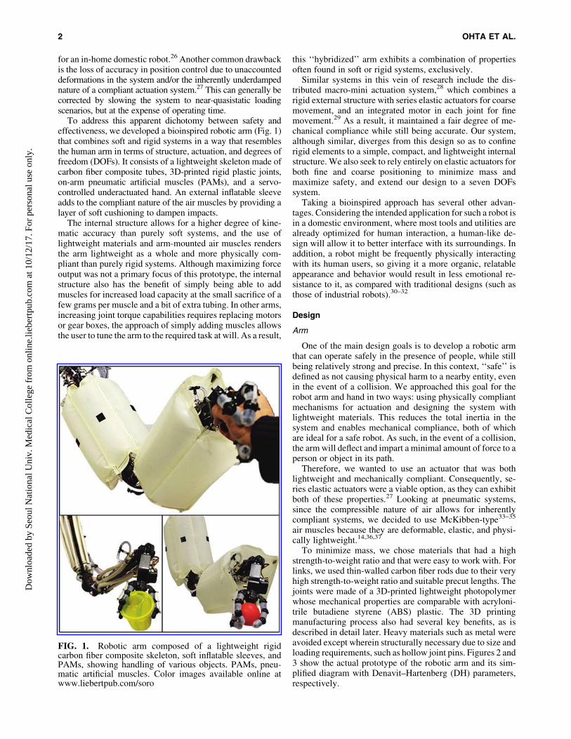
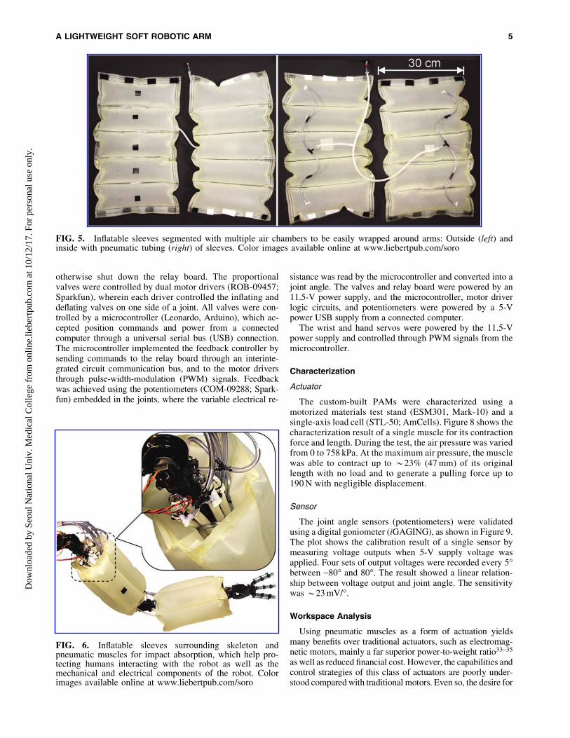
gidity. Soft sleeves comprised polyurethane sheets fusedthrough an impulse heat sealer (MP-40; Midwest Pacific)into inflatable segments (i.e., air chambers), thus envelopedthe structure, as shown in Figure 4. Each sleeve was dividedinto five segments (Fig. 5) to easily form a segmented toroidalstructure around the arm, as shown in Figure 6. The segmentswere pressurized to *20 kPa through a precision pressureregulator (R-800-30; Airtrol Components, Inc.), providing3–5 cm of compressible padding.
Control hardware
For simple actuation, a bank of three-way ON-OFF airvalves (MME-31PES; Clippard) were used to direct airflowinto and out of the muscles. Each valve, when in the ON state,allows pressurized air to flow into a single air muscle, causingit to inflate. In the OFF state, a spring-return mechanismcloses the connection to the inlet and opens the connectionfrom the muscle port to the exhaust, allowing the muscle todeflate. When coupled with air flow reducer valves to lowerthe flow rate and, hence, the rate of muscle inflation anddeflation, this setup allows for position control through asliding mode (SM) controller.
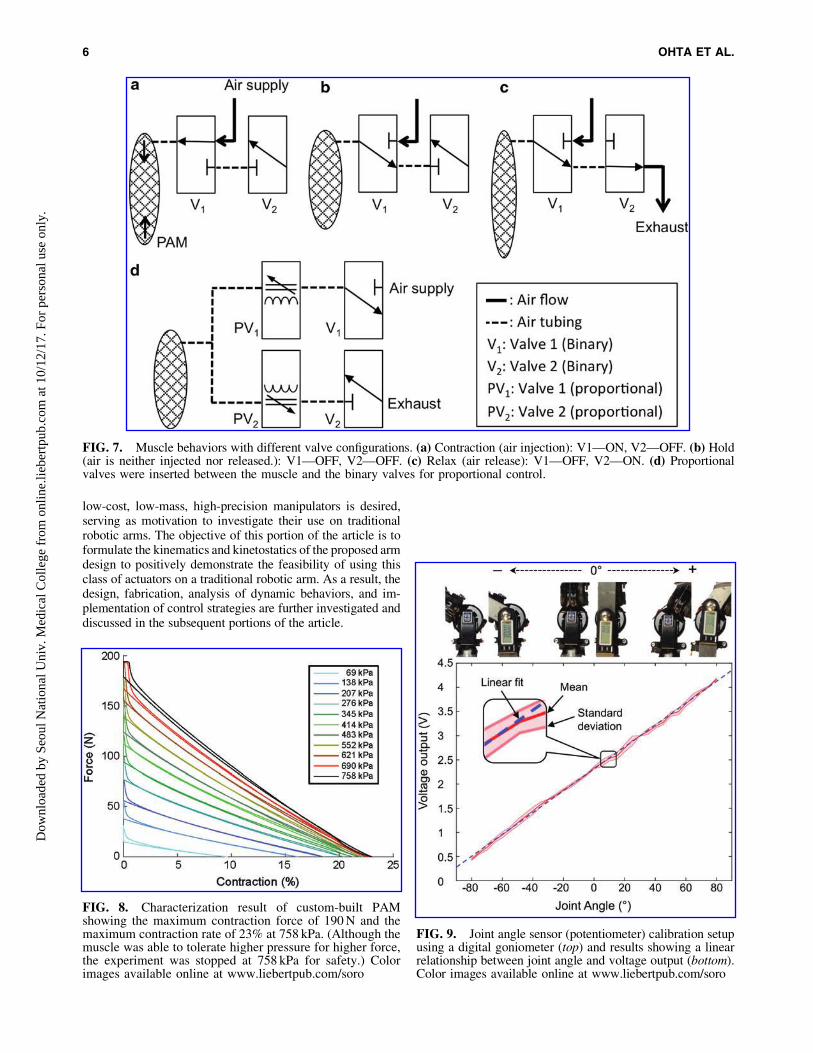
For faster, more stable, and more precise control, a setof pneumatic proportional valves (MD Pro; Parker) wasadded to the system in series with the binary valves. Un-like the binary valves, wherein the valve aperture is onlyeither completely open or completely closed, proportionalvalves can achieve intermediary states as a function of theinput voltage, causing the flow rate of air passing throughthe valve to change accordingly. This allows for the use ofa proportional-integral-derivative (PID) controller to con-trol muscle inflation and deflation. Implementing this typeof control on a pair of antagonistic muscle pairs permitsaccurate positioning of an arm joint. A diagram of theconfiguration of the valves is shown in Figure 7.
The bank of binary valves were controlled through a setof mechanical relays (16 Relay Board), with one relay foreach valve. A diode was inserted across the terminals of thebinary valves to handle the counter-electromotive forceproduced by the actuating valve solenoids, which would
FIG. 4. Arm prototype made of rigid skeleton and pneu-matic muscles before (top) and after (bottom) installinginflatable sleeves. Color images available online at www.liebertpub.com/soro
4 OHTA ET AL.D
ownl
oade
d by
Seo
ul N
atio
nal U
niv.
Med
ical
Col
lege
fro
m o
nlin
e.lie
bert
pub.
com
at 1
0/12
/17.
For
per
sona
l use
onl
y.
otherwise shut down the relay board. The proportionalvalves were controlled by dual motor drivers (ROB-09457;Sparkfun), wherein each driver controlled the inflating anddeflating valves on one side of a joint. All valves were con-trolled by a microcontroller (Leonardo, Arduino), which ac-cepted position commands and power from a connectedcomputer through a universal serial bus (USB) connection.The microcontroller implemented the feedback controller bysending commands to the relay board through an interinte-grated circuit communication bus, and to the motor driversthrough pulse-width-modulation (PWM) signals. Feedbackwas achieved using the potentiometers (COM-09288; Spark-fun) embedded in the joints, where the variable electrical re-
sistance was read by the microcontroller and converted into ajoint angle. The valves and relay board were powered by an11.5-V power supply, and the microcontroller, motor driverlogic circuits, and potentiometers were powered by a 5-Vpower USB supply from a connected computer.
The wrist and hand servos were powered by the 11.5-Vpower supply and controlled through PWM signals from themicrocontroller.
Characterization
Actuator
The custom-built PAMs were characterized using amotorized materials test stand (ESM301, Mark-10) and asingle-axis load cell (STL-50; AmCells). Figure 8 shows thecharacterization result of a single muscle for its contractionforce and length. During the test, the air pressure was variedfrom 0 to 758 kPa. At the maximum air pressure, the musclewas able to contract up to *23% (47 mm) of its originallength with no load and to generate a pulling force up to190 N with negligible displacement.
Sensor
The joint angle sensors (potentiometers) were validatedusing a digital goniometer (iGAGING), as shown in Figure 9.The plot shows the calibration result of a single sensor bymeasuring voltage outputs when 5-V supply voltage wasapplied. Four sets of output voltages were recorded every 5�between -80� and 80�. The result showed a linear relation-ship between voltage output and joint angle. The sensitivitywas *23 mV/�.
Workspace Analysis
Using pneumatic muscles as a form of actuation yieldsmany benefits over traditional actuators, such as electromag-netic motors, mainly a far superior power-to-weight ratio33–35
as well as reduced financial cost. However, the capabilities andcontrol strategies of this class of actuators are poorly under-stood compared with traditional motors. Even so, the desire for
FIG. 5. Inflatable sleeves segmented with multiple air chambers to be easily wrapped around arms: Outside (left) andinside with pneumatic tubing (right) of sleeves. Color images available online at www.liebertpub.com/soro
FIG. 6. Inflatable sleeves surrounding skeleton andpneumatic muscles for impact absorption, which help pro-tecting humans interacting with the robot as well as themechanical and electrical components of the robot. Colorimages available online at www.liebertpub.com/soro
A LIGHTWEIGHT SOFT ROBOTIC ARM 5D
ownl
oade
d by
Seo
ul N
atio
nal U
niv.
Med
ical
Col
lege
fro
m o
nlin
e.lie
bert
pub.
com
at 1
0/12
/17.
For
per
sona
l use
onl
y.
low-cost, low-mass, high-precision manipulators is desired,serving as motivation to investigate their use on traditionalrobotic arms. The objective of this portion of the article is toformulate the kinematics and kinetostatics of the proposed armdesign to positively demonstrate the feasibility of using thisclass of actuators on a traditional robotic arm. As a result, thedesign, fabrication, analysis of dynamic behaviors, and im-plementation of control strategies are further investigated anddiscussed in the subsequent portions of the article.
FIG. 7. Muscle behaviors with different valve configurations. (a) Contraction (air injection): V1—ON, V2—OFF. (b) Hold(air is neither injected nor released.): V1—OFF, V2—OFF. (c) Relax (air release): V1—OFF, V2—ON. (d) Proportionalvalves were inserted between the muscle and the binary valves for proportional control.
FIG. 8. Characterization result of custom-built PAMshowing the maximum contraction force of 190 N and themaximum contraction rate of 23% at 758 kPa. (Although themuscle was able to tolerate higher pressure for higher force,the experiment was stopped at 758 kPa for safety.) Colorimages available online at www.liebertpub.com/soro
FIG. 9. Joint angle sensor (potentiometer) calibration setupusing a digital goniometer (top) and results showing a linearrelationship between joint angle and voltage output (bottom).Color images available online at www.liebertpub.com/soro
6 OHTA ET AL.D
ownl
oade
d by
Seo
ul N
atio
nal U
niv.
Med
ical
Col
lege
fro
m o
nlin
e.lie
bert
pub.
com
at 1
0/12
/17.
For
per
sona
l use
onl
y.

Kinematic representation
The robotic arm (manipulator), represented in Figure 10a,can be kinematically defined by its DH parameters, given inTable 1; the number of muscles actuating each joint, n, is alsoincluded in the table for convenience.
From the DH parameters we can explicitly express the kine-matic mapping, Ti
i+1, between joints as transformations on ho-mogeneous six vectors, ni (i.e., screw displacements or twists):
ni hið Þ¼ 0 0 hi j 0 0 0½ �T 2 se 3ð Þ, (3)
Tiþ 1i nið Þ¼
Riþ 1i tiþ 1
i
01 · 3 1
� �2 SE 3ð Þ, (4)
Riþ 1i ¼
chi� shi
caishi
sai
shichi
cai� chi
sai
0 saicai
24
35 2 SO 3ð Þ, (5)
tiþ 1i ¼ anchi
anshidi½ �T 2 R3: (6)
It is worth to note that the rotation matrix, Rii+1, relating ad-
jacent joints simply defines the principle coordinate axes forthe new coordinate frame relative to the subsequent coordinateframe. Similarly, the translation vector, ti
i+1, locates the newcoordinate frame relative to the subsequent coordinate frame:
Riþ 1i ¼ Xiþ 1
i Y iþ 1i Ziþ 1
i
� �, (7)
tiþ 1i ¼ xiþ 1
i yiþ 1i ziþ 1
i
� �T: (8)
We can compute the kinematic mapping between any twojoints relative to one another using the following relationships:
Tji ¼ Tiþ 1
i Tiþ 2iþ 1 � � � T
jj� 1, (9)
Tji ¼
I4 if i¼ j
Tij
� �� 1
if j > i
(_ (10)
We can apply domain constraints to the joint angles in cor-respondence with their physical joint limits:
h :¼ hijhi 2 � p2
,p2
h i8i 2 1, 2, � � � , 5½ �
n o: (11)
We can then construct the maximum reachable workspace,WSm, of the manipulator with constrained joint limits. Thisis achieved by densely sampling manipulator poses from thejoint angle domain space, and then computing the alpha-shape boundary of the resulting set of end-effector posi-tions. The result is shown in Figure 10b for a sample size of10,000 poses:
qWSm¼ a� Shape t51
��8hi 2 � p2
,p2
h in o� �: (12)
FIG. 10. Workspace analysis results. (a) Sample possibleposes of the robotic arm. (b) Reachable workspace boundarywith joint limits based on kinematic representation. (c) Reach-able workspaces for various payloads based on kinetostaticanalysis. Color images available online at www.liebertpub.com/soro
A LIGHTWEIGHT SOFT ROBOTIC ARM 7D
ownl
oade
d by
Seo
ul N
atio
nal U
niv.
Med
ical
Col
lege
fro
m o
nlin
e.lie
bert
pub.
com
at 1
0/12
/17.
For
per
sona
l use
onl
y.

Kinetostatics
These data in Figure 8 were used to bijectively map themuscle contraction to the maximum muscle force (thisanalysis uses the results for a working pressure of 760 kPa):
fmax Cð Þ : R! R: (13)
Each joint has an identical radius, r, that the muscle tendonsact on. For any manipulator pose defined by h we can com-pute the change in muscle length as:
Dl : ¼ Dl1, Dl2, � � � ,Dl5f g¼ rhij8hi 2 hf g: (14)
Given a constant starting muscle length, l0, the relativechange in muscle length is given as:
Ci¼ Dlil0
C :¼ C1, C2, � � � , C5f g : (15)
Using the relationship between muscle contraction andmaximum applied force given in Equation (13), and the num-ber of muscles actuating each joint, n = {n1, n2, ., n5}, given inTable 1, we can reformulate the mapping to be a function of thejoint angle and as a result construct the set of maximum forcesthat can be applied at each joint for a given pose:
fmax hð Þ : R! R
fmax hð Þ : R5 ! R5
fmax hð Þ¼ l0r
· fmax Cð Þ � nf g, (16)
where · and � are the Cartesian product and Hadamardproduct operators, respectively.
Finally, using the relationship between torque about an axisand a force applied to that axis through an orthogonal lever,s¼ r · f ¼ rf , we can express the ordered set of maximumallowable joint torques for a given pose defined by h:
smax hð Þ : R5 ! R5
smax hð Þ¼ r · fmax hð Þ¼ l0 · fmax Cð Þ � n:(17)
Static joint loads. For any given kinematic mapping, thecorresponding Jacobian is computed through outer productpartial differentiation with respect to the joint angles:
ji J¼
qtji
qhji
Zji
" #2 R6 · j� iþ 1ð Þ, (18)
Zji :¼ Zi
i Ziþ 1i � � � Z
ji
� �2 R3 · j� iþ 1ð Þ: (19)
By the principal of virtual work, the joint torques on a serialmanipulator are given by:
sji¼
ji JT wi, (20)
where wi is the wrench induced on joint i due to the mass oflink i acting through its center-of-mass in the direction of thegravity vector, fi
!¼mi~g. The joint torques for a given poseare given by:
sb hð Þ¼ 51 JT wpayload þ +
5
i¼ 1
ji JT wi 2 R5, (21)
sb hð Þ : ¼ sb,1 sb,2 � � � sb,5½ �T , (22)
where wpayload is the external wrench acting on the end-effector by some payload.
Static reachable workspace. We now know the joint tor-ques for any pose (and any end-effector payload) given byEquation (21), as well as the maximum allowable torques for anypose given by Equation (17). So for the set of poses, we can findthe subsets of poses that satisfy the maximum joint torque con-straints, effectively producing static load reachable workspaces.
The set of feasible poses for a given payload is:
h� wpayload
¼ hjsb,i � smax, i8i 2 1,5½ �f g: (23)
A static workspace, WSs, is the set of reachable positions de-scribed by the set of feasible poses. This is equivalent to the set ofend-effector positions for each pose in the set of feasible poses:
WSspayload ¼ t5
1 h�payload
� �: (24)
Taking the alpha-shape ofWSs produces the boundary ofthe static workspace, which can be easily visualized. Theresults for several payloads are shown in Figure 10c.
The static reachable workspaces for small payloads, al-though certainly not equivalent toWSm, seem to be useable.We can conclude that this type of manipulator is worth in-vestigating further for low payload tasks such as pick-and-place of small parts or personal assistance, such as cookingand administering medication.
Control
Simulation
Based on the result shown in Figure 8, the contraction forceF can be fitted to a function of input air pressure ( p) andcontraction (Dl) as
F¼ 1:14þ 1:87p� 1:90Dl� 0:08pDlþ 0:08Dl2: (25)
For control simulation, the following assumptions wereused for modeling the behavior of the pneumatic muscle:
� Fibers in the muscle are inextensible.� Coulomb friction in the muscle is negligible, resulting
in no hysteresis.� No explicit time dependence is considered.
Table 1. Denavit–Hartenberg Parameters
Link a (cm) a (rad) d (cm) h n
1 3.8 p/2 0 h1 12 40.6 -p/2 0 h2 33 3.8 p/2 0 h3 34 40.6 -p/2 0 h4 25 8.9 0 0 h5 1
8 OHTA ET AL.D
ownl
oade
d by
Seo
ul N
atio
nal U
niv.
Med
ical
Col
lege
fro
m o
nlin
e.lie
bert
pub.
com
at 1
0/12
/17.
For
per
sona
l use
onl
y.

The following assumptions were also used, simulating themechanical system of the arm:
� The arm structure is rigid.� The mass and the inertia of the pneumatic muscles are
negligible.� The reflected inertia by the muscles to the joints is
negligible.� Viscous friction is the only source of friction and
assumed to be linear with respect to joint velocity.� The muscle length is strictly and antagonistically cou-
pled to the angle of its corresponding joint.
Based on the mentioned assumptions, simulation of thedynamic system of the arm was conducted. Two approacheswere used to test the dynamics: an Euler method approachthrough MATLAB and a Runge–Kutta integrator in theODE-45 solver through Simulink.
In the first approach, the screw theory was used to derivethe Euler–Lagrange equations of motion of the five DOFsarm shown in Equation (26). Both methods used the sameequations of motion.
M hð Þ€hþC h, _h� �
_hþG hð ÞþF _h� �¼ s, (26)
F¼ sign Pð Þ 1:14þ 1:87 Pj j � 1:90L� 0:81 Pj jLþ 0:08L2
,
(27)
where h and _h are the actual angle and the angular velocityof the system, respectively. M is the mass tensor matrix, C is thecentripetal Coriolis matrix, G is the gravity vector, F is theviscous friction vector, and s is the torque applied to the system.
We tested three different controllers in simulation: PID, SM,and robust integral of the sign of the error (RISE). We wereinterested in the stability and tracking properties of the system.Theoretically, using Lyapunov analysis in the dynamics ofEquation (26) and without considering feedback linearizationof the torque input, the PID controller is locally stable/track-ing, SM is globally exponentially stable/tracking, and RISE issemiglobal asymptotically stable/tracking.39 The assumptionfor SM is that the actuator used provides infinite frequency,which in practice is impossible. Hence, SM will always yield auniformly ultimately bounded (UUB) result instead of globalexponential tracking. The RISE controller is basically a PIDcontroller combined with some robustness properties of SM,without the disadvantage of the intrinsic discontinuity of SM.To solve this problem, the integral of the SM term is used.
For the simulation we used two metrics. The first one was atracking metric for which step responses at different angleswere tested. The second was the tracking of a sinusoid.
When comparing the step responses of the PID, RISE, andSM controllers in Figure 11a, c, and e, respectively, it can beobserved that the response of the PID and the RISE con-trollers resembles each other. This is because both have asimilar structure. Not a big difference can be observed in thismetric, except for oscillations possibly due to the effects ofthe sign function at angles wherein the actuation bandwidth islimited. The SM step shows a higher rise time and virtuallyno overshoot. The cause of this is the infinite actuator fre-quency assumption of SM. Owing to the quasi-static nature ofour muscle model, the simulation yields an UUB result as
expected. The transient exponential convergence and thechatter at steady state are evidence of this.
When comparing the sinusoid tracking behavior of thePID, RISE, and SM controllers in Figure 11b, d, and f, re-spectively, it can be observed that the PID response and theRISE response again resemble each other. However, thistime, the PID controller does not reach the peaks of the si-nusoid, whereas RISE does. We introduced a time delay tothe SM simulator to compensate for the high frequencycharacteristic of our muscle model. This time, since the resultremained so close to the region of convergence, the undesiredeffects of a UUB result were evident.
An underlying assumption of SM is infinite frequency ofthe actuators. An underlying assumption of the PID controlleris infinite gain. RISE has both assumptions, but the integral ofthe sign of the error was given significantly less gain than therest of the controller. Therefore, the infinite gain assumptiondominates the application of the controller in this system. Insimulation, it is shown that SM has better performance thanPID and RISE. This is because the high frequency assump-tion was more idealized in simulation than the high-gainassumption. For PID, we initially select gains taking thephysical actuation limitation into account. We use theZiegler–Nichols methodology and then fine-tune it to ourparticular case. Hence, degraded performance due to gain isaccounted for. However, for SM, although a delay was in-troduced in the controller, it did not account for certain lags inthe physical system, which would include characterization ofPWM, internal dynamics of the valves, and head loss. Theselosses are more coupled with the frequency of the systemrather than the gain.
Experiments
To understand how the system behaves, we needed toimplement controllers to observe its behavior and determinewhat level of accuracy is achievable with the system. Assuch, our initial tests involved implementing two differentcontrollers: SM and PID. For both controllers, we com-manded one of the arm joints to move to various positions,with the angular displacement being sent from the micro-controller to the connected computer over a USB-serialconnection. The data were time stamped and recorded on thecomputer using RealTerm, a serial terminal program.
In our experiments, a controller that combines the SM andPID controllers was developed, resulting in a fast overallresponse time, relatively high damping, and low steady-stateerror. Over large distances (defined by states in which thecombined results of the proportional and derivative gainsresult in a voltage more than the threshold proportional valvevoltage), a PID controller is utilized until the distance to thetarget is small (when the combined effects of the propor-tional and derivative gains are less than the threshold volt-age), where a SM controller with a low gain is used instead.The SM controller produces a voltage slightly more thanthe threshold voltage, resulting in minimal flow through theproportional valves. In addition, the SM controller does notoperate continuously, but instead pulses the proportionalvalves at a 33% duty cycle as though they were binary valves,further reducing the effective flow rate.
The combined effects of these elements allow the con-troller to converge to its target significantly faster than either
A LIGHTWEIGHT SOFT ROBOTIC ARM 9D
ownl
oade
d by
Seo
ul N
atio
nal U
niv.
Med
ical
Col
lege
fro
m o
nlin
e.lie
bert
pub.
com
at 1
0/12
/17.
For
per
sona
l use
onl
y.

FIG. 11. Simulation results of feedback control. (a) PID multistep response. (b) PID sinusoidal response. (c) RISEmultistep response. (d) RISE sinusoidal response. (e) SM multistep response. (f) SM sinusoidal response. PID, proportional-integral-derivative; RISE, robust integral of the sign of the error; SM, sliding mode. Color images available online at www.liebertpub.com/soro
10 OHTA ET AL.D
ownl
oade
d by
Seo
ul N
atio
nal U
niv.
Med
ical
Col
lege
fro
m o
nlin
e.lie
bert
pub.
com
at 1
0/12
/17.
For
per
sona
l use
onl
y.

the PID or SM controllers alone and with reduced oscilla-tions. Moreover, the pulsed SM reliably corrects steady-stateerror without hunting and often with little or no overshoot.Figure 12 shows the results of control experiments under noload using this third controller.
Conclusion and Future Work
In combining elements of rigid and soft robotics, as well asdesigning lightweight joints with low part counts, the roboticarm addresses many of the drawbacks of rigid and soft sys-tems. Although heavier than purely soft systems, it is stilllightweight for its size (117 cm long and weighing 1.2 kg),mechanically compliant through the use of pneumatic airmuscles and inflatable padding, and accurate by confiningstructural deformations to discrete joints, where they can beeasily and reliably detected.
The arm still has a few drawbacks. In its current configu-ration, it has a relatively low maximum force output, thecontrollers exhibit pseudo-underdamped behaviors, and al-though the arm as a whole is compliant and the padding
covers most of the internal structure, some rigid componentsremain exposed. These are all solvable with our currentsystem, and will be addressed in future work. For example,with a more refined controller and by using more powerful airmuscles (which are currently under development), the armcan be improved in terms of strength, speed, and accuracy.Adding another DOF to the arm would also improve itsability to perform human-like motions, such as pouring waterfrom a bottle, and extending our control over passive tendonsin the hand through the use of shape memory alloys wouldallow for variable elasticity. Once these improvements areimplemented, the arm may possess all of the practical qual-ities necessary for a domestic environment.
Although the controllability of the arm was shown both insimulations and in experiments, it was based on a single jointcontrol. To prove the overall efficacy and practicality of theproposed system, more thorough experiments need to bedone with multijoint control for various positions in a systemlevel. In addition, force control with dynamic motions shouldbe investigated by equipping the arm with multiaxis force–torque sensors in the future.
Another area of future work is control of inflatable sleeveswith embedded soft sensors. The embedded sensors will notonly be able to measure the level of air pressures but alsodetect external contacts. Then, actively controlling the airpressure of the sleeves depending on situations will be pos-sible, which will make the robot more autonomous and in-teractive with environments.
Acknowledgments
This work was supported, in part, by National Aeronauticsand Science Administration (NASA) under Small BusinessInnovation Research (SBIR) Contract NNX14CJ39P and, inpart, by Technology Innovation Program (No. 2017-10069072)funded by the Ministry of Trade, Industry & Energy (MOTIE),Korea, whose support is greatly appreciated.
Author Disclosure Statement
No competing financial interests exist.
References
1. Prassler E, Ritter A, Schaeffer C, Fiorini P. A short historyof cleaning robots. Auton Rob 2000;9:211–226.
2. Burgard W, Cremers AD, Fox D, Hahnel D, Lakemeyer G,Schulz D, et al. Experiences with an interactive museumtour-guide robot. Artif Intell 1999;114:3–55.
3. Diallo AD, Gobee S, Durairajah V. Autonomous tour guiderobot using embedded system control. Procedia Comput Sci2015;76:126–133.
4. Intelligent Unmanned Ground Vehicles: Autonomous Na-vigation Research at Carnegie Mellon. Hebert MH, ThorpeCE, Stentz A. (Eds). New York, NY: Springer Science+-Business Media, 1997.
5. Berger C, Rumpe B. Autonomous driving -5 years after theUrban Challenge: the anticipatory vehicle as a cyber-physicalsystem. In: Proceedings IEEE/ACM International Conferenceon Automated Software Engineering (ASE2012), Essen,Germany, September 2012, pp. 789–798.
6. Bicchi A, Tonietti G. Fast and ‘‘soft-arm’’ tactics. IEEERobot Autom Mag 2004;11:22–33.
FIG. 12. Experimental results of PID-SM combined con-trol showing fast overall response time, relatively highdamping, and low steady-steady error. (a) Multistep re-sponse. (b) Sinusoidal response. Color images availableonline at www.liebertpub.com/soro
A LIGHTWEIGHT SOFT ROBOTIC ARM 11D
ownl
oade
d by
Seo
ul N
atio
nal U
niv.
Med
ical
Col
lege
fro
m o
nlin
e.lie
bert
pub.
com
at 1
0/12
/17.
For
per
sona
l use
onl
y.

7. Khatib O. Real-time obstacle avoidance for manipulatorsand mobile robots. Int J Rob Res 1986;5:90–98.
8. De Santis A, Siciliano B. Safety issues for human-robotcooperation in manufacturing systems. In: ProceedingsTools and Perspectives in Virtual Manufacturing, Napoli,Italy, July 2008.
9. Park JJ, Kim HS, Song JB. Safe robot arm with safe jointmechanism using nonlinear spring system for collisionsafety. In: Proceedings IEEE International ConferenceRobotics and Automation (ICRA’09), Kobe, Japan, May2009, pp. 3371–3376.
10. Yoon SS, Kang S, Yun SK, Kim SJ, Kim YH, Kim M. Safearm design with MR-based passive compliant joints andviscoelastic covering for service robot applications. J MechSci Technol 2004;19:1835–1845.
11. Rus D, Tolley M. Design, fabrication and control of softrobots. Nature 2015;521:467–475.
12. Lipson H. Challenges and opportunities for design, simu-lation, and fabrication of soft robots. Soft Robotics 2012;1:21–27.
13. Park YL, Chen B, Perez-Arancibia B, Young D, Stirling L,Wood RJ, et al. Design and control of a bio-inspired softwearable robotic device for ankle-foot rehabilitation.Bioinspir Biomim 2014;9:016007.
14. Park YL, Chen B, Majidi C, Nagpal R, Goldfield E. Activemodular elastomer sleeve for soft wearable assistance ro-bots. In: Proceedings IEEE/RSJ International ConferenceIntelligent Robots and Systems (IROS’12), Vilamoura,Portugal, September 2012, pp. 1595–1602.
15. Li T, Nakajima K, Calisti M, Laschi C, Pfeifer R. Octopusinspired sensorimotor control of a multi-arm soft robot. In:Proceedings IEEE International Conference Mechatronics andAutomation, Chengdu, China, August 2012, pp. 948–955.
16. Sanan S, Moidel JB, Atkeson CG. Robots with inflatablelinks. In: Proceedings IEEE/RSJ International Conferenceon Intelligent Robots and Systems (IROS’09), St. Louis,MO, October 2009, pp. 4331–4336.
17. Sanan S, Ornstein MH, Atkeson CG. Physical human in-teraction for an inflatable manipulator. In: ProceedingsIEEE International Conference on Engineering Medicineand Biology Society (EMBC’11), Boston, MA, August2011, pp. 7401–7404.
18. Qi R, Lam TL, Xu Y. Kinematic modeling and control of amulti-joint soft inflatable robot arm with cable-drivenmechanism. In: Proceedings IEEE International Conferenceon Robotics and Automation (ICRA’14), Hong Kong,China, May 2014, pp. 4819–4824.
19. Hunter IW, Hollerbach JM, Ballantyne J. A comparativeanalysis of actuator technologies for robotics. Hollerbach J,Craig JJ, Lozano-Perez T. (Eds). The Robotics Review 2.Cambridge, MA: MIT Press, 1992, pp. 299–342.
20. Tonietti G, Schiavi R, Bicchi A. Design and control of avariable stiffness actuator for safe and fast physical human/robot interaction. In: Proceedings IEEE InternationalConference on Robotics and Automation (ICRA’05), Bar-celona, Spain, April 2005, pp.523–531.
21. Tonietti G, Bicchi A. Adaptive simultaneous position andstiffness control for a soft robot arm. In: Proceedings IEEE/RSJ International Conference on Intelligent Robots andSystems (IROS’02), Lausanne, Switzerland, October 2002,Vol. 2, pp. 1992–1997.
22. Albu-Schaffer A, Eiberger O, Grebenstein M, Haddadin S,Ott C, Wimbock T, et al. Soft robotics. IEEE Robot AutomMag 2008;15:20–30.
23. Mahl T, Hildebrandt A, Sawodny O. A variable curvaturecontinuum kinematics for kinematic control of the BionicHandling Assistant. IEEE Trans Rob 2015;30:935–949.
24. Grezesiak A, Becker R, Verl A. The Bionic Handling As-sistant: a success story of additive manufacturing. Assem-bly Autom 2011;31:329–333.
25. Wilson M. Festo drives automation forwards. AssemblyAutom 2011;31:12–16.
26. Sanan S, Lynn PS, Griffith T. Pneumatic torsional actuatorsfor inflatable robots. J Mech Rob 2014;6:031003.
27. Pratt GA, Williamson MM. Series elastic actuators. In:Proceedings IEEE/RSJ International Conference on In-telligent Robots and Systems (IROS’95), Pittsburgh, PA,August 1995, pp. 399–406.
28. Zinn M, Roth B, Khatib O, Salisbury JK. New actuationapproach for human-friendly robot design. Int J Rob Res2004;23:379–398.
29. Shin D, Sardellitti I, Park YL, Khatib O, Cutkosky MR.Design and control of a bio-inspired human-friendly robot.Int J Rob Res 2010;29:571–584.
30. Mori M. The uncanny valley. Energy 1970;7:33–35.31. Duffy BR. Anthropomorphism and the social robot. Rob
Auton Syst 2003;42:177–190.32. Walters ML, Syrdal DS, Dautenhahn K, Boikhorst R, Koay
KL. Avoiding the uncanny valley: robot appearance, person-ality and consistency of behavior in an attention-seeking homescenario for a robot companion. Auton Rob 2008;24:159–178.
33. Chou CP, Hannaford B. Measurement and modeling ofMcKibben pneumatic artificial muscles. IEEE Trans RobAutom 1996;12:90–102.
34. Tondu B. Lopez P. Modeling and control of McKibbenartificial muscle robot actuators. IEEE Control Syst Mag2000;20:15–38.
35. Daerden F, Lefeber D. The concept and design of pleatedpneumatic artificial muscles. Int J Fluid Power 2001;2:41–50.
36. Park YL, Santos J, Galloway K, Goldfield EC, Wood RJ. Asoft wearable robotic device for active knee motions usingflat pneumatic artificial muscles. In: Proceedings IEEEInternational Conference on Robotics and Automation(ICRA’14), Hong Kong, China, May 2014, pp. 4805–4810.
37. Wehner M, Quindan B, Aubin P, Martinez-Villalpando E,Baumann M, Stirling L, et al. A lightweight soft exosuit forgait assistance. In: Proceeding IEEE International Con-ference on Robotics and Automation (ICRA’13), Karls-ruhe, Germany, May 2013, pp. 3347–3354.
38. Jiang L, Low K, Costa J, Black RJ, Park YL. Fiber opticallysensorized multi-fingered robotic hand. In: ProceedingIEEE/RSJ International Conference on Intelligent Robotsand Systems (IROS’15), Hamburg, Germany, September2015, pp. 1763–1768.
39. Patre PM, MacKunis W, Makkar C, Dixon WE. Asymptotictracking for systems with structured and unstructured un-certainties. IEEE Trans Control Syst Technol 2008;16:373–379.
Address correspondence to:Yong-Lae Park
Department of Mechanical and Aerospace EngineeringSeoul National University1 Gwanak-ro, Gwanak-gu
Seoul, 08826Korea
E-mail: [email protected]
12 OHTA ET AL.D
ownl
oade
d by
Seo
ul N
atio
nal U
niv.
Med
ical
Col
lege
fro
m o
nlin
e.lie
bert
pub.
com
at 1
0/12
/17.
For
per
sona
l use
onl
y.