Embed Size (px)
Citation preview

Union CollegeUnion | Digital Works
Honors Theses Student Work
6-2014
Design of a Medical Walker with an IntegratedCrutch MechanismHarrison BourikasUnion College - Schenectady, NY
Follow this and additional works at: https://digitalworks.union.edu/theses
Part of the Equipment and Supplies Commons, and the Geriatrics Commons
This Open Access is brought to you for free and open access by the Student Work at Union | Digital Works. It has been accepted for inclusion in HonorsTheses by an authorized administrator of Union | Digital Works. For more information, please contact [email protected].
Recommended CitationBourikas, Harrison, "Design of a Medical Walker with an Integrated Crutch Mechanism" (2014). Honors Theses. 484.https://digitalworks.union.edu/theses/484

i
Design of a Medical Walker with an Integrated Crutch Mechanism
By
Harrison George Bourikas
* * * * * * * * *
Submitted in partial fulfillment
of the requirements for
Honors in the Department of Mechanical Engineering
UNION COLLEGE
June, 2014

ii
ABSTRACT
BOURIKAS, HARRISON Design of a Medical Walker with an Integrated
Crutch Mechanism. Department of Mechanical Engineering, June 2014.
ADVISOR: William Keat
Many elderly people and injured people suffer from physical complications that
make it difficult or dangerous for them to perform everyday activities, thereby inhibiting
their mobility. Some of these activities include walking, standing, and sitting. As a
result, it is no surprise that many companies in the medical industry have already
attempted to construct an array of options to aid these people, including basic medical
walkers, and standing-assist furniture, poles, and machines. Although these options are
fair choices, they fail to integrate portability, simplicity, and multi-functionality together.
Therefore, this thesis focuses on designing and building a dual purpose machine that can
function as a portable medical walker as well as a standing and sitting aid. The purpose
of this is to increase the mobility of independent and resilient people who struggle to
move around on their own.
A thorough investigation was conducted to determine the natural motion of a
person going from the seated to standing position and vice versa. From that analysis, it
was determined that both the standing and sitting motions were identical, and that the
upper body of a person naturally arced in a manner consistent with a circle. Using the
data acquired from this analysis, the natural upper body motion was replicated by
designing a crutch mechanism/linkage. Then, a walker frame was modeled around the
crutch mechanism. Once the final detailed design was in place, a prototype was
constructed and its range of capabilities was examined.

iii
TABLE OF CONTENTS
Chapter Title Page
I. Introduction ..............................................................................................................1
II. Design Requirements ...............................................................................................6
III. Physical Motion .......................................................................................................8
IV. Detailed Design ......................................................................................................15
a. Overview of the Final Design ..........................................................................15
b. Crutch Design ..................................................................................................18
c. Linkage ............................................................................................................21
d. Construction of the Frame ...............................................................................24
e. Wheel Integration.............................................................................................27
f. Powering Method .............................................................................................30
g. Controls ............................................................................................................35
V. Structural Analysis .................................................................................................40
VI. Prototype Results ...................................................................................................47
a. Evaluation of the Physical Prototype ...............................................................47
b. Results of Human Testing ................................................................................50
VII. Conclusions and Recommendations ......................................................................55
References ..........................................................................................................................58
Appendix 1: Actuator Specifications .................................................................................60
Appendix 2: Vendor List and Comprehensive Bill of Materials .......................................61
Appendix 3: Drawings – Crutches .....................................................................................62
Appendix 4: Drawings – Brackets, Gussets, Plates ...........................................................66

iv
Appendix 5: Drawings – Walker Frame ............................................................................69
Appendix 6: Drawings – Linkage ......................................................................................74
Appendix 7: Drawings – Assembled Walker/Crutch Mechanism .....................................77
Appendix 8: Prototype Evaluation Form ...........................................................................78

1
I. INTRODUCTION
Some elderly people have physical complications that make it difficult/dangerous
for them to sit down or stand up under their own power. Three particular complications
include muscle deterioration, an aging vestibular system, and abnormal blood pressure
regulation. As people get older, some become accustomed to a sedentary lifestyle that
can lead to sarcopenia, which is defined as the loss of roughly ten ounces of muscle a
year [1]. On average, a person will lose around percent of their strength between the
ages of and . As a result of this muscle deterioration and loss of strength, elderly
people can have trouble moving around and performing everyday activities.
Furthermore, an aging vestibular system can cause elderly people to struggle with sitting
down and standing up. The vestibular system is essentially a complex construction of
chambers in the inner ear that are vital to controlling balance [2]. When people reach
years of age, the number of nerve cells in their vestibular system decreases significantly;
this can make it increasingly difficult for an elderly person to maintain their balance.
Likewise, elderly people are more apt to develop postural hypotension, wherein a rapid
drop in blood pressure occurs while sitting or standing, and can ultimately cause
dizziness and faintness [3]. These three reasons illustrate that some elderly people are at
a serious risk when attempting to sit down or stand up.
However, the elderly population is not the only group of people that can
experience a variety of complications when trying to sit down or stand up. Some people
who sustain severe leg or spine injuries may have to relearn how to use their leg muscles
to perform tasks that were once second nature to them. These individuals will need the
support of a walker/harness system to guide and assist them as they regain their mobility.
2
Moreover, nearly million Americans are afflicted with knee osteoarthritis, which occurs
when cartilage in the knee joint slowly erodes [4]. This type of arthritis greatly affects
the mobility of people since the knee can become stiff, swollen, and painful. In some
cases, this medical disability can become severe and ultimately make it difficult to
perform daily activities like walking, sitting, and standing.
It is clear that many people around the world are limited by their lack of mobility
due to physical complications caused by age or injury. Therefore, it is no surprise that
many companies have designed an array of options to aid these resilient people that strive
to be independent and functional. However, most of these options are both awkward and
difficult to use, or are bulky and expensive. In general, there are four main options that
stand out in the current market: (1) standard medical walkers, (2) basic standing-assist
bars/poles (3) costly standing-assist furniture, and (4) medical standing-assist machines
that require the help of an assistant to operate. It is important to note that the first two
options require a person to use their own strength to operate, and the last two options are
complex, bulky, and expensive. An example for each of these four options is presented
in Figure 1 below.
Figure 1: (1) Medical Walker, (2) Standing-Assist Pole, (3) Standing-Assist Chair, (4) Standing-Assist
Machine
4 3 2 1
[5] [6] [7] [8]

3
Each of the four options displayed in Figure 1 have their strengths and
weaknesses, but none of them combine portability, stability, and a mechanized system in
one complete package. In particular, the medical walker is designed with two sets of
handles that are positioned at different levels so that a person can stabilize themselves as
they go from the seated position to the standing position and vice versa. Although the
medical walker is light weight and portable, it requires a person to exploit their own
upper body strength; this could present a serious problem to people that suffer from
severe muscle deterioration. Furthermore, the standing-assist pole can be easily
positioned anywhere in a home, however, it is not portable and can be dangerous since a
person must twist their body awkwardly. The standing-assist chair is another option that
can gradually raise or lower a person via a remote. On the other hand, the chair itself is
extremely heavy, cannot be easily moved around a home, and limits the mobility of a
person since it is not portable. Moreover, standing-assist machines are complex
apparatuses that cannot be operated by a single person. Therefore, these expensive
machines are most often limited to various applications in hospitals or senior living
venues.
After considering the available options for the elderly population and people
affected by limited mobility, it was concluded that a simple, automated, and portable aid
that can provide essential stability features at a reasonable price is needed. The overall
objective for this study is to develop an altered walker frame that can be easily integrated
with a light weight crutch mechanism. Ultimately, this design will be able to support
regular weight transitions from the seated to standing positions and vice versa. The basic
design of the walker/crutch mechanism consists of attaching two crutches to either side of
4
an altered walker frame that is powered by two linear actuators and a battery. Most
importantly, the design will be able to attain duel functionality since it is intended to be
used as a standing/sitting aid and a medical walker that will be employed as a primary
supporting device.
In order to achieve a product with dual functionality, some design restrictions
needed to be established. This process included defining essential aspects of the
walker/crutch mechanism such as: (1) its overall size, (2) its total weight, (3) its stability,
(4) its ergonomic factors, (5) its low key profile, and (6) its ease of use. These six
restrictions put constraints on the design of the walker/crutch mechanism that dictated
which models were feasible options and which models would not be suitable. In
particular, the walker/crutch mechanism needs to fit through an average sized doorway of
, while maintaining a strong frame that is fairly light weight (under lbs) and is
easy to push around. It is also important to note that the design cannot be bulky so that it
does not attract any unwanted attention, and it must take into account ergonomic factors.
But, most importantly the design must include factors of safety so that it will not fail
under unexpected conditions. See section II. Design Requirements for more information.
Furthermore, it was critical to devise a design strategy. Initial research steps were
taken by determining the natural motion of a person sitting down and standing up. Once
that field was explored, various methods for obtaining that motion were developed along
with a way to power the system. After those design concepts were formulated, the
walker frame was designed to fit around the crutch mechanism, and a model was
constructed in SolidWorks. Then, an in depth finite element analysis (FEA) was
performed on the crutches (the most critical components) to examine the overall rigidity

5
of the system. Upon completion of the detailed design, a prototype was constructed to
test its ergonomic factors and its range of capabilities. The following sections outlined in
this design report explain these steps in greater detail.

6
II. DESIGN REQUIREMENTS
During the initial phase of the design process, a set of design requirements were
established so that various aspects of the walker/crutch mechanism could be constrained.
The requirements included addressing (1) overall size, (2) total weight, (3) stability, (4)
ergonomic factors, (5) low key profile, and (6) ease of use. An outline of the
requirements is provided in Table 1:
Table 1: Design requirements for the walker/crutch mechanism
# Major Need Requirement
1 Overall Size
Must fit through an average sized doorway of without
difficulty
Height of the armpit support bar relative to the floor when the
crutch is in its fully retracted position Walker must be wide enough to comfortably accommodate an
average sized person (roughly and lbs)
2 Total Weight Walker must be light enough to be easily portable lbs
3 Stability
All wheels must have breaks
Crutch mechanism must incorporate armpit supports and handles
so that a person can steady themselves if necessary
Must be able to support up to lbs of weight
4 Ergonomics
Motion of the crutch mechanism must be smooth and resemble
the natural arcing upper body motion
Comfortable armpit supports that are adjustable
5 Low Key Profile
Bare-bones so that is does not attract any unwanted attention
Walker cannot be bulky and must be able to be stored easily in a
closet so that it can be out of sight
6 Ease of Use
All wheels must swivel so that it is easier to maneuver
It must be easy to release from the machine
Starting and stopping the mechanism needs to be a tip-of-the-
fingers option (the on/off buttons should be located on the hand
grips)
Using these design requirements as a building block, the design space for the
walker/crutch mechanism was fully defined. It is important to note that the
aforementioned constraints were a way to easily identify viable design options that had
the potential to yield a working prototype. Section IV. Detailed Design of this report will

7
discuss how these design requirements were met and how they were implemented into
the final design of the walker/crutch mechanism.

8
III. PHYSICAL MOTION
The human body is able to move due to contractions of muscles, wherein parts of
the skeleton are allowed to move relative to one another. Anatomical motions can be
classified into various categories, two of which include flexion (the bending of a joint)
and extension (the straightening of a joint) [9]. A healthy person who does not suffer
from physical complications will be able to flex their knee joints to sit down, and extend
their knee joints to stand up. These two anatomical motions explain how the lower body
functions during the sitting and standing processes. However, it is also important to
consider how the upper body moves while sitting and standing from an ergonomics
standpoint. It is not so uncommon for a person to experience excruciating pains in the
lower back, side, or neck regions of the body if they sit down or stand up awkwardly.
Hence, it is vital that the walker/crutch mechanism does not exert any additional stress on
the lower body or upper body of a person using the device.
To ensure that the walker/crutch mechanism is comfortable to use, a study was
performed to determine the natural sitting and standing motions of healthy people. In the
early stages of the design process, it was determined that the crutch mechanism would
engage a person at two main points to provide support, stability, and safety. These two
contact points were identified to be underneath the armpit and at the center of the hand,
much like traditional crutches. In particular, focus was directed on determining the path
of the armpit contact point since it dictated the motion of the upper body. Therefore, it
was concluded that data needed to be acquired at the armpit in order to design a
functional crutch mechanism.

9
Data was obtained by videotaping the sitting and standing motions of two test
subjects. High-speed video at frames per second, regular-speed video, and burst
photos were taken for each sitting and standing motion performed. The video files of
each test were then analyzed using VideoPoint, a video-based motion analysis software
that allows a particular point in space to be tracked through consecutive frames. For each
video file uploaded to the motion analysis software, a scale was set and the origin was
defined at a specific point. Figure 2 shows the scale for the video files, and the
placement of the origin for Test Subject 1 for the sitting to standing motion analyses and
the standing to sitting motion analyses.
Figure 2: (1) Origin location: sitting to standing, (2) Origin location: standing to sitting
It is important to note that the origin was positioned at the same point in space for
every video file regardless of if the test subject was standing up or sitting down. This
was done so that the data points collected in VideoPoint would be consistent for both
motions and yield similar armpit profile curves. It was crucial to collect data with the
2 1

10
origin defined at the same point in space so that the standing and sitting underarm curves
could be assessed.
Armpit profile data was collected for two reasons: (1) to determine the natural
standing and sitting upper body motions of people, and (2) to establish if the natural
standing and sitting motions are similar. It was essential to resolve the latter so that the
walker/crutch mechanism could be designed for its particular function. If the motions
were observed to be similar, then the crutch would only be required to follow one armpit
profile path, which would simplify the design of the crutch/linkage system. The armpit
profile curves for both motions were graphed using MATLab from the discrete points
mapped in VideoPoint; the data for Subject 1 and Subject 2 can be observed in Figures 3
and 4 respectively.
Figure 3: Standing and sitting data for Test Subject 1
-0.7 -0.6 -0.5 -0.4 -0.3 -0.2 -0.1 00
0.1
0.2
0.3
0.4
0.5
0.6
0.7
X-Position (m)
Y-P
ositio
n (
m)
Test Subject 1
Sitting to Standing
Standing to Sitting

11
Figure 4: Standing and sitting data for Test Subject 2
A few important conclusions can be drawn from analyzing the data displayed in
Figures 3 and 4 respectively. Firstly, the data shows that the standing and sitting motions
are, in fact, the same. Second, the motions can be broken down into two separate
components: (1) translating of the shoulders, and (2) upward/downward arcing of the
armpit contact point. The former can be attributed to flexing of the hips and back, which
translates the shoulders over the knees so that a person can shift their center of gravity.
The latter can be attributed to extension of the knees, thereby driving a person upward
into the standing position.
For this particular application, it was assumed that a person can translate their
shoulders without experiencing any complications. Hence, component (1) of the standing
motion was not considered when designing the walker/crutch mechanism in order to
simplify its overall design. As a result, a person will begin in a slightly bent over
position to eliminate the need for the mechanism to translate. Moreover, it was observed
that the armpit contact point arced upwards as a person extended their knee joints, which
was particularly interesting. The motion itself was determined to be that of a circle.
-0.7 -0.6 -0.5 -0.4 -0.3 -0.2 -0.1 00
0.1
0.2
0.3
0.4
0.5
0.6
0.7
X-Position (m)
Y-P
ositio
n (
m)
Test Subject 2
Sitting to Standing
Standing to Sitting
12
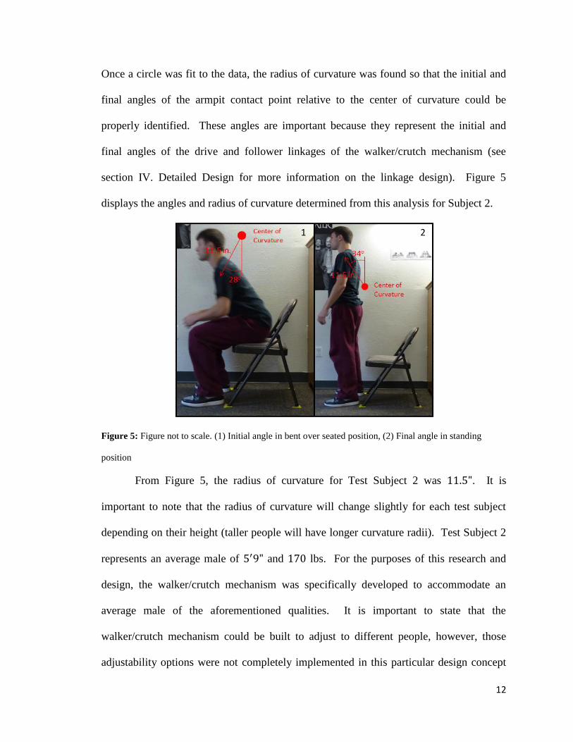
Once a circle was fit to the data, the radius of curvature was found so that the initial and
final angles of the armpit contact point relative to the center of curvature could be
properly identified. These angles are important because they represent the initial and
final angles of the drive and follower linkages of the walker/crutch mechanism (see
section IV. Detailed Design for more information on the linkage design). Figure 5
displays the angles and radius of curvature determined from this analysis for Subject 2.
Figure 5: Figure not to scale. (1) Initial angle in bent over seated position, (2) Final angle in standing
position
From Figure 5, the radius of curvature for Test Subject 2 was . It is
important to note that the radius of curvature will change slightly for each test subject
depending on their height (taller people will have longer curvature radii). Test Subject 2
represents an average male of and lbs. For the purposes of this research and
design, the walker/crutch mechanism was specifically developed to accommodate an
average male of the aforementioned qualities. It is important to state that the
walker/crutch mechanism could be built to adjust to different people, however, those
adjustability options were not completely implemented in this particular design concept
1 2

13
and prototype. Table 2 summarizes the data collected for the test subjects and compares
individual physical features:
Table 2: A summary of the data collected for the natural motion of each test subject
Physical
Features Physical Motion Data
Height Radius of Curvature (in.) Initial Angle Final Angle
Test Subject 1 Test Subject 2
The variation in the radius of curvatures between the two test subjects can be
attributed to their height differences. Ultimately, this implies that the linkages for the
crutch mechanism must be adjustable to accommodate people of different heights.
However, as mentioned before, the walker/crutch mechanism prototype constructed for
this research was not made to be adjustable in order to speed up the building and testing
process. Section IV. Detailed Design discusses the linkage produced to replicate the
natural circular motion examined in this section, and presents some possible adjustability
features that could be implemented.
It is also important to consider how the position of the center of curvature for a
person will shift when they sit in chairs of different heights. If a person sits in a tall
chair, their center of curvature will be located at a higher position with respect to the
floor than if they sit in a short chair. Ultimately, this means that the walker/crutch
mechanism frame must be adjustable up and down to accommodate different chair
heights.
From the data obtained by analyzing the natural upper body motion of people
standing up and sitting down, important information was acquired in order to design an
ergonomic crutch mechanism. Data and/or information acquired included: (1) verifying

14
that the standing and sitting motions are the same, (2) the crutch mechanism will follow a
circular motion, (3) armpit contact point angles in the seated and standing positions, (4)
the radius of curvature. Refer to section IV. Detailed Design for information regarding
the final design.

15
IV. DETAILED DESIGN
a. Overview of the Final Design
An isometric view of the assembled first generation prototype and SolidWorks
model is provided in Figure 6, which indicates the main features of the machine. In
general, raw stock steel was used to construct the components, and a control system
was integrated into the design. The components that were constructed from steel
included: (1) the U-shaped frame, (2) the mounting brackets and support plates, and (3)
the four-bar parallelogram linkages (which guided the crutches along the natural circular
motion). Two linear actuators, a control box, and a lead-acid battery were wired
together in order to provide power to the four-bar linkages. Additionally, total locking
casters were implemented into the design to fully lock the machine in place as it was
being operated.
Figure 6: Isometric views of the prototype and SolidWorks model
Actuator U-Frame Battery Box Caster Support Plate
Crutch Linkage Foam Pad

16
Operation of the walker/crutch mechanism is fairly straightforward. In order to
use the machine, a person can position themselves over the armpit supports and take hold
of the handles. Depending on if a person is initially sitting down or standing up, the
linkages/actuators will be in the fully retracted or extended positions respectively. It is
important to mention that the frame of the walker was designed to be wider than an
average sized chair so that the machine can easily roll up to a seated person. Once a
person has been engaged to the crutches, they can use the machine by pressing the
up/down button on the wireless remote located on the handle, which will activate the two
linear actuators. As the linear actuators extend/retract simultaneously, they will
raise/lower the four-bar parallelogram linkages that were designed to copy the natural
upper body motion of a person. Once the full range of motion has been completed (the
actuators will stop automatically once they have been fully extended/retracted), a person
can easily disengage from the machine by releasing the handles. A person can then
simply roll the machine away from them if they are seated, or continue using it as a
walker in the standing position. Figure 7 illustrates the proper steps to operate the
walker/crutch mechanism:
Figure 7: A test subject using the machine: (1) Seated, (2) Middle, (3) Standing
1 2 3

17
From Figure 7, it can be observed that each of the test subjects must begin in the
slightly bent over position and align their heels with the hand grips. As discussed in
section III. Physical Motion, the test subjects needed to begin in the slightly bent over
position to eliminate the need for the crutch to translate horizontally. Ultimately, this
reduced the complexity of the linkage implemented in the prototype, and it allowed the
mechanism to maintain a low key profile. Also, it was estimated that a test subject would
only be required to bend over at the hips approximately if they situated themselves in
the machine properly. In addition, the motion of the armpit support bar was confirmed to
imitate the natural arcing motion of the armpit contact point, which satisfied the
ergonomics design requirement.
It was important for the test subjects to align their heels with the hand grips on the
crutch so that their center of gravity would stay over their feet as they were being raised
or lowered. In the sequence of photos displayed in Figure 7, it can be observed that the
shoulders of the test subject are always located directly over their feet. This ensured that
the prototype would not shift in any unexpected direction while the machine was being
operated. However, if the test subject felt inclined, they could have engaged the locking
lever breaks on each caster to secure the machine and guarantee that it would not move
out of place.

18
b. Crutch Design
Since the crutch is the interface between a person and the walker/crutch
mechanism, it is the most vital component of the design. It was essential for the crutch to
incorporate ergonomic features so that it did not exert any superfluous discomfort on a
person as they operated the walker mechanism. Furthermore, the crutch needed to
support a person adequately so that the machine would be safe to use as a standing/sitting
aid. It was identified that the crutch would supply the greatest amount of comfort and
stability to a patient if an armpit support bar and a handle were incorporated into the
design. Figure 8 shows the unique features of the left and right crutches:
Figure 8: (1) Isometric view of the left crutch, (2) Isometric view of the right crutch
From Figure 8, it can be observed that the crutch was designed with a few unique
features that separate it from a traditional crutch. In particular, the armpit support was
offset from the center of the crutch stem. This feature was implemented into the design
so that a person would not come in contact with the crutch stem once they rested their
armpit on the support. From an ergonomics standpoint, it was imagined that this feature
would decrease restriction and increase the overall comfort of the walker/crutch
mechanism. Moreover, the crutch stem was designed to flare outward (from the top to
2 1
Armpit Support Bar Crutch Stem
Handle

19
the bottom) to provide the most amount of leg space for a person in the seated position.
Once more, this feature was employed to allow a person to freely adjust themselves after
they get situated in the machine. Along with a few of these distinctive features, the
crutch was also designed to be compatible with commonly available crutch accessories
(i.e. crutch pads and hand grips). As a result, the length and placement of the armpit
support bar was crucial so that the crutch pad could fit snuggly in place (see Figure 9).
Figure 9: Illustration of how the crutch pad and hand grip were fitted to the support bar and handle
The armpit support bar was designed to be the same length as the interior section
of the crutch pad in order to form a secure connection and to eliminate any possibility of
it detaching from the crutch unexpectedly. Also, since the crutch pad was not
permanently attached to the crutch itself, a patient could easily add to, remove, or replace
the underarm padding if necessary. In addition to the underarm padding, a hand grip was
also fit to the crutch handle to increase the overall comfort of the machine.
Two half-inch holes were drilled into the crutch stem, which allowed the crutch to
be pinned to the linkage. Adjustable clevis pins were used in order to adjust the space

20
between the left and right armpit support bars to accommodate patients with distinct torso
sizes.

21
c. Linkage
In order to raise/lower a person in a manner consistent with their natural circular
upper body motion (discussed in III. Physical Motion), a four-bar parallelogram linkage
was designed to replicate the upward/downward arcing of the armpit contact point. As
shown in Figure 10, the parallelogram linkage integrated a ground link, a follower link, a
drive link, and a coupler link. It is important to note that links 2 (follower) and 3 (drive)
were equal in length, which is the main feature of a four-bar parallelogram linkage.
Since these two links were equal, it allowed the coupler link (otherwise known as the
crutch) to remain in a perfectly vertical orientation as the linear actuator
extended/retracted, thereby raising/lowering the crutch. As a result, the crutch itself was
stable throughout the lifting/lowering process.
Figure 10: Four-bar parallelogram linkage design that yields the circular motion
Steel clevis pins and hitch pins were used to assemble the four-bar parallelogram
linkage as shown in Figure 10. Both links 2 and 3 were pinned at each end which
connected them to the brackets on the frame (link 1) as well as to the crutch (link 4). It is
important to note that a plate and gusset were attached to link 3 so that the linear actuator

22
could be pinned to the linkage (see Figure 11). Once the linear actuator was pinned to the
bracket connected to link 3, that bracket was able to rotate around the actuator as it
extended or retracted. Furthermore, since link 3 was connected to the linear actuator, it
was considered to be the drive link. Please refer to Appendix 6: Drawings – Lift-
Arm/Linkage for the exact dimensions of the gusset and plate as well as their positioning
along link 3.
Figure 11: Lift-arm and bracket design utilized to connect an actuator
It was critical for the four-bar parallelogram linkage to duplicate the radius of
curvature created by the armpit contact point of a person sitting down or standing up. As
discussed in section III. Physical Motion, the radius of curvature for each individual test
subject varied depending on their height. For the purposes of this thesis, the initial
linkage prototype was based on the radius of curvature for Test Subject 2, which equaled
. For the parallelogram linkage to reproduce this radius of curvature, the center-to-
center distance between the pin holes on links 2 and 3 was established to be as
well. Due to the nature of a parallelogram linkage, the length of links 2 and 3 were
responsible for creating the radius of curvature for the armpit contact point. To adjust the
length of the links to accommodate people of various heights, telescoping tubing could be
implemented in future designs.

23
Another important aspect of the four-bar parallelogram linkage design was its
initial and final positions when the actuator was fully retracted or extended. After the
physical motion of each test subject was analyzed, it was determined that the initial and
final angles of the armpit contact point relative to the center of curvature was and
respectively. These angles were then transcribed to the four-bar parallelogram
linkage so that links 2 and 3 also began and ended exactly in those two positions. The
actuators limited the range of motion of the linkages to the starting and ending angles
respectively. Furthermore, these angles ensured that a person would start and stop at the
correct positions during the sitting/standing process, thereby relieving any extraneous
discomfort when the mechanism was being used.

24
d. Construction of the Frame
The frame of the walker/crutch mechanism was designed to address important
ergonomic and portability requirements. From an ergonomics standpoint, the frame
needed to be wide enough so that a person could comfortably sit in the crutch mechanism
without feeling cramped or restricted. Conversely, the frame also needed to be narrow
enough so that it could fit through an average sized doorway ( wide) without
becoming jammed. Ultimately, it was concluded that a basic U-shaped frame was the
best option. Nearly every walker on the market today uses a U-shaped frame design
because it is simple, sturdy, and bare-bones. The frame designed for the walker/crutch
mechanism can be observed in Figure 12:
Figure 12: Isometric view of the entirely constructed frame design
It was also essential to eliminate any cantilevered beams in the frame design to
improve the overall rigidity of the structure. In general, if a force is applied to the end of
a cantilevered beam, it will create a moment. The magnitude of the moment depends on
the magnitude of the force as well as the distance of that force away from the fixed end of
the beam. If the applied force is great enough, a very large stress could be created,
W = L =
H =

25
ultimately causing the beam to yield. The walker frame needs to withstand a maximum
lb loading to ensure that the mechanism will not fail while a person is operating it. It
can be observed in Figure 12 that the frame does not incorporate any cantilevered beams,
which improves its structural integrity.
The tubing used to construct the walker frame was steel. In general, this is
a type of mild steel that offers good strength and is readily available. However, this type
of steel is very dense, and caused the walker frame to be heavier than desired. Aluminum
was originally the material of choice to construct the frame, but there were
restrictions with manufacturing the frame from this material. To speed up the
manufacturing process for the prototype, steel was chosen in place of Aluminum
. Table 3 displays the properties for steel and the tubing sizes used to
construct the frame:
Table 3: Properties of steel, tubing size, and dimensions
Outer
Diameter
(in.)
Wall
Thickness
(in.) Type
Yield Strength
(psi)
Density
(lb/in3)
Steel Cold-Rolled
In section III. Physical Motion, it was discussed how the center of curvature for a
person will shift if they sit in chairs of different heights. Even though adjustability
features were not incorporated into the design of the prototype due to time constraints and
manufacturing purposes, a solution to this problem was identified. To address this issue,
the legs of the frame could be made adjustable by using a telescoping tube design. Four
steel tubes (with an outer diameter less than could be placed inside the legs of
the walker, which would be held in place by a push button locking pin. When the locking
pin is pinched together, the legs will be able to adjust up or down depending on the height

26
of the chair. Ultimately, adjusting the entire frame of the walker will adjust the height of
the crutch pads that rest underneath the armpits.

27
e. Wheel Integration
In order to make the walker/crutch mechanism portable, wheels were attached to
the four legs of the frame. For this particular application, locking polyurethane casters
were chosen since they provide superior stability due to their locking lever break design.
The brakes are easy to engage by stepping on the locking lever and will effectively
immobilize the entire caster from spinning and swiveling. As a result, when the four
casters are set in the brake position, the walker/crutch mechanism will be completely
stationary. Figure 13 shows the caster and the locking lever brake design:
Figure 13: Locking lever swivel polyurethane caster with threaded stem
In general, polyurethane wheels have some advantages over rubber wheels,
including an increased capacity rating. Under normal operating conditions, polyurethane
wheels can safely handle three times the capacity of similar sized rubber wheels, which
reduces the risk of the walker/crutch mechanism failing under the maximum lb load
requirement [10]. Moreover, the polyurethane wheels chosen for this application will
not damage floors since the wheel will slightly deflect under load, effectively creating a
cushioning effect. When the load is released, the wheels will return to their original
Stem
Locking Lever
Polyurethane Wheel

28
form. Polyurethane wheels also offer more traction than steel wheels, and are more
resistant to abrasive wear than rubber. In addition, each polyurethane caster is rated to
safely perform at the maximum lb weight.
The bearing for the wheel shown in Figure 13 is made out of Delrin, otherwise
known as polyoxymethylene (POM). This material is a thermoplastic that is commonly
used for precision parts that require high strength-to-weight ratios, low coefficients of
friction, and good corrosion resistance [11]. It is critical for the bearing to have a high
strength-to-weight ratio in order to reduce the overall weight of the walker/crutch
mechanism, and also withstand the lb maximum load rating of the machine.
Furthermore, since these bearings have lower coefficients of friction than steel bearings,
the casters attached to the frame will be able to roll more smoothly over rougher surfaces.
Therefore, these bearings will improve the mobility of the mechanism and will reduce the
amount of force a person will need to apply to the walker frame to move it around on a
daily basis. It is also important that these bearings have good corrosion resistance as well
as high fatigue strength. If the walker/crutch mechanism is to be used daily, the wheels
must be able to withstand the fatigue that they will experience; these bearings will
increase the longevity and life-span of the casters.
In addition to the locking lever brakes, polyurethane wheels, and the Delrin
bearings, the casters have the ability to swivel. This feature is important because it
allows a person to navigate the machine with greater precision and with less effort.
Ultimately, swivel casters are the best choice for this application because they increase
the degree of mobility, and will allow a person to make tighter turns more smoothly.
However, even though the swivel feature is necessary to increase the overall portability

29
of the machine, it can yield some stability issues. These problems can be addressed by
outfitting the swivel caster with the aforementioned locking lever brake which will stop
the wheel from both spinning and swiveling. After the mechanism has finished its raising
or lowering motion, the locking lever brakes can be released. This will then reactivate
their swivel and rolling capability.
The casters chosen for this application have threaded stems to ensure good contact
and stability when screwed into place. At the center of the cross-sectional face of a
steel rod insert, a hole was tapped which coincided with the size of the thread on the
caster . Following this process, the insert was welded to the bottom of the
four legs. The casters were then screwed onto the bottom of the machine. In addition to
being relatively easy to install, the casters are easy to remove by unscrewing the stem
from the steel rod insert. This also allows the casters to be replaced if necessary.
It is also important to note that the locking casters add roughly of height to
the walker/crutch mechanism. This information was crucial to consider when designing
the length of the legs. The machine was designed so that the top of the crutch (i.e. the
armpit support bar) would sit above the ground, and therefore the length of the legs
plus the height of the casters needed to coincide with this design requirement.

30
f. Powering Method
The crutch mechanism is powered by dual linear actuators that work
simultaneously and are powered by a battery. Linear actuators were chosen over
other options, such as motors and pneumatics, because they are light weight and were
relatively easy to integrate into the frame of the walker. In general, linear actuators are
specified by their maximum dynamic lift capacity and their extension/retraction speed. It
is important to note that dynamic lift capacity refers to the maximum load that a linear
actuator can handle without stalling as it extends or retracts. For higher lift capacity
ratings, higher gear ratios are utilized. As a direct result, the speed of a linear actuator
decreases. Therefore, there is a tradeoff between lift capacity and speed.
Table 4 provides a summary of the specifications for the linear actuator chosen
for this application. It can be observed that each actuator only weighs lbs, which is
extremely light weight in comparison to its lb maximum lift capacity. It was crucial
to implement light weight actuators into the design to increase the portability of the
crutch mechanism and improve its ease of use. Moreover, it can be noted that each
actuator is safely rated to lift a lb dynamic load. Although this value is less than the
lb maximum weight requirement, two actuators were used in order to increase the
effective load capacity to lbs. These linear actuators have such a substantial
dynamic load capacity because of their significantly high gear ratio of , which is
nearly double the next comparable non-industrial actuator.

31
Table 4: Specifications for PA-02 linear actuators provided by the manufacturer Progressive Automations
[12]
Model
Stroke
Size (in.)
Weight
(lbs)
Gear
Ratio
Max. Speed
(in./sec)
Load
(lbs) Voltage
Current
(A)
PA-02
At this gear ratio, the actuator is able to achieve an extension speed of in/sec
without being loaded. However, there are some limitations with the actuators in terms of
their speed output. As more weight is placed onto the actuator, the speed output will
decrease linearly, thereby slowing down the motion of the crutch mechanism. Figure 14
shows this speed vs. load relationship. It can be observed that when the actuator is
loaded to its maximum capacity, the speed drops to roughly in/sec, which is only
half of the maximum extension speed. Using the maximum and minimum extension
speeds as limiting factors, it was ultimately estimated that the crutch mechanism will be
able to successfully raise or lower a person in to seconds. Considering that this
walker/crutch mechanism was designed for the elderly population or for people that are
rehabilitating, this lift speed range was considered safe.
Figure 14: Speed vs. Load relationship for the PA-02 linear actuator. Note: reference the lb curve.
[12]
32
One of the most important features of these linear actuators is their ability to
extend and retract simultaneously using a control box manufactured by
Progressive Automations. Simultaneous function is imperative to the safety of the
mechanism because it ensures that a person will be raised or lowered steadily. Two
wireless remotes also come with the control box, ultimately allowing a person to operate
the machine at their finger tips, which improves its ease of use. Furthermore, since the
control box and the actuators can be powered by an input voltage of , the
walker/crutch mechanism can be portable. Instead of being restricted by the placement of
wall outlets around a home, the machine has the potential to be powered by a light weight
lithium-ion battery. It is important to note that the budget for this design was
limited, however, and therefore a lead acid battery was used instead. As a result, the total
weight of the prototype exceeded the lb threshold set in section II. Design
Requirements. If it were possible, the lithium-ion battery implemented into this design
would have only added a total weight of lbs [13] to the walker. This is lbs less
than the lead-acid battery.
In order to fit into the frame design of the walker, a actuator stroke size was
chosen (please reference Appendix 1: Actuator Specifications for more information
regarding actuator dimensions). As shown in Figure 15, the actuators were connected to
the drive link at point A and to the bottom of the crossbar at point B using a bracket,
plate, and gusset design. The two actuators were also offset to the outside of the four-bar
linkage (i.e. crutch mechanism) so that they could extend and retract freely. As they

33
extend and retract, they are free to rotate due to their pin joint connections which allow
degrees of rotation.
Figure 15: (1) Side view of the walker/crutch mechanism, (2) Back view of the walker/crutch mechanism
When the actuators were fully retracted or extended, the linkage was located in its
initial angle position and its final angle position respectively. It is also important
to note that when the actuators were in the fully retracted position, the armpit support
bars were located above the ground, which satisfied a design requirement. Figure 16
illustrates the initial and final positions of the linkage with the actuators fully retracted
and extended for both the SolidWorks model and the constructed prototype:
A
1 2
Actuator
B

34
Figure 16: (1) and (2) Side view: linkages in retracted position, (3) and (4) Side view: linkages in extended
position
3 1
2 4

35
g. Controls
To regulate the behavior of the mechanism, a control system was devised. It was
stated briefly that two wireless remote controls were featured in the design so that a test
subject could operate the mechanism at their fingertips. Since the remote controls were
wireless, it allowed them to be fixed at any position on the frame and/or crutch, which
enhanced its ease of use. As displayed in Figure 17, one remote control was positioned
on the right crutch handle and the other was positioned on the top crossbar, which
allowed a test subject to raise and/or lower the linkages while they were standing or
sitting down. It is also important to note that the wireless remote controls could have
been located on the left crutch handle and left top crossbar as well. However, the first
generation prototype was planned to be right-hand friendly since the majority of test
subjects were right-handed.
Figure 17: Isometric view showing the location of the remote controls
In addition, the wireless remote controls had three buttons denoting up, down, and
stop. However, for safety reasons, the control box was set to momentary function, which
Remote
Controls

36
rendered the stop button inactive and made the act of stopping the actuators from
extending/retracting simpler. With the momentary function activated, a person did not
need to press two separate buttons to start and stop the linear actuators (which was a
rather clumsy task to perform). Rather, they only needed to press and hold the up/down
button to start the actuators, and then simply release that button to stop the actuators.
Ultimately, this provided a test subject with full control over the raising/lowering process.
The control box allowed the actuators to extend and retract in unison, which
ensured that a person would be raised or lowered steadily. In addition to the
simultaneous function feature, the control box was outfitted with potentiometers that
controlled the amount of voltage being emitted through the two output terminals.
Ultimately, the amount of voltage supplied through the terminals to the actuators directly
affected how fast each one could extend or retract. As per a list of details provided by the
manufacturer Progressive Automations, actuators of the same model can have up to a
speed difference between them. Therefore, the voltage supplied to each actuator
was adjusted using the potentiometers in order to eliminate any speed differences and to
ensure that the crutches would extend/retract at the same speed. A schematic of the
electrical arrangement between the battery, control box, and the two PA-02 linear
actuators is presented in Figure 18:

37
Figure 18: Schematic of the PA-25 control box connecting the battery and the two linear actuators
From Figure 18, it can be observed that the battery was wired to the input
terminals and the linear actuators were wired to separate output terminals (so that the
output voltage could be adjusted for each actuator) on the control box. As previously
presented in Table 4 of section IV. Detailed Design, each actuator required of
current to function at full load capacity. As a result, it was determined that the maximum
amount of current to fully operate two actuators would be . The battery used in the
first generation prototype provided of current to the circuit, meaning that it
provided of current for one hour. Therefore, it was expected that the battery would
be able to last for nearly minutes (roughly lifts) to satisfy the needs of the
actuators. Furthermore, it was essential to confirm that the control box could handle the
total amount of current running through the system. The type of control box used was
produced by Progressive Automations and was rated for a maximum of , which was
more than three times the required amount. Table 5 outlines the specifications of the
control box:
Actuators
Battery
Potentiometers
Control Box

38
Table 5: Specifications for PA-25 control box provided by the manufacturer Progressive Automations [14]
Model Voltage
Max.
Current (A)
Weight
(lbs)
Box Dimensions
(L W H) Function
PA-25 Simultaneous
The control box and battery were safely protected from outside elements and
hidden from sight by using a battery box. As shown in Figure 19, the battery box was
bolted to a steel plate on the front bottom crossbar of the machine, which ensured that it
would not move around as a person was using the crutch mechanism. Industrial strength
velcro was attached to the bottom of the control box, the battery, and the battery
box to secure the components. Using velcro allows the electrical components to be
completely removed, or simply resituated in the battery box when needed. In addition,
holes were drilled in the bottom four corners of the battery box roughly in diameter
so that the wires from the actuators could be connected to the concealed control box
without being noticed by a person. The actuator wires were run along the lower crossbars
of the frame, and then were individually fed through the appropriate holes on either side
of the mounted battery box.
Figure 19: Back view of the walker/crutch mechanism prototype
Battery Box

39
The battery box used for the first generation prototype was oversized so that the
electrical components could be easily secured into place. Future prototypes will not need
a battery box this large, and a custom housing can even be constructed in lieu of the
battery box. If a custom battery box were to be constructed, it would be thinner, which
would allow a person to have far more leg room while they are operating the mechanism.

40
V. STRUCTURAL ANALYSIS
A couple methods were used to analyze the structural integrity and overall rigidity
of the walker/crutch mechanism to establish that it would not fail under a lb
maximum loading. Specifically, a finite element analysis (FEA) was performed in
SolidWorks on the crutches, and hand calculations were utilized to size the lift-arms and
pins. It was critical to study the stress states occurring in the crutches due to different
load scenarios (i.e. completely vertical loads, and loads applied at a angle) since they
were the interface between a patient and the machine. Additionally, the lift-arms and
pins needed to be sized appropriately so that they would not fail due to bending stresses
and shearing stresses generated from the sizeable loads.
Before conducting any structural analysis, the factor of safety for the components
of the machine was established. In general, a factor of safety of is most commonly
used for materials with known properties, and that endure average conditions of
environment, load, and stress on a regular basis [15]. Therefore, it was established that a
factor of safety of would be the best choice for this application.
FEA was performed in SolidWorks to identify the location of the maximum
stresses in the machine when it was loaded with lbs. In order to determine if the
different components would fail (i.e. yield) under the maximum loading condition, the
von Mises failure criterion was used. It is important to note the von Mises failure
criterion could be used due to the fact that steel is an isotropic, ductile material.
The factor of safety was computed using equation 1 for all critical locations and
compared to the selected value of .
(1)

41
where is the factor of safety for a component, is the von Mises stress
gathered from the FEA, and is the yield strength of steel.
Realistic loadings and boundary conditions for the FEA model were defined. In
general, a simplified loading scenario was implemented into the SolidWorks FEA model
since complex loading scenarios on the machine could not be accurately established. It
was then reasoned that lbs was supported by each crutch in order to handle the
lb load condition. Moreover, each crutch was loaded so that the lbs was evenly
distributed between the armpit support bar and the handle. Thus, the armpit support bar
and the handle both supported a lb point load, which was located at the center of the
diameter tubing. In addition to the loading scenario, a pin geometry boundary
condition was applied at the two pin holes that were aligned along the crutch stem. In
particular, this type of boundary condition was chosen since it fixed the crutch in the , ,
and Cartesian coordinate directions, but allowed rotation at the two pin holes exactly
like a functional pin joint. Figure 20 illustrates the loading scenario and the boundary
conditions applied to the crutches on either side of the machine:
Figure 20: (1) Loading: side view of the right crutch, (2) Pin geometry boundary condition
2
1

42
Once the loads and boundary conditions were applied to the FEA, the crutch was
meshed. In particular, a curvature based mesh was used, as opposed to various other
mesh types, since the crutch was constructed from diameter steel tubing. Accordingly,
the total number of elements was maximized in higher-curvature areas to obtain the most
accurate results from the FEA study. Figure 21 illustrates the distribution of stress in the
crutch. From Figure 21, it can be observed that a stress concentration occurred at the
bottom angled joint on the crutch stem, which yielded a maximum von Mises stress
of psi. Once this was known, the von Mises failure criterion was utilized to
calculate the factor of safety. The factor of safety was determined to be nearly ,
which was lower than the desired factor of safety of for the mechanism.
Figure 21: (1) Stress results: back of crutch, (2) Stress results: side of crutch, (3) von Mises stress scale
In order to establish the maximum load condition that would yield a factor of
safety of , the stress states occurring in the crutch were analyzed for a range of point
loads. The point loads applied to the FEA model ranged from lbs to lbs (which
2 1 3
Stress Concentration

43
equated to lbs to lbs on each of the two handles and armpit support bars
respectively). From the plotted data shown in Figure 22, it can be seen that the desired
minimum factor of safety of was achieved when the armpit support bar was loaded to
lbs (which was attained from interpolation). Hence, the maximum load that the
walker/crutch mechanism can undergo to ensure a factor of safety of is lbs. This
information revealed that the crutches needed to be slightly redesigned in order to
increase their overall factor of safety. By doing so, the crutches will be able to support a
lb load with a factor of safety of due to their improved structural rigidity.
Figure 22: A graph of von Mises Stress and Factor of Safety vs. Force on the Armpit Support Bar
Two solutions were identified to eliminate the stress concentration that was
occurring at the bottom angled joint. The solutions included: (1) constructing the
crutches from higher strength steel, and (2) welding additional struts to the crutches in
order to triangulate the joint. The first solution is a much less viable option, however,
because it will not reduce the overall weight of the crutches (it is envisioned that
0
1
2
3
4
5
6
10000
15000
20000
25000
30000
35000
40000
25 30 35 40 45 50 55 60 65 70 75
Fact
or
of
Safe
ty
von
Mis
es
Stre
ss (
psi
)
Force on Armpit Support Bar (lbf)
Stress
S.F.

44
Aluminum will be substituted in place of steel as the build material).
Conversely, the second solution is promising since it adds structural rigidity to the
design, and will also not increase the overall weight of the crutches by a very large
amount. Therefore, this solution will strengthen the crutches and keep the weight of the
entire machine to a minimum.
Another load scenario was also analyzed on the crutches to confirm that they
would not fail when a lb point load was applied at a angle on the armpit support
bar and handle. This type of loading was accomplished by splitting the lb resultant
load into equivalent lb and components. Figure 23 shows this load scenario.
From the FE analysis, it was observed that a stress concentration still arose at the bottom
angled joint, which yielded a maximum von Mises stress of psi. The
corresponding factor of safety was determined to be . Hence, it was confirmed that
the crutches would not fail under this load condition.
Figure 23: Load scenario to create a lb load at a angle on the armpit support bar and handle

45
In addition to analyzing the stress states in the crutches under different load
scenarios, the lift-arms were sized so that they would produce a factor of safety of . The
four-bar linkage was analyzed in its most critical position (when the lift-arms were
positioned perfectly horizontal to the ground and the actuator was at a angle from the
vertical). The lift-arms were constructed from in. in. square steel tubing, which
had a wall thickness of in. Figure 24 shows the cross-section of the lift-arm as
well as the critical loading scenario. From this, the bending stress occurring in the lift-
arm was calculated to be psi, which ultimately yielded a factor of safety of .
In addition, the reaction force that needed to be supplied by the linear actuator to hold the
load successfully in this particular position was determined to be lbs. Since the
actuators were rated to safely push lbs, they were appropriate for the job.
Figure 24: (1) Linkage loaded in the critical position, (2) Cross-sectional view of the lift-arm
It was critical to size the pins that fastened the ground, follower, drive, and
coupler links together to ensure that they would not fail under a significant shear stress.
In order to support the same load, the pins experiencing single shear needed to have a
1 2
Lift-arm
Actuator

46
larger diameter than the pins experiencing double shear. Therefore, the diameter of the
pins was calculated so they would not fail under a single shear loading scenario. The
clevis pins were manufactured out of steel, which has a yield strength of psi,
and also a corresponding shear strength of psi. From an analysis, it was
determined that the diameter of the pins needed to be to safely support a lb
load. Ultimately, a pin diameter of was chosen for the design.

47
VI. PROTOTYPE RESULTS
a. Evaluation of the Physical Prototype
Performance metrics were measured for the first generation prototype during the
physical testing process and were subsequently compared to the design requirements.
This allowed the overall function of the detailed design to be assessed. The key
performance metrics included size, weight, stability, cost, and the time to raise and lower
a patient. Table 6 displays the size, weight, and stability performance metrics. It can be
observed that the prototype met the overall size design requirements, but was lbs
over the desired maximum weight. Consequently, the machine was slightly more
difficult to maneuver, and could not be easily lifted off of the ground by a single person.
Thus, this somewhat restricted its overall portability and accessibility for the subjects that
participated in the testing process. On the other hand, it is important to note that the
machine successfully accommodated test subjects that weighed from lbs to lbs,
and confirmed that it could safely operate under the maximum lb load condition.
Table 6: Design requirements compared to performance metrics
Design Requirement Performance Metric
Overall
Size Must fit through a doorway Width Armpit support height above
ground
Armpit support height
Weight Desired weight lbs Measured weight lbs
Stability All wheels must have brakes Used locking lever brakes
Must support a lb load Tested Range: lbs to lbs
In order for the machine to be easily portable around a home, its total weight
needed to be kept to a minimum. The weight of each component is listed in Table 7.
Using this information, the total weight of the walker/crutch mechanism was found to be
lbs, which exceeds the design requirement of lbs. It is critical to note, however,

48
that the weight can be significantly cut down in future designs. For the first generation
prototype, steel needed to be used for the walker frame since Aluminum was
much more difficult to weld using a MIG welder. But, this manufacturing restraint can
be overcome by purchasing a TIG welder to construct any and all future generation
prototypes. If Aluminum is used to construct the machine instead of steel, it
is expected that the envisioned final model will be under the lb weight limit. Since
Aluminum is one-third as dense as 1026 steel, it was reasoned that the frame,
crutch, and lift-arm would all be one-third of their current weight. Therefore, the total
weight of the mechanism using Aluminum (including the actuators, wheels, and
lead-acid battery) would be roughly lbs. Furthermore, it is envisioned that a
lithium-ion battery can be used in place of the lead-acid battery. If a lithium-ion battery
were to be used, then it would reduce the weight of the walker/crutch mechanism by an
additional lbs.
Table 7: Weight of each component in the final assembly
Frame Crutch
Lift Arm
Actuator
Wheel
Lead-Acid
Battery
Measured Weight (lbs) .2
Another key performance metric to evaluate was the time it took to raise and
lower a test subject completely. Using the Speed vs. Load data provided in Figure 14 of
section IV. Detailed Design, the time to raise an average sized person of roughly and
lbs was calculated. In this scenario, it was assumed that each actuator could lift half
of the total weight ( lbs). Under this assumption, the corresponding speed of each
actuator was found to be in/sec, which yielded a second estimated lift time.
The average tested time to stand was measured to be slightly longer than the calculated

49
value at roughly seconds. In addition to this, the average measured time to sit was
seconds, which was lower than the estimated value.
It was also important to calculate the expected total cost of the machine so that it
could be compared to the other available options on the market. It was a goal to construct
a machine that could be readily purchased by patients that take home an average yearly
income, or that rely on retirement funds to live. Table 8 provides a cost breakdown for
the components. It can be seen that the overall cost of the walker/crutch mechanism is
roughly without factoring in manufacturing and production costs. All other
comparable lift-machines on the current market are priced anywhere from to
[8]. Thus, it was determined that this machine is a much more affordable option
for the average person.
Table 8: Cost of relevant materials and parts for the walker/crutch mechanism
Relevant Material/Part Amount Cost per Single Item
Linear Actuator
Steel Tubing -
Control Box
Mounting Bracket
Stem Caster
Battery Box -
Industrial Strength Velcro -
Lead-Acid Battery 1
Hardware (Assortment) -
Crutch Accessories Kit 1
Total * Please see Appendix 2 for a more exhaustive breakdown of the cost

50
b. Results of Human Testing
Using Appendix 8: Prototype Evaluation Form, a number of test subjects were
asked to provide feedback after using the machine on the functionality of the
walker/crutch mechanism. For each test, an expert explained how to handle the unit
properly so as to ensure that each test subject fully understood the operating process. The
height, weight, and age of each test subject was then recorded to acquire data for a census
as well as to confirm that they were within the functional capacity of the machine. Once
these steps were thoroughly completed, each subject was asked to perform a few basic
tasks required for everyday living, which included using the mechanism to stand up, sit
down, and walk around.
To begin the testing procedure, the test subjects situated themselves in a chair
with the walker/crutch mechanism off to their side. They were then asked to grab onto
the machine and wheel it in front of them. Once the machine was in this position, the test
subjects gripped the handles and leaned onto the crutches so that their armpits rested on
the crutch pads. To ensure that their center of gravity would remain in the correct
location throughout the lifting process, the subjects moved their heels so that they were in
line with the handles. After the participants were situated in the machine, they pressed
the up button on the remote control. This initiated the linear actuators located on either
side of the walker/crutch linkages, thereby securely raising the participants into the fully
standing position. Then, the test subjects pushed the machine out from under their body
so that they were no longer engaged to the crutches, grabbed onto the crossbars for
stability, and lowered the walker/crutch linkages.

51
Once the linkages were fully lowered, the test subjects grabbed onto the armpit
support bars (which also served as handles) and walked around the room. This allowed
the participants to experience the full range of the walker/crutch mechanism. When the
participants were done walking around the room, they aligned themselves back up with
the chair to sit down. Before each test subject sat back down in the chair, they were
instructed to touch their calves to the front edge of the chair so that they would be as
close as possible. Then, the test subjects re-extended the linear actuators using the
controller until the crutches were at the right height. At this step, the participants rolled
the walker/crutch mechanism back under their armpits, and slightly leaned onto the
machine. Once they were secure, they pressed the down button on the remote control and
were lowered back into the chair.
After performing all of these tasks, the test subjects were requested to fill out a
prototype evaluation form, the results of which can be observed in Figure 25:

52
Figure 25: Bar graph displaying the ratings acquired from the evaluation questions.
In Figure 25, the questions are listed in order as they appear on the prototype
evaluation form (see Appendix 8). For each question, the test subjects were asked to
choose the rating that most closely coincided with their experience for that aspect of the
testing process. On the rating scale, 1 signified a bad experience, and 5 signified the best
experience. It is also important to grasp the overall significance of the various types of
questions asked on the evaluation form. In general, the prompted questions covered a
wide spectrum of topics related to the sitting, standing, and walking operations of the
testing procedure. The questions addressed to the test subjects pertained to the arcing
motion of the crutches, its ease of use, and its overall comfort to obtain useful feedback
0 1 2 3 4 5 6 7
Do you feel secure throughout the entire lifting process?
Is it easy to disengage yourself from the machine?
Do you feel that it is easy to situate yourself in the machine?
Is the handle placement comfortable?
Do you feel that you can easily operate it by yourself?
Is it easy to start and stop the machine?
When you wheel the walker around, is it easy to move?
Is the lift speed reasonable?
In terms of appearances, how does it look to you?
Is the motion (curvature) of the lift comfortable?
Do you feel comfortable in the mechanism and during the lift?
Total for Each Rating
5
4
3
2
1

53
for future use. The prototype evaluation form also prompted test subjects to answer
questions pertaining to the major needs that were outlined in section II. Design
Requirements in order to see if they were successfully met. The acquired data suggests
that the prototype performed well. Any suggestions and/or comments provided by the
test subjects were organized into ideas to be implemented into future prototypes, which
can be referenced in section VII. Conclusions and Recommendations.
In addition to acquiring feedback and comments from the test subjects about their
overall experience, their height, weight, and age were also recorded in order to construct
a census on the various demographics that participated in the testing process. In order to
thoroughly analyze the responses gathered from the test subjects, it was essential to
analyze the responses acquired from each demographic to establish the full functionality
of the walker/crutch mechanism for each age subdivision. Since the prototype offered
minimal adjustability features, it was expected that various demographics would respond
differently to the prototype. These responses provided a superior amount of feedback on
the walker/crutch mechanism, which helped to organize ideas for a second generation
prototype. Figure 26 displays the total number of males and females that participated in
the testing process for each age subdivision. For the purposes of this experiment, an
effort was made to keep the number of males to females as close as possible.

54
Figure 26: Bar graph displaying the total number of males and females for each age subdivision
As shown in Figure 26, most of the test subjects that participated were a part of
the under 25 years of age subdivision. Although the main subdivision for the
walker/crutch mechanism is the elderly population, people recovering and/or suffering
from serious injuries at any age can use the machine. In addition, people whose weight
and height varied were asked to participate in the prototype testing. Table 9 displays the
weight and height of each test subject. It can be observed that the test subjects were all
under the lb weight limit of the walker/crutch mechanism, ensuring a safe
experience.
Table 9: Weights, heights, and gender of each test subject
Test Subject
Gender F M F M F F M M F F
Height Weight (lbs)
0
1
2
3
4
5
6
7 1 0 0 0 1 1
<25 25-30 31-35 36-40 41-45 46-50 >50
Tota
l
Age (years)
Male
Female

55
VII. CONCLUSIONS AND RECOMMENDATIONS
In general, the first generation prototype of the walker/crutch mechanism
functioned as expected in that it met the established design requirements (excluding its
total weight). During the testing process, the machine successfully raised/lowered a
diverse range of test subjects that were listed as weighing lbs to lbs. From the
census data shown in Table 9 of section VI. Prototype Results, it was concluded that the
walker/crutch mechanism was able to operate within the desired lb maximum load
capacity. In that sense, the prototype was considered a great success. On the other hand,
it was also recognized that improvements could be made to improve the functionality and
safety features of the machine.
As test subjects were operating the prototype, some features were identified as
being too awkward to use or were simply lacking altogether. As a result, a list of
supplementary features was created for use in future models. Table 10 displays these
suggestions and reasons for their implementation in a second stage prototype. These
additional features will eliminate any issues remaining from the original design.

56
Table 10: A list of recommendations for future prototypes to eliminate design concerns
# Recommendation Reason for Implementation
1 Telescoping tubing
Gives adjustability options for lift-arms (i.e. radius of
curvature), width, and height of the walker frame
2 Low battery LED Indicates when the battery is low and needs to be charged
3 Use Aluminum The total weight will be reduced by about lbs
4 Rubber wheels
Reduces the bumpiness on rougher terrain and improves
grip on slicker surfaces
5 Add hand brake Will lock the four swivel wheels easily while using the
machine
6 More cushioning Will reduce discomfort while being raised/lowered
7 Pad the crossbars
Provides a fairly soft surface to hold onto while lowering
and/or raising the linkages into position
8 Round corners Eliminates sharp corners and will make the machine feel
smaller
9 Reduce the size of the
battery box
A thinner design will provide more leg room for a user
and will decrease the length of the frame
10
Mount wireless remote
Eliminates the awkwardness of the remote control and
will allow a user to operate the machine with their
index/middle finger
From Table 10, it can be seen that the recommendations largely focused on
increasing comfort, safety, and overall ease of use. Although the first generation
prototype was a success, it lacked the aforementioned features, which will greatly
improve the function of the walker/crutch mechanism. However, even with its
shortcomings, it is important to note that the original design allowed for feedback to be
collected on the natural arcing motion. From Figure 7 of section IV. Detailed Design, it
was found that the natural arcing motion replicated by the four-bar linkages was, in fact,
comfortable, and allowed for smooth operation. Therefore, it can be stated that the
information gathered from the testing process was critical, and it validated the use of the
natural arcing motion to raise and/or lower a patient.
In general, the walker/crutch mechanism was designed for in-home use so that
resilient elderly and injured people did not have to compensate for their lack of mobility.
57
Overall, it was determined that the machine functioned well, but could benefit greatly
from additional features. By adding these few features, comfort, safety, and ease of use
would significantly increase. In addition, a number of other applications were also
identified for the machine, including it being used in nursing homes as well as in
hospitals.

58
REFERENCES
1. Agin, Brent, MD, and Sharon Perkins. "What Happens to Aging Muscles." For
Dummies. Web. 15 Oct. 2013. <http://www.dummies.com/how-
to/content/what-happens-to-aging-muscles.html>.
2. "Age-related Dizziness and Imbalance." Vestibular Disorders Association. Web.
15 Oct. 2013. <http://vestibular.org/node/10>.
3. Higginson, Lyall, MD. "Dizziness or Light-Headedness When Standing Up."
Symptoms of Heart and Blood Vessel Disorders: Merck Manual Home
Edition. Web.
<http://www.merckmanuals.com/home/heart_and_blood_vessel_disorders
/ symptoms_of_heart_and_blood_vessel_disorders/dizziness_or_light-
headedness _when_standing_up.html>.
4. "10 Things to Know About Knee Arthritis." CNN. Web. 06 Nov. 2013.
<http://inhealth.cnn.com/knocking-out-knee-arthritis/10-things-to-know-
about-knee-arthritis/>.
5. Sit-to-Stand Walker. Photograph. Wayfair.com. Briggs Healthcare. Web.
<http://www.wayfair.com/Briggs-Healthcare-Sit-to-Stand-Walker-
MAB1543>.
6. Stander's Security Pole. Photograph. Home Health Medical. Web.
<http://www.homehealthmedical.com/p/Standers-Security-Pole/>.
7. AmeriGlide Lift Chairs. Photograph. U.S. Medical Supplies. Web.
<http://www.usmedicalsupplies.com/cache/1320876667000/resources/pro
duct/22476/picture.jpg>.

59
8. Power Standing and Raising Aid. Photograph. MEDICALeSHOP. ArjoHuntleigh
Sara. Web. <http://www.medicaleshop.com/arjohuntleigh-sara-lite-power-
standing-and-raising-aid.html>.
9. "Planes of Motion and Terms of Movement." Teach PE. Web. 08 Nov. 2013.
<http://www.teachpe.com/anatomy/movements.php>.
10. "Polyurethane Caster Wheels with Iron Centers." Caster City. Web. 18 Nov.
2013. <http://www.castercity.com/pwic.htm>.
11. "What Is POM?" Polyoxymethylene. Web. 18 Nov. 2013.
<http://www.omnexus.com/tc/pom/>.
12. "Linear Actuator (Stroke Size 10", Force 200 lbs, Speed 0.94"/sec)." Progressive
Automations. Web. 21 Nov. 2013.
<http://www.progressiveautomations.com/actuator-linear-actuators-linear-
actuator-stroke-size-force-200-lbs-speed-094sec-p-36.aspx>.
13. "12 V 7AH Lithium Ion Battery." Smart Battery. Web. 21 Nov. 2013.
<http://www.lithiumion-batteries.com/index.php>.
14. "DC Control Box." Progressive Automations. Web. 04 Feb. 2014.
<http://www.progressiveautomations.com/actuator-dc-control-box-for-
multiple-motors-simultaneous-function-speed-control-wireless-remotes-p-
285.aspx>.
15. Wright, Douglas. "Stress, Strength, and Safety." Design and Analysis of Machine
Elements. Web. 12 Feb. 2014.
<http://school.mech.uwa.edu.au/~dwright/DANotes/SSS/safety/safety.htm
l>.

60
APPENDIX 1: ACTUATOR SPECIFICATIONS [12]

61
APPENDIX 2: VENDOR LIST AND COMPREHENSIVE BILL OF MATERIALS
Material/Part
Outer Dimension
(in.)
Wall Thickness
(in.)
Size Exact
Amount Purchase Amount Price ($)
Vendor
1018 Steel Sheet Metal
- - 0.125 in. thick
69.5 in2 8 in. 12 in.
45.96 McMaster-Carr
1018 Steel Rod 1 - - 4 in. 1 ft. 10.69 McMaster-Carr
1026 Steel Tubing - Circular
1 0.049 - 365.1 in. 36 ft. 61.08 McMaster-Carr
1026 Steel Tubing - Square
1 0.060 - 50 in. 6 ft. 17.76 McMaster-Carr
Hitch Pin Clip - - 5/64 1 - 5/16 in.
8 8 (4 pkg) 0.68 (pkg)
Lowe’s
Steel Clevis Pin 0.5 - 3 in. length 4 4 2.82 (each)
Lowe’s
Steel Clevis Pin 0.5 - 2 in. length 4 4 2.82 (each)
Lowe’s
Metric Bolt - - 6 20 mm 8 8 (4 pkg) 1.15 (pkg)
Lowe’s
Nylon Hex Lock Nut - - 6 mm 8 8 (2 pkg) 0.68 (pkg)
Lowe’s
Metric Flat Washer - - 6 mm (washer )
12 20 (2 pkg) 0.68 (pkg)
Lowe’s
PA-02 Linear Actuator
- - 10 in. stroke
2 2 128.99 (each)
Progressive Automations
PA-25 Control Box - - - 1 1 189.99 Progressive Automations
BRK-02 Mounting Bracket
- - - 2 2 8.50 (each)
Progressive Automations
Battery Charger - - - - - - -
Threaded Stem Caster
- - Wheel Ø = 3 in.
4 4 5.70 (each)
SES (eBay)
Snap-Top Battery Box
- - 11 7.875 10.75
1 1 7.97 Walmart
12 V Lead-Acid Battery
- - - - - - -
Strong VELCRO - - 4 ft. 2 in. - 1 pkg 9.47 Home Depot
Stranded Wire - - 16 Gauge Wire
- 50 feet 13.47 Home Depot
Crutch Accessories Kit
- - - - 1 kit 14.49 Walgreens

62
APPENDIX 3: DRAWINGS – CRUTCHES

63

64

65

66
APPENDIX 4: DRAWINGS – BRACKETS, GUSSETS, PLATES

67

68

69
APPENDIX 5: DRAWINGS – WALKER FRAME

70

71

72

73

74
APPENDIX 6: DRAWINGS – LINKAGE

75

76

77
APPENDIX 7: DRAWINGS – ASSEMBLED WALKER/CRUTCH MECHANISM

78
APPENDIX 8: PROTOTYPE EVALUATION FORM
Height (in.) Weight (lbs) Age
1 Do you feel comfortable in the mechanism and during the lift? 1 2 3 4 5
Describe:
2 Is the motion (curvature) of the lift comfortable? 1 2 3 4 5
Describe:
3 In terms of appearances, how does it look to you? 1 2 3 4 5
Describe:
4 Is the lift speed reasonable? 1 2 3 4 5
Describe:
5 When you wheel the walker around, is it easy to move? 1 2 3 4 5
Describe:
6 Is it easy to start and stop the machine? 1 2 3 4 5
Describe:
7 Do you feel that you can easily operate it by yourself? 1 2 3 4 5
Describe:
8 Is the handle placement comfortable? 1 2 3 4 5
Describe:
9 Do you feel that it is easy to situate yourself in the machine? 1 2 3 4 5
Describe:
10 Is it easy to disengage yourself from the machine? 1 2 3 4 5
Describe:
11 Do you feel secure throughout the entire lifting process? 1 2 3 4 5
Describe:
12 Do you have any additional comments / concerns? 1 2 3 4 5
Describe:
13 What would you change, if anything, about the mechanism? 1 2 3 4 5
Describe: