Embed Size (px)
Citation preview

Technical Report 2028 September 2013
Design of a Multi-Segmented Robot for Hull Climbing
A NISE funded Applied Research Project
Aaron Burmeister
Narek Pezeshkian
Kurt Talke
Abraham Hart
Gary GilBreath
Approved for public release.
SSC Pacific
San Diego, CA 92152-5001
SB
SSC Pacific San Diego, California 92152-5001
J. J. Beel, CAPT, USN Commanding Officer
C. A. KeeneyExecutive Director
ADMINISTRATIVE INFORMATION
This report was prepared by the Research and Applied Sciences Department (Code 71), SPAWAR Systems Center Pacific (SSC Pacific), San Diego, CA. This project is funded by the Naval Innovative Science and Engineering (NISE) Program at SSC Pacific as an Applied Research project.
This is a work of the United States Government and therefore is not copyrighted. This work may be copied and disseminated without restriction. Gumstix® and Overo® are registered trademarks of Gumstix, Inc. MATLAB® is a registered trademark of The MathWorks, Inc. Microsoft® is a registered trademark of The Microsoft Corporation.
Released by R. L. Tenwolde, Head Unmanned Systems Advanced Development Branch
Under authority of M. J. Machniak, Head Advanced Systems & Applied Sciences Division

1
EXECUTIVE SUMMARY
This paper describes the design of a prototype Multi-segmented Magnetic Robot (Figure 1) being developed to addresses a capability gap in the intelligence, surveillance, and reconnaissance needs of naval visit, board, search, and seizure (VBSS), Navy SEALs, and Marine Force Reconnaissance teams. Such a robot will climb the hull of a ship, provide covert perch-and-stare surveillance of the deck area, and wirelessly transmit audio/video before a search team boards an intercepted vessel. The technology is also promising for inspection of tanks and dangerous or hard to reach passageways and voids within maritime vessels. This report describes the desired attributes of the system such as mobility, impact durability, and minimized acoustic signature. Subsystem designs including the chassis, magnetic wheel, drive module, linkage, electronics, and software are discussed. Lessons learned in the development and testing of a simplified radio-control prototype are presented and a complete three-segmented computer-controlled prototype is discussed.
CONTENTS EXECUTIVE SUMMARY ....................................................................................................... 1
1. PURPOSE ......................................................................................................................... 2
2. SYSTEM OVERVIEW ........................................................................................................ 2
3. SUBSYSTEM DEVELOPMENT ........................................................................................ 3
3.1 ROBOT MODULE CHASSIS ..................................................................................... 3
3.2 MAGNETIC WHEEL .................................................................................................. 4
3.3 DRIVE MODULE ........................................................................................................ 5
3.4 LINKAGE .................................................................................................................... 6 3.4.1 Elastomer Bow Linkage .................................................................................... 7 3.4.2 Rigid-Bow Linkage ............................................................................................ 8 3.4.3 Lockable Ball-Joint Linkage .............................................................................. 8 3.4.4 Yaw Bow Linkages ............................................................................................ 8
3.5 ELECTRONICS .......................................................................................................... 9
4. SOFTWARE .................................................................................................................... 10
4.1 ROBOT MODULE .................................................................................................... 10
4.2 OPERATOR CONTROL UNIT ................................................................................. 10
4.3 COORDINATED CONTROL .................................................................................... 11
5. SYSTEM PROTOTYPES ................................................................................................. 12
5.1 RC PROTOTYPE ..................................................................................................... 12
5.2 THREE-SEGMENT COMPUTER CONTROLLED PROTOTYPE ............................ 13
6. CONCLUSION ................................................................................................................. 14
7. REFERENCES ................................................................................................................ 14

2
Figures
1. Prototype two-segment MSMR climbing conex box .................................................................. 3 2. System overview ....................................................................................................................... 3 3. Robot module exploded view .................................................................................................... 4 4. Flux-plate wheel (multiple views) .............................................................................................. 4 5. Flux-plate wheel component view ............................................................................................. 5 6. Drive module assembly exploded view ..................................................................................... 5 7. Drive module assembly ............................................................................................................. 6 8. Link flexibility and force transmission (left: internal corner; middle: external corner; right: internal ferrous to non-ferrous transition) ......................................................................... 7 9. Prototype with elastomer bow linkage ....................................................................................... 7 10. Lockable ball-joint linkage (unlocked) ..................................................................................... 8 11. Yaw-bow linkage (spring hinge) .............................................................................................. 9 12. Electronics block diagram ....................................................................................................... 9 13. Typical MOCU configuration for ground robot control ........................................................... 10 14. Robot module PID controller ................................................................................................. 11 15. Tip-over avoidance dynamic model adaptive controller ........................................................ 12 16. RC prototype climbs 1.5in obstacle ....................................................................................... 12 17. RC prototype traverses internal corner.................................................................................. 13 18. RC prototype climbs exterior corner ...................................................................................... 13 19. RC prototype turning ............................................................................................................. 13 20. Rendering of three segment MSMR ...................................................................................... 14
1. PURPOSE
The Multi-segmented Magnetic Robot (MSMR) project addresses a capability gap in the intelligence, surveillance, and reconnaissance needs of Navy visit, board, search, and seizure (VBSS), Navy SEALs, and Marine Force Reconnaissance teams. A successful design will expand the pool of available tools the U.S. Navy and Marine Corps will have to execute the maritime interdiction mission successfully while minimizing casualties. The purpose of this project is to develop a segmented robotic platform with magnetic wheels and a minimal acoustic signature that can navigate the hull, tanks, and passageways of a ship. (See a prototype two-segment MSMR climbing a conex box in Figure 1.) The goal of the design is to provide effective climbing and turning ability over and within a ferrous hull that typically features geometric discontinuities in the form of plumbing, protrusions, and indentations (such as weld seams where hull plating meets). Such a robot will be able to climb the hull of a ship, provide covert perch-and-stare surveillance of the deck area, and wirelessly transmit audio/video before a search team boards an intercepted vessel. The technology is also promising for inspection of tanks and dangerous or hard to reach passageways and voids within maritime vessels.
2. SYSTEM OVERVIEW
The MSMR robot system is composed of the robot modules, linkages, and magnetic wheels (Figure 2) that provide attraction and traction with the ferrous surface being climbed. The robotmodules contain the system electronics, motors, and batteries. The exterior of the robot moduleprotects its contents from water, dust, dirt, and impacts with obstacles. The flexible linkages allowrelative motion between robot modules so the system can turn, negotiate obstacles, and traversearound corners.

3
Figure 1. Prototype two-segment MSMR climbing conex box.
3. SUBSYSTEM DEVELOPMENT
3.1 ROBOT MODULE CHASSIS
The chassis is the structural element of each robot module (Figure 3), enclosing the electronics, drive modules, and battery. The first iteration of the robot module was developed to accommodate rapid changes in design by using modular mechanical interfaces for the linkage and drive module. The addition of O-rings and seals to protect internal components from the elements were not included in the first iteration to save time and money during the conceptual development portion of the project. Future iterations will include environmental sealing. A plastic prototyping machine was used to fabricate the robot module chassis with a polycarbonate ABS blend to achieve a rapid turnaround time. Final versions of the robot module will most likely be machined from aluminum to increase strength and durability.
Figure 2. System overview.

4
Figure 3. Robot module exploded view.
3.2 MAGNETIC WHEEL
The magnetic wheel (Figure 4) provides the attractive force between the MSMR and the surface it's climbing. This feature allows the robot to traverse vertical and inverted surfaces, making it useful for exploration of ships, shipping containers, and other ferrous environments. The primary design attributes that drive the effectiveness of a magnetic wheel are adhesion force, surface friction, acoustic signature, shock absorption, mass, cost, manufacturability, ease of assembly, and service-ability. For a wheel to climb a surface effectively, it needs enough adhesion force to carry the weight of the MSMR so that the friction between the wheel and surface being climbed keeps the wheel from sliding. The acoustic signature of a wheel while climbing a surface is important for operations where stealth is required. Flexibility of the wheel provides survivability for the entire system under high-shock loading seen during the inevitable cases where the robot falls from a vertical surface. Minimizing the mass of the wheel and MSMR, in general, reduces the required magnetic forces for climbing, motor output torque, and electrical power.
Figure 4. Flux-plate wheel (multiple views).
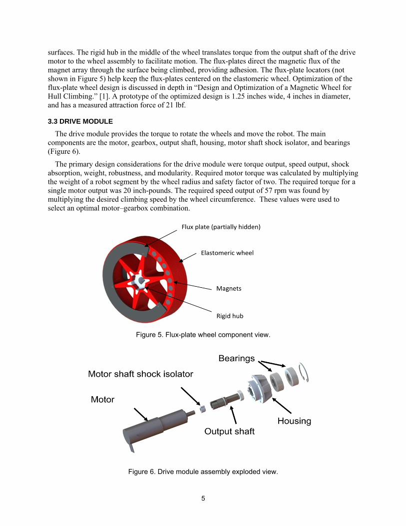
The flux-plate wheel components (Figure 5) consist of an elastomer wheel, two flux-plates, a flux-plate locator, a rigid hub, and an array of magnets oriented parallel to the central axis of the wheel. The magnets are positioned with all the north poles facing one side of the wheel, and the south poles facing the other. The elastomer wheel is made of 1-inch-thick neoprene. In addition to locating the other components of the wheel, it allows the entire assembly to flex during impacts with the ground. The outer surface of the wheel has a high coefficient of static friction, maximizing traction with hull
5
surfaces. The rigid hub in the middle of the wheel translates torque from the output shaft of the drive motor to the wheel assembly to facilitate motion. The flux-plates direct the magnetic flux of the magnet array through the surface being climbed, providing adhesion. The flux-plate locators (not shown in Figure 5) help keep the flux-plates centered on the elastomeric wheel. Optimization of the flux-plate wheel design is discussed in depth in “Design and Optimization of a Magnetic Wheel for Hull Climbing.” [1]. A prototype of the optimized design is 1.25 inches wide, 4 inches in diameter, and has a measured attraction force of 21 lbf.
3.3 DRIVE MODULE
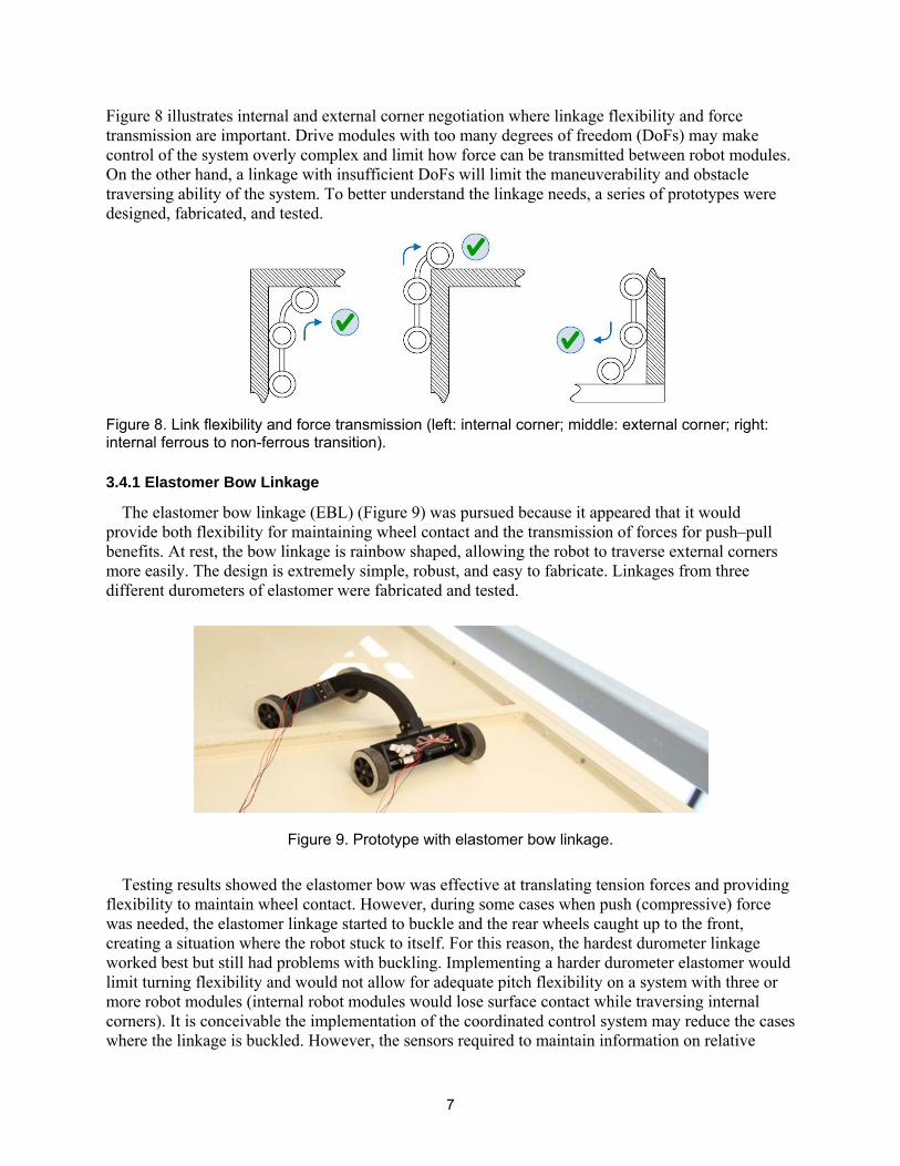
The drive module provides the torque to rotate the wheels and move the robot. The main components are the motor, gearbox, output shaft, housing, motor shaft shock isolator, and bearings (Figure 6).
The primary design considerations for the drive module were torque output, speed output, shock absorption, weight, robustness, and modularity. Required motor torque was calculated by multiplying the weight of a robot segment by the wheel radius and safety factor of two. The required torque for a single motor output was 20 inch-pounds. The required speed output of 57 rpm was found by multiplying the desired climbing speed by the wheel circumference. These values were used to select an optimal motor‒gearbox combination.
Figure 5. Flux-plate wheel component view.
Figure 6. Drive module assembly exploded view.

6
Table 1 Motor and gearbox requirements analysis.
Parameter Value
Robot segment weight (lbf) 10
Wheel diameter (inches) 4
Safety factor 2
Torque to climb (in‐lb) 40
Torque to climb/wheel (in‐lb) 20
Climbing speed (ft/sec) .5
Revolutions/minute (Rpm) 57
The development of the MMR was very dynamic, and experimentation and prototyping was used to try many different ideas. For this reason, modular designs were used for the drive modules, allowing them to be quickly moved from one robot chassis design to another. The entire drive module can be quickly detached from any chassis by removing four screws around the perimeter of the housing (Figure 7).
Figure 7. Drive module assembly.
Most unmanned ground vehicles are submitted to large shock loads as the robot traverses over rough ground. Robots that climb or are thrown tend to experience even larger shock loads in the inevitable case where they fall and hit the ground. Gearbox output shafts are often hardened and will easily break if a large radial load is experienced. For this reason, the drive module was designed to mitigate the effects of large shock loads where the robot falls onto the wheels. The output shaft is supported by two high-load bearings (Figure 6) directly coupled to the drive module housing. If the robot falls and impacts a wheel, the radial loads are distributed through the output shaft to the drive module housing and back to the robot chassis instead of to the gearbox output shaft. The motor shaft shock isolator allows relative motion between the output shaft and gearbox shaft during impacts thatcause the output shaft to deflect, while allowing torque to be transmitted from shaft to shaft for vehicle motion.
3.4 LINKAGE
The linkage, which makes the mechanical connection between the robot modules, must be flexible to allow the robot to turn and maintain wheel contact with the ferrous surface being climbed. It must also be able to transfer push (compressive) and pull (tension) forces between the robot modules so they can work in concert to overcome obstacles greater than the capability of any one robot module.
7
Figure 8 illustrates internal and external corner negotiation where linkage flexibility and force transmission are important. Drive modules with too many degrees of freedom (DoFs) may make control of the system overly complex and limit how force can be transmitted between robot modules. On the other hand, a linkage with insufficient DoFs will limit the maneuverability and obstacle traversing ability of the system. To better understand the linkage needs, a series of prototypes were designed, fabricated, and tested.
Figure 8. Link flexibility and force transmission (left: internal corner; middle: external corner; right: internal ferrous to non-ferrous transition).
3.4.1 Elastomer Bow Linkage
The elastomer bow linkage (EBL) (Figure 9) was pursued because it appeared that it would provide both flexibility for maintaining wheel contact and the transmission of forces for push‒pull benefits. At rest, the bow linkage is rainbow shaped, allowing the robot to traverse external corners more easily. The design is extremely simple, robust, and easy to fabricate. Linkages from three different durometers of elastomer were fabricated and tested.
Figure 9. Prototype with elastomer bow linkage.
Testing results showed the elastomer bow was effective at translating tension forces and providing flexibility to maintain wheel contact. However, during some cases when push (compressive) force was needed, the elastomer linkage started to buckle and the rear wheels caught up to the front, creating a situation where the robot stuck to itself. For this reason, the hardest durometer linkage worked best but still had problems with buckling. Implementing a harder durometer elastomer would limit turning flexibility and would not allow for adequate pitch flexibility on a system with three or more robot modules (internal robot modules would lose surface contact while traversing internal corners). It is conceivable the implementation of the coordinated control system may reduce the cases where the linkage is buckled. However, the sensors required to maintain information on relative

8
position of robot modules are anticipated to be much more complex than linkages with discrete DOFs. It is expected that some type of vision or beacon system would be required to implement a coordinated controller for a system with this type of linkage.
3.4.2 Rigid-Bow Linkage
A rigid-bow linkage was fabricated for evaluation on the two-segment prototype robot. The linkage looked exactly the same as the EBL except that it was fabricated from a piece of plywood that made the entire robot structure rigid. The robot could traverse obstacles similar to those of the EBL as long as it was perpendicular to the obstacle. The rigid linkage did not perform well if the obstacles were approached at an angle because not all four wheels could maintain contact with the surface being climbed. The rigid linkage also provided very poor turning capability.
3.4.3 Lockable Ball-Joint Linkage
A linkage design that includes a three-DOF ball joint that can lock the pitch-and-yaw DOFs when compressed was designed, prototyped, and tested (Figure 10). The idea behind this concept is that for compressive force to be translated from one robot module to the next, the ball joint must be locked in the pitch DOF or the linkage will simply start to fold on itself. The ball-joint design allowed the wheels to maintain surface contact with pitch, roll, and yaw DOFs. The design also allowed tension (pull) forces through the ball joint. Inside the ball joint, a spring pushes the ball into the normal operating position, but when a compressive force between the robot modules starts to compress the spring, the ball slides further into its receptacle and the pitch-and-yaw DOFs are constrained. As the compressive force diminishes the spring returns to its original position and the joint regains its full range of motion.
Figure 10. Lockable ball-joint linkage (unlocked).
The spring implemented on this design was too rigid and unable to be compressed by the robot modules. Additionally, the range of motion of the ball joint was not enough to allow the robot to traverse external corners. Conceivably, the lockable ball-joint design could be implemented on a bow-shaped linkage, allowing the traversal of external corners. A spring with a lower spring rate could also be integrated into the system to better evaluate the feasibility of this design.
3.4.4 Yaw Bow Linkages
For a robot with only two drive modules, a pitch DoF is not needed to maintain wheel contact when traversing an internal corner. For this reason, a single DoF bow linkage was developed. The first prototype simply included a hinge point in the middle of the bow linkage. The linkage proved effective for turning, but if the system was accidentally turned too much (which happened often with

9
the manually controlled prototype), wheels from the adjacent robot modules could get stuck together. To mitigate this failure mode, a second prototype was developed with a limited range of motion at the hinge point. Instead of using a traditional hinge, a leaf spring was designed as the pivot to try to bias the robot towards a position where the front and rear wheels were aligned. The design resembled a simplified saloon door concept. The wires connecting the front and rear robot module were run through the middle of the linkage and along the sides of the leaf spring. The pivot and range limiting portions of the design worked well, allowing effective turning without allowing wheel-to-wheel contact. The spring contribution of the design was ineffectual since the torque produced by the wheels could easily overpower the spring. For future designs, using a spring to provide a bias at a joint is ineffective for this application. The coordinated control system can implement the robot module relative position control more effectively and efficiently.
Figure 11 Yaw-bow linkage (spring hinge).
3.5 ELECTRONICS
The electronics used in the MSMR can be grouped in to four major categories: power, communication, sensing, and output. The power group consists of the wires, battery, and circuitry to manage and distribute power throughout the system. The processing group consists of the processor, radio, circuitry, and wires to distribute communications. The sensing group includes the wheel encoders, linkage encoders, camera, and future payloads that may be added to gather information. The output group consists of the motors and motor drivers. A high-level block diagram of the electronics is shown in Figure 12.
Figure 12. Electronics block diagram.

10
4. SOFTWARE
Software for the MSMR can be divided into robot module, operator control, and coordinated control. Robot module software runs on integrated circuits within the robot module, and is responsible for low-level functionality of the robot such as motor control and battery-level monitoring. The coordinated control software receives feedback from the motor encoders and relative positioning sensors and provides the commands to the motor controllers for optimal motion along the robot's path. Operator control software will run on a laptop and provides the command and control interface for directing the robot and receiving information back from the robot.
4.1 ROBOT MODULE
Most robot module software developed specifically for the MSMR runs under Linux on a Gumstix® Overo Fire COM within each robot module. WiFi provided by the Overo Fire COM is used for communication between robot modules and the operator control unit (OCU). Software on the MSMR executes low-level tasks and communications such as battery-level reporting, motor control, and sensor-data routing. Motor control software provides basic movement commands from the OCU via the Overo processor to the motor controllers.
4.2 OPERATOR CONTROL UNIT
The operator control unit will be a laptop or tablet with the Microsoft® Windows operating system and the multi-robot operator control unit (MOCU) application software (Figure 13). Used for controlling a wide variety of unmanned systems, MOCU was designed from the ground up to be modular and scalable so it could be used with both existing and future platforms. The modularity has been extended to the user interface as well, making it possible to create the full gamut of user interfaces, ranging from headless to tiled windows to completely immersive game-like displays. While the modules are used primarily for interfacing to different protocols, specialized hardware, video decoding and the like, most of the user interface is defined in XML configuration files, making it relatively easy to customize what the display looks like and how the user interacts with the system, whether this be via mouse, keyboard, touchscreen, joystick, or other input devices. Control of the MSMR through a MOCU will provide video feedback and joystick control for the prototype system. In the future, feedback from new sensors, battery life, robot pose, and other relevant information and control interfaces may be added.
Figure 13. Typical MOCU configuration for ground robot control.
11
4.3 COORDINATED CONTROL
The coordinated control software (CCS) will coordinate the motion of the drive modules to allow the MSMR to climb, turn, and scale obstacles more effectively. CCS will be developed in year two of the project. MATLAB® will be used for prototyping and then be implemented in C or Python. Each wheel on the MSMR is actuated individually, providing its own output speed. Control of each wheel of a four-wheel-drive robot by an operator is achievable but difficult. Development of a prototype MSMR with four wheels controlled through a standard radio controller (RC) clearly demonstrated the need for a coordinated controller. Controlling more than four wheels by an operator would be extremely difficult if not impossible. For this reason, coordinated control software will be pursued in year two of the MSMR project.
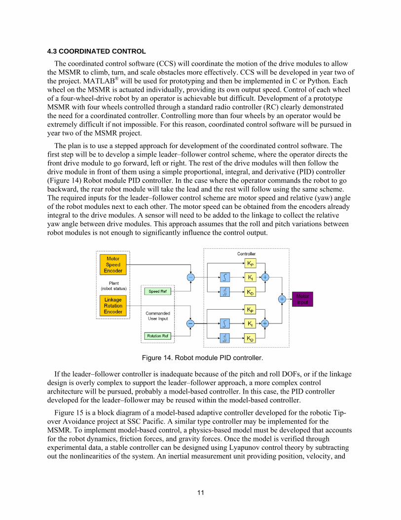
The plan is to use a stepped approach for development of the coordinated control software. The first step will be to develop a simple leader‒follower control scheme, where the operator directs the front drive module to go forward, left or right. The rest of the drive modules will then follow the drive module in front of them using a simple proportional, integral, and derivative (PID) controller (Figure 14) Robot module PID controller. In the case where the operator commands the robot to gobackward, the rear robot module will take the lead and the rest will follow using the same scheme.The required inputs for the leader‒follower control scheme are motor speed and relative (yaw) angleof the robot modules next to each other. The motor speed can be obtained from the encoders already integral to the drive modules. A sensor will need to be added to the linkage to collect the relative yaw angle between drive modules. This approach assumes that the roll and pitch variations betweenrobot modules is not enough to significantly influence the control output.
Figure 14. Robot module PID controller.
If the leader‒follower controller is inadequate because of the pitch and roll DOFs, or if the linkage design is overly complex to support the leader‒follower approach, a more complex control architecture will be pursued, probably a model-based controller. In this case, the PID controller developed for the leader‒follower may be reused within the model-based controller.
Figure 15 is a block diagram of a model-based adaptive controller developed for the robotic Tip-over Avoidance project at SSC Pacific. A similar type controller may be implemented for the MSMR. To implement model-based control, a physics-based model must be developed that accounts for the robot dynamics, friction forces, and gravity forces. Once the model is verified through experimental data, a stable controller can be designed using Lyapunov control theory by subtracting out the nonlinearities of the system. An inertial measurement unit providing position, velocity, and

12
acceleration feedback will be critical for implementing such a controller, in addition to relative position sensors and motor encoders.
Figure 15. Tip-over avoidance dynamic model adaptive controller.
5. SYSTEM PROTOTYPES
Two prototypes were developed in the first year of this project. The first, a two-segment robot with RC components, was developed to quickly test different variations of subsystem components such as the drive module, magnetic wheels, and linkage. The second, a three-segment system with integrated processors, will be used in year two to develop coordinated control software for the system.
5.1 RC PROTOTYPE
The RC prototype was tested with a variety of different linkage concepts. The yaw-bow linkage only provided a single DoF in the yaw axis, but proved the most effective of those tested with the RC controller. The system successfully climbed at 0.5 ft/sec and negotiated internal corners, external corners, and obstacles as big as 3 inches. It could also turn on vertical, horizontal, and inverted horizontal ferrous surfaces (Figure 16, Figure 17, Figure 18, Figure 19). The linkage did not provide a roll DoF, resulting in the loss of wheel contact if an obstacle or angular transition was not traversed orthogonally to vehicle motion. Often, when wheel contact was lost the robot would fall from the surface being climbed. It is expected that the addition of a roll DoF would improve the system’s mobility.
Figure 16. RC prototype climbs 1.5-inch obstacle.

13
Figure 17. RC prototype traverses internal corner.
Figure 18. RC prototype climbs exterior corner.
5.2 THREE-SEGMENT COMPUTER CONTROLLED PROTOTYPE
The three-segment computer controlled prototype is being fabricated at the time this report is being written, and an image of the CAD model is provided in Figure 20. It is expected that the three-segment prototype will be more mobile than the two-segment system, but will require implementa-tion of the coordinated control system.
Figure 19. RC prototype turning.

14
Figure 20. Rendering of three-segment MSMR.
6. CONCLUSION
The prototype systems developed in year one of the MSMR project demonstrated that a multi-segmented magnetic robot with relative DoFs between modules can effectively climb and negotiate ferrous surfaces with discontinuities, obstacles, internal corners, and external corners. Additional development and maturation of the mechanical, electrical, and software systems is required before the system is ready for testing in operational scenarios. The technology is promising for use in maritime interdiction operations and vessel hull and tank inspections, with the potential to increase safety, effectiveness, and efficiency of personnel involved in maritime operations.
7. REFERENCES
[1] M. Kerber, A. Burmeister, B. Dick, and A. Brune. 2013. “Design and Optimization of a Magnetic Wheel,” SPAWAR Systems Center Pacific (SSC Pacific) Technical Report 2025 (September), San Diego, CA.

5f. WORK UNIT NUMBER
REPORT DOCUMENTATION PAGEForm Approved
OMB No. 0704-01-0188
The public reporting burden for this collection of information is estimated to average 1 hour per response, including the time for reviewing instructions, searching existing data sources, gathering and maintaining the data needed, and completing and reviewing the collection of information. Send comments regarding this burden estimate or any other aspect of this collection of information, including suggestions for reducing the burden to Department of Defense, Washington Headquarters Services Directorate for Information Operations and Reports (0704-0188), 1215 Jefferson Davis Highway, Suite 1204, Arlington VA 22202-4302. Respondents should be aware that notwithstanding any other provision of law, no person shall be subject to any penalty for failing to comply with a collection of information if it does not display a currently valid OMB control number. PLEASE DO NOT RETURN YOUR FORM TO THE ABOVE ADDRESS.
1. REPORT DATE (DD-MM-YYYY) 2. REPORT TYPE 3. DATES COVERED (From - To)
4. TITLE AND SUBTITLE 5a. CONTRACT NUMBER
5b. GRANT NUMBER
5c. PROGRAM ELEMENT NUMBER
5d. PROJECT NUMBER
5e. TASK NUMBER
6. AUTHORS
7. PERFORMING ORGANIZATION NAME(S) AND ADDRESS(ES) 8. PERFORMING ORGANIZATION REPORT NUMBER
10. SPONSOR/MONITOR’S ACRONYM(S)
11. SPONSOR/MONITOR’S REPORT NUMBER(S)
9. SPONSORING/MONITORING AGENCY NAME(S) AND ADDRESS(ES)
12. DISTRIBUTION/AVAILABILITY STATEMENT
13. SUPPLEMENTARY NOTES
14. ABSTRACT
15. SUBJECT TERMS
16. SECURITY CLASSIFICATION OF: a. REPORT b. ABSTRACT c. THIS PAGE
17. LIMITATION OF ABSTRACT
18. NUMBER OF PAGES
19a. NAME OF RESPONSIBLE PERSON
19B. TELEPHONE NUMBER (Include area code)
Standard Form 298 (Rev. 8/98)Prescribed by ANSI Std. Z39.18
September 2013 Applied Research
Design of a Multi-Segmented Robot for Hull Climbing A NISE funded Applied Research Project
Aaron Burmeister Narek Pezeshkian Kurt Talke Abraham Hart Gary Gilbreath
SSC Pacific, 53560 Hull Street, San Diego, CA 92152–5001 TR 2028
Naval Innovative Science and Engineering Program SSC Pacific, 53560 Hull Street, San Diego, CA 92152–5001
NISE
Approved for public release.
This is work of the United States Government and therefore is not copyrighted. This work may be copied and disseminated without restriction.
A magnetic wheel was designed, optimized, prototyped, and tested for use on the Multi-segmented Magnetic Robot (MSM) project. The wheel provides magnetic attraction force to ferrous surfaces, allowing the robot to climb ship hulls. This capability could be used to meet the intelligence, surveillance, and reconnaissance needs of Navy visit, board, search, and seizure (VBSS), Navy SEALs, and Marine Force Reconnaissance teams.
Two different magnetic wheel designs, the flux-plate wheel and conformal wheel, were evaluated to select the most promising design for use on the MSM robot. The flux-plate wheel was the clear winner, providing over four times as much attraction force as a similarly sized conformal wheel.
An optimization study of the flux-plate wheel showed that increasing the thickness of the flux-plate and the number of magnets in the wheel provided a greater increase in the attraction force than the varying of other design parameters. An optimized wheel was designed using measured results, simulated results, manufacturing, and design considerations. The optimized wheel was 1-inch thick, had a 4-inch outer diameter (OD), 36 0.25-inch OD by 1-inch long N52 Neodymium magnets, and 0.125-inch thick flux-plates. The wheel weighed 1.22 pounds and provided an attractive force of 21 lbf. naval visit, board, search, and seizure flux-plate wheel multi-segmented magnetic robot hull cleaning ship hull climbing conformal wheel
Aaron Burmeister
U U U U 19 (619) 553-5576

INITIAL DISTRIBUTION
84300 Library (2) 85300 Archive/Stock (1) 71720 Aaron Burmeister (1)
Defense Technical Information Center Fort Belvoir, VA 22060–6218 (1)

Approved for public release.
SSC Pacific San Diego, CA 92152-5001