Embed Size (px)
Citation preview
Design of a new waveguide slotted antenna array
Teng Li, and Wenbin Dou
State Key Laboratory of Millimeter Waves
Southeast University
Nanjing 210096, China
[email protected], [email protected]
Abstract—In this paper, a new waveguide slotted antenna array, in which T-shaped cross section
waveguide is used as the radiating waveguide, is proposed and simulated. The T shaped radiating
waveguide can reduce the waveguide profile height. The radiating slots are etched and inclined alternately
on the top [1, 2, 3]. The metal fences are introduced between slots to repress the sidelobe level of E-plane [4].
A bend structure is invented to feed the T-shaped radiating waveguide [3, 5]. A 2 6 antenna array working
at Ka-band is designed and the obtained simulated results demonstrate this novel structure.
Keywords—antenna array; slot; T-shape; waveguide
References
[1] X.W. Zhao, Y. Zhang, T.K. Sarkar, S.W. Ting, and C.H. liang, “Analysis of a traveling-wave waveguide array with narrow-wall slots using higher order basis functions in method of moments,” IEEE Antennas Wireless Propag. Lett., vol. 8, pp. 1390-1393, 2009.
[2] S. Silver, “Linear array antennas and feeds” in Microwave Antenna Theory and Design, 1st ed., New York: McGraw-Hill, 1949, pp. 291-303.
[3] T. Li, H.F. Meng, and W.B. Dou, “Design and implementation of dual-frequency dual-polarization slotted waveguide antenna array for Ka-band aplication,” IEEE Antennas Wireless Propag. Lett., vol. 13, 2014, pp. 1317-1320.
[4] T. Li, H.F. Meng, and W.B. Dou, “The analysis of broadband slotted antenna array,” 2nd Asia-Pacific Conference on Antennas and Propagtion, August 5-7, 2013, pp. 15-16.
[5] Y.F. Fang and X.Q. Yan, “A rectangle waveguide four-way divider for wideband and miniaturization application,” IEEE 5th Internation Sym. MAPE, 2013, pp.315-318.
Forum for Electromagnetic Research Methods and Application Technologies (FERMAT)
*This use of this work is restricted solely for academic purposes. The author of this work owns the copyright and no reproduction in any form is permitted without written permission by the author.*

SOUTHEAST
UNIVERSITY
毫米波国家重点实验室State Key Lab. Of Millimeter Waves
中国·南京Nanjing·China
Design of a New Waveguide Slotted Antenna Array
Teng�Li�and�Wenbin Dou2015-03
State Key Laboratory of Millimeter Waves, Southeast University
Contents
Introduction1
T-shaped Waveguide2
1×6 Linear Array3
Conclusions6
Metal Fences4
2×6 Antenna Array5
Introduction
Southeast University State Key Lab. Of Millimeter Waves
Slotted waveguide antenna array is a good candidate for using in radar systems and communication systems due to its low power loss, low profile, low cross-polarization levels, high efficiency, high power capacity, and accurate control of amplitude and phase distributions. The radiating slots are commonly etched on the wide-wall or narrow-wall of waveguide. The slots etched on the narrow-wall must cut into the broadside for resonance, furthermore, the height of profile is increased compared with the other one. In this paper, a T-shaped waveguide is proposed and a 2 6 antenna array with metal fences working at 35 GHz is designed based on this new waveguide. The radiating slots etched on the top of waveguide without cutting into the broadside and the height of profile is decreased.
T-shaped Waveguide
Southeast University State Key Lab. Of Millimeter Waves
Waveguide Type Dominant Mode Higher Modes Surface Current Distribution
Actually, the T-shaped waveguide can be seen as a half of double ridge waveguide which owns wider bandwidth. For the same guide wavelength, the new waveguide has a lower profile.
λg=16.00mm
h
h1+h2=1.5mm+2.47mm=3.97mmh=5.07mm>
For the dominant mode, the port field of T-shaped is in the horizontal direction as the rectangular one. For the higher modes, the electromagnetic wave can not propagate at the center frequency. Therefore, only the dominant mode is excited. Due to the surface current distribution of T-shaped waveguide is similar to the rectangular waveguide, the inclined slot can be used to cut the electric current and radiate the power. The top wall of waveguide is broadened, therefore, the slot can be resonant without cutting into the other waveguide wall.
1×6 Linear Array
Southeast University State Key Lab. Of Millimeter Waves
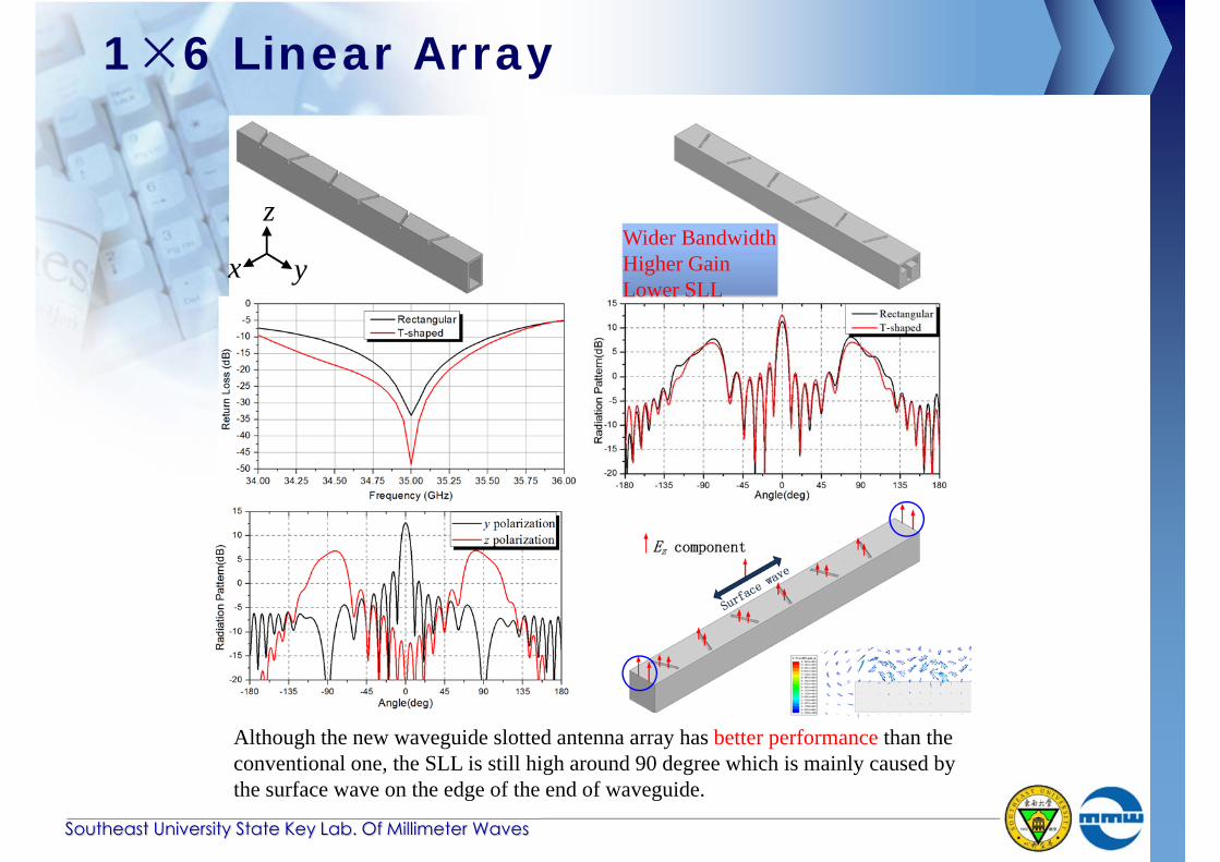
Although the new waveguide slotted antenna array has better performance than the conventional one, the SLL is still high around 90 degree which is mainly caused by the surface wave on the edge of the end of waveguide.
x y
zWider BandwidthHigher GainLower SLL
Metal Fences
Southeast University State Key Lab. Of Millimeter Waves
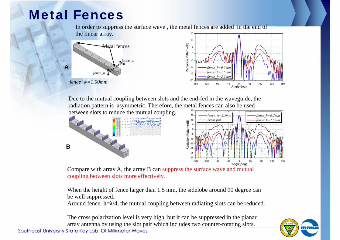
In order to suppress the surface wave , the metal fences are added in the end of the linear array.
Metal fences
fence_h
fence_w
Due to the mutual coupling between slots and the end-fed in the waveguide, the radiation pattern is asymmetric. Therefore, the metal fences can also be used between slots to reduce the mutual coupling.
fence_w=1.00mm
Compare with array A, the array B can suppress the surface wave and mutual coupling between slots more effectively.
When the height of fence larger than 1.5 mm, the sidelobe around 90 degree can be well suppressed. Around fence_h=λ/4, the mutual coupling between radiating slots can be reduced.
The cross polarization level is very high, but it can be suppressed in the planar array antenna by using the slot pair which includes two counter-rotating slots.
A
B
2×6 Antenna Array
Southeast University State Key Lab. Of Millimeter Waves
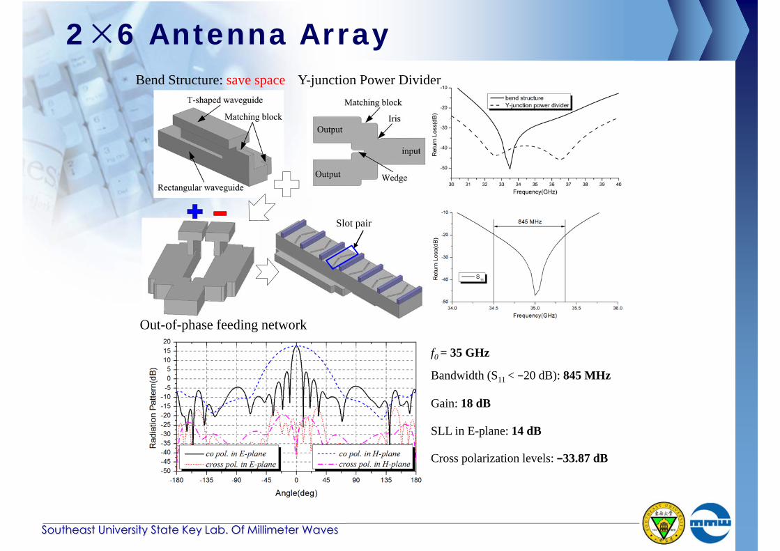
f0 = 35 GHz
Bandwidth (S11 < −20 dB): 845 MHz
Gain: 18 dB
SLL in E-plane: 14 dB
Cross polarization levels: −33.87 dB
Bend Structure: save space Y-junction Power Divider
Out-of-phase feeding network
Slot pair
Conclusions
Southeast University State Key Lab. Of Millimeter Waves
The proposed T-shaped waveguide is analyzed and a new slotted antenna working at 35 GHz is designed based on this novel structure. The simulated results indicate the effectiveness of the proposed structure including the T-shaped structure and metal fence. Due to no slots cutting into the broadside of waveguide, this novel antenna can easily interlaced with a ridged waveguide slotted antenna working at the other frequency band to realize dual frequency and dual polarization performance. In summary, the proposed is an attractive candidate for radar and communication systems.


![A 32-GHz Microstrip Array Antenna for Microspacecraft ... · A 32-GHz Microstrip Array Antenna for Microspacecraft Application ... is the planar slotted waveguide array [2], ... posed](https://img.pdfslide.net/doc/110x75/5b344a987f8b9aa0238dc5e2/a-32-ghz-microstrip-array-antenna-for-microspacecraft-a-32-ghz-microstrip.jpg)


![High Gain Slotted Waveguide Antenna Based on Beam Focusing ...jpier.org/PIERC/pierc79/10.17020705.pdf · 116 Abdelrehim and Ghafouri-Shiraz can be designed [12,13]. It is well know](https://img.pdfslide.net/doc/110x75/5e1289a00e06fc52b6565fe8/high-gain-slotted-waveguide-antenna-based-on-beam-focusing-jpierorgpiercpierc7910.jpg)


![A 140 GHz High Efficiency Slotted Waveguide Antenna using ... · integrated waveguide (SIW) slot antenna array [6]-[8], and the 400 GHz folded reflectarray [9]. Among them, the slotted](https://img.pdfslide.net/doc/110x75/5f01d7e07e708231d4014f46/a-140-ghz-high-efficiency-slotted-waveguide-antenna-using-integrated-waveguide.jpg)


![A linearly slotted waveguide antenna and comparison of it with a … · Although slotted waveguide antennas are one of the oldest antenna types [1], they are still applied in telecommu-nication](https://img.pdfslide.net/doc/110x75/6119a3ff77ae5a635618e78d/a-linearly-slotted-waveguide-antenna-and-comparison-of-it-with-a-although-slotted.jpg)