Embed Size (px)
Citation preview

Design of a Radioactive Source Sampler Based on CPAC
Bin Yang1, Zhenyu Wang2
1 Department of Automation Engineering, The Engineering and Technical College of Chen Du University of Technology, Leshan, Sichuan Province, 614007, China
2 Department of Automation Engineering, The Engineering and Technical College of Chen Du University of Technology,
Leshan, Sichuan Province, 614007, China
Abstract
This paper puts forward a design project of sampler for solving the difficult problem of radioactive source sampled by manual work because of radioactive source’s radioactivity. The project includes mechanical body’s design, controller’s design, and controller’s realization. According to mechanical body’s motion characteristics, advances an iterative learning algorithm of exponent variable-gain to design controller for the radioactive source sampler whose manipulator arm can follow the given tracks. The design can get satisfying track following control effect by computer simulation, and can content control demands of sampling process. On the realization of controller, applies Computer Programmable Automation Controller (CPAC) made in Googol Technology to sampler and gives its hardware’s realization method. Now the prototype tested has already substituted for tester to finish automatic sampling process in accordance with sampling program set in advance. Keywords: CPAC, motion controller, iterative learning, radioactive source sampler.
1. Introduction
The Southwestern Institute of Physics is the biggest controlled nuclear fusion experimental base in Asia. Its main research directions are magnetic confinement of controlled nuclear fusion. During the controlled nuclear fusion experiments, cannot be without use of radioactive elements (Cobalt-60, Cesium-137, and Iridium-192 etc). The sources are stored in the radioactive source library in Le Shan base. When need the radioactive sources, they are sampled by manual work from the underground to the workbench. It is dangerous that the sampling tester is placed in the radiation environment. In order to solve the problem, an automatic sampler is designed to substitute for tester. With the development of motion control technology, the universal motion controllers are widely and successfully used in robots, CNC machine tools, assembly lines, laser processing, and PCB drilling and milling equipments etc. The technology also provides reliable basis for solving automatic sampling problem. In the design, applies the CPAC that is an universal motion controller made in Googol Technology to the radioactive
source sampler for realizing to automatically take radioactive sources.
2. Working Principle of Mechanical Body
There are nine sources stored in the radioactive source library. They are arrayed in three lines and three rows. To realize automatic sampling, a mechanical sampler designed must have two active joints at least, and can freely do rotary motion. Two active joints and its rotary motion can easily adjust gripping device’s position according to the position of source sampled. So a sampler of radioactive source can be design as follows.
1—turbine reducer, 2—drive motor, 3—chassis,
4—rotary system, 5—auxiliary hoist system, 6—operation panel, 7—hoist motor, 8—humeral motor, 9—humeral arm,
10—joint motor, 11—gripping arm, 12—gripping device
Fig.1 Mechanical structure of sampler.
The sampler of radioactive source is made of turbine reducer, drive motor, chassis, rotary system, auxiliary hoist system, operation panel, humeral arm, gripping arm, and
IJCSI International Journal of Computer Science Issues, Vol. 10, Issue 2, No 2, March 2013 ISSN (Print): 1694-0814 | ISSN (Online): 1694-0784 www.IJCSI.org 211
Copyright (c) 2013 International Journal of Computer Science Issues. All Rights Reserved.

gripping device etc. The sampler of radioactive source’s working principle is as follows. Before sampling, a radioactive source gripped is placed in the lifting container, which is under the floor at 0.5 meters deep. When need sample, tester presses the buttons of number one to number nine on the operation panel or on the control desk in the control room outside the source library. Then the sampler computes each joint changed the angles accurately according to the position of the radioactive source gripped, and selects corresponding control program of the position. The gripping device will precisely move into the position of the radioactive source gripped and open its jaws. When a sensor detects a right depth’s signal, the hoist system stops dropping and its jaws begin to close up. At last, adjusts the two arm joints’ angle or auxiliary hoist system for slowly hoisting gripping device and accurately placing the sample on the workbench. The whole course entirely realizes automatic control.
3. Mechanical Structure
3.1 Auxiliary Hoist system
The motor drives a guide screw to whirl, the guide screw’s rotation will convert into linear motion of hoist and drop of the gripping device.
1—below the bottom plane, 2—lifting slide carriage,
3—guide sleeve, 4—guide post, 5—above the bottom plane, 6—guide screw, 7—nut, 8—bearing seat
Fig.2 Auxiliary hoist system.
The three guide posts are fixed reliably by the two bottom planes. And the guide screw’s radial and axial movements can be located by the bearing seat, the pillow block
bearings and the thrust bearing. The guide screw whirls at given speed. At the same time, the lifting slide carriage whose motion stroke is 400 millimeters moves along the guide post.
3.2 Two-joint Mechanical Arm
Two active joints’ mechanical arm can be adjusted to suitable angles by two AC servo motors. Two-joint mechanical arm’s motion trajectory is determined by the control program. Nine radioactive sources have nine independent control programs because of their different position. Mechanical arm’s controller design will be determined for its trajectory tracking in the back of the article.
3.3 Rotary System
As in Figure 3, rotary system consists of shaft end retaining ring, rotary disk, joint flange, bearing cover, bearing seat, bearing cover, and rotary axis.
1—shaft end retaining ring, 2—rotary disk, 3—joint flange, 4—bearing
on the cover, 5—bearing seat, 6—bearing under the cover, 7—rotary axis
Fig.3 Rotary system.
The bearing seat supports two tapered roller bearings. The rotary axis whirls in the bearing, which is fixed in the bearing seat, and is fixed with the shaft end retaining ring and the joint flange through a flat key. The joint flange is fixed with the rotary disk by screws. The motor drives the rotary axis to whirl and transmits torque to the rotary disk, which drives the whole rotary hoist system and gripping system whirling.
3.4 Gripping System
Gripping system mainly includes a permanent magnet low speed synchronous motor, fixed plate, screw, slider, positioning axis, T-frame, link, and gripper. Figure 4 shows the gripping system’s working principle. The permanent magnet low speed synchronous motor drives the screw to whirl. Then the slider can slide up and down, and slider can drive T-frame. The gripper turns around the positioning axis through the lever’s effect. The
IJCSI International Journal of Computer Science Issues, Vol. 10, Issue 2, No 2, March 2013 ISSN (Print): 1694-0814 | ISSN (Online): 1694-0784 www.IJCSI.org 212
Copyright (c) 2013 International Journal of Computer Science Issues. All Rights Reserved.

gripper’s rotary motion is limited by travel switch within the 0~15°range.
1—permanent magnet low speed synchronous motor,2—fixed plate,3—screw, 4—slider,5—positioning axis, 6—T-frame, 7—lever, 8—gripper
Fig.4 Gripping system.
4. Mathematical Model
In order to realize automatic control of the sampler, a controller must be designed for the two-joint mechanical arm’s trajectory tracking. However getting mathematical model of the system is only the first step. The radioactive resource sampler shown in Figure 1 can be simplified to the model as follows.
1q
2q
Fig.5 The model simplified.
Assume that point A is the system’s the origin of coordinates, point D is the centroid of lever 1, and point E is the centroid of lever 2. The centroid D’s coordinate is the ( 11, yx ), the active joint B’s coordinate is the
( 11, ymxm ), the centroid E’s coordinate is the ( 22, yx ), and gripping device C’s coordinate is the ( 22 , ymxm ). In Figure 5, there are some main physical variables shown in Table 1.
Table 1: Symbol, Meanings and Units for Physical Variables Symbol Meaning Unit
1l length of the lever 1 meter 2l length of the lever 2 meter
1m mass of the lever 1 kilogram 2m mass of the lever 2 kilogram 3m mass of the active join B kilogram 4m mass of the gripping device kilogram
1q angle between the lever 1 and the x-axis radian 2q angle between the lever 2 and the lever 1’
s extension line radian
According to the Figure 5, the system’s total kinetic energy T is that the lever 1’s rotational kinetic energy 1T around the origin A couples with the lever 2’s total kinetic energy
2T including rotational kinetic energy around the active join B and it’s parallel moving kinetic energy, and couples with the active joint B’s rotational kinetic energy 1mT and gripping device’s moving kinetic energy 2mT . Considering above mentioned the motion system’s kinetic energy T we have:
221
222
22
222
21
2112121
)(61)(
21
61
····
·
++++
=+++=
qqlmyxm
qlmTmTmTTT
)(21
21 2
2224
21
213
···
+++ ymxmmqlm (1)
The system’s total potential energy can be expressed as follows:
24132211 gymmgymmgymgymV +++= (2) In this paper, gets a mathematical model of the mechanical arm via Lagrange Equation. According to Lagrange Function L=T-V, equation (1) and equation (2) is substituted into the following Lagrange Equations.
ïï
î
ïï
í
ì
=¶¶
-
=¶¶
-
·
·
22
2
11
1
)(
)(
t
t
qL
q
Ldtd
qL
q
Ldtd
(3)
Where 1t and 2t are generalized force. Thus, can get relational expressions (4) and (5) as follows:
22142
22221212
143
212
2422142
222212
127
21(])
31(2
127[
CllmlmCllmqlmm
mmlmCllmlmCllm
+++++
+++++
··
+++++
++-+
··
·····
1212112111222214
22212122141221222
24
21
21()
212()
CglmCglmCglmqqSllm
qSllmqSllmqSllmqlm
111141224113 ) dCglmCglmCglm tt -=++ (4)
++++
+++
···
··
1221222
242
22
12
2422142
222212
21()
127(
)127
21(
qSllmqlmlm
qlmCllmlmCllm
2212241222112214 )21() dCglmCglmqqSllm tt -=++
·· (5)
In expression (4) and expression (5), 1C is )( 1qCos ,
2C is )( 2qCos ,
12C is )( 21 qqCos + ,2S is )( 2qSin , generalized
IJCSI International Journal of Computer Science Issues, Vol. 10, Issue 2, No 2, March 2013 ISSN (Print): 1694-0814 | ISSN (Online): 1694-0784 www.IJCSI.org 213
Copyright (c) 2013 International Journal of Computer Science Issues. All Rights Reserved.
force 1t and
2t are the driving torque of the first and second joint, and
1dt and 2dt are outside the disturbance.
Equation (4) and equation (5) are seeking the mathematical model of the mechanical arm. This is a typical nonlinear system, whose control goal is that the end of the mechanical arm’s position and speed, etc. can track a given ideal trajectory via given the driving torque of each joint. The following will detail a controller design method for trajectory tracking.
5. The Exponent Variable Gain Iterative Learning
Because iterative learning control algorithm is simple, and is able to achieve high precision trajectory tracking control in the given time, it is widely used in nonlinear system’s control objects. Its basic control principle is: to set the desired output and the each running initial state, repeats learning control algorithm according to a certain calculation within a given time so that makes the control input )()( tutu dk ® , and makes the system’s output
)()( tyty dk ® . According to the control object’s nonlinear feature, the paper uses closed loop variable gain exponential D-type iterative learning control algorithm to realize the mechanical arm’s trajectory tracking control. Its basic control law is as follows.
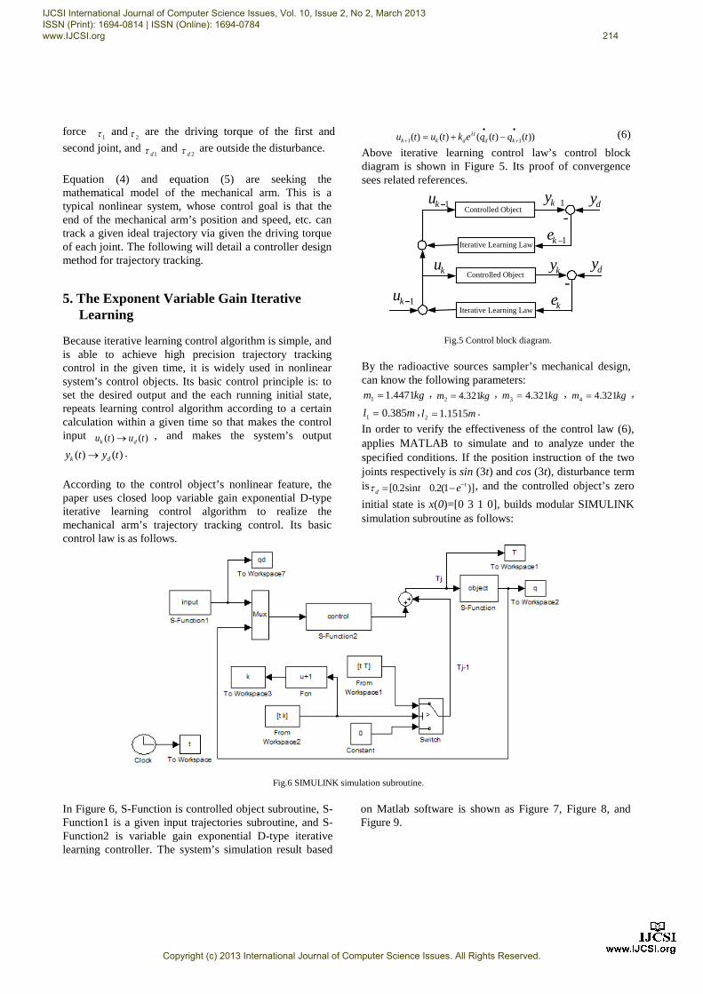
))()(()()( 11 tqtqektutu kdt
dkk
·
+
·
+ -+= l (6) Above iterative learning control law’s control block diagram is shown in Figure 5. Its proof of convergence sees related references.
1ku 1ky dy-1ke
Controlled Object
ku ky dy-
ke1ku
Controlled Object
Iterative Learning Law
Iterative Learning Law
Fig.5 Control block diagram.
By the radioactive sources sampler’s mechanical design, can know the following parameters:
kgm 4471.11 = , kgm 321.42 = , kgm 321.43 = , kgm 321.44 = ,
ml 385.01 = , ml 1515.12 = . In order to verify the effectiveness of the control law (6), applies MATLAB to simulate and to analyze under the specified conditions. If the position instruction of the two joints respectively is sin (3t) and cos (3t), disturbance term is )]1(2.0sin2.0[ t
d et --=t , and the controlled object’s zero initial state is x(0)=[0 3 1 0], builds modular SIMULINK simulation subroutine as follows:
Fig.6 SIMULINK simulation subroutine.
In Figure 6, S-Function is controlled object subroutine, S-Function1 is a given input trajectories subroutine, and S-Function2 is variable gain exponential D-type iterative learning controller. The system’s simulation result based
on Matlab software is shown as Figure 7, Figure 8, and Figure 9.
IJCSI International Journal of Computer Science Issues, Vol. 10, Issue 2, No 2, March 2013 ISSN (Print): 1694-0814 | ISSN (Online): 1694-0784 www.IJCSI.org 214
Copyright (c) 2013 International Journal of Computer Science Issues. All Rights Reserved.

Fig.7 20 iterations learning tracking process.
Fig.8 The twentieth iterative learning.
Fig.9 Error norm convergence process.
As can be seen from the above simulation results, iterative learning controller is able to effectively track a given signal and error norm can converge after 10 iterations learning. This also shows that the variable gain exponential D-type iterative learning control algorithm has
a good control effect for the two-joint mechanical arm of the radioactive source sampler, so can consider the problem of realization of iterative learning controller.
6. Iterative Learning Controller’s Realization
Following an iterations learning controller will be realized by CPAC made in Googol Technology to carry out real-time control and management for the sampler, so that the mechanical arm’s movement can be in accordance with the anticipated trajectory and a predetermined parameter of the motion. Full name of CPAC is the computer programmable automation controller, which is the controller of an embedded industrial PC, PLC, and motion controller with stability, anti-interference ability, high reliability, and high value for money. The CPAC will become the core of the control of radioactive sources sampler, and the variable gain exponential D-type iterative learning control algorithm is implemented by CPAC via OtoStudio soft. Then control instructions will be issued by CPAC, and servo motors will be driven by servo drives in accordance with the given trajectory movement. Figure 10 is the control structure principle realization diagram for the sampler’s joints control.
Fig.10 Control structure principle realization diagram
According to CPAC and terminal board interface definition, a dedicated 50PIN cable connects between CPAC controller’s AXIS1-4 interface and terminal board CN17 interface for reading switches’ signal on the terminal board interface and axes’ position signal. And calculates directly to obtain the k+1 time’s error signal of the position, and sends the k+1 time’s iterative learning control instruction to the two servo drives to drive the two servo motors for coordinated movement in accordance with the given track. On the terminal board, CN9 and CN11 are some general purpose digital I/O interfaces, which can be designed for two sets of buttons. One set is installed in the radioactive source sampler’s operational panel; the other set is installed in the control room outside the source library. This design helps to realize the control in two different places. The test members are able to complete sampling operation in the control room without entering the source library. In this paper, the iterative
IJCSI International Journal of Computer Science Issues, Vol. 10, Issue 2, No 2, March 2013 ISSN (Print): 1694-0814 | ISSN (Online): 1694-0784 www.IJCSI.org 215
Copyright (c) 2013 International Journal of Computer Science Issues. All Rights Reserved.
learning controller can be realized by CPAC, but the specific circuits will be omitted. In fact, prototype testing has begun, and achieved good effect.
7. Conclusions
This paper focuses on a radioactive source sampler’s mechanical structure design and its controller design for solving the problem of automation sample. The production of mechanical body proves the effectiveness of the design of the mechanical structure. On controller design, the closed-loop variable gain exponential D-type iterative learning control strategy is successfully used, and fully takes into account the disturbance of the system. The simulation results show that the iterative learning controller has good control effect for the two-joint mechanical arm. On this basis, puts forward to use CPAC for the system’s control core. Now the prototype has been made and put into trial operation, whose results is satisfactory and fully realizes automatic sample without human intervention. Prototype testing proves that the mechanical structure design and control scheme is reasonable and feasible, and easy implement.
Acknowledgments
The help of Li Song, Senior Engineer of the Southwestern Institute of Physics in the preparation of this paper is gratefully acknowledged. We also acknowledge the financial support of youth research and development fund by the engineering and technical college of Chen Du University of Technology. References [1] Dong Jiaqi, “Tokamak high confinement operation mode and
controlled nuclear fusion through magnetic confinement”, Physics, Vol. 39, No. 6, 2010, pp. 400-405.
[2] Han B, Lin X G, “Adapt steady state Kalman gain using the normalized autocorrelation of innovations”, IEEE Signal Processing Letters, Vol. 12, No. 11, 2005, pp.780-783.
[3] Jin Ho SUH, Jin Woo Lee, Young Jin Lee, “Antisway control of an ATC using NN predictive PID control”, Proceedings of the 30th annual conference of the IEEE industrial electronics society, Busan, Korea, 2004, pp. 2998 -3003.
[4] Li Maoqing, “Controller design for 2-DOF under actuated mechanical systems based on controlled Lagrangians and application to the Acrobot control”, Frontiers of Electrical and Electronic Engineering in China, Vol. 4, No.4, 2009, pp. 417-439.
[5] Li Yizhong, Xia Tian, “The AGV controller system design based on CPAC”, Mechanical and Electrical Engineering, Vol. 40, No. 2, 2011, pp. 37-38.
[6] Park K.H, Bien Z. Hwang D.H, “A Study on the Robustness of a PID-type Iterative Learning Controller against Initial State Error”, International Journal of Systems Science, Vol. 30, No. 1, 1999, pp. 49-59.
[7] Piao Fengxian, Zhang Qinling, “Analysis of convergence rate for iterative learning control”, Journal of Northeastern University(Natural Science) , Vol. 27, No. 8, 2006, pp. 835-838.
[8] Xu Yuxing, “Some suggestions on the current application and management of radioactive sources”, Sci-Tech Information Development and Economy, Vol. 17, No. 1, 2007, pp. 296-297.
[9] Zhang Peng, Zhao Hui, “Design of force/ position hybrid control based on googoltech industrial robot”, Machinery Design and Manufacture, No. 4, 2011, pp.153-155.
[10]EI Sayed M. Saad, Medhat H. Awadalla, Hosam Eldin I. Ali, Rasha F. A. Mostafa, “Interactive learning for humanoid robot”, International Journal of Computer Science Issues, Vol. 9, No. 4, 2012, pp. 331-336.
First Author received the Master degree at Wuhan University of Science and technology in 2007. Currently, he is employed at the engineering and technical college of Chen Du University of Technology and engaged in teaching and research work of the automatic control. His interests are in advanced control theory and applications and mechanical and electrical integration technology. Second Author received the Master degree at Jilin University in 2007. Currently, he is employed at the engineering and technical college of Chen Du University of Technology and engaged in teaching and research work of mechanical engineering.
IJCSI International Journal of Computer Science Issues, Vol. 10, Issue 2, No 2, March 2013 ISSN (Print): 1694-0814 | ISSN (Online): 1694-0784 www.IJCSI.org 216
Copyright (c) 2013 International Journal of Computer Science Issues. All Rights Reserved.