Embed Size (px)
Citation preview
Design of a Retrofittable Alternative to the Double HullOil Tanker
by
Randy Thomae
Submitted to the Department of Mechanical Engineering
in partial fulfillment of the requirements for the degree of
Masters of Science
at the
MASSACHUSETTS INSTITUTE OF TECHNOLOGY
February 1, 1995
© 1995 Randy Thomae. All rights reserved.The author hereby grants to MIT permission to reproduce and to distribute publicly paper
and electronic copies of this thesis docvment-ia-Whole or in part.
A uthor............................................... ........ .....................
Department of Mechanical Engineering
February, 1995
C ertified by ........................ .............. ... ).. .... ..................... ........
Professor Carl Peterson
Department of Mechanical Engineering
Thesis Supervisor
A ccepted by .............................................................. ............................
Ain A. Sonin
Head of Graduate Committee
Department of Mechanical Engineering
Eng*MASSACHUSET'S INSTITUTE
OF TE(CHNOLOGY
'"APR 06 1995U.gBARIE$

ABSTRACT
Design of a Retrofittable Alternative to the Double Hull
Oil Tanker
by
Randy Thomae
Submitted to the Department of Mechanical Engineering on January 5, 1995,
in partial fulfillment of the requirements for the degree of
Masters of Science
Abstract
This thesis describes the design and motivation for a retrofittable alternative to the double
hull oil tanker. Public outrage following the Exxon Valdez oil spill motivated
international and domestic legislation requiring double hull oil tankers. The double hull
design requires major structural modification to single hull tankers meaning that the
double hull is expensive, it can't be retrofitted on existing vessels, and it may introduce
technical problems. The Oil-Safe design described herein is a retrofittable composite
liner system requiring no major structural changes to existing tankers. The design
consists of a flexible barrier composed of an impermeable liner to contain the cargo and a
reinforcement curtain to resist local penetrations, and a foam foundation to space the
curtain and liner away from the tanker hull. By utilizing a flexible inner liner that moves
out of the way of impinging objects, the design is incapable of sustaining any load. The
Oil-Safe system is believed to be easily retrofittable, inexpensive, and more effective than
the single or double hull designs.
Thesis Supervisor: Carl Peterson
Title: Associate Professor of Mechanical Engineering
Oil-Safe. MIT
OiI-Safe. MIT

TABLE OF CONTENTS
TABLE OF CONTENTS
1. OVERVIEW 7
1.1 The Oil Protection Act of 1990 (OPA 90) 9
1.2 The Double Hull Oil Tanker 10
1.3 Alternative Designs 11
1.3.1 Protectively Located non-cargo tanks (PL/Spaces)/Segregated Ballast Tanks(SBT) 11
1.3.2 Mid-Deck Tanker 11
1.3.3 Emergency Rescue System(ERS) 12
1.3.4 Emergency Rapid Transfer System(ERTS) 12
1.3.5 Underpressure System(UPS) 12
1.3.6 Hydrostatic Balanced Loading(HBL) 12
1.4 The Oil-Safe Alternative Design 13
1.5 Documentation 14
2. THE OIL TRANSPORTATION INDUSTRY 15
2.1 Small vs. Large Shippers 15
2.2 US Oil Supply 16
2.3 The World Tanker Fleet 17
2.4 Charter Rates 18
2.5 Summary of the Oil Transportation Industry 19
3. OIL SPILLS 20
3.1 The causes of Oil Spills 22
Oil-Safe. 3 of 59
TABLE OF CONTENTS
3.2 Costs of Oil Spills 24
33 Summary: 25
4. OIL SPILL REGULATION 26
4.1 Congress - Oil Pollution Act of 1990(OPA 90) 26
4.1.1 The Double Hull Requirement 26
4.1.2 Alternative Measures 28
4.1.3 Interim Requirement 28
4.2 The International Maritime Organization(IMO) 30
4.3 The European Community (EC) 31
4.4 Regulatory Impact on Industry 31
4.4.1 Vessels Impacted 31
4.4.2 Fleet Capacity 32
4.4.3 Shippers 34
5. THE DOUBLE HULL OIL TANKER 35
5.1 The Double Hull Selection Criteria 36
5.2 The Double Hull Effectiveness. 36
5.3 Once breached, the Double Hull will spill more Oil than a single hull. 37
5.4 Double hull tankers have inherent risks. 37
6. OIL-SAFE DESIGN 38
6.1 Oil-Safe System Overview 39
6.2 Foam Foundation 42
6.3 Membrane 44
Oil-Safe. MIT 4 of 59

TABLE OF CONTENTS
6.3.1 Impermeable Upper Layer - Membrane Liner 44
6.3.2 Reinforcement Curtain 46
6.4 Mounting Brackets 48
6.5 The Oil-Safe Design Process 50
7. INSTALLATION 51
7.1 Surface Preparation 53
7.2 Brackets 54
7.3 Foam Foundation 55
7.4 Reinforcement Curtain 56
7.5 Membrane Liner . 57
8. CONCLUSION 58
Oil-Safe. 5 of 59
Oil-Safe. 5 of 59

TABLE OF FIGURES
TABLE OF FIGURESFIGURE 1.1: A TYPICAL OIL TANKER .......................... ...................... 8
FIGURE 1.2: A TYPICAL SINGLE HULL CROSS-SECTION ............................ . . . . . . . . . . . . . . . . . . . . . . . .. . . . . . . 9
FIGURE 1.3: A TYPICAL DOUBLE HULL CROSS-SECTION..................................... .................... 10
FIGURE 1.4: CENTER CARGO TANK OL-SAFE INSTALLATION ............................. ..................... 13
FIGURE 2.1: FREQUENCY OF CALLS TO THE US IN 1990 ..................................... ..................... 15
FIGURE 2.2: FORECAST OIL FLOW S5 ....................................... . . . . . . . . .. . . . . . . . . . . . . . . . . . . . . . . . . . . . . . . . .. . . . . 16
FIGURE 2.3: YEAR OF BUILD OF VLCC'S.............................................................. ................... 18
FIGURE 3.1: NUMBER OF US OIL SPILL INCIDENTS 1977-19905 .............................. ................... 21
FIGURE 3.2: VOLUME OF OIL SPILLED BY ACCIDENT SIZE 5 ........................ . . . . . .. . . . . . . . . . . . . . . . . . . . . . . 22
FIGURE 3.3: CAUSE OF US OIL SPILLS FROM TANKERS GREATER THAN5K DWT5 .......... . . . . . . . . . . . .... 23
FIGURE 3.4: CAUSE OF US OIL SPILLS FROM TANKERS GREATER THAN 5K DWT5 .......... . . . . . . . . . . . .... 23
FIGURE 4.1: INTERNATIONAL FLEET CAPACITY REDUCTION OF PROPOSED MODIFICATIONS5 ...... 32
FIGURE 4.2: TANKERS INACTIVE OR LAID-UP 1992 (M DWT) 5 ......................... . . . . . . . . . . . . . . . . . . . . . . . . . . 33
FIGURE 5.1: A TYPICAL DOUBLE HULL CROSS-SECTION...................................... ................... 35
FIGURE 6.1: CENTER CARGO TANK OIL-SAFE INSTALLATION .............................. .................... 39
FIGURE 6.2: FOAM FOUNDATION ....................................................................... ................... 42
FIGURE 6.3: M EMBRANE LINER ............................................................................................ 44
FIGURE 6.4: REINFORCEMENT CURTAIN ................. ................................... 46
FIGURE 6.5: M OUNTING BRACKET .................................................................... .................... 48
FIGURE 7.1: A TYPICAL CENTER CARGO TANK ................................................... .................... 52
FIGURE 7.2: SURFACE PREPARATION .................................................................................... 53
FIGURE 7.3: BRACKET WELDING............................................................................................. 54
FIGURE 7.4: LAYING THE FOAM FOUNDATION....................... .. ..................... 55
FIGURE 7.5: INSTALLING THE REINFORCEMENT CURTAIN ................................... .................... 56
FIGURE 7.6: LINER INSTALLATION .................................................................. ................... 57
Oil-Safe. MIT 6 of 59Oil-Safe. MIT 6 of 59

Overview
1. Overview
A typical oil tanker of 100,000 deadweight tons(DWT') is as long as the Empire State
building is high, has a drafte as deep as a five-story building, and travels at speeds
greater than ten knots. The tanker is divided by bulkheads into a number of cargo tanks.
For a tanker with two longitudinal bulkheads, the tanks in the center are referred to as
center tanks, while the tanks along the sides of the vessel are known as wing tanks. See
Figure 1.1 for a diagram of a typical oil tanker. In the event of a collision or grounding,
many tanks may be damaged before a vessels' massive kinetic energy is dissipated.
'Deadweight: The weight capacity(cargo, fuel, fresh water, stores) of a vessel in metric
tons.
2 Draft: the height of the vessel that is under water.
Oil-Safe. 7 of 59
1Oil-Safe. 7 of 59

Overview
Figure 1.1: A Typical Oil Tanker3
Figure 1.2 shows a typical single hull cross section. This shows that each individual
cargo tank contains internal structure including longitudinal stringers, web frames and
structure to reduce sloshing.
3 KVS International, The KVS International Emergency Cargo Containment System for
Single Hull Tank Vessels, United States Coast Guard Public Docket File (PDF) #91-045-
170.
Oil-Safe. 8 of 59

Overview
Figure 1.2: A Typical Single Hull Cross-Section3
1.1 The Oil Protection Act of 1990 (OPA 90)
On March 24, 1989, the 3 year old Exxon Valdez ran aground on Bligh Reef near Valdez,
Alaska spilling an estimated 11 million gallons of cargo. The resulting oil spill caused
inestimable damage to the Alaskan Coast and focused attention on oil spills in general
and on the poor condition of much of the world tanker fleet, thereby suggesting a high
probability of future spills. In response to this tragedy, the US Congress passed the Oil
Protection Act of 1990, mandating that all US and foreign flag vessels operating in US
waters that were constructed or had undergone major conversion after June 30,1991
include a double hull, and it included a schedule to phase in double hulls on all existing
tankers operating in US waters by the year 2015.
Oil-Safe. 9 of 59
Oil-Safe. 9 of 59

Overview
1.2 The Double Hull Oil Tanker
Figure 1.3 shows a cross-section of a typical double hull oil tanker.
Figure 1.3: A Typical Double Hull Cross-Section4
As Figure 1.3 shows, a double hull requires major structural changes, which means the
double hull:
* Is expensive;
* Can't be easily retrofitted on existing vessels economically;
* May introduce technical problems due to the substantially altered and unproven new
structure.
SSource: Newport News Shipbuilding, Double Eagle 333 from the world's most
advanced shipbuilder, brochure.
Oil-Safe. MIT 10 of 59
Overview
These problems have convinced many that the double hull will not solve the world oil
spill problem and may even exacerbate it. It may only be a matter of time before there
is a Valdez-like double hull spill.
1.3 Alternative Designs
The main alternative designs proposed to the Coast Guard are the Protectively Located
non-cargo tanks (PUlSpaces); Mid-Deck Tanker; Segregated Ballast Tanks(SBT);
Emergency Rescue System(ERS); Emergency Rapid Transfer System(ERTS);
Underpressure System(UPS); and Hydrostatic Balanced Loading(HBL).5
13.1 Protectively Located non-cargo tanks (PL/Spaces)/Segregated Ballast Tanks(SBT)
This would require that protectively located non-cargo tanks or segregated ballast tanks6
cover at least 30% of the cargo length of the vessel on each side for the full depth. This
requirement can be met by converting some existing cargo wing tanks to PL/Spaces or
SBT. This would reduce cargo carrying capacity from 3-23%."
13.2 Mid-Deck Tanker
A lower deck is installed at 1/4 to 1/2 the depth of the vessel above the bottom. Non-
cargo spaces run along the entire length of each side, essentially acting as double sides.
The deck acts to create a relatively low hydrostatic pressure at the bottom of the vessel.
In the event of a grounding, the water outside the vessel is at a higher pressure than the
oil, and water enters the tank instead of oil flowing out. s
5 Mercer Management Consulting, Interim Regulatory Impact Analysis for Structural and
Operational Measures to Reduce Oil Spills from Existing Tank Vessels Without Double
Hulls, PDF#91-045-211.
6 Segregated Ballast Tanks: tanks dedicated solely to carrying seawater ballast.
7 Mercer Management Consulting, Environmental Assessment for Structural and
Operational Measures to Reduce Oil Spills from Existing Tank Vessels Without Double
Hulls, PDF#91-045-208.
' Herbert Engineering Corporation, Report to Congress; Alternatives to Double Hull
Tank Vessel Design; Oil Pollution Act of 1990.
Oil-Safe. MIT 11 of 59

Overview
1.3.3 Emergency Rescue System(ERS )
High flow rate pumps attached to collapsed bladders would be mounted inside each tank
of a vessel. Upon collision, the oil in the tank is pumped into the bladders which
conform to the interior of the cargo tanks. '
1.3A4 Emergency Rapid Transfer System(ERTS)
Large diameter pipes are installed between the cargo tanks and the ballast tanks. Upon a
rapid drop in cargo height, sensors open the pipes and gravity causes cargo to flow from
the damaged tank to the ballast tank.
13.5 Underpressure System(UPS)
Less than atmospheric pressure is maintained in the space above the cargo in each tank.
In the event of a rupture, cargo is kept from flowing out by the negative pressure above
the oil until sufficient air is displaced with water. 5
1.3.6 Hydrostatic Balanced Loading(HBL)
The cargo tanks are loaded so that the hydrostatic pressure exerted by the seawater is
greater than that exerted by the cargo, e.g. the tanks are significantly underfilled. In the
event of a rupture, seawater will flow into the tanks.5
There are many clever features to each of these designs, but none of these proposed
solutions meet the simultaneous goals of:
* Better protection to the environment than the single or double hull;
* Easily retrofittable;
* Low cost.
The proposed Oil-Safe system was designed to meet all the above goals.
Oil-Safe. 12 of 59
1Oil-Safe. 12 of 59

Overview
1.4 The Oil-Safe Alternative Design
Figure 1.4 shows an overview of the Oil-Safe system.
Figure 1.4: Center Cargo Tank Offil-Safe Installation
The basic element of the Oil-Safe design is a flexible barrier that is not structurally
coupled to the hull. It is incapable of sustaining significant loads. If the hull is
penetrated to a depth that reaches the barrier, the latter is free to deform substantially
without penetration.
The barrier consists of two flexible layers, an upper impermeable liner to hold the cargo,
and a lower reinforcement curtain to resist local penetrations by sharp objects.
Oil-Safe. 13 of 59
Original Center Cargo Tank
Oil-Safe. 13 of 59

Overview
The Oil-Safe design is believed to provide the following benefits:
* Requires no major structural or operational modification to existing tankers;
* Easily retrofittable.
* Low-cost;
* More effective than the single or double hull;
* Minimal cargo loss.
1.5 Documentation
The rest of this document provides supporting documentation for the design:
Section 2: The Oil Transportation Industry, gives an overview of the industry including
vessel ownership and trading patterns, age profiles, and the condition of the world fleet.
Section 3: Oil Spills, discusses the causes of spills and gives important spill statistics.
Section 4: Oil Spill Regulation, discusses the domestic and international legislative
response to oil spills, and the impact that these regulations will have on the industry.
Section 5: The Double Hull, discusses some problems with the only currently approved
oil tanker design.
Section 6: Oil-Safe Design, gives the details of the Oil-Safe solution.
Section 7: Installation, explains why the Oil-Safe installation is fast and economical.
Oil-Safe. 14 of 59
Oil-Safe. 14 of 59

The 011 Transportation Industry
2. The Oil Transportation Industry
Approximately 23% of the worldwide petroleum products transported in 1988 were
imported to the US. These imports were carried by over 1,050 tankers owned by an
estimated 363 companies. Most vessels are not dedicated solely to the US market. The
US import trade in 1988 used the full-time equivalent of 460 vessels, and in 1990 used
the equivalent of 600 tankers. Figure 2.1 shows that the US market is a small portion of
most operators' total business.
Figure 2.1: Frequency of Calls to the US in 1990 s
21 Small vs. Large Shippers
Less than 20% of the international tanker fleet operating companies own more than 50
vessels. Companies of many different sizes serve the US market. Of the 333 tanker
operators that called on US ports in 1990, only three companies owned more than 50
vessels, 217 controlled less than 5 vessels, and 117 owned only one vessel. Large
operators have cost advantages over small operators such as economies of scale,
centralized functions, and fleet purchasing negotiation leverage. The major oil
companies owned approximately 17% of the world tanker fleet or 500 vessels in 1990.
Oil-Safe. 15 of 59
I IU -
. 140 -cc120 -
E 100 -8 80-S60 -j 40 -
E 20 -0
0-9 10- 50- 100- Over49 99 199 200
Number of Calls
,=lm p4rlk
-
__r _ _T
Oil-Safe. 15 of 59

The Oil Transportation Industry
2.2 US Oil Supply
In 1991, 7.61 million barrel of oil were imported every day, and this number is forecast to
increase to 12.33 million barrels/day by the year 2010. US oil movements can be
categorized as either International - imports carried by US and foreign based operators, or
Coastal - intraharbor movements by US tanker and barge operators under the Jones Act.9
Since 1970, lower oil prices have created an increase in oil demand while domestic
supply has stayed flat, thus necessitating an increase in imports. In the future, Alaskan
oil production is forecast to fall 75% by the year 2010, leading to a forecast increase in
imports as shown in Figure 2.2. '
Figure 2.2: Forecast Oil Flows s
9 The Jones Act excludes foreign flag vessels from trading between US Ports.
1500-
1000-
500-
1993 1995 2000 2005
Ill International 11 Coastal
iI
2010 2015
Oil-Safe. 16 of 59

The 011 Transportation Industry
23 The World Tanker Fleet
Many concerns have been raised about the condition of the aging world tanker fleet'0 :
* 'Substandard shipping is an international disgrace.' - John MacGregor, Britain's
transport secretary.
* At least 20% of the worlds tankers are 'floating garbage - ships simply not fit to be
plying the trade.' - a London Maritime consultant.
* BP inspectors flunked nearly one third of the 1,000 vessels they inspected last year.
* Societe Nationale Elf Aquitaine, the French oil concern, says two-thirds of the
tankers it put through its own rigorous risk-analysis in 1992 flunked the test.
* The Institute of London Underwriters refused to insure 85% of 133 ships it inspected
in 1992 after finding serious structural problem. Of those refused vessels few
underwent repairs, and only three were sent to the scrap yard.
* The underwriters institute estimates that 54% of the world's 3,200 tankers were more
than 15 years old in 1991. Those same tankers accounted for 76% of all tanker
losses that year.
* 'In today's climate you're risking your corporation when you put your cargoes on
board the vessels of others,' - David Powell, fleet manager, Chevron Corp.
* OMI Petrolink Corp., a Houston company that operates tankers in the Gulf of
Mexico, recently phased out all ships built before 1989.
Countries known as flags of convenience - Panama, South Korea, Honduras, Malta,
Turkey, Cyprus, and Indonesia - accounted for 60 of the 111 total ships lost last
year(1992), almost three times higher than the worldwide average in percentage of total
tonnage afloat, according to statistics compiled by the Institute of London Underwriters.'o
10 Wells, Ken; Daniel Machalaba and Caleb Solomon, "Craft Warning: unsafe oil tankers
and ill-trained crews threaten further spills; nations with lax regulation register unworthy
ships, and straits aren't policed; US liability law may help," The Wall Street Journal,
February 12, 1993.
Oil-Safe. 17 of 59

The Oil Transportation Industry
As of December 1991, 437 single hull VLCC's(Very Large Crude Carriers)" were in
operation. 2 Figure 2.3 shows the age profile of the world VLCC fleet.
Figure 2.3: Year of Build of VLCC's'3
100
50
01969 1972 1975 1978 1981
Year of Build
i 320K+ DWTS255-320K DWT
S200-255K DWT
1984 19871984 1987
2.4 Charter Rates
An excess supply of aging and substandard tankers is continuing to depress charter rates.
This in turn deprives the industry of the necessary return on capital to rebuild the aging
fleet. The current spot charter rate for a 280,000 deadweight ton tanker is about $20,000
a day. Yet industry analysts estimate that rates of $50,000 to $60,000 a day are needed to
justify spending the $100 million it costs to build a new tanker of that size.' °
"VLCC - Defined as a tanker greater than 200,000 dead weight tons.
2 Shibazaki, Tomoko, "When oil tankers die; Emergency session sought", Japan Times
Weekly International Edition (JAN), February 15, 1993.
13 Clarkson Research Studies (1989).
---- '-' -' - _--
Oil-Safe. MIT 18 of 59
The Oil Transportation Industry
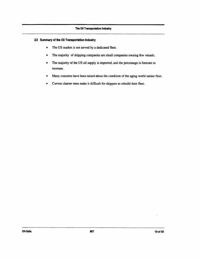
2.5 Summary of the Oil Transportation Industry
* The US market is not served by a dedicated fleet.
* The majority of shipping companies are small companies owning few vessels.
* The majority of the US oil supply is imported, and the percentage is forecast to
increase.
* Many concerns have been raised about the condition of the aging world tanker fleet.
* Current charter rates make it difficult for shippers to rebuild their fleet.
Oil-Safe. MIT 19 of 59Oil-Safe. MIT 19 of 59

011 Spills
3. Oil Spills
Mention oil spills and immediately the Exxon Valdez comes to mind. Surprisingly, the
Valdez was only the eleventh largest spill in history(Table 1). The worst accident in
history actually occurred off Trinidad and Tobago in 1979 when the Atlantic Empress
and the Aegean Captain collided, spilling an estimated 92 million gallons of oil. The
second largest took place off the coast of Cape Town, South Africa in 1983 with the
wreck of the Castillo de Beliver spilling an estimated 77 million gallons of crude. 4" 5
Table 1: Eleven Worst Oil Spills' 's
July 1 979 Tiald Atlant ic mpressAegearSpillage
August 1 978 South Africa Castillo de Beliver 77March 1978 France Amoco Cadiz 6 8DWateh Locartaion Tore ankers a 3 ns`. ............Marchme 19 7 8 l oFrac O A moc Ca di 68a
May 1 976 Spain Urquiola 31February 1977 North Pacific Hawaiian Patriot 30M1arch 17 Sw en otheo lo 18-31D~ecember 2SanAga e 2 1June 1968 South Africa World Glory 1 4March 1 989 Alaska Exxon Valdez 11
14 Wells, Ken, "International: ship spews oil after collision off Indonesia; Danish vesselcatches fire; Accident is third major tanker spill in weeks", The Wall Street Journal,January 22, 1993.15The Economist, August 26, 1989 as referenced in PDF#90-051-085.
Oil-Safe. MIT 20 of 59

Oil Spills
The Exxon Valdez was far from an isolated incident. In the 15 months following the
Valdez spill, there were four more grounding incidents spilling a total of 1.25 Million
gallons of fuel or crude oil.' 6
Between the years of 1977 and 1990 a total of 15,311 oil spills took place in US waters,
for a total volume of more than 247,000 metric tons of oil, and an average annual
volume of oil spilled of 17,700 tons, yet this was less than five percent of total world
wide oil spills. Only .6% of these spills were larger than 100,000 gallons(Figure 3.1).5
Figure 3.1: Number of US Oil Spill Incidents 1977-1990'
But these same spills were responsible for 87 percent of the total volume spilled(Figure
3.2).
16 Bobcat Engineering Corporation, "Re: Structural and Operational Measures to reduce
Oil Spills from Existing Tank Vessels without Double Hulls...", February 14, 1994,
PDF#91-045-161.
Oil-Safe.
Spills of 100,000Gallons or More
Spills99,999 Gallons
21 of 59

Oil Spills
Figure 3.2: Volume of Oil Spilled By Accident Size5
3.1 The causes of Oil Spills
Figure 3.3 shows that for tank vessels greater than 5,000 DWT, the primary cause(74.2%)
of minor spill incidents (less than 100K gallons) are operational failures, while the
primary causes of major spill incidents are groundings(40.8%) and
collisions/rammings(26.5%).
Oil-Safe. 22 of 59
Spills of 0-9,999 gallons
Spills of100.000 aallons
or more
-''' --
Oil-Safe. 22 of 59

Oil Spills
Figure 3.3: Cause of US oil spills from tankers greater than 5K DWT s
600
500
400
300
200
100
Gr ouding Collis ion/ Fire/ Structural OperatioralRamming Exlosion
10 Spills < 100K gallons E Spills greater than 100K Gallons
Figure 3.4 shows the volume of oil spilled by cause. While groundings cause only 3.5%
of the total spill incidents, they are responsible for 42.7 percent of the total spill volume.
Figure 3.4: Cause of US oil spills from tankers greater than 5K DWT5
69005
43251
23538
8403
34
Grounding Coil ision/Ramming
Fire/ StruExplosion
5775 6991
ictur al Oper ational
a Spills < 1OK gallons U Spil Is gr eater than 100K Gallo rs
Oil-Safe. MIT 23 of 59
70000-
60000
50000-
40000-
30000-
20000-
10000-
0-
Oil-Safe. MIT 23 of 59

Oil Spills
3.2 Costs of Oil Spills
Oil spills cost companies billions of dollars and raise emotional responses from the
public. Consider the consequences of the following three tanker accidents:
* Exxon's reputation still suffers after spending $3 billion dollars to clean up the
Valdez spill, and another $1 billion to settle federal and Alaskan state lawsuits. 17
* The grounding of the Aegean Sea as it tried to enter the Spanish Atlantic port of La
Coruna spilled nearly 21 million gallons of crude oil, causing losses to the fishing
industry of $50 million dollars."
* A federal appeals court raised the damages Amoco Corp. must pay for the 1978
Amoco Cadiz spill off the coast of France to $204 million from $160 million
previously awarded to various French entities.' 9
17 Solomon, Caleb, "Environment: Exxon attacks scientific views of Valdez spill ", The
Wall Street Journal, April 15, 1993.
" Wells, Ken, "Tanker, aground off Shetland islands, poses threat of an oil spill disaster",
The Wall Street Journal, January 6, 1993.
19 "Business Brief-- Amoco Corp.: Court orders oil company to pay more for 1978 spill",
The Wall Street Journal, January 27, 1992.
Oil-Safe. 24 of 59
Oil Spills
33 Summary:
* The Exxon Valdez while probably the best known oil spill was only the eleventh
largest in history.
* Although less than one percent of all spills in US waters are larger than 100,000
gallons, these large spills are responsible for 87% of the total volume of oil spilled.
* The primary causes of major spill incidents are groundings(40.8%) and
collisions/rammings(26.5%).
* Oil spills evoke a highly emotional response from the public.
Oil-Safe. 25 of 59
Oil-Safe. 25 of 59

Oil Spill Regulation
4. Oil Spill Regulation
41 Congress - Oil Pollution Act of 1990(OPA 90)
The Oil Pollution Act of 1990 was a desperate attempt by congress to appease the voting
public following the catastrophic Exxon Valdez oil spill. The Act was intended to reduce
oil pollution in US waters, so while it mandated double hulls to be phased in, Congress
had the foresight to require that alternatives also be evaluated, and to require short-term
measures to be implemented immediately.
4.1.1 The Double Hull Requirement
Section 4115(a) of the act mandated that all US and foreign flag vessels operating in US
waters that were constructed or had undergone major conversion after June 30, 1991
include a double hull, and it included a schedule to phase in double hulls on all existing
tankers operating in US waters by January 1, 2015. Table 2 shows the age of vessels that
must be phased out or converted each year.
Table 2: OPA 90 Phase-in Schedule s
195 - ~ 40 II 2 28e gg .199 3980
...
...........
1997 38 30 261998 37 29 25
000 *5 01. 232001 35 26 232002 35 26 23
2005 25 25 232006 25 232-001 25 2.
2009 232010 23
Oil-Safe. 26 of 59
Oil-Safe. 26 of 59

Oil Spill Regulation
The act also raised the liability for tanker owners and authorized unlimited liability if the
spill results from the violation of federal law - such as operation of a ship while
intoxicated. 0
Table 3 shows how double hulls would be phased in if OPA 90 applied to the world
tanker fleet.
Table 3: Potential Double Hull Retrofitting Requirement (# of vessels)"
1990 0 ........ . 281996 37 82 32 137
1997 37 82 32 137
2001 86 344 30 5132002 130 474 40 553200. 17. .52 M. .1N
2005 36 770 35 7252006 67 837 32 7572007 T:9 . . 96 8 785
2008 W . .991 . 81 22009 36 1027 33 8452010 201 1228 76 921
This table shows that only 14% of the world tanker fleet under 175,000 DWT would be
forced to cease trading by the year 1999, but as the shaded numbers highlight, 33% of the
50-175,000 DWT tankers would be affected in 1999-2000; 25% of the 10-50 thousand
DWT tankers would be affected in 1999-2000; and 34% of the total 10-175,000 DWT
tankers will be affected in the years 1999-2003.
20 Drewry Shipping Consultants.
Oil-Safe. 27 of 59

Oil Spill Regulation
4.1.2 Alternative Measures
Many alternative designs were proposed to Congress. Section 4115(e)(1) of OPA 90
required that:
the Secretary [of Transportation] shall determine, based on recommendationsfrom the National Academy of Sciences or other qualified organizations, whetherother structural and operational tank vessel requirements will provide protectionto the marine environment equal to or greater than that provided by Double Hulls,and report to Congress the determination and recommendations for legislativeaction.
The coast guard commissioned a study from the National Academy of Sciences to
evaluate the effectiveness of a number of alternative vessel designs. The NAS study
found that the double hull was the most effective at preventing outflow from low energy
collisions and groundings. However, they determined that the Mid-deck tanker would be
more effective in high-energy accidents although it might spill some oil in low-energy
accidents. Based upon these findings the NAS recommended the double hull over the
mid-deck tanker.
Finally the USCG commissioned Herbert Engineering Corporation to conduct a
probabilistic outflow analysis of several alternatives including the mid-deck and double
hull tanker designs. Herbert Engineering Corporation concluded that since the double
hull will prevent oil spillage from low-energy accidents, the majority of oil spills can be
prevented by the double hull.
Based on the results of the Herbert Engineering Corporation study, the Coast Guard
proclaimed that "no change in the present OPA legislation is recommended at this time."
4.13 Interim Requirement
Section 4115(b) of the Act requires that vessels over 5,000 gross tons that are subject to
the double hull requirement, between now and the time that they are forced to cease
trading, implement structural and operational measures that provide "as substantial
protection to the environment as is economically and technically feasible."
The Coast Guard was tasked by the Secretary of Transportation to develop these
operational and structural measures.
Oil-Safe. 28 of 59
Oil-Safe. 28 of 59
011 Spill Regulation
The USCG then developed a proposed rulemaking, which would require, within 3 years
of publication of the final rule, that all tank vessels over 5000 gross tons operating in US
waters implement one of the following':
* Double bottom or double sides; or
* Protectively located spaces; or
* Loaded only to the point of hydrostatic balance(HBL); or
* Other measures ensuring the same level of protection as PUL/Spaces.
A notice of proposed rulemaking(NPRM 91-045) was published in the Federal Register,
initiating a comment period. During this period comments were received from concerned
groups such as proponents of new designs, shipping companies, tanker owners, insurance
industry representatives, and environmental groups.
The Coast Guard then commissioned Mercer Management Consulting Company to
perform an Interim Regulatory Impact Analysis of Structural and Operational Measures
for existing tank vessels.
This report is a crucial source of data to anyone preparing a submission to the coast guard
for approval of an alternative design, because it is what the coast guard has publicly
accepted as the facts.
There seems to be a political agenda at the Coast Guard to discredit all alternatives put
forth and save face for congress over a premature decision to require double hulls. In the
words of a senior Coast Guard official speaking off the record, "No alternative design
will ever be approved." 21
21 Phone conversation with senior Coast Guard official, December 1994.
1Oil-Safe. MIT 29 of 59

Oil Spill Regulation
4.2 The International Maritime Organization(IMO)
The International Maritime Organization(IMO) is part of the United Nations. The IMO is
made up of the world's major seagoing nations. The IMO was formed to promote global
maritime safety and environmental protection. Annex I of the International Convention
for the Prevention of Pollution from Ships (1973,1978) or MARPOL requires that certain
tankers have PL/Spaces or SBT's arranged to protect approximately 30 to 45% of the
hull, as well as other regulations to minimize potential outflow. It is estimated that 17%
of tankers over 10,000 DWT are compliant with MARPOL. The Exxon Valdez was
compliant with MARPOL.
The IMO then conducted a comparative study of the effectiveness of the mid-deck tanker
versus the double hull. The IMO used a different measure, deciding that the most
important measure was the total oil outflow prevented for all accidents. They concluded
that the Mid-Deck was at least as effective as the double hull at reducing total oil
outflow.
In March 1992, the IMO decided all tankers bigger than 50,000 tons should have a
double hull to prevent crude oil from leaking in an accident. The IMO requested that
member countries apply the decision to new tankers ordered after July 1993 and
completed after July 1996. The plan would also require the replacement of all existing
single-hull tankers larger than 20,000 tons when they become 25 years old. 2
Under the IMO plan, 350 of the 437 single hull VLCC's in operation in 1991 will have
operated for 25 years and thus will need to be scrapped between 1995 and 2004. 12
Oil-Safe. 30 of 59
Oil-Safe. 30 of 59

011 Spill Regulation
4.3 The European Community (EC)
The 12 nation European Community is considering establishing a tanker registry to keep
tabs on the quality of ships using EC waters and placing a ban on ships older than 15
years. The ban, should it be adopted, would keep about 40% of the EC's own ships from
Common Market ports.'o
4.4 Regulatory Impact on Industry
The impact of new regulations on industry will be significant. It is estimated that the
annual costs of shipping oil to the US will rise between $462 million and $2.05 billion
dollars under OPA 90.22 This section will show how many tankers will be directly
impacted by the new US and IMO rules, the impact on fleet capacity when shippers are
forced to stop serving the US market because they can not meet the requirements of OPA
90, and how all shippers will be affected.
4A.1 Vessels Impacted
The world tanker fleet will be directly impacted by the new US and IMO rules. As
explained in Section 2: The Oil Transportation Industry, the US is served by a large fleet
of non-dedicated tankers. The minimum number of vessels that could be impacted by
OPA 90 would be the full-time equivalent number of tankers serving the US (600 in
1990). These tankers must immediately retrofit an interim solution as described above in
Section 4.1, and must retrofit a double hull or be scrapped according to the schedule in
Table 2: OPA 90 Phase-in Schedule.
The IMO rule will require all tankers to retrofit a double hull or be scrapped when they
become 25 years old.
22 Hopkins, Thomas, "Oil Spill Reduction and costs of ship design regulation",
Contemporary Policy Issues, July 1992.
bil-Safe. 31 of 59

Oil Spill Regulation
4A.2 Fleet Capacity
Mercer Management Consulting performed an analysis to determine how cargo capacity
to the US will be affected by the removal of vessels from US service and the reduced
cargo carrying capacity of the vessels that remain in service. There is uncertainty what
will happen to second-hand tanker values, as the purchaser would be faced with the same
retrofit problem as the seller. If the resale value is high, then selling the existing vessel
and purchasing a new vessel is more attractive, while if the resale value is the scrap value
for the tanker, owners are more likely to modify their existing vessel. Two scenarios
were analyzed: a minimum impact that assumes vessels can only be resold at scrap value
and a maximum impact assuming tank vessels will have full second-hand value. As
Figure 4.1 shows, the effect of requiring modifications will reduce the international fleet
capacity serving the US from 5% for the minimum impact of implementing PL/Spaces or
SBT to 100% for the maximum impact of implementing double bottoms5.
Figure 4.1: International Fleet Capacity Reduction of Proposed Modifications s
Oil-Safe. 32 of 59
100%
80%60%40%20%0%.9
E
PL/ Double Double HBL Oil-Space Sides Bottom Safe/SBT
SMax Min
Oil-Safe. 32 of 59

Oil Spill Regulation
Currently, the US import trade employs approximately 21% of the world tanker fleet, a
10% reduction in the international fleet serving the US would remove approximately
2.1% of the world fleet. ' To understand the impact of this reduction, one must consider
how would the capacity be replaced?
The only possible source of replacement capacity would be the tankers currently laid up
or inactive. But, as Figure X shows, there is barely enough excess capacity to make up
the reduction in cargo capacity to the US created by the least expensive options,
PL/spaces, SBT, and Oil-Safe23. There would not be enough capacity to make up the loss
created by HBL, Double sides, or double bottom.
Figure 4.2: Tankers Inactive or Laid-Up 1992 (M DWT) 5
100%0%-
90%
0%-80%
0%-70%
30% -60%50%0%30%20%
1 0%
0%
_ Laid-Up
3 Active
Foreign Flag
23 Assumes Oil-Safe will cost no more than PL/Spaces.
262.6
7.1
I -
*
U.S. Flag
-._ .
Oil-Safe. 33 of 59

011 Spill Regulation
4.A3 Shippers
Shippers are directly impacted by OPA 90. Here is a sampling of the impact of OPA 90:
* OPA 90 increases the liability for owners of an average sized supertanker operating
in US waters to $100 million from the previous IMO regulation level of $14
million.'o
* Ship hull insurance and protection and indemnity costs have risen2 4
* Tank vessels of more than 3,000 gross tons are required to provide proof of financial
responsibility of $1,200 per gross ton or $10 million, whichever is greater. 25
* Insurance premiums have nearly doubled.25
* The threat of higher liability has raised freight rates as much as 10%25
* London hull insurance rates are already 25% higher, and cargo rates are 10 times
higher.'o
24 Macalister, Terry, "Changes at Sea", International Management, March 1992.
25 Anderson, Charles, "Oil pollution act fouls regulatory waters", The Wall Street
Journal, February 20, 1992.
Oil-Safe. MIT 34 of 59

The Double Hull Oil Tanker
5. The Double Hull Oil Tanker
The concept of the double hull oil tanker is that by adding a second hull spaced some
distance away from the exterior hull, any penetration will have to pierce two hulls instead
of one. Figure 5.1 shows a cross-section of a typical double hull oil tanker.
Figure 5.1: A Typical Double Hull Cross-Section
The hull separation distance was determined by surveying the penetration depths in
numerous accidents. As specified by OPA 90 the separation distance is the lesser of:
* B/15 or at a minimum, 1.0 meters; or
* 2.0 meters
where B is the beam or width of the vessel.
Oil-Safe. MIT 35 of 59Oil-Safe. MIT 35 of 59

The Double Hull Oil Tanker
A double hull increases the cost of a new vessel by an estimated 20%.12 Retrofitting an
existing vessel with an inner hull is estimated to cost between (20% to 50%) of a new
vessels' cost, prompting the National Academy of Sciences to declare retrofitting a
double hull economically unfeasible. 26
Numerous concerns have been raised about the process with which the double hull was
selected as the solution of choice, the actual effectiveness of the double hull, the poor
performance of the double hull once breached, and the inherent danger of the double hull.
5.1 The Double Hull Selection Criteria
The justification for the selection of the double hull as presented in Section 4.1.2 was that
it will eliminate oil spillage from the vast majority of accidents, e.g. low energy collisions
and groundings. Unfortunately, looking back to Figure 3.2 we see that while the vast
majority of accidents are low-energy, the majority of oil spilled is from the few high
energy accidents in which the double hull will probably be breached and spill more oil
than a single hull would have(see below).
5.2 The Double Hull Effectiveness.
The double hull may not be as effective in low-energy accidents as assumed.
The Herbert Engineering Analysis was a probabilistic analysis, examining an extensive
database of penetration depths, and concluding that spillage from any accident having a
penetration depth less than the 2 meter separation distance of the hulls of the double hull
would have been completely prevented by the double hull tanker. This assumption
completely neglects the large scale deformation, plate buckling, and weld failure that will
occur in a high energy collision.
Finite element analysis has raised concerns that the inner hull can collapse in the event of
minor damage to the outside shell due to high compressive loads on the interior hull
resulting from the double hull construction.27
26 National Academy Of Sciences, Tanker Spills: Prevention by Design
27 Bjorkman, Anders B., "Re: Comments on OPA 90 Double Hull Requirements",
February 5,1993, PDF#90-051-136.
Oil-Safe. MIT 36 of 59

The Double Hull Oil Tanker
5.3 Once breached, the Double Hull will spill more Oil than a single hull.
The Mercer Management Consulting Environmental assessment performed for the USCG
states that the double hull is actually 33% less effective than the single hull at preventing
oil spillage in collisions of small vessels, and only 51% more effective than the single
hull in collisions of large vessels.7
Cargo sits higher in the water in a double hull tanker, thus upon rupture more oil must flow out toestablish hydrostatic balance. If the Exxon Valdez had been of double hull construction an
estimated 70,000 additional barrels of oil would have been spilled .28
Not only will ruptured tanks leak more of their cargo, but more tanks will be at risk due
to the increased probability of bulkhead rupture. The double hull with its additional
bracing required to maintain the separation of the two hulls has a much greater shear
strength. Thus in the event of a grounding or collision, less energy will be dissipated in
crumpling inwards of the hull, and more energy will be transmitted in shearing forces
longitudinal to the tankers' axis, which may result in the rupture of bulkheads away from
the ruptured tanks, thus allowing many more tanks than the penetrated one to leak their
cargo to the sea.28
In the event of exterior hull rupture, the void space between the two hulls will fill with
liquid, possibly causing the vessel to sink, but definitely reducing seaworthiness.
5.4 Double hull tankers have inherent risks.
Vapors may accumulate in the free space between the hulls, creating a risk of fire and
explosion. Hydrocarbon vapors in the free space of double bottom tankers have
exploded.
28 Fuess, William C., "Re: Comments on Proposed Double Hull Standards for Vessels
Carrying Oil In Bulk...", February 24, 1993, PDF#90-051-140.
Oil-Safe. 37 of 59

1Oil-Safe Design
6. Oil-Safe Design
Oil-Safe is a retrofittable multi-component liner system based on a simple observation:
there will be high energy collisions and groundings that a ship will not survive. A system
designed to keep the hull intact will fail. Oil-Safe was designed to maintain cargo
integrity and ship seaworthiness even in the event of hull compromise, containing the oil
within the hold by safely and simply moving out of the way of any impinging objects.
The motivation for the Oil-Safe design is to fill a market need. Every step of the design
process to date was guided by the understanding that the design will never leave the
drawing board unless it:
* Provides better protection to the environment than the single or double hull;
* Is quickly and easily retrofittable - time in retrofit carries an opportunity cost of
$10,000 for each day a 140,000 DWT tanker is not in service3 ;
* Is low cost.
By focusing on the market throughout the process, a system has been designed to address
all the above concerns, providing a technically and economically feasible solution to the
tanker oil spill problem.
Oil-Safe. MIT 38 of 59Oil-Safe. MIT 38 of 59

Oil-Safe Design
6.1 Oil-Safe System Overview
Figure 6.1 illustrates the Oil-Safe concept in cross-section. A flexible, impermeable
membrane separates the oil from the base of the cargo hold. The membrane is supported
above the hold's structural element by a layer of rigid foam equal in thickness to the
spacing between double hulls. The barrier is attached to and sealed against the sides of
the hold, but has no structural influence on the hold or the vessel.
Figure 6.1: Center Cargo Tank Oil-Safe Installation
The Oil-Safe system will provide greater protection to the marine environment than that
provided by either single hull or double hull vessels.
In describing how the design works it is helpful to define two types of accidents. Type I
accidents where the penetration depth is less than the hull separation of a double hull
tanker (typically 2 meters),, and Type 2 where the penetration is greater.
Oil-Safe.
Original Center Cargo Tank
MIT 39 of 59
I. .I

0i1-Safe Design
Type 1 Accidents:
It is estimated that of the large vessel grounding incidents studied that result in oil
spillage, 98% have experienced a penetration depth less than the double hull separation
distance, and all small vessel grounding incidents have resulted in a penetration depth
less than the double hull separation.29
Thus, in the event of a hull penetration, in the vast majority of incidents, the penetration
depth will be less than the thickness of the foam foundation of the Oil-Safe design.
In this case, there will be absolutely no risk of oil loss from a tanker retrofitted with the
Oil-Safe design. The impinging object will gash the hull but will not reach the Oil-Safe
membrane though it may harmlessly deflect it. Further, since space between the exterior
hull and the membrane is filled with closed cell foam, water will not enter. The ship will
remain seaworthy.
Type 2 Accidents:
It is estimated that of the large vessel collision incidents that result in oil spillage, 49%
have a penetration depth greater than the double hull separation distance, and all small
vessel collision incidents result in a penetration depth greater than the double hull
separation.29
In the event of a penetration depth greater than the thickness of the foam, the offending
obstacle will rip apart the hull, deforming steel plate and dissipating energy as it passes
through the foam. It will reach the membrane and move it and cargo inward out of
harm's way, until the tanker comes to a halt.
Without performing more detailed analysis, it is impossible to say what percentage of
Type 2 accidents will be survived by the Oil-Safe system, but it is possible to say with
certainty that the design will survive some Type 2 accidents, thus far surpassing the
effectiveness of the double hull, currently the only accepted solution, as the double hull
will not survive all Type I accidents(see Section 5: The Double Hull Oil Tanker for
details) and the double hull, by definition, will not survive any Type 2 accidents.
29 Analysis of information in reference #5.
1Oil-Safe. MIT 40 of 59

Oil-Safe Design
The Oil-Safe system is made up of:
* A foam foundation.
* Mounting brackets.
* A reinforcement curtain.
* And a neoprene liner.
In the sections that follow the conceptual design' of each of these components is
described.
o The design of the system has been completed to the level of detail necessary to
demonstrate the feasibility of the concept and to apply for a patent.
Oil-Safe. 41 of 59
Oil-Safe. 41 of 59

Oil-Safe Design
&2 Foam Foundation
A rigid, closed-cell foam foundation is placed between the hull and the membrane.
Figure 6.2: Foam Foundation.
Functional Requirements:
* Transfer the weight of the liquid cargo from the membrane to the hull, with
minimum modification of existing structure and piping;
* Hold the membrane away from the internal structure of the cargo hold;
* Space the membrane liner safely away from interaction with gashed edges of the
hull. Any penetration that is less than the thickness of the foam will have no contact
with the membrane or cargo.
Oil-Safe. 42 of 59
Oil-Safe. 42 of 59

Oil-Safe Design
Foam Foundation Design:
The foam foundation is poured into the hull and sets in place to become a high
compressive strength, closed cell structural foam. All corners are filleted.
Component Benefits:
* Easily installed, with minimal hull preparation.
* Depending on the foam used and hull condition, it may be possible to pour the foam
directly into a hold without any surface preparation work;
* Transfers the load from the membrane to the hull without rigidly attaching the two.
The membrane "floats" free of the hull and exerts no structural influence on the ship
design;
* Provides buoyancy and prevents the entry of liquids into the space between the
membrane and hull in the event of hull compromise;
* Low cost - requires no steelwork, little time to install, no welding;
* Provides a smooth surface for the membrane to rest on - covers all the internal
structure within a typical vessel cargo tank;
* Lightweight.
Oil-Safe. 43 of 59
Oil-Safe. 43 of 59

Oil-Safe Design
6.3 Membrane
The membrane is a two-layer construction, an upper impermeable layer and a lower
reinforcement curtain to protect the former from local penetration.
63.1 Impermeable Upper Layer - Membrane Liner
An impermeable membrane is used to contain the liquid cargo.
Figure 6.3: Membrane Liner
Functional Requirements:
* Directly contact the liquid cargo - without breaking down or reacting;
* Contain the cargo;
* Withstand flexing of normal operations and, when necessary, of hull penetrations.
1/4" Neoprene
·
Id Nylon
Oil-Safe. MIT 44 of 59

01i1-Safe Design
Membrane Liner Design:
The membrane liner is made of 1/4" neoprene, reinforced with 14 oz/yd nylon for greater
than 1000 lbs/inch breaking strength. In the development of this design, a series of
reports was discovered in the MIT archives that was the result of a million dollar
government funded research effort to develop membranes to install in oil tankers to
separate ballast from oil within cargo tanks. The study included experiments, analyses,
life testing, and material compatibility studies. The conclusion of the study was that a
1/4" Nitrile or Neoprene membrane reinforced with 14 oz/yd nylon would last 10 years
under constant flexing and in contact with the rough metal edges of the interior structure
of an oil tanker. Thus it is safe to estimate the useful life of a liner in service on the foam
foundation at 10 years.
Component Benefits:
* Low cost;
* Inert;
* Designed for pre-fabrication;
* Proven performance.
Oil-Safe. 45 of 59
Oil-Safe. 45 of 59

Oil-Safe Design
63.2 Reinforcement Curtain
The impermeable upper layer is supported and protected by a separate reinforcement
curtain.
Figure 6.4: Reinforcement Curtain.
Functional Requirements:
* Support the impermeable layer;
* Withstand all encounterable blunt impacts and ripping impacts.
9/16" Wire Rope Woven into Mat16.4 tons breaking strength/Rope
Oil-Safe. MIT 46 of 59

1Oil-Safe Design
Reinforcement Curtain Design:
The reinforcement curtain is woven out of closely spaced 9/16" wire rope with
continuous loops formed at the edges of the curtain allowing for suspension. The
breaking strength of each rope is 16.8 tons.
In the course of preliminary design work, the reinforcement curtain has undergone
numerous design revision. The original specification was for an extremely tough
material. Blasting mats, used to contain debris from blasting, were considered for their
assumed toughness and strength. After discussions with blasting mat manufacturers, it
became apparent that blasting mats are very expensive, and not very strong.
An American manufacturer was found who was willing to enter an OEM relationship to
weave mats of 9/16" steel rope which is the largest diameter of steel rope that can be
woven.
Other possible materials for the reinforcement curtain might be chain mail or Kevlar
fabric.
Component Benefits:
* Flexible - can avoid high forces by moving out of their way;
* Easy installation;
* High strength and toughness.
Oil-Safe. MIT 47 of 59Oil-Safe. MIT 47 of 59

Oil-Safe Design
64 Mounting Brackets
The membrane is attached at its upper edge to the inside wall of the cargo tank.
Figure 6.5: Mounting Bracket
RubberSiWeld
Clamping Block
Nut-
NeopreneLiner
Washer
Hard RubberBlock
ReinforcementCurtain ___
Mounting Bolt
4------- Hull
Mounting Bracket
Functional Requirements:
* Structurally support the membrane;
* Provide a liquid tight seal between the liner and the hold;
* Protect the membrane liner from mechanical damage.
Oil-Safe. 48 of 59

Oil-Safe Design
Mounting Bracket Design:
The brackets are repeating sections attached to the tank sides surrounding the perimeter
of the interior walls of the cargo hold. Bolts protrude through a mounting plate which is
welded to the interior tank walls. The reinforcement curtain is bolted to the plate and
held in place by a nut, washer, and hard rubber block which prevents all metal edges from
contacting the neoprene liner. The liner is sandwiched between rubber seals and clamped
with angle stock.
Component Benefits:
* Simple design;
* Low parts count;
* Designed for pre-fabrication;
* Quick and inexpensive installation.
Oil-Safe. 49 of 59
Oil-Safe. 49 of 59

Oil-Safe Design
6.5 The Oil-Safe Design Process
The design underwent a lengthy cycle of review and modification, during which it
evolved into a unique, technically and economically feasible solution to the world
problem of spills from oil tankers.
The motivation that initiated the Oil-Safe project was to provide a flexible barrier
surrounding tanker cargoes that will resist penetration in collision and grounding by
moving out of the way. The original concept called for a Kevlar reinforced bladder to
completely surround the oil within each hold of a vessel.
Design reviews by professors in marine and mechanical engineering design suggested
that in the event of a collision or grounding, the edges of the hull gash have numerous
inwardly pointing shards of steel, that might penetrate a Kevlar fabric. This led to the
idea of a multi-component protection system, with a single component, the reinforcement
curtain, designed specifically to protect the liner from interaction with the hull gash and
to diffuse the concentrated local loads over a broader area.
Additional review by investors and experts in the shipping industry indicated that the
closed bladder design would not be economically feasible. This led to the realization that
it is not necessary to surround the entire cargo with expensive material, as the
containment is only in danger at the sides and the bottom of the tank. By providing
protection only where required the design is economically feasible. This realization led
to a new design, completely different from the nearly 100 existing patents on tanker liner
designs.
One of the primary problems with all liner designs is the need for a
periodic(approximately every 5 years) visual inspection of the condition of the interior of
the hull.26 The Oil-Safe system is designed for easy removal and replacement of the
membrane and the foam can be washed out with high pressure water and replaced after
inspection. A new type of sensor is in development that will use eddy-currents and/or
ultrasound to determine the condition of the hull without visual access' 6 which may make
it possible to inspect the hull without disturbing the Oil-Safe system.
Oil-Safe. MIT 50 of 59Oil-Safe. MIT 50 of 59

Installation
7. Installation
One of the primary goals of Oil-Safe was that it be quickly and inexpensively installed.
The design has a number of features that help accomplish this goal:
* Minimal hull surface preparation work is required;
* No structural steel work is required;
* No dry-dock is required;
* Low parts count;
* Simple, easily fit attachment system;
* Design for manufacture/installation;
* Design allows for prefabrication of all components.
Thus the installation of an Oil-Safe system in an existing single hull vessel can be simple,
inexpensive, and quick.
Figure 7.1 shows a typical center cargo tank of an existing vessel, before installation of
the Oil-Safe system. The hull is reinforced with longitudinal bracing and the center web
frame. The walls may be covered with oil residue from years of service.
Oil-Safe. 51 of 59
1Oil-Safe. 51 of 59

Installation
Figure 7.1: A typical center cargo tank.
r -
The process to retrofit a typical tanker hold such as this one are described in detail in the
following sections.
Oil-Safe. 52 of 59
InstallationFigure 7.1: A typical center cargo tank. _
i
-- -~II ~ ~L -J - I-
l immll
Oil-Safe. 52 of 59

Installation
7.1 Surface Preparation
Typically, for any modification work that is performed on a tanker, the tanks require
some amount of surface preparation work. This will range in the minimum from a water
cleaning of the tank to a maximum of sandblasting, priming, and two coats of epoxy.
The Oil-Safe design however, only requires a two foot strip be cleaned around the
perimeter of the hold to prepare for the welding of the mounting brackets. No other
surface preparation work is required, although a simple water cleaning at a cost of
$9,000/tank may be desired. This feature alone saves up to $500,000. Figure 7.2 shows
the center cargo tank after surface preparation work is completed.
Figure 7.2: Surface Preparation
r r r r
Oil-Safe. 53 of 59
-- I
f
- I I - -I - · C~
l m
1Oil-Safe. 53 of 59
MM _ _

Installation
7.2 Brackets
The mounting brackets are prefabricated off site in strips. The strips are lowered into the
hold by crane, with bolts in place. Next they are welded into place at the desired height
(presumably at the accepted double hull separation distance)see Figure 7.3.
Figure 7.3: Bracket welding.
r r
Oil-Safe. 54 of 59
r
- I
MIll a
1Oil-Safe. 54 of 59

Installation
7.3 Foam Foundation
Once the brackets are in place, the foam placement can begin. One of the primary
benefits of using a layer of foam to support the liner system instead of structural steel
work is that a liquid foam will conform to the existing structure automatically, whereas
steel needs to be shaped, fitted and welded into place, a very expensive and time-
consuming process. The foam is piped in and covers the internal structure up to the
desired depth(Figure 7.4: Laying the foam foundation. Forms can be used to build the
foam up to cover the center web frame, but they may not be needed because the desired
shape might be made by proper application of the foam. A smooth shape is desired, but
precise dimensions are not necessary.
Figure 7.4: Laying the foam foundation.
Oil-Safe. ~rr 55 of 59Oil-Safe. MIT 55 of 59

Installation
7.4 Reinforcement Curtain
The curtain is fabricated off site to match the dimensions of each hold. A crane lowers
the curtain into the hold, where it is hung over the lower set of protruding bolts. Next
strips of hard rubber block, and washers are placed over the bolts. Finally, the curtain is
bolted into place with pneumatic wrenches.
Figure 7.5: Installing the Reinforcement Curtain.
Oil-Safe. MIT 56 of 59Oil-Safe. MIT 56 of 59

Installation
7.5 Membrane Liner
The Oil-Safe system is completed with the installation of the membrane liner. The liner
is fabricated off site to match the dimensions of each hold. A rubber seal is placed over
the upper set of bolts. A crane lowers the liner into the hold, where it is hung over the
bolts. Next the second rubber seal and a compression angle are placed over the bolts.
Finally, the compression angle is bolted into place with pneumatic wrenches, tightening
sufficiently to assure an oil-tight seal between the liner and the tank wall.
Figure 7.6: Liner Installation.
Oil-Safe. MIT 57 of 59Oil-Safe. MIT 57 of 59

Conclusion
8. Conclusion
The Oil-Safe system, a retrofittable multi-component liner design, will provide greater
protection to the marine environment than either the single hull or double hull tanker
designs, by moving out of the way of intruding penetrations while maintaining cargo
integrity. In type 1 accidents, where the penetration depth is less than the double hull
separation distance, there is no risk of spillage from the Oil-Safe system, but there is a
risk of spillage from a double hull due to structural failures. In type 2 accidents, where
the penetration depth is greater than the hull separation distance, the double hull, by
definition will spill oil, while the Oil-Safe design may survive with all cargo intact. Not
only will the system survive more accidents than the double hull or single hull, the oil-
safe system can be economically retrofitted on existing vessels putting it within reach of
the vast majority of tanker operators: the small fleet operators who may not be able to
afford a new double hull vessel.
For these reasons, a single hull vessel retrofitted with the Oil-Safe system in all tanks is
proposed as an alternative to the double hull. A single hull retrofitted with the Oil-Safe
system in 30% of the tanks is proposed as an alternative to the PL/Spaces requirement.
While the IMO has shown that their primary consideration in tanker design regulation is
protection of the environment, the USCG has shown that they are a highly political
bureaucracy that feels independent of the democracy which created it. Their intent seemsto be to implement the letter of OPA 90, with no regard for the intent of the law, whichwas originally created to provide greater protection to the environment from oil spills.
Something needs to change when the system to select the best protection for theenvironment is run by bureaucrats instead of engineers, who give equal or greater weightto pleas from entire classes of ten year olds living in Alaska with hundred pagesubmissions describing alternative designs from engineers with decades of experienceand industry support.
Oil-Safe. MIT 58 of 59

Conclusion
The only consolation to the many minds working on alternative designs is that the public
may find out one day soon what many have long suspected, that the double hull is not the
best available protection for the environment.
In the words of Attorney William C. Fuss writing in support of the American
Underpressure System, an alternative design to the double hull,
If the USCG does not provide.., for even the possibility of an alternative, orcomplimentary, system to the double hull, then the USCG is surely putting all itseggs in one, double-hulled, basket28.
Oil-Safe. SOot 59
Oil-Safe. 59 of 59