Embed Size (px)
Citation preview
University of Arkansas, FayettevilleScholarWorks@UARKBiological and Agricultural EngineeringUndergraduate Honors Theses Biological and Agricultural Engineering
8-2008
Design of a temperature profiling system for use inthermal processing of food productsLinda TarantinoUniversity of Arkansas, Fayetteville
Follow this and additional works at: http://scholarworks.uark.edu/baeguht
This Thesis is brought to you for free and open access by the Biological and Agricultural Engineering at ScholarWorks@UARK. It has been accepted forinclusion in Biological and Agricultural Engineering Undergraduate Honors Theses by an authorized administrator of ScholarWorks@UARK. Formore information, please contact [email protected].
Recommended CitationTarantino, Linda, "Design of a temperature profiling system for use in thermal processing of food products" (2008). Biological andAgricultural Engineering Undergraduate Honors Theses. 16.http://scholarworks.uark.edu/baeguht/16
brought to you by COREView metadata, citation and similar papers at core.ac.uk
provided by ScholarWorks@UARK

University of Arkansas
College of Engineering
Biological & Agricultural Engineering Department
BENG 451VH - Honors Thesis
Design of a temperature profiling system for use in thermal
processing of food products
Presented by:
Linda Tarantino
Committee:
Dr. Carl Griffis
Dr. Julie Carrier
Dr. S. Bajwa
August 8th, 2008

1
Table of Contents
1. Introduction. ..................................................................................................................................... 3
2. Objectives & Constraints. ................................................................................................................ 5
3. Potential Solutions. ......................................................................................................................... 6
3.1 Storage and data acquisition: ............................................................................................. 6
3.2 Housing: ............................................................................................................................. 7
3.3 Insulation: .......................................................................................................................... 7
4. Preliminary Design ......................................................................................................................... 9
4.1 Circuit blueprint ................................................................................................................. 9
4.2 Further details of preliminary design: ................................................................................ 9
5. Final Prototype. ............................................................................................................................. 11
5.1 Cost Analysis. .................................................................................................................. 12
6. Testing............................................................................................................................................ 13
6.1 Prototype testing .............................................................................................................. 13
6.2 Bacteria testing................................................................................................................. 14
6.2-1 Material & Methods.......................................................................................... 15
6.2-2 Bacterial inoculation and product preparation: ................................................ 16
6.2-3 Bacterial enumeration: ...................................................................................... 16
7. Results & Discussion: ................................................................................................................... 17
8. Conclusions. .................................................................................................................................. 18
8.1 Some suggestions for further work. ................................................................................. 19
9. Acknowledgments.......................................................................................................................... 20
10. References .................................................................................................................................... 21

2
Table of figures
Figure 1: EL-USB3 Data logger .......................................................................................................... 6
Figure 2: Preliminary Design with ceramic housing and insulation .................................................... 8
Figure 3: Sketch and picture of circuit blueprint ................................................................................. 9
Figure 4: Preliminary design. ............................................................................................................. 10
Figure 5: Testing Insulation for Preliminary prototype ..................................................................... 10
Figure 6: Final Prototype ................................................................................................................... 12
Figure 7: Initial testing. Stein oven at the pilot plant and testing set up ............................................ 13
Figure 8: Internal temperature of the device being tested in the Stein oven...................................... 14
Figure 9: Thermal processing of contaminated chicken breast ......................................................... 17
Figure 10: Cooked product being measured as soon as it has left the oven. ..................................... 18
List of Tables
Table 1: Manufacturer’ specifications of EL-USB3 data logger (Lascarelectronics.com) ................................ 7
Table 2: Cost analysis of the final prototype. .................................................................................................. 12
Table 3: Comparison of temperature measurements of the chicken breast samples taken at the end of their
cooking process. ............................................................................................................................................... 18

3
1. Introduction.
In the last decades, people have become more dependent on ready to eat (RTE) products that
are cooked in processing establishments, not by the direct consumer. These RTE meat and poultry
products were defined by the United States Department of Agriculture – Food Safety and Inspection
Service as “products that have been processed so that they may be safely consumed without further
preparation by the consumers; i.e., without cooking or application of some other lethality treatment
to destroy pathogens” (USDA-FSIS, 2001).
The market for RTE meat and poultry products is rapidly increasing. Consequently, it
becomes more and more important to ensure the food safety of these thermally processed retail
products. Recent recalls on these RTE products, and foodborne related illnesses have led to serious
concerns over the safety of these products (CDC 2000; FSIS-USDA 2004). Therfore, the primary
concern of food manufacturers today has become the production of safe food, free of foodborne
pathogens.
Fortunately, thermal processing is an effective means of eliminating food borne pathogens
from meat and poultry products (Murphy et al., 2002). Thermal destruction of pathogens is a time-
temperature dependent process. The time-temperature relationship of thermal inactivation of
pathogens known as lethality is expressed in terms of D- and z-values. The D-value is defined by
the time required to cause 90% of reduction of the microbial population at a specific temperature.
The z-value is the temperature difference required for the thermal inactivation curve to cause one
logarithmic reduction (Murphy et al., 2004). From a known z-value, process lethality (L) can be
calculated as:
dtLz
refTtTt
−
∫=
)()(
0
10
where T(t) is the product temperature at time t, and T(ref) is a reference temperature. The z-
value should be known in order to calculate the process lethality during cooking, and it is calculated
from known D-values at different temperatures (Doyle and Mazzotta, 2000).
The USDA-FSIS (1999) recently made final pathogen reduction performance standards
applicable to the production of certain meat and poultry products. The performance standards
establish a requisite reduction of Salmonella (lethality) in certain ready-to-eat products and limit the

4
growth of spore forming bacteria of concern (stabilization) in certain ready-to-eat and partially-
cooked products. To achieve the lethality performance standard, food processing establishments are
required to achieve a 7-log10 reduction in Salmonella in ready-to-eat poultry and a 6.5-log10
reduction in Salmonella in ready to- eat beef products (Murphy et al., 2002).
To help food processors meet this regulation, USDA-FSIS issued a guideline that cooked
poultry products should reach an internal temperature of at least 165°F before being removed from
the cooking medium (USDA-FSIS, 2006). However, production volumes typically exceed 100
pounds per minute, so when products are in a small size, less than 1% of the product items are
actually being inspected.
To calculate the process lethality it is necessary to know the change in the internal
temperature of the product throughout the entire cooking process. To achieve this, food processors
need to have a device that can record temperature measurements and withstand the harsh conditions
in the oven during the whole cooking process. However, current industrial practice is to sample a
small fraction of cooked meat and poultry temperatures by inserting a food thermometer into the
meat immediately after cooking (Richardson, 2004).
The purpose of this study was to develop a thermal inspection system on a full scale meat
and poultry product line. The system must withstand the production and sanitation environments
and adapt to the many different products and conditions present on a common product line. By
using this device, food processors will be able to measure the internal temperature of the product
during its entire cooking process. This will provide certainty to food processors if the product
reached the required internal temperature by USDA standards as well as proof of their processes.

5
2. Objectives & Constraints.
The design should comply with the following characteristics:
• The device is to be a data-logging system designed to transit through industrial ovens, along
with the product being processed.
• The data logger should be protected from the extreme temperatures of the process.
• It should be appropriate for climate and working conditions
• It should be simple to manufacture and repair.
• Its handling should be safe for the operator.
• Its dimensions should be in accordance with the 3.75 in. maximum height of entrance and
exit of the Stein oven at the pilot plant in the University of Arkansas.
The following constraints must be met by the design:
• The internal temperature of the device should range between -25°C and 80°C to keep safe
the circuit connections.
• The smaller the size of the data logger the better.
• The data logger battery life should last a minimum of 6 months.
• The data logger memory capacity should be big enough to record 8 hours of processing.
• The data logger should have a USB connection so data can be easily transferred into a
computer.
Once a working prototype of the device is built, testing on reading the internal temperature
of meat product should be performed as well as testing for providing proof of bacteria destruction
on meat or poultry products through thermal processing.

6
3. Potential Solutions.
Of the many transducers available for temperature-measurement applications,
thermocouples are among the most common. They are cost effective, have standard connectors, and
can measure a much wider range of temperatures than other sensors like resistance temperature
devices (RTDs), thermistors, and temperature-sensing integrated circuits (ICs) (Carstens, 1993).
Thermocouples are constructed with two wires made from different metals.
When these two metals are joined (i.e., welded or soldered) to form two junctions, the voltage
generated by the loop is a function of the temperature difference between the two junctions (hot and
cold junctions). Knowing both the temperature of the cold junction and the temperature of the hot
junction relative to the cold-junction temperature, the actual hot-junction temperature can be
determined. To facilitate this, a cold junction compensation device can be used (Carstens, 1993).
Analog Devices Inc. (www.analog.com) offers the AD595 amplifier and thermocouple cold
junction compensator on a monolithic chip. It is intended for use with a Type K thermocouple,
which consists of the alloys chromel and alumel. The AD595 chip is capable of creating an output
voltage that is linearly related to the temperature of the thermocouple junction. For even greater
convenience, the output voltage is by default set to 10 mV/oC. Thus, voltage readings can be
converted to temperature (°C) by multiplying the value times 100.
3.1 Storage and data acquisition: Lascar electronics (www. lascarelectronics.com) offers a data
logging system known as EL-USB3 (see figure 1) and it measures and stores up to 32,510 voltage
readings and can transfer the stored data by plugging the module straight into a PC's USB port.
The data logger comes with the EasyLog USB software application, which facilitates the transfer of
the data from the logger into the computer. Once the data is transferred from the data logger, the
software allows the user to transfer the data to different software applications.
Figure 1: EL-USB3 Data logger (lascarelectronics.com)

7
Table 1: Manufacturer’ specifications of EL-USB3 data logger (Lascarelectronics.com)
Specifications Minimum Typ. Maximum Unit
Internal Resolution - 50 - mV d.c.
Accuracy - ±1 - %
Logging Rate Every 1 second - Every 12 hours -
Operating Temperature -25(13) - +80(176) °C(°F)
3.2 Housing: The housing of the device must protect the data logger, the AD595 chip and the
circuit components when subjected to thermal processing. Therefore, the housing of the circuit
should be able to withstand the harshest industrial cooking environments and therefore have high
heat resistance. It should also provide sufficient space for the wiring, and be in accordance with the
established dimensions for the device. For food applications, housings are often made of stainless
steel; however, housings made of ceramic represent an advantage since they are very good heat
insulators. For this reason, the housing of the device is to be made out of ceramic with the
restriction that the container should not exceed 3.75 in. of height.
3.3 Insulation: The main issue is to maintain the components of the device at a temperature below
80ºC (maximum operating temperature for the data-logger) and ensure a safe range of temperature
while the oven is operating at 400°F(204.4ºC) over twelve minutes cooking time (approximated
cooking time for a sample of poultry meat).
� Mineral fibers (insulation blankets): They offer the following advantages: high resistance
to fire, high resistance to microbiological attack, good resistance to most chemicals, and
high heat resistance (Carstens, 1993).
Unifrax Corporation (www.unifrax.com) offers an excellent insulation blanket
known as FyreWrap®. It is a lightweight and a high-temperature resistance insulation
blanket, designed to provide single layer enclosure for combustible items located within fire-
8
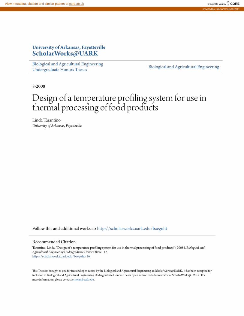
rated return air plenums. Thus, it can stand temperatures up to 1000°C (1832°F) and it has
low thermal conductivity (0.018 W m-1
°C-1) in comparison to common insulation blanket
like fiberglass (0.04 W m-1
°C-1).The core material of this insulation blanket is known as
Insulfrax ®, which is a combination of calcia, magnesia, and silica.
Figure 2: Insulation Blanket roll (left) and preliminary design with ceramic housing and insulation blanket (right)
Selection of insulation materials should be based on initial cost, effectiveness, durability,
and the adaptation of its form/shape. Materials should have a low thermal conductivity to reduce
the total coefficient of heat transmission (Carstens, 1993). Also, materials need to be rated as non-
flammable and specially non- toxic, since the device is to be exposed to food products. FyreWrap®
insulation blanket was chosen to prevent excessive increases in the internal temperature of the
device (See Figure 2). Two other techniques were studied for protecting the device from excessive
temperatures. First, the ceramic enclosure and the components inside were cooled in a refrigerator
before being tested in the oven. When it was found that this pre-cooling was not adequate to prevent
excessive temperatures in the enclosure during the tests, modifications were made so that a small
quantity of dry ice could be placed within the enclosure to assure a safe operating temperature for
the circuit components (<80°C).

9
4. Preliminary Design
4.1 Circuit blueprint
The circuit contains a thermocouple (type K), an AD595 chip, a 9-volt battery, and the EL-
USB3 for data acquisition. Figure 3 shows the diagram and the picture of the circuit set up. Notice
that pins 1, 4, 7, and 13 were grounded to the negative end of the 9-volt battery. The positive pole
of the 9-v source was connected to pin 11, and the thermocouple was connected to pins 1 and 14.
Pins 8 and 9 were directly connected to the positive input of the data logger. The negative input of
the data logger was connected to the negative pole of the battery as seen in Figure 3 (top). All of the
circuitry shown inside the rectangle that represents the chip is internal to the chip.
Figure 3: Sketch (top) and picture (bottom) of circuit blueprint
4.2 Further details of preliminary design: The housing for the device was chosen to be a ceramic
container (baking dish) of 3.5 in. of height, 8 in. wide and 8 in. long. The insulation chosen

10
consisted of FyreWrap® insulation blankets, which covered the circuit components. See Figure 4
for illustration of preliminary design.
Figure 4: Preliminary design.
The device was designed to transit through the oven, along with the product being cooked.
The goal was to avoid damaging the data-logger, which was the limiting component, by preventing
excessive high temperatures for at least 15 minutes. Therefore, the aim was to keep the data-logger
and the circuit components at or below their safe operating temperature (80°C).
To test the insulation, the ceramic container with some of the FyreWrap® was placed in a
conventional oven. A thermocouple was placed inside the insulation in the container so that
temperature within the insulation could be monitored for a period of 10 minutes. The thermocouple
was connected to a digital voltmeter through an AD595 chip (See Figure 5). The internal
temperature after 7 minutes remained at 65°C under an oven temperature of 200°C. Although the
temperature did not reach the maximum allowed (80°C), it was felt that improvement on the
insulation was needed to assure a safe operating temperature for the circuit components when
placed into the Stein oven, where higher heat transfer rates were expected.
Figure 5: Testing Insulation for Preliminary prototype.

11
5. Final Prototype.
The device is a data logging system designed to transit through a pilot-plant oven, along
with a product being thermally processed. A thermocouple connected to the data logger can then be
placed into the core of the product to be processed such that the user can obtain temperature
information for every moment of the cooking process. The temperature history recorded in the data
logger can then be downloaded and viewed with Windows software.
Insulation is an important part of the system, since it provides protection for the electronics
from the high temperatures used in food industry processing. The data logger itself is protected
from the extreme temperatures of the process by a secondary insulated ceramic container which
encloses the circuit components as well. This container has dimensions of 2 in. height, 4 in. long
and 4 in. wide. It also contains FyreWrap® layers covering the circuit components and the data
logger. This ceramic container was placed inside of the housing of the device (a ceramic baking
dish).
The housing of the final prototype was changed to a container of dimensions 3.25 in. of
height, 8 in. width and 8 in. long. The container was modified from its initial design due to the fact
that the original container did not comply with the size constraints of the project. In addition, layers
of FyreWrap® were placed between the circuit’s container and the housing of the device so that
heat transfer to the circuit components could be minimized.
Small pieces of dry ice were placed on top of the FyreWrap® insulation cloth in order to
keep cool the interior of the device for a longer period of time. Dry ice was used because of its low
temperature and direct sublimation to gas, which makes it a very effective coolant. It is a good
alternative since it does not cause damage to the circuits while being under high temperatures.
Finally, to minimize heat coming into the device, the lid of the container was sealed with
aluminum foil tape, an excellent vapor sealant that can withstand up to 500°F (Carstens, 1993).
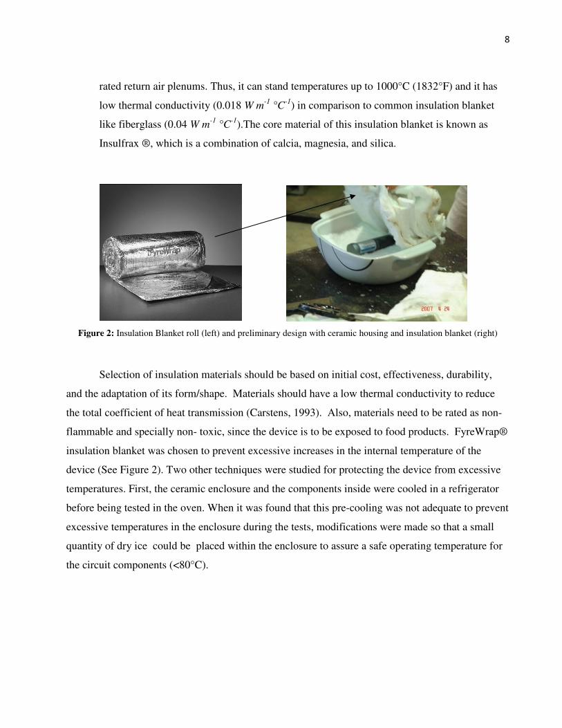
Figure 6 shows the inside of the device, as well as the prototype ready to go into the oven along
with the product. Notice in Figure 6 (middle) that dry ice was placed on top of a silicone sheet.
This silicone sheet prevents dry ice from getting into the circuits components as well as adding
extra insulation to the circuit.
12
Figure 6: Final Prototype
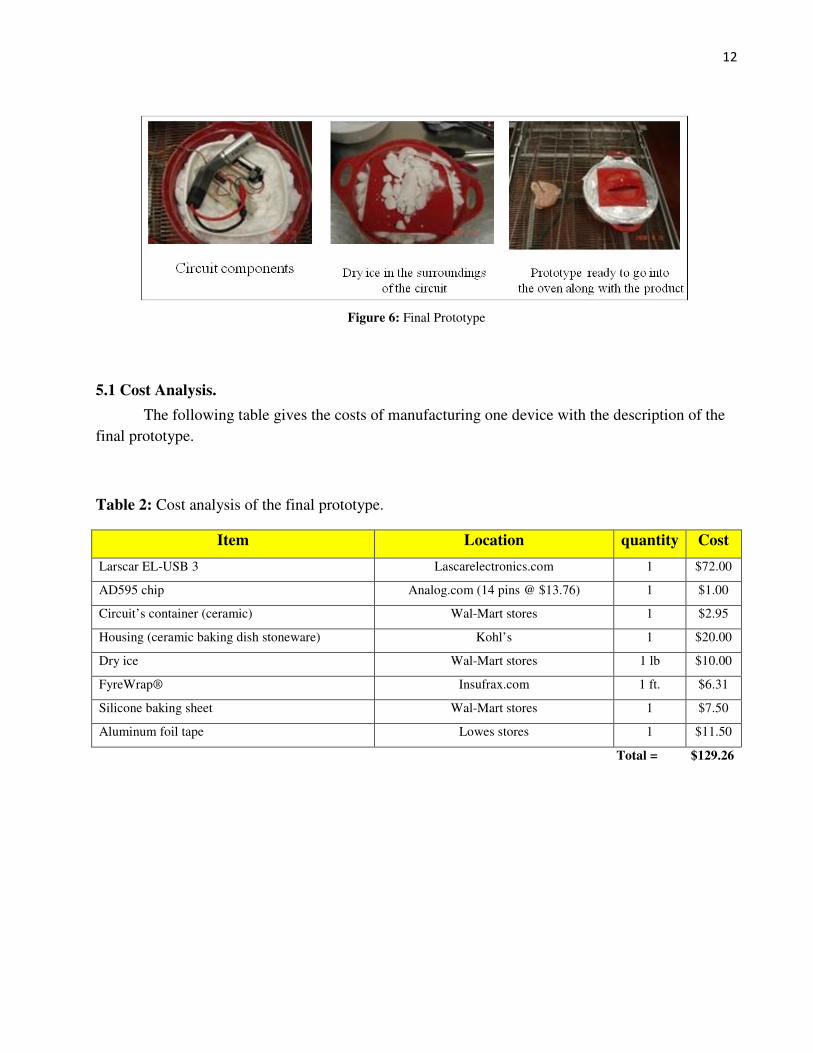
5.1 Cost Analysis.
The following table gives the costs of manufacturing one device with the description of the
final prototype.
Table 2: Cost analysis of the final prototype.
Item Location quantity Cost
Larscar EL-USB 3 Lascarelectronics.com 1 $72.00
AD595 chip Analog.com (14 pins @ $13.76) 1 $1.00
Circuit’s container (ceramic) Wal-Mart stores 1 $2.95
Housing (ceramic baking dish stoneware) Kohl’s 1 $20.00
Dry ice Wal-Mart stores 1 lb $10.00
FyreWrap® Insufrax.com 1 ft. $6.31
Silicone baking sheet Wal-Mart stores 1 $7.50
Aluminum foil tape Lowes stores 1 $11.50
Total = $129.26

13
6. Testing
6.1 Prototype testing
The device presented in this paper is a data logging system designed to transit through an
industrial oven, along with the product being thermally processed. The main goal of the design
process was to keep the internal temperature of the device cool enough that the circuit components
as well as the data logger are safe to operate for over 15 minutes under direct steam and air
impingement at a temperature of 400°F (204.4ºC).
To test the internal temperature of the device a thermocouple was initially inserted instead of
the circuit components. The pilot-scale air/steam impingement Stein oven (model 106) of the
poultry science department of the University of Arkansas was used for testing the device. The
device was placed on the conveyer belt of the oven and remained at 400°F for 15 min. The
thermocouple was connected to the IDL-800 digital voltmeter through an AD595 chip to monitor
the changes in temperature during the 15 minutes process. After the first 7 minutes the internal
temperature of the device remained between 20°C and 28°C (see Figure 7). This procedure was
repeated 5 times giving the same temperature range for the internal temperature of the device. Also,
the amount of dry ice included in the device was kept to 71/4 oz to get similar temperatures ranges
for each trial.
Figure 7: Initial testing. Stein oven at the pilot plant (left) and testing set up (right)

14
After testing the insulation, the data logging system was placed into the device. However,
the thermocouple length was shortened so that it could read the temperature of the surroundings of
the circuit components and the data logger. Then, the device was sealed with the aluminum foil
tape and placed on the conveyer belt of the oven and remained under steam/air impingement at
400°F for 13 minutes. The following graph shows the data saved on the data logger for this test.
Figure 8: Internal temperature of the device being tested under 205C in the Stein oven for over 13 minutes
This test procedure was performed 4 times (2 of these 4 tests were done for 15 minutes) so
that we could be sure that the internal temperature will remain at the same temperature range of 20-
28°C. Notice in figure 8 that temperature reading at time zero is 0°C (due to the dry ice). This is
still a safe operating temperature since the operating temperature range for the data logger and
circuit components was specified to be from -25°C to +80°C. The results shown in figure 8 were
very similar to the other trial runs, where it was observed that after 8 minutes of testing, the
temperature remained at 25-26°C. Consequently, it was proven that the device is able to withstand
the production and sanitation environments present in industrial thermal processing of food
products.
6.2 Bacteria testing.
Thermal Processing is a primary means of eliminating pathogens from meat products and
therefore serves to protect against foodborne disease. Ready to eat meat and poultry products can be
15
consumed without further cooking. Therefore, the presence of pathogens in these products could
present a food safety threat. Since 2002, hundreds of recalls have resulted in the loss of millions of
pounds of meat and poultry products as well as millions of dollars due to the concern of possible
contamination with foodborne pathogens (FSIS-USDA 2004). Among these pathogens is Listeria
monocytogenes.
L. monocytogenes, a gram-positive, non-spore forming, facultative, rod-shaped bacterium,
causes listerosis in young, old, pregnant and immunocompromised people with symptoms that
could lead to death (Bean and Griffin, 1990). The thermotolerance of L. monocytogenes is estimated
to be one of the highest among nonsporeformers (D’Sa et al., 2000).
In an effort to eliminate foodborne illness, the USDA has implemented a performance
standard that requires a reduction in the population of foodborne pathogens in certain fully cooked
and partially cooked poultry products equivalent to treating the product for a period of time equal to
7xD, where D is the decimal reduction time. The performance standard requires that the processor
provide the supporting information for the hazard analysis and decision-making documents
associated with the development of Hazard Analysis Critical Control Point (HACCP) plans, critical
limits, selection and frequency of monitoring, and verification procedures. The performance
standards aim at ensuring product safety and also giving establishments the flexibility to adopt
science-based processing procedures and controls (USDA-FSIS, 1999).
The objective of this study was to monitor the internal temperature of chicken breasts
contaminated with Listeria during air/steam impingement cooking as well as to determine the level
of pathogen destruction in the final product.
6.2-1 Material & Methods:
Although it would be advantageous to evaluate L. monocytogenes, it is generally undesirable
to risk working with this pathogen in a food-processing facility. Often, biological indicators are
used in challenge studies, because they are nonpathogenic and typically more heat-resistant than
pathogens, thus providing resistance information with a margin of safety (Fairchild and Foegeding,
1993). Therefore, L. innocua strain, a thermal resistance indicator for L. monocytogenes, was used
in this study.
16
6.2-2 Bacterial inoculation and product preparation:
Raw chicken breasts were obtained from a local grocery store and divided into three
different pieces of approximately 3oz of weight each. Each of the three chicken breasts
were initially inoculated with 0.3 mL of 109 cfu/mL of L. innocua; a non-pathogenic Listeria strain.
A pilot-scale air/steam impingement oven was used in this study to cook the chicken breast.
The oven air temperature was 204.4°C with an air circulation of 13 m3/min and moisture content of
60% (vol/vol) in the oven air.
Each chicken piece was placed on the conveyor belt. During cooking, a thermocouple
probe (type K) was placed at the center of each piece. The temperature was monitored every 10
seconds by using the prototype. Each sample was then cooked until its core temperature reached
165 °F (12 minutes approximately cooking time per piece). After cooking, the chicken breasts were
cooled at ambient temperature (25°C).
6.2-3 Bacterial enumeration:
After each chicken breast was cooked, it was placed in a sterile bag and 0.9 mL of phosphate
buffer saline solution (pH 7.0) was then added to each bag. Chicken breast pieces were labeled as
sample A, B, and C, respectively. Each sample was rubbed with the solution for two minutes, to
ensure that the buffer solution and chicken juices were evenly distributed. Next, serial dilution
techniques were used to inoculate Petri dishes with varying dilutions of liquid extracted from each
chicken bag. The petri dishes used contained MOX (modified oxford medium) which is selective
for Listeria innocua. For each sample, three Petri plates at 10-1 dilution and two Petri plates of 10-2,
10-3, and 10-4 dilution were incubated for 48 hours at a temperature of 37 °C. In addition to the
Petri plates, a sheet of Petri film was inoculated per each sample at a dilution of 10-2 and incubated
for 48 hours at 37 degrees °C.

17
7. Results & Discussion.
The MOX plates were observed for signs of contamination. After 48 hours of incubation it
was observed that there were no signs of Listeria growth, even at the -1 dilution. This was true for
all three chicken breasts samples. In addition, the data acquired from the data-logger provided the
internal temperature of the chicken samples during the entire cooking process. Notice in figure 10
that after 12.4 minutes of cooking, the internal temperature at the core of the chicken sample
reached 74°C(165.2°F), which satisfy the USDA guideline of at least 165°F internal temperature for
poultry products (USDA-FSIS, 2006).
Figure 10 shows that there is a peak in the curve before the end point where the product is
out of the oven. At this peak, the acquired data shows that after 10.2 minutes of cooking time, the
internal temperature at the core reached 80°C (176°F). Without using the device presented in this
work, it could not have been possible to measure the internal temperature of the chicken breast
sample.
Figure 9: Thermal processing of contaminated chicken breast (sample A)
It is important to mention that it took the product 23 seconds to reach the point where it
received the steam for cooking, and it took the same amount of time for the product to reach the
point where food processor will insert the probe to measure the internal temperature of the cooked
product. Therefore, the temperature values measured by the food processor would be lower than the
actual temperature of the product at the point of removal from its cooking medium.

18
Figure 10 shows how the internal temperature at the core of food products is currently
measured during thermal process. This is done once the product is out of the oven where the
technician inserts a probe into the core of the product making sure the temperature reads at least
73.5°C (165°F).
Figure 9: Cooked product being measured as soon as it has left the oven.
The temperature measurements done by the technician were compared with the data saved
by the data logger of the device. Notice in Table 3 that the divergence in values is due to the
difference in sensitivity of the device and the one used by the technician. However, these results
proved that the device was capable of record accurate readings for the entire thermal process of the
chicken breast samples.
Table 3: Comparison of temperature measurements of the chicken breast samples taken at the end
of their cooking process.
Sample Technician (temperature, °C) Device (temperature, °C)
A 73.8 74
B 75.5 76
C 74.6 75

19
8. Conclusions.
The device presented in this paper offers a reliable method of measuring the true product
temperature during its entire thermal processing. It also allows users to utilize the acquired
information into process optimization. Testing of the prototype showed that the device is able to
withstand harsh environment conditions and that it is able to provide accurate data of the cooking
process. It represents a great advantage for food industries since it is a simple way of providing full
process validation documentation to satisfy government requirements and customer necessities for
safer food products.
Current performance standards require processors to validate the efficiency of their thermal
processes to reduce microbial contamination. This device not only provides the entire temperature
profile of the cooking process, but also provides the information needed for determining process
lethality. The USDA-FSIS issued guidelines to the fact that cooked poultry products should reach
an internal temperature of at least 165°F before being removed from the cooking medium (USDA-
FSIS, 2006). Currently this is achieved by inserting a probe at the core of the product when it is out
of the oven. However, it takes few seconds for the product to leave the oven where it loses heat.
By using the developed device, food processors would be able to obtain real measurements for their
processes and provide proof that the core temperature of the product has reached the USDA-FSIS
guidelines before it cools. Other advantages of using the proposed device include the ability to
identify problems in the process before affecting the quality of the product, increase productivity,
minimize fuel consumption, and control product quality.
8.1 Some suggestions for further work.
• Test the device at temperatures above 400°F and for periods longer than 15 minutes to
determine maximum operating points of the device.
• Find an alternative for the dry ice. Dry ice requires special handling that may cause some
delay on industrial processing.
• Include other applications on the device like being able to measure product’s water content,
or monitor different products at the same time.

20
9. Acknowledgments.
I would like to acknowledge my advisor Dr. Carl Griffis for the guidance and support
throughout this work. I would also like to thank Dr. Betty Martin and Erin Shannon for their
valuable help and support.
Sincere thanks are extended to Rodney Wolfe and Tom Harrison for their help in the
processing plant. I also would like to express my sincere appreciation and gratitude to Dr. Julie
Carrier and Dr. Bajwa for reviewing this thesis.

21
10. References
Bean, N.H., and P. M. Griffin. (1990). Foodborne disease outbreaks in the United States, 1973-
1977: Pathogens, vehicles, and trends. Journal of Food Protection, 53:804-817.
Carstens, J.R. (1993). Electrical Sensors and Transducers. New Jersey: Regents/Prentice Hall.
Center of Disease Control. (2000). Surveillance for foodborne disease outbreaks- United States
1993-1997. http://www.cdc.gov/epo/mmwr/preview/mmwrhtml/ss4901a1.htm
Doyle, M.E. and A.S. Mazzotta. (2000). Review of studies on the thermal resistance of Salmonella.
Journal of Food Protection, 63:779-795.
D’Sa, E.M., M.A. Harrison, S.E. Williams, and M.H. Broccoli. (2000). Effectiveness of two
cooking systems in destroying Escherichia coli O157:H7 and Listeria monocytogenes in
ground beef patties. Journal of Food Protection, 63:894-899.
Fairchild, T.M., and P.M. Foegeding. (1993). A proposed nonpathogenic biological indicator for
thermal inactivation of Listeria monocytogenes. Applied and Environmental Microbiology,
59:1247–1250.
Ma, L. and Y. Tao. (2005). An infrared and laser range imaging system for real-time estimation of
internal temperature in chicken breast after cooking. ASAE, 48(2):9.
Murphy, R.Y., L. K. Duncan, M. E. Berrang, J. A. Marcy, A. and R. E. Wolfe. (2002). Thermal
inactivation D- and Z- values of Salmonella and Listeria innocua in fully cooked and
vacuum packaged chicken breast meat during post-cook heat treatment. Journal of Food
Science, 81:1578-1583.
Murphy, R. Y., T. Osaili, L.K. Duncan, and J.A. Marcy. (2004). Thermal Inactivation of Salmonella
and Listeria monocytogenes in ground chicken thigh/leg meat and skin. Journal of Poultry
Science, 83: 1218-1225.

22
Richardson, P. (2004). Improving the thermal processing of foods. Cambridge : Woodhead
Publishers.75-89.
USDA-FSIS. (1999). Performance standards for the production of certain meat and poultry
products. Government Printing Office, Washington, DC. Federal Regulations, 64:732–749.
USDA-FSIS. (2001). Recall notification report. http://www.fsis.usda.gov/OA/recalls/rnrfiles/
rnr076-2000.htm. Accessed May 25, 2008.
USDA-FSIS. (2004). Recall notification report. http://www.fsis.usda.gov/OA/recalls/rec_intr.htm
USDA-FSIS. (2006). Single minimum internal temperature established for cooked poultry.
http://www.fsis.usda.gov/News/NR_040506_01/index.asp. Accessed 2 June 2008.