Embed Size (px)
Citation preview
Open Journal of Fluid Dynamics, 2017, 7, 410-425 http://www.scirp.org/journal/ojfd
ISSN Online: 2165-3860 ISSN Print: 2165-3852
DOI: 10.4236/ojfd.2017.73028 Sep. 28, 2017 410 Open Journal of Fluid Dynamics
Design of a Three-Dimensional Centrifugal Fan with Controlled Blade Loading Approach
Jin Xiong, Xin Ai, Kaibin Wang, Jingyin Li*
School of Energy and Power Engineering, Xi’an Jiaotong University, Xi’an, China
Abstract The high flow-rate centrifugal fan needs a three-dimensional impeller to achieve a high efficiency. In this paper, the design procedure of a high-efficiency three-dimensional centrifugal fan is presented. First, the main dimensions of the fan were calculated by using the conventional one-dimensional method. Then, the blade loading or the angular momentum distribution along the meridional streamline on the blade surfaces is prescribed. After that, the three-dimensional blade is determined by using the streamline curvature method. With the aid of numerical simulations, the performance of the three-dimensional fan was im-proved and some of the key influence factors were investigated. The analyses indicate that, as to the high flow-rate centrifugal fan, the Stanitz modified for-mula is recommended to calculate the separation radius, rb. A proper increase in the separation radius is beneficial for the fan’s performance. It is also indicated that a decrease in the angular momentum on the hub leads to an increase in to-tal pressure efficiency, under the condition of a given constant mean angular momentum at the outlet of the blade. In addition, the installation of a fairing on the hub plate can improve the fan’s efficiency evidently when the streamline curvature method is adopted to design the three-dimensional impeller.
Keywords Centrifugal Fan, Controlled Angular Momentum, High Flow-Rate
1. Introduction
Centrifugal machinery has been widely used in different fields. The impeller, as a key component, has a significant effect on the performance of the centrifugal machinery. Because of the high energy consumption and the high manufactur-ing cost, improving the aerodynamic performance of the centrifugal compressor impeller has always been the hot research topic in the literature. Some examples
How to cite this paper: Xiong, J., Ai, X., Wang, K.B. and Li, J.Y. (2017) Design of a Three-Dimensional Centrifugal Fan with Controlled Blade Loading Approach. Open Journal of Fluid Dynamics, 7, 410-425. https://doi.org/10.4236/ojfd.2017.73028 Received: August 14, 2017 Accepted: September 25, 2017 Published: September 28, 2017 Copyright © 2017 by authors and Scientific Research Publishing Inc. This work is licensed under the Creative Commons Attribution International License (CC BY 4.0). http://creativecommons.org/licenses/by/4.0/
Open Access
J. Xiong et al.
DOI: 10.4236/ojfd.2017.73028 411 Open Journal of Fluid Dynamics
are cited here as references. For instance, Kim et al. [1] optimized the meridional flow path of the impeller in terms of Pareto-optimal solutions. The optimization results showed that both of the isentropic efficiency and the total pressure ratio were enhanced at the design and off-design conditions. In another paper, Kim et al. [2] optimized the meridional channel of impeller based on the radial basis neural network method, to improve the pressure ratio. The results showed that the pressure ratio of the optimum impeller at the design flow coefficient was en-hanced by 2.43% in comparison with the reference impeller, and the pressure ra-tios at the off-design flow coefficients were also improved. In the research of Shibata et al. [3], five types of unshrouded impellers were designed, manufac-tured, and tested to evaluate the effects of blade loading, back sweep angle, and relative velocity diffusion ratio on the compressor performance. It was con-cluded that an increased relative velocity diffusion ratio coupled with large back sweep angles was a very effective way to improve the compressor stage efficien-cy. An appropriate blade loading distribution was a key factor in achieving a wide operating range as well as high efficiency. In their later study [4], the blade loading distribution was further optimized, with four shrouded impellers being designed, manufactured and tested, to evaluate the effects of blade loading, back sweep angle, and relative velocity diffusion ratio on compressor performance. It was concluded that aft-loading coupled with a high degree of reaction was a very effective way to improve surge margin as well as stage efficiency. In the aerody-namic design of a centrifugal impeller with the pressure ratio up to 6.2, Zange-neh et al. [5] found that the choice of a strongly aft-loaded hub and mildly aft-loaded shroud for the main blade helped to provide good compromise be-tween suppression of secondary flows and decreasing the shock losses in the in-ducer. Furthermore, by unloading the hub and mid-span rapidly in the inducer area, it was possible to reduce the shock strength in the inducer from mid-span to hub. The conclusions of Xi et al. [6] and Geng et al. [7] also indicated that the angular momentum distribution along impeller surface has a great influence on the performance of centrifugal impellers. At present, investigations and explora-tions into the aerodynamics of the centrifugal compressor impeller almost cover its every aspect, and the impeller with three-dimensional (3D) blades has been adopted in practice for decades.
Compared with the vast papers published on centrifugal compressor impel-lers, only a few documents were devoted to the aerodynamic design and optimi-zation of the impeller of centrifugal fans, with less being focused on the 3D im-peller. The major reason is that the centrifugal fan’s impeller is generally manu-factured by welding steel plates. Therefore, it is hard to make the meridional flow path as smooth as those of centrifugal compressors [1] and pumps [8], and the channel has to take the simple shape as that shown in Figure 2 in reference [9]. In addition, because the diameter of a large centrifugal fan’s impeller can be up to 3 - 4 meters, its blades are generally two-dimensional (not twisted blades) [10] [11] in order to reduce manufacturing costs. This tradition even affects the design of the impeller in small centrifugal fans [12] and the impeller using air-
J. Xiong et al.
DOI: 10.4236/ojfd.2017.73028 412 Open Journal of Fluid Dynamics
foil-shaped blades [13]. The centrifugal fan has the features of a high flow rate and a large relative
width of the impeller. This implies that the 3D impeller is more suitable to be adopted to face the complex internal flow fields in the centrifugal fan, which at-tracted the attention of some researchers. For example, in 2007 Tsai and Wu [14] designed a miniature 3D centrifugal fan’s impeller by just modeling a com-pressor prototype which has a high pressure ratio. They matched the impeller with a volute and manufactured the 3D impeller by CNC 5-axex machines. Un-fortunately, the experimental measurements showed that at the same low rota-tional speed of 2000 rpm, both of the flow rate and pressure rise of the 3D fan were less than the commercial fan in the market, and the designed fan was rather inefficient either. In the study of Lee et al. [15], they designed a 3D impeller by adding an inducer to the 2D blades, which is a common practice in the design of 3D compressor impeller in the 1970s. But the efficiency of this centrifugal fan is only 70%. Kruyt and Westra [16] designed the 3D blades of centrifugal pumps and fans by changing the stacking condition at the trailing edge in combination with the prescribed mean-swirl distribution along the blade. By altering a para-meter called “q”, the blades loads can be changed from the front-loading to the aft-loading.
From the discussion above, the application of the 3D impeller in centrifugal fans is rather limited till now compared with compressors, due to the manufac-turing cost and the simple shape of the meridional flow path. Different ap-proaches in the design of the 3D impeller in centrifugal fan have been investi-gated by researchers, but the efficiencies are not as high as expected. With the great progress in manufacturing technology like 3D printing in recent time, 3D impellers in centrifugal fans have found more applications, especially for those in mass production. This is because the manufacturing cost of the mass-production 3D impeller in centrifugal fans can drop considerably by virtue of comprehensive flow field analyses and performance tests by using the cheap models made by 3D printing technology.
This paper is dedicated to exploring a reliable method on the design of a high-efficiency 3D centrifugal fan. In this paper, the aerodynamic load of the angular momentum (rVθ) along the blade surface is controlled by proposed piecewise polynomials. Then the 3D blade is determined by using the streamline curvature method. After that, the flow field and aerodynamic performance of the 3D fan are simulated and analyzed, to determine the best design, with the volute and air inlet being designed in the conventional way. Finally, the high efficiency 3D centrifugal fan is made and tested.
2. Theory and Methods 2.1. Distribution Law of Angular Momentum
The distribution law of angular momentum on the blade surface is prescribed by three polynomials. The partition of the blade meridional channel is schematical-
J. Xiong et al.
DOI: 10.4236/ojfd.2017.73028 413 Open Journal of Fluid Dynamics
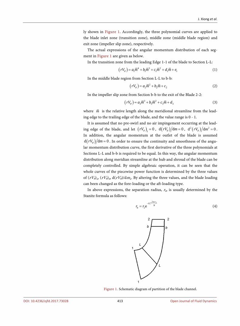
ly shown in Figure 1. Accordingly, the three polynomial curves are applied to the blade inlet zone (transition zone), middle zone (middle blade region) and exit zone (impeller slip zone), respectively.
The actual expressions of the angular momentum distribution of each seg-ment in Figure 1 are given as below.
In the transition zone from the leading Edge 1-1 of the blade to Section L-L:
( ) 4 3 21 1 1 1 1rV a m b m c m d m eθ = + + + + (1)
In the middle blade region from Section L-L to b-b:
( ) 22 2 2rV a m b m cθ = + + (2)
In the impeller slip zone from Section b-b to the exit of the Blade 2-2:
( ) 3 23 3 3 3rV a m b m c m dθ = + + + (3)
where m is the relative length along the meridional streamline from the lead-ing edge to the trailing edge of the blade, and the value range is 0 - 1.
It is assumed that no pre-swirl and no air impingement occurring at the lead-ing edge of the blade, and let ( )1 0rVθ = , ( )d d 0rV mθ = , ( )2 2d d 0rV mθ = . In addition, the angular momentum at the outlet of the blade is assumed ( )d d 0rV mθ = . In order to ensure the continuity and smoothness of the angu-
lar momentum distribution curve, the first derivative of the three polynomials at Sections L-L and b-b is required to be equal. In this way, the angular momentum distribution along meridian streamline at the hub and shroud of the blade can be completely controlled. By simple algebraic operation, it can be seen that the whole curves of the piecewise power function is determined by the three values of (rVθ)L, (rVθ)b, d(rVθ)/dmL. By altering the three values, and the blade loading can been changed as the fore-loading or the aft-loading type.
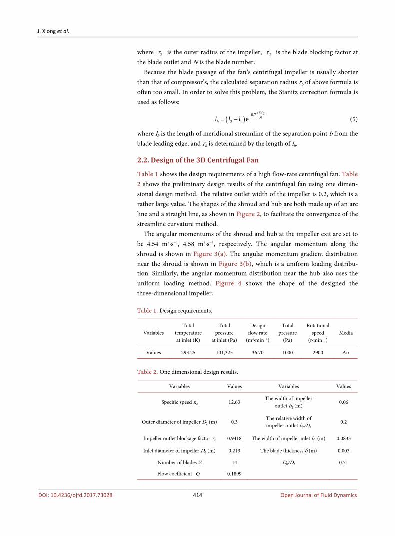
In above expressions, the separation radius, rb, is usually determined by the Stanitz formula as follows:
22π0.7
2e Nbr r
τ−
= (4)
Figure 1. Schematic diagram of partition of the blade channel.
J. Xiong et al.
DOI: 10.4236/ojfd.2017.73028 414 Open Journal of Fluid Dynamics
where 2r is the outer radius of the impeller, 2τ is the blade blocking factor at the blade outlet and N is the blade number.
Because the blade passage of the fan’s centrifugal impeller is usually shorter than that of compressor’s, the calculated separation radius rb of above formula is often too small. In order to solve this problem, the Stanitz correction formula is used as follows:
( )22π0.7
2 1 e Nbl l l
τ−
= − (5)
where lb is the length of meridional streamline of the separation point b from the blade leading edge, and rb is determined by the length of lb.
2.2. Design of the 3D Centrifugal Fan
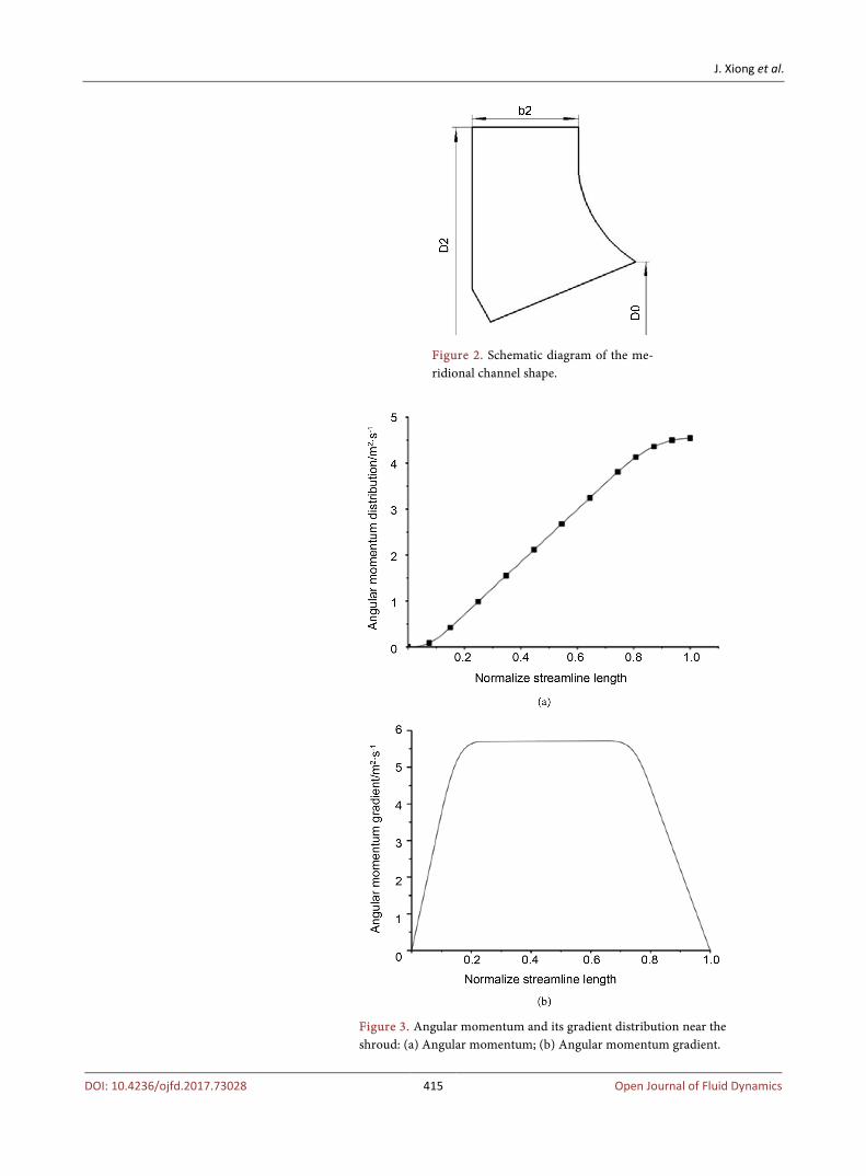
Table 1 shows the design requirements of a high flow-rate centrifugal fan. Table 2 shows the preliminary design results of the centrifugal fan using one dimen-sional design method. The relative outlet width of the impeller is 0.2, which is a rather large value. The shapes of the shroud and hub are both made up of an arc line and a straight line, as shown in Figure 2, to facilitate the convergence of the streamline curvature method.
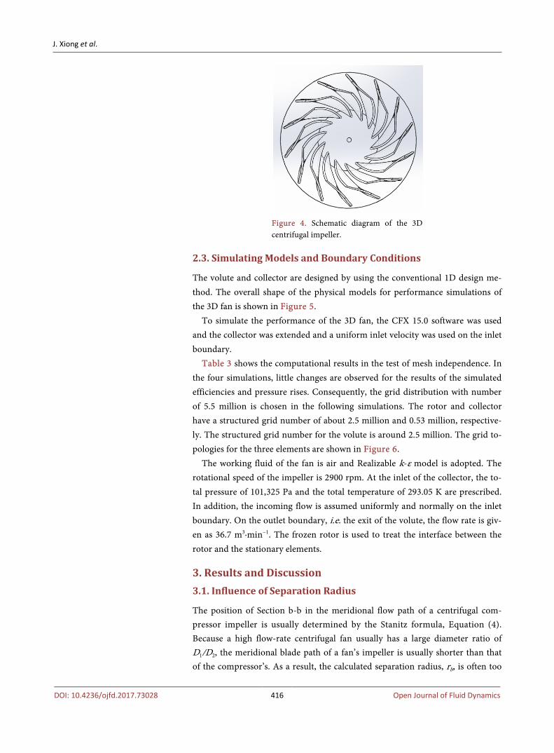
The angular momentums of the shroud and hub at the impeller exit are set to be 4.54 m2·s−1, 4.58 m2·s−1, respectively. The angular momentum along the shroud is shown in Figure 3(a). The angular momentum gradient distribution near the shroud is shown in Figure 3(b), which is a uniform loading distribu-tion. Similarly, the angular momentum distribution near the hub also uses the uniform loading method. Figure 4 shows the shape of the designed the three-dimensional impeller. Table 1. Design requirements.
Variables Total
temperature at inlet (K)
Total pressure
at inlet (Pa)
Design flow rate
(m3·min−1)
Total pressure
(Pa)
Rotational speed
(r·min−1) Media
Values 293.25 101,325 36.70 1000 2900 Air
Table 2. One dimensional design results.
Variables Values Variables Values
Specific speed ns 12.63 The width of impeller
outlet b2 (m) 0.06
Outer diameter of impeller D2 (m) 0.3 The relative width of impeller outlet b2/D2
0.2
Impeller outlet blockage factor τ2 0.9418 The width of impeller inlet b1 (m) 0.0833
Inlet diameter of impeller D0 (m) 0.213 The blade thickness δ (m) 0.003
Number of blades Z 14 D0/D2 0.71
Flow coefficient Q 0.1899
J. Xiong et al.
DOI: 10.4236/ojfd.2017.73028 415 Open Journal of Fluid Dynamics
Figure 2. Schematic diagram of the me-ridional channel shape.
Figure 3. Angular momentum and its gradient distribution near the shroud: (a) Angular momentum; (b) Angular momentum gradient.
J. Xiong et al.
DOI: 10.4236/ojfd.2017.73028 416 Open Journal of Fluid Dynamics
Figure 4. Schematic diagram of the 3D centrifugal impeller.
2.3. Simulating Models and Boundary Conditions
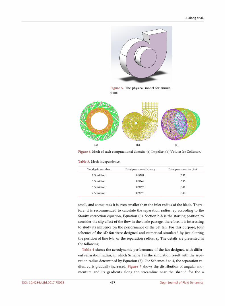
The volute and collector are designed by using the conventional 1D design me-thod. The overall shape of the physical models for performance simulations of the 3D fan is shown in Figure 5.
To simulate the performance of the 3D fan, the CFX 15.0 software was used and the collector was extended and a uniform inlet velocity was used on the inlet boundary.
Table 3 shows the computational results in the test of mesh independence. In the four simulations, little changes are observed for the results of the simulated efficiencies and pressure rises. Consequently, the grid distribution with number of 5.5 million is chosen in the following simulations. The rotor and collector have a structured grid number of about 2.5 million and 0.53 million, respective-ly. The structured grid number for the volute is around 2.5 million. The grid to-pologies for the three elements are shown in Figure 6.
The working fluid of the fan is air and Realizable k-ε model is adopted. The rotational speed of the impeller is 2900 rpm. At the inlet of the collector, the to-tal pressure of 101,325 Pa and the total temperature of 293.05 K are prescribed. In addition, the incoming flow is assumed uniformly and normally on the inlet boundary. On the outlet boundary, i.e. the exit of the volute, the flow rate is giv-en as 36.7 m3·min−1. The frozen rotor is used to treat the interface between the rotor and the stationary elements.
3. Results and Discussion 3.1. Influence of Separation Radius
The position of Section b-b in the meridional flow path of a centrifugal com-pressor impeller is usually determined by the Stanitz formula, Equation (4). Because a high flow-rate centrifugal fan usually has a large diameter ratio of D1/D2, the meridional blade path of a fan’s impeller is usually shorter than that of the compressor’s. As a result, the calculated separation radius, rb, is often too
J. Xiong et al.
DOI: 10.4236/ojfd.2017.73028 417 Open Journal of Fluid Dynamics
Figure 5. The physical model for simula-tions.
(a) (b) (c)
Figure 6. Mesh of each computational domain: (a) Impeller; (b) Volute; (c) Collector. Table 3. Mesh independence.
Total grid number Total pressure efficiency Total pressure rise (Pa)
1.5 million 0.9281 1352
3.5 million 0.9268 1335
5.5 million 0.9276 1341
7.5 million 0.9275 1340
small, and sometimes it is even smaller than the inlet radius of the blade. There-fore, it is recommended to calculate the separation radius, rb, according to the Stanitz correction equation, Equation (5). Section b-b is the starting position to consider the slip effect of the flow in the blade passage; therefore, it is interesting to study its influence on the performance of the 3D fan. For this purpose, four schemes of the 3D fan were designed and numerical simulated by just altering the position of line b-b, or the separation radius, rb. The details are presented in the following.
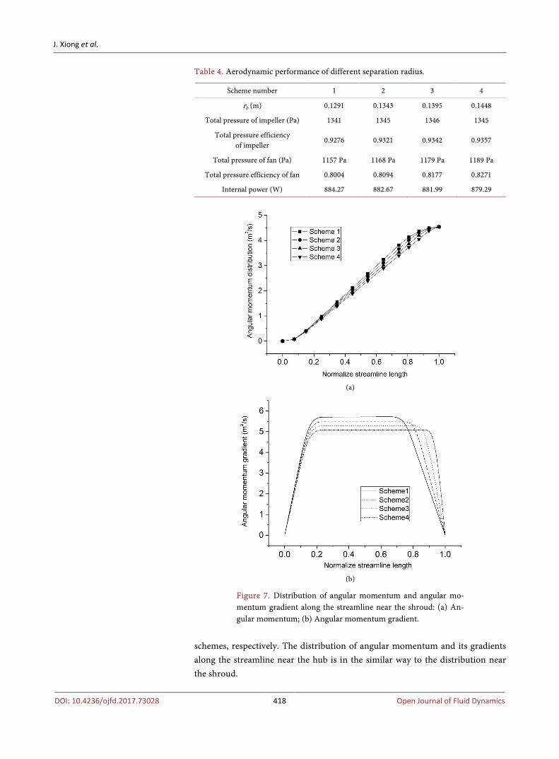
Table 4 shows the aerodynamic performance of the fan designed with differ-ent separation radius, in which Scheme 1 is the simulation result with the sepa-ration radius determined by Equation (5). For Schemes 2 to 4, the separation ra-dius, rb, is gradually increased. Figure 7 shows the distribution of angular mo-mentum and its gradients along the streamline near the shroud for the 4
J. Xiong et al.
DOI: 10.4236/ojfd.2017.73028 418 Open Journal of Fluid Dynamics
Table 4. Aerodynamic performance of different separation radius.
Scheme number 1 2 3 4
rb (m) 0.1291 0.1343 0.1395 0.1448
Total pressure of impeller (Pa) 1341 1345 1346 1345
Total pressure efficiency of impeller
0.9276 0.9321 0.9342 0.9357
Total pressure of fan (Pa) 1157 Pa 1168 Pa 1179 Pa 1189 Pa
Total pressure efficiency of fan 0.8004 0.8094 0.8177 0.8271
Internal power (W) 884.27 882.67 881.99 879.29
(a)
(b)
Figure 7. Distribution of angular momentum and angular mo-mentum gradient along the streamline near the shroud: (a) An-gular momentum; (b) Angular momentum gradient.
schemes, respectively. The distribution of angular momentum and its gradients along the streamline near the hub is in the similar way to the distribution near the shroud.
J. Xiong et al.
DOI: 10.4236/ojfd.2017.73028 419 Open Journal of Fluid Dynamics
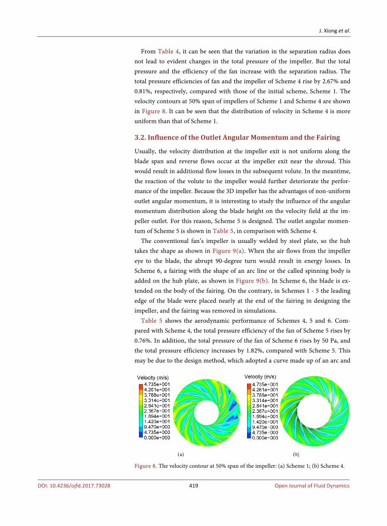
From Table 4, it can be seen that the variation in the separation radius does not lead to evident changes in the total pressure of the impeller. But the total pressure and the efficiency of the fan increase with the separation radius. The total pressure efficiencies of fan and the impeller of Scheme 4 rise by 2.67% and 0.81%, respectively, compared with those of the initial scheme, Scheme 1. The velocity contours at 50% span of impellers of Scheme 1 and Scheme 4 are shown in Figure 8. It can be seen that the distribution of velocity in Scheme 4 is more uniform than that of Scheme 1.
3.2. Influence of the Outlet Angular Momentum and the Fairing
Usually, the velocity distribution at the impeller exit is not uniform along the blade span and reverse flows occur at the impeller exit near the shroud. This would result in additional flow losses in the subsequent volute. In the meantime, the reaction of the volute to the impeller would further deteriorate the perfor-mance of the impeller. Because the 3D impeller has the advantages of non-uniform outlet angular momentum, it is interesting to study the influence of the angular momentum distribution along the blade height on the velocity field at the im-peller outlet. For this reason, Scheme 5 is designed. The outlet angular momen-tum of Scheme 5 is shown in Table 5, in comparison with Scheme 4.
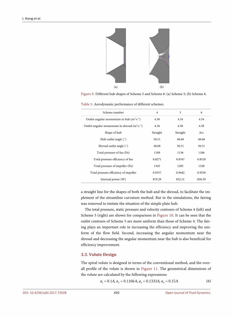
The conventional fan’s impeller is usually welded by steel plate, so the hub takes the shape as shown in Figure 9(a). When the air flows from the impeller eye to the blade, the abrupt 90-degree turn would result in energy losses. In Scheme 6, a fairing with the shape of an arc line or the called spinning body is added on the hub plate, as shown in Figure 9(b). In Scheme 6, the blade is ex-tended on the body of the fairing. On the contrary, in Schemes 1 - 5 the leading edge of the blade were placed nearly at the end of the fairing in designing the impeller, and the fairing was removed in simulations.
Table 5 shows the aerodynamic performance of Schemes 4, 5 and 6. Com-pared with Scheme 4, the total pressure efficiency of the fan of Scheme 5 rises by 0.76%. In addition, the total pressure of the fan of Scheme 6 rises by 50 Pa, and the total pressure efficiency increases by 1.82%, compared with Scheme 5. This may be due to the design method, which adopted a curve made up of an arc and
Figure 8. The velocity contour at 50% span of the impeller: (a) Scheme 1; (b) Scheme 4.
J. Xiong et al.
DOI: 10.4236/ojfd.2017.73028 420 Open Journal of Fluid Dynamics
(a) (b)
Figure 9. Different hub shapes of Scheme 5 and Scheme 6: (a) Scheme 5; (b) Scheme 6. Table 5. Aerodynamic performance of different schemes.
Scheme number 4 5 6
Outlet angular momentum in hub (m2·s−1) 4.58 4.54 4.54
Outlet angular momentum in shroud (m2∙s−1) 4.54 4.58 4.58
Shape of hub Straight Straight Arc
Hub outlet angle (˚) 50.51 48.68 48.68
Shroud outlet angle (˚) 48.68 50.51 50.51
Total pressure of fan (Pa) 1189 1136 1186
Total pressure efficiency of fan 0.8271 0.8347 0.8529
Total pressure of impeller (Pa) 1345 1285 1328
Total pressure efficiency of impeller 0.9357 0.9442 0.9550
Internal power (W) 879.29 832.51 850.59
a straight line for the shapes of both the hub and the shroud, to facilitate the im-plement of the streamline curvature method. But in the simulations, the fairing was removed to imitate the situation of the simple plate hub.
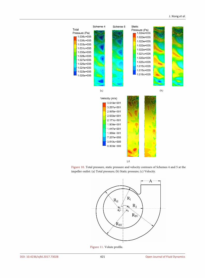
The total pressure, static pressure and velocity contours of Scheme 4 (left) and Scheme 5 (right) are shown for comparison in Figure 10. It can be seen that the outlet contours of Scheme 5 are more uniform than those of Scheme 4. The fair-ing plays an important role in increasing the efficiency and improving the uni-form of the flow field. Second, increasing the angular momentum near the shroud and decreasing the angular momentum near the hub is also beneficial for efficiency improvement.
3.3. Volute Design
The spiral volute is designed in terms of the conventional method, and the over-all profile of the volute is shown in Figure 11. The geometrical dimensions of the volute are calculated by the following expressions:
1 2 3 40.1 , 0.1166 , 0.1333 , 0.15a A a A a A a A= = = = (6)
J. Xiong et al.
DOI: 10.4236/ojfd.2017.73028 421 Open Journal of Fluid Dynamics
Figure 10. Total pressure, static pressure and velocity contours of Schemes 4 and 5 at the impeller outlet: (a) Total pressure; (b) Static pressure; (c) Velocity.
Figure 11. Volute profile.
J. Xiong et al.
DOI: 10.4236/ojfd.2017.73028 422 Open Journal of Fluid Dynamics
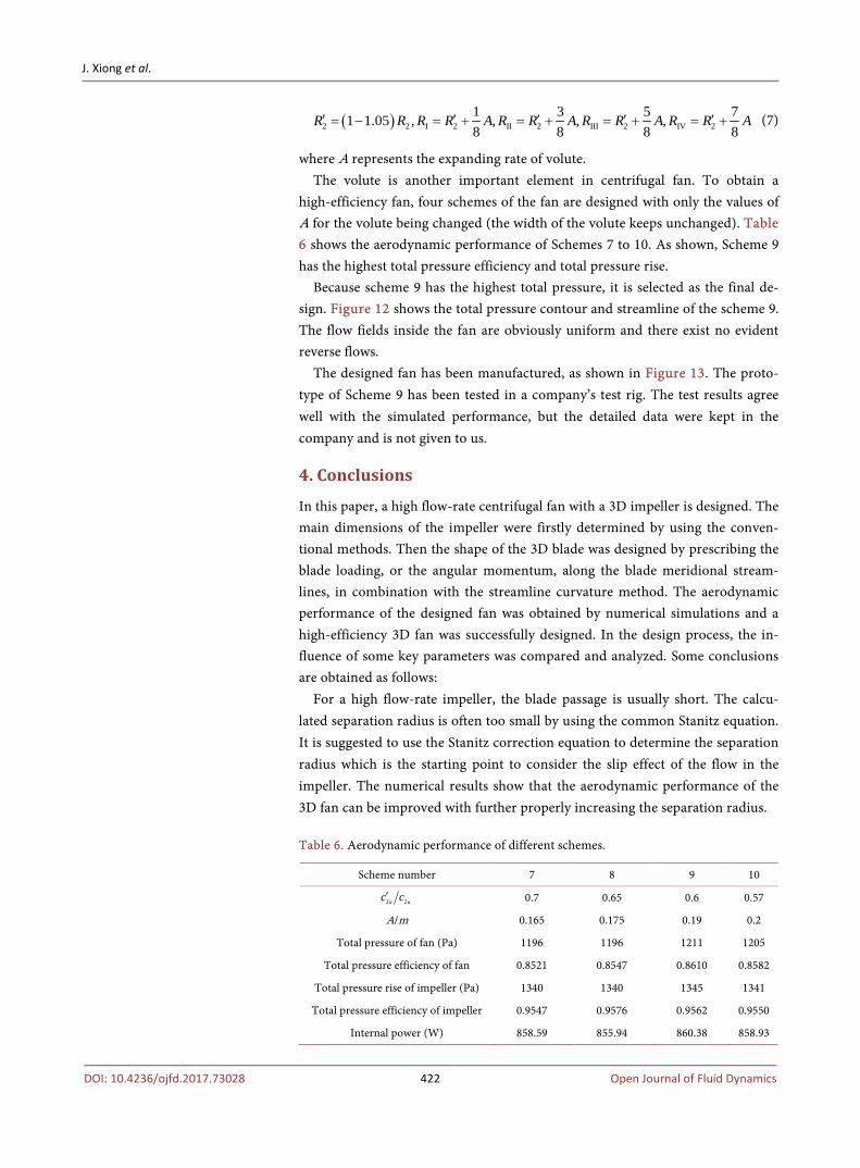
( )2 2 I 2 II 2 III 2 IV 21 3 5 71 1.05 , , , ,8 8 8 8
R R R R A R R A R R A R R A′ ′ ′ ′ ′= − = + = + = + = + (7)
where A represents the expanding rate of volute. The volute is another important element in centrifugal fan. To obtain a
high-efficiency fan, four schemes of the fan are designed with only the values of A for the volute being changed (the width of the volute keeps unchanged). Table 6 shows the aerodynamic performance of Schemes 7 to 10. As shown, Scheme 9 has the highest total pressure efficiency and total pressure rise.
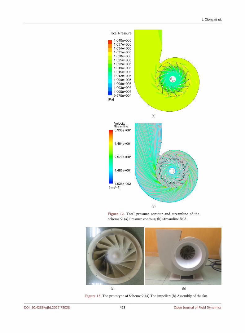
Because scheme 9 has the highest total pressure, it is selected as the final de-sign. Figure 12 shows the total pressure contour and streamline of the scheme 9. The flow fields inside the fan are obviously uniform and there exist no evident reverse flows.
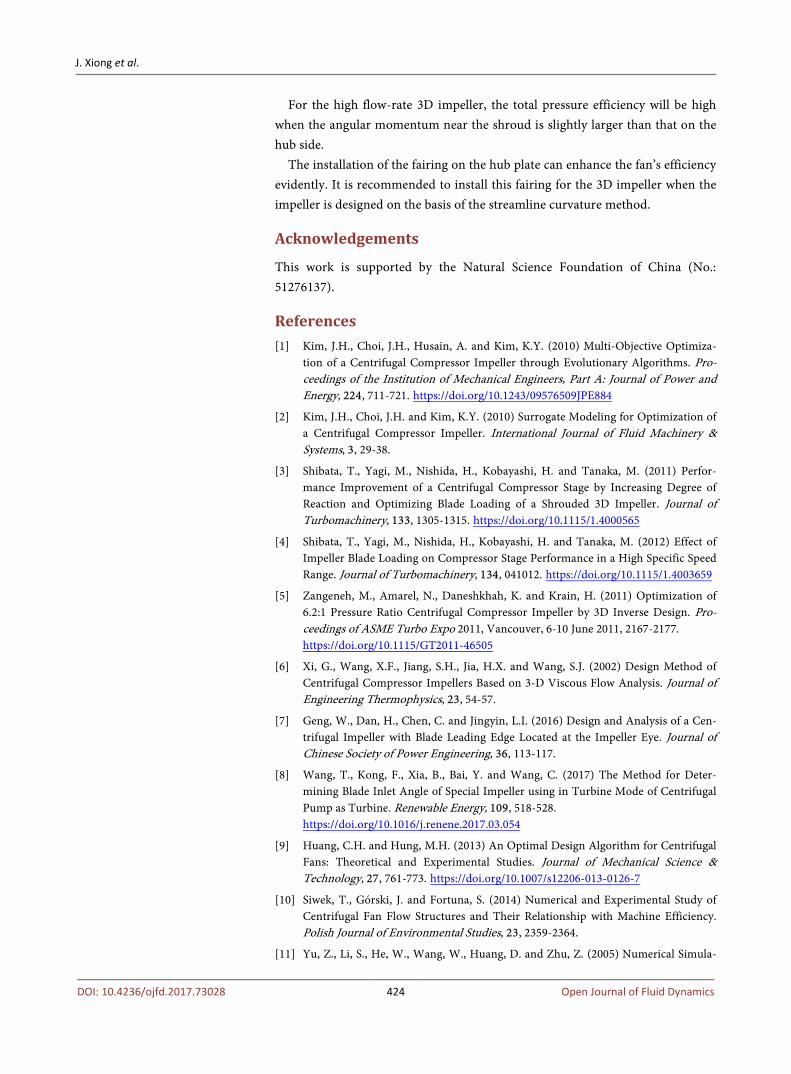
The designed fan has been manufactured, as shown in Figure 13. The proto-type of Scheme 9 has been tested in a company’s test rig. The test results agree well with the simulated performance, but the detailed data were kept in the company and is not given to us.
4. Conclusions
In this paper, a high flow-rate centrifugal fan with a 3D impeller is designed. The main dimensions of the impeller were firstly determined by using the conven-tional methods. Then the shape of the 3D blade was designed by prescribing the blade loading, or the angular momentum, along the blade meridional stream-lines, in combination with the streamline curvature method. The aerodynamic performance of the designed fan was obtained by numerical simulations and a high-efficiency 3D fan was successfully designed. In the design process, the in-fluence of some key parameters was compared and analyzed. Some conclusions are obtained as follows:
For a high flow-rate impeller, the blade passage is usually short. The calcu-lated separation radius is often too small by using the common Stanitz equation. It is suggested to use the Stanitz correction equation to determine the separation radius which is the starting point to consider the slip effect of the flow in the impeller. The numerical results show that the aerodynamic performance of the 3D fan can be improved with further properly increasing the separation radius. Table 6. Aerodynamic performance of different schemes.
Scheme number 7 8 9 10
2 2u uc c′ 0.7 0.65 0.6 0.57
A/m 0.165 0.175 0.19 0.2
Total pressure of fan (Pa) 1196 1196 1211 1205
Total pressure efficiency of fan 0.8521 0.8547 0.8610 0.8582
Total pressure rise of impeller (Pa) 1340 1340 1345 1341
Total pressure efficiency of impeller 0.9547 0.9576 0.9562 0.9550
Internal power (W) 858.59 855.94 860.38 858.93
J. Xiong et al.
DOI: 10.4236/ojfd.2017.73028 423 Open Journal of Fluid Dynamics
(a)
(b)
Figure 12. Total pressure contour and streamline of the Scheme 9: (a) Pressure contour; (b) Streamline field.
(a) (b)
Figure 13. The prototype of Scheme 9: (a) The impeller; (b) Assembly of the fan.
J. Xiong et al.
DOI: 10.4236/ojfd.2017.73028 424 Open Journal of Fluid Dynamics
For the high flow-rate 3D impeller, the total pressure efficiency will be high when the angular momentum near the shroud is slightly larger than that on the hub side.
The installation of the fairing on the hub plate can enhance the fan’s efficiency evidently. It is recommended to install this fairing for the 3D impeller when the impeller is designed on the basis of the streamline curvature method.
Acknowledgements
This work is supported by the Natural Science Foundation of China (No.: 51276137).
References [1] Kim, J.H., Choi, J.H., Husain, A. and Kim, K.Y. (2010) Multi-Objective Optimiza-
tion of a Centrifugal Compressor Impeller through Evolutionary Algorithms. Pro-ceedings of the Institution of Mechanical Engineers, Part A: Journal of Power and Energy, 224, 711-721. https://doi.org/10.1243/09576509JPE884
[2] Kim, J.H., Choi, J.H. and Kim, K.Y. (2010) Surrogate Modeling for Optimization of a Centrifugal Compressor Impeller. International Journal of Fluid Machinery & Systems, 3, 29-38.
[3] Shibata, T., Yagi, M., Nishida, H., Kobayashi, H. and Tanaka, M. (2011) Perfor-mance Improvement of a Centrifugal Compressor Stage by Increasing Degree of Reaction and Optimizing Blade Loading of a Shrouded 3D Impeller. Journal of Turbomachinery, 133, 1305-1315. https://doi.org/10.1115/1.4000565
[4] Shibata, T., Yagi, M., Nishida, H., Kobayashi, H. and Tanaka, M. (2012) Effect of Impeller Blade Loading on Compressor Stage Performance in a High Specific Speed Range. Journal of Turbomachinery, 134, 041012. https://doi.org/10.1115/1.4003659
[5] Zangeneh, M., Amarel, N., Daneshkhah, K. and Krain, H. (2011) Optimization of 6.2:1 Pressure Ratio Centrifugal Compressor Impeller by 3D Inverse Design. Pro-ceedings of ASME Turbo Expo 2011, Vancouver, 6-10 June 2011, 2167-2177. https://doi.org/10.1115/GT2011-46505
[6] Xi, G., Wang, X.F., Jiang, S.H., Jia, H.X. and Wang, S.J. (2002) Design Method of Centrifugal Compressor Impellers Based on 3-D Viscous Flow Analysis. Journal of Engineering Thermophysics, 23, 54-57.
[7] Geng, W., Dan, H., Chen, C. and Jingyin, L.I. (2016) Design and Analysis of a Cen-trifugal Impeller with Blade Leading Edge Located at the Impeller Eye. Journal of Chinese Society of Power Engineering, 36, 113-117.
[8] Wang, T., Kong, F., Xia, B., Bai, Y. and Wang, C. (2017) The Method for Deter-mining Blade Inlet Angle of Special Impeller using in Turbine Mode of Centrifugal Pump as Turbine. Renewable Energy, 109, 518-528. https://doi.org/10.1016/j.renene.2017.03.054
[9] Huang, C.H. and Hung, M.H. (2013) An Optimal Design Algorithm for Centrifugal Fans: Theoretical and Experimental Studies. Journal of Mechanical Science & Technology, 27, 761-773. https://doi.org/10.1007/s12206-013-0126-7
[10] Siwek, T., Górski, J. and Fortuna, S. (2014) Numerical and Experimental Study of Centrifugal Fan Flow Structures and Their Relationship with Machine Efficiency. Polish Journal of Environmental Studies, 23, 2359-2364.
[11] Yu, Z., Li, S., He, W., Wang, W., Huang, D. and Zhu, Z. (2005) Numerical Simula-
J. Xiong et al.
DOI: 10.4236/ojfd.2017.73028 425 Open Journal of Fluid Dynamics
tion of Flow Field for a Whole Centrifugal Fan and Analysis of the Effects of Blade Inlet Angle and Impeller Gap. HVAC&R Research, 11, 263-283. https://doi.org/10.1080/10789669.2005.10391137
[12] Aldi, N., Davoli, G., Pinelli, M., Rossi, L. and Suman, A. (2016) Eco-Design of a Small Size Industrial Fan for Ceramic Tile Cooling. Proceedings of the Institution of Mechanical Engineers, Part A: Journal of Power and Energy, 230, 502-511. https://doi.org/10.1177/0957650916631668
[13] Heo, M.W., Kim, J.H. and Kim, K.-Y. (2015) Design Optimization of a Centrifugal Fan with Splitter Blades. International Journal of Turbo & Jet-Engines, 32, 143-154. https://doi.org/10.1515/tjj-2014-0026
[14] Tsai, B.J. and Wu, C.L. (2007) Investigation of a Miniature Centrifugal Fan. Applied Thermal Engineering, 27, 229-239. https://doi.org/10.1016/j.applthermaleng.2006.04.028
[15] Lee, M.J., Song, W.S., Jo, H.J., Choi, K.B., Park, D.J. and Lee, S. (2010) Aerodynamic Design of Slim and High-Efficient Turbo-Fan. American Institute of Physics, 1225, 725-731.
[16] Kruyt, N.P. and Westra, R.W. (2014) On the Inverse Problem of Blade Design for Centrifugal Pumps and Fans. Inverse Problems, 30, 1-22. https://doi.org/10.1088/0266-5611/30/6/065003
Submit or recommend next manuscript to SCIRP and we will provide best service for you:
Accepting pre-submission inquiries through Email, Facebook, LinkedIn, Twitter, etc. A wide selection of journals (inclusive of 9 subjects, more than 200 journals) Providing 24-hour high-quality service User-friendly online submission system Fair and swift peer-review system Efficient typesetting and proofreading procedure Display of the result of downloads and visits, as well as the number of cited articles Maximum dissemination of your research work
Submit your manuscript at: http://papersubmission.scirp.org/ Or contact [email protected]