Embed Size (px)
Citation preview
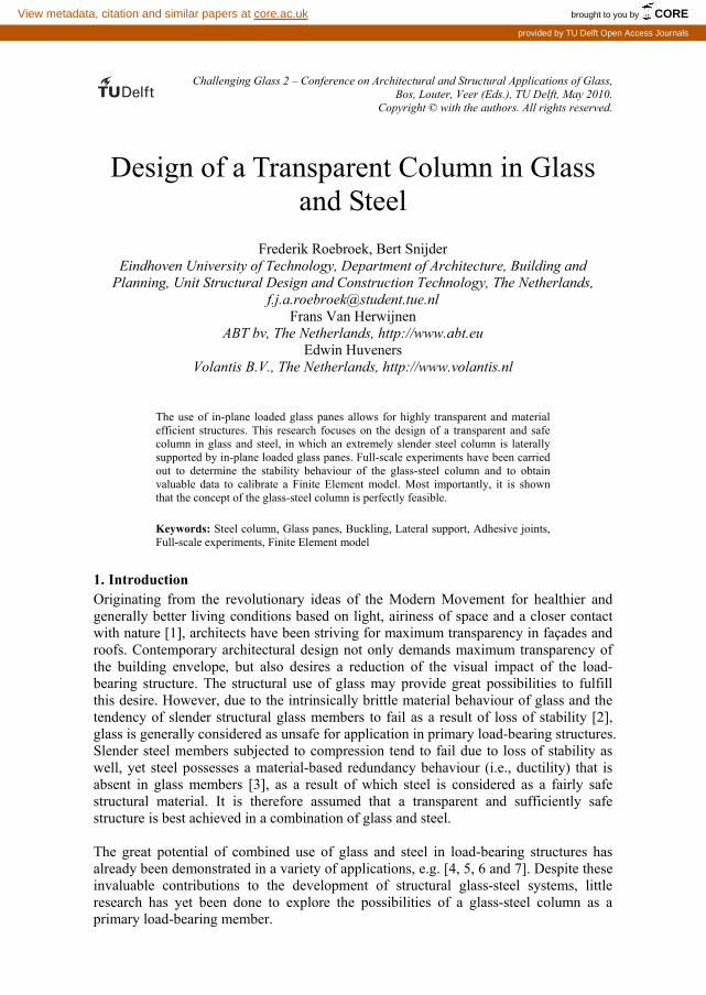
Challenging Glass 2 – Conference on Architectural and Structural Applications of Glass, Bos, Louter, Veer (Eds.), TU Delft, May 2010.
Copyright © with the authors. All rights reserved.
Design of a Transparent Column in Glass and Steel
Frederik Roebroek, Bert Snijder Eindhoven University of Technology, Department of Architecture, Building and
Planning, Unit Structural Design and Construction Technology, The Netherlands, [email protected]
Frans Van Herwijnen ABT bv, The Netherlands, http://www.abt.eu
Edwin Huveners Volantis B.V., The Netherlands, http://www.volantis.nl
The use of in-plane loaded glass panes allows for highly transparent and material efficient structures. This research focuses on the design of a transparent and safe column in glass and steel, in which an extremely slender steel column is laterally supported by in-plane loaded glass panes. Full-scale experiments have been carried out to determine the stability behaviour of the glass-steel column and to obtain valuable data to calibrate a Finite Element model. Most importantly, it is shown that the concept of the glass-steel column is perfectly feasible.
Keywords: Steel column, Glass panes, Buckling, Lateral support, Adhesive joints, Full-scale experiments, Finite Element model
1. Introduction Originating from the revolutionary ideas of the Modern Movement for healthier and generally better living conditions based on light, airiness of space and a closer contact with nature [1], architects have been striving for maximum transparency in façades and roofs. Contemporary architectural design not only demands maximum transparency of the building envelope, but also desires a reduction of the visual impact of the load-bearing structure. The structural use of glass may provide great possibilities to fulfill this desire. However, due to the intrinsically brittle material behaviour of glass and the tendency of slender structural glass members to fail as a result of loss of stability [2], glass is generally considered as unsafe for application in primary load-bearing structures. Slender steel members subjected to compression tend to fail due to loss of stability as well, yet steel possesses a material-based redundancy behaviour (i.e., ductility) that is absent in glass members [3], as a result of which steel is considered as a fairly safe structural material. It is therefore assumed that a transparent and sufficiently safe structure is best achieved in a combination of glass and steel. The great potential of combined use of glass and steel in load-bearing structures has already been demonstrated in a variety of applications, e.g. [4, 5, 6 and 7]. Despite these invaluable contributions to the development of structural glass-steel systems, little research has yet been done to explore the possibilities of a glass-steel column as a primary load-bearing member.
brought to you by COREView metadata, citation and similar papers at core.ac.uk
provided by TU Delft Open Access Journals

Challenging Glass 2
The research presented here is aimed at designing a transparent column of glass and steel, in which an axially loaded slender steel column is laterally supported by glass panes, thus resulting in an optimum utilisation of the axial load-bearing capacity of the steel column as well as sufficient structural safety against sudden failure. The main focus is on investigating the feasibility of the glass-steel column concept through the determination of the global structural behaviour obtained from full-scale experiments, as well as calibrating a Finite Element model based on experimental data.
2. Design Several column configurations were designed and evaluated. As the glass-steel column was to be designed in such a way that it fulfilled structural, functional and aesthetic requirements, a set of evaluation criteria was made on the basis of which the most promising configuration of the glass-steel column was selected for further research. The most important requirements included the use of plane glass panes, which essentially limited the cross-sectional typologies to either a cruciform or box-shape configuration. Equally important was to establish a column configuration in which the axial load applied to the top of the steel column section was prevented from spreading to the glass panes as to achieve an optimum utilisation of the axial load-bearing capacity of the steel column. The column configuration eventually selected is characterised by a cruciform cross-sectional shape consisting of a single solid square steel section onto which four glass panes are connected in both orthogonal directions of the cross-sectional plane (Figure 1). This way, the glass panes will be primarily subjected to in-plane bending and shear. A solid square steel section was selected as it prevents the slender steel column from being susceptible to torsional buckling. Besides, it provides for a very small ratio of outer perimeter over cross-sectional area as a result of which the visual impact of the steel column is limited to a minimum. Figures 2 and 3 show possible glass-steel columns based on the selected configuration.
Figure 1: Selected configuration. Figure 2: Column I. Figure 3: Column II.
The column presented in Figure 2 consists of a four large glass panes, one at each side. Intermediate support to the steel column is provided by contact elements. The design is highly transparent, but provides little structural safety. Figure 3 shows a column that

Design of a Transparent Column in Glass and Steel
consists of multiple small glass panes at each side of the steel column. The glass panes are connected to the steel column through steel strips and adhesive bonded joints that allow for a better (i.e., more uniform) stress distribution [8]. Moreover, this design may allow for a significant residual load-bearing capacity upon breakage of one or more glass panes, as the glass panes at opposite sides of the steel column can contribute to the stability of the column. It is therefore that this glass-steel column design was selected for further research. For the purpose of preliminary design, an arbitrary design load of 550kN was assumed based on a typical incidental combination of dead load and live load on a single office building floor with a fairly customary grid of vertical supports.
3. Experiments
3.1. Test program Full-scale experiments were carried out to gain understanding of the stability behaviour of the glass-steel column. Besides, the experiments were aimed at obtaining valuable input for Finite Element (FE) calculations. The test program consisted of three distinct experiments, though all of which on an axially loaded solid square steel column that was laterally supported by glass panes in only one direction. The specimens varied in the defined in-plane initial out-of-straightness of the steel column and the width of the glass panes (Figure 4 and Table 1).
Figure 4: Schematic representation of the different test specimens.
Table 1: Variations in the geometry of the different test specimens.
Specimen Width of glass pane [mm] Out-of-straightness of steel column [mm]
1 550 16 (applied)
2 550 2 (as delivered)
3 350 16 (applied)
Figure 5 shows a typical test specimen with a length of 3700mm. The dimensions of the S235JR steel column were set based on a design load of 550kN. Along the length of the steel column, cold-formed steel strips were welded at regular intervals between which 19mm single annealed float glass panes were connected through an epoxy adhesive bond line of 0.5mm thickness. The glass pane width of test specimen 1 and 2 was selected such that the anticipated maximum in-plane tensile bending stress would not exceed 15N/mm2, whereas the glass pane width of test specimen 3 was selected based

Challenging Glass 2
on an anticipated maximum in-plane tensile bending stress in the glass pane of 45N/mm2, which would generally be sufficient to cause breakage of the glass panes prior to buckling of the steel column. The glass pane thickness of 19mm was deliberately chosen identical for each test specimen as it allowed for standardisation of the strips that were welded to the steel column section. Essential strength properties of the materials used in the test specimens are presented in Table 2. It is furthermore acknowledged that for safety reasons laminated safety glass should be used upon actual implementation of the glass-steel column. However, for the purpose of this research, single annealed float glass was used as it allowed for a better understanding of the global structural behaviour of the specimens, thereby ignoring any effect of the interlayer material of laminated glass.
Figure 5: Typical test specimen.
Table 2: Strength properties of the materials used in the test specimens.
Material Properties Remarks
Steel column: S235JR
fy;d = 215 N/mm2 fu;d = 360-510 N/mm2
Based on a nominal thickness ranging from 40 to 63mm
Steel strip: S235JRC+C
fy;d = 260 N/mm2 fu;d = 390-690 N/mm2
Based on a nominal thickness ranging from 16 to 40mm
Glass pane: annealed float glass
fg;k = 45 N/mm2 fmt;u;d = 25 N/mm2
Source: NEN 2608-2:2007 [9]
Adhesive joint: 3M Scotch-Weld 9323 B/A
τep;avg;k = 24 N/mm2 τep;u;k = 14 N/mm2
Determined experimentally [10]; Source: Product data sheet [11]
3.2. Test setup The test setup consisted of a very compact test rig in which the test specimens were positioned horizontally with the glass panes standing upright (Figure 6, 7, 8). Load introduction was established through a bearing block that was fitted to a 1000kN displacement controlled actuator. As the experiments were focussed on buckling of the steel column in the direction in which the column was laterally supported by glass panes, the test setup was designed such that the effective buckling length of the steel column in any other direction was effectively reduced. Additionally, great care was taken with respect to the design of the

Design of a Transparent Column in Glass and Steel
end supports and load application. In order to establish central load application and in-plane pin-ended conditions to the test specimens, a sliding bearing was designed made of a half cylindrical polytetrafluorethylene-based (PTFE-based) plain bushing and a notched shaft, which effectively resulted in very low rotational restraint [12].
Figure 6: Overview of the test rig and position of the specimen, measurement locations and numbering.
A separate measuring frame was installed so that the measurements at the specimens were unaffected by any deformation of the test setup. Lateral in-plane deformations of the steel column were measured at seven defined locations along the length of the column. Besides, the displacement of the bearing block at the side of the actuator was measured in the direction of loading. Strain was measured at the top and bottom surface at the middle of each unsupported length of the steel column (i.e., the length between the connecting elements of the single-sided lateral bracing system of glass panes), as well as at the front and back side of the glass pane surface at the locations of maximum bending stresses.
Figure 7: Specimen with temporary supports during curing of the epoxy adhesive.
Figure 8: Test rig and load introduction; the specimen is positioned horizontally.

Challenging Glass 2
3.3. Main observations In general, the experiments were performed successfully, though experiment 1 and 2 were subject to some irregularities. Immediately after the load started to build up, the actuator moved upwards about 1mm, causing the specimen to be lifted at one end. The influence can be clearly observed in the load-deformation graphs of Figure 9. The test specimen of experiment 1 consisted of an initially curved steel column, with a defined out-of-straightness of 16mm, and glass panes with a width of 550mm. Buckling occurred at the unsupported length closest to the load introduction. An ultimate load of 660kN was achieved, which is about 10 times larger than the ultimate load of a similar column without lateral support. The glass panes remained intact at a maximum tensile bending stress of 18.2 N/mm2, and damage to the glass panes was only found locally.
0
200
400
600
800
-7 -6 -5 -4 -3 -2 -1 0 1w [mm]
F [kN]
1-2-3-4-5-6-7
Experiment 1
0
200
400
600
800
-3 -2.5 -2 -1.5 -1 -0.5 0e [mm/m]
F [kN]
Experiment 1
bottom surface
top surface
1.
0
200
400
600
800
-0.2 -0.1 0 0.1 0.2e [mm/m]
F [kN]
Experiment 1
11B-10A-10B-11A
10.
11.
0
200
400
600
800
-5 -4 -3 -2 -1 0 1w [mm]
F [kN]
1-2-3-4-5-6-7
Experiment 2
0
200
400
600
800
-3 -2.5 -2 -1.5 -1 -0.5 0e [mm/m]
F [kN]
Experiment 2
bottom surface
top surface
1.
0
200
400
600
800
-0.2 -0.1 0 0.1 0.2e [mm/m]
F [kN]
Experiment 2
10A-10B-11B-11A
10.
11.
0
150
300
450
600
-4 -3 -2 -1 0 1w [mm]
F [kN]
4-3-5-1-2-6-7
Experiment 3
0
200
400
600
-3 -2.5 -2 -1.5 -1 -0.5 0e [mm/m]
F [kN]
Experiment 3
bottom surface
top surface
1.
0
150
300
450
600
-0.4 -0.2 0 0.2 0.4e [mm/m]
F [kN]
Experiment 3
12B-13A-12A-13B
11A-10B-10A-11B
10.
11.
12.
13.
Figure 9: Load-deformation graphs of the steel column at 7 locations; load-strain graphs of the steel column at location of maximum bending; load-strain graphs of the glass panes at location of maximum bending (i.e., edges). Measurement locations are indicated by diamond markers and numbers corresponding to Figure 6.

Design of a Transparent Column in Glass and Steel
The test specimen of experiment 2 consisted of a virtually straight steel column. The measured initial out-of-straightness was 2.3mm. Similar to experiment 1, glass panes with a width of 550mm were used. Again, buckling occurred at the unsupported length closest to the load introduction, yet at an ultimate load of 699kN. The maximum tensile bending stresses remained limited to about 7.7 N/mm2 and no glass damage was found. The test specimen of experiment 3 consisted of an initially curved steel column, with a defined out-of-straightness of 16mm, and glass panes with a width of 350mm. In contrast to the other experiments, failure occurred suddenly and unexpectedly due to simultaneous and complete breakage of all glass panes, causing the steel column to buckle over its entire length. An ultimate load of 490kN was recorded at a tensile stress of 22N/mm2, derived from measuring the strain at the edges of maximum bending of the glass panes. It is assumed that stresses were higher locally as a result of which the material capacity was exceeded and, consequently, stiffness was reduced. This may have led to a further increase of stresses and rapid crack propagation. Stills from a high speed camera seem to confirm this assumption.
4. Finite Element simulation
4.1. Objective A two-dimensional FE model based on the commercially available DIANA code [13] was developed for geometrical and material nonlinear analyses in order to simulate the experiments, as well as to corroborate and obtain additional understanding of the global structural behaviour of the glass-steel column. Results obtained from the full-scale experiments were used for calibration of the FE model.
4.2. Geometry and material definition of the FE model The steel column was modelled by beam elements based on Bernoulli theory. As the results obtained from full-scale experiments showed loading of the steel column beyond the elastic range of the material, a nonlinear material law was modelled. The steel strips were represented by beam elements as well, whereas the glass panes were modelled by eight-node plane stress elements. Linear elastic behaviour of glass was assumed (E = 70000N/mm2, ν = 0.23), thus not allowing for the simulation of cracking of glass. A structural line interface element was selected to represent the adhesive bonded joint. The assigned stress-relative displacement relations were assumed linear elastic (Figure 10) as the anticipated stresses in the adhesive bonded joint remained limited and well within the elastic range [14]. The column end conditions were represented by a roller and pinned connection provided with rotational and translational springs to account for respectively friction in the bearings and deflection of the test rig (Table 3).
Figure 10: Idealized material-law of the applied epoxy adhesive according to [14] (left); modelled linear elastic shear stress-relative displacement (middle) and normal stress-relative displacement behaviour (right).

Challenging Glass 2
Table 3: Element types and geometrical data.
Part Element type Element
name Width [mm]
Height [mm]
Thickness [mm]
Steel column Beam L7BEN 50 50 --
Steel strip Beam L7BEN 20 20 --
Glass pane Plane stress CQ16M -- -- 19
Adhesive bonded joint 2D Interface CL12I 19 -- 0.5
Rotational spring Discrete spring SP1RO -- -- --
Translational spring Discrete spring SP1TR -- -- --
4.3. Calibration The parameters for calibration of the FE model included the experimentally determined stress-strain relation of the steel column, the rotational end restraint of the steel column due to friction and the stiffness of the test rig (Table 4). In order to accurately represent the actual stress-strain relation obtained from tensile coupon testing, a multi-linear material-law was modelled through six stress-strain coordinates. The measured strain rate was taken into account [15], but was assumed constant. The rotational end restraint due to friction was modelled by an elastic rotational spring in which the spring stiffness related to a restraint parameter ρ. Although the actual degree of restraint was shown to be dependent on the applied axial load, the restraint parameter was assumed to be constant, at a value that corresponded to the frictional behaviour of the bearings under relatively high axial loads (i.e., larger than 100kN).
Table 4: Calibration parameters. Set 1 corresponds to experiment 1, etc.
Set Yield stress [N/mm2]
Rotational spring stiffness [kNm/rad]
Translational spring stiffness [kN/mm]
1 262.1 87.7 248.0
2 257.3 89.4 259.0
3 258.1 87.5 237.0
The calibrated FE model generally shows moderate to very good correspondence with experimental results (Figure 11). The load-deformation graphs correspond moderately due to significant deviations in the lateral in-plane deformations of the steel column at an initial stage of loading. Furthermore, the reduced stiffness of the specimen at about 350kN observed in experiments is not matched, probably due to the fact that residual stresses and assembly stresses were not incorporated in the FE model. Finally, the FE model underestimates the ultimate load, due to the fact that the actual strain rate measured in experiments increased substantially just prior to attainment of the ultimate load. Yet, for the FE models corresponding to experiment 1 and 2, the type and location of failure were in agreement with the respective experiments. In experiment 3, failure occurred unexpectedly due to complete and simultaneous breakage of all glass panes. Naturally, this type of failure was not obtained from the FE analysis, as a linear elastic material law was assigned to the glass panes.

Design of a Transparent Column in Glass and Steel
The FE model overestimated the maximum tensile bending stresses in the glass panes obtained from all experiments by up to 15.6%, whereas the stresses at the surfaces of minimum and maximum bending of the steel column were underestimated within 13.0% and overestimated within 6.2%.
0
200
400
600
800
-7 -6 -5 -4 -3 -2 -1 0w [mm]
F [kN]
Experiment 1
Final model C
1.
0
200
400
600
800
-300 -250 -200 -150 -100 -50 0s [N/mm 2 ]
F [kN]
Experiment 1
bottom surface
Final model C
top surface
1.
0
200
400
600
800
-20 -10 0 10 20s [N/mm 2 ]
F [kN]
Experiment 1
Final model C
10.
0
200
400
600
800
-5 -4 -3 -2 -1 0w [mm]
F [kN]
Experiment 2
Final model C
1.
0
200
400
600
800
-300 -250 -200 -150 -100 -50 0s [N/mm 2 ]
F [kN]
Experiment 2
bottom surface
Final model C
top surface
1.
0
200
400
600
800
-20 -10 0 10 20s [N/mm 2 ]
F [kN]
Experiment 2
Final model C
10.
0
200
400
600
800
-5 -4 -3 -2 -1 0w [mm]
F [kN]
Experiment 3
Final model C
4.
0
200
400
600
800
-300 -250 -200 -150 -100 -50 0s [N/mm 2 ]
F [kN]
Experiment 3
bottom surface
Final model C
top surface
1.
0
200
400
600
800
-40 -20 0 20 40s [N/mm 2 ]
F [kN]
Experiment 3
Final model C
10.12.
Figure 11: Experimental (solid lines) and numerical (box markers) results. Load-deformation graphs of the steel column at location of maximum lateral deformation; load-stress graphs of the steel column at location of
maximum bending; load-stress graphs of the glass pane at location of maximum bending (i.e., edges). The measurement locations are indicated by diamond markers and numbers corresponding to Figure 6.
5. Conclusions The research objective was to design a transparent column of glass and steel that fulfills the requirements for an optimal utilization of the axial load bearing capacity of the steel column section as well as sufficient structural safety against sudden failure. Based on the experimental and numerical research described in this paper, it can be concluded that a system of in-plane loaded glass panes is perfectly able to provide lateral support

Challenging Glass 2
to an axially loaded steel column, thereby substantially increasing the ultimate load of the steel column. The utilization of the axial load bearing capacity can thus be significantly improved. Obviously, an important condition to the ability of the system of in-plane loaded glass panes to provide lateral stability to the steel column is that the glass panes remain intact and do not break. In the case that the glass panes remain intact, consequence-based structural safety is achieved based on the implicit redundancy through the material behaviour of steel. It was shown in experiment 3 that immediate and complete failure of the single-sided laterally supported specimen occurred upon breakage of the glass panes. However, in the actual design, the steel column is laterally supported by glass panes at all four sides. It is therefore assumed that significant residual load bearing capacity may be attributed to the glass panes that remain intact upon breakage of one or more panes. It is recognized that additional research is required to confirm this assumption and quantify the level of residual load-bearing capacity at different stages of damage. Additional research is als needed to determine the fire resistance capacity of the glass-steel column.
6. Acknowledgements The author gratefully acknowledges the material support of Scheuten Glasgroep.
7. References [1] Rice, P.; Dutton, H., Structural Glass, E & FN Spon, London, United Kingdom, 1995. [2] Luible, A., Stabilität von Tragelementen aus Glas, PhD thesis EPFL 3014, Lausanne, Switzerland, 2004. [3] Bos, F., Towards a combined probabilistic/consequence-based safety approach of structural glass
members, Heron, 52 (1/2), pp. 59-86. [4] Englhardt, O.; Bergmeister, K., Hybrid structural elements – an innovative high filigree glass-steel-
system, Proceedings of the 10th Glass Processing Days Conference, Tampere, Finland, 2007. [5] Wellershoff, F.; Sedlacek, G., Structural Use of Glass in Hybrid Elements: Steel-Glass-Beams, Glass-
GFRP-Plates, Proceedings of the 8th Glass Processing Days Conference, Tampere, Finland, 2003. [6] Weller, B.; Reich, S., Transparent roofs as space grid structures with steel-glass-modules, Proceedings
of the 10th Glass Processing Days Conference, Tampere, Finland, 2007. [7] Louter, C.; Belis, J.; Bos, F.; Veer, F.; Hobbelman, G., Reinforced Glass Cantilever Beams, Proceedings
of the 9th Glass Processing Days Conference, Tampere, Finland, 2005. [8] Weller, B.; Tasche, S., Strukturelles Kleben im Konstruktiven Glasbau, Stahlbau Spezial – Konstruktiver
Glasbau, 1/2008, pp. 28-33. [9] NEN 2608-2:2007, Vlakglas voor gebouwen – Dl. 2: Niet-verticaal geplaatst glas - Weerstand tegen
windbelasting, sneeuw, eigen gewicht - Eisen en bepalingsmethode, Nederlands Normalisatie Instituut, Delft, 2007.
[10] Huveners, E.; Koggel, B., Tensile Shear Tests for the Determination of the Shear-Strain Diagram of Several Adhesive Types, Report TUE O-2006.11, Eindhoven, The Netherlands, 2006.
[11] 3M, 3M Scotch-Weld 9323 B/A Structural Adhesive – Product Data Sheet, 3M United Kingdom PLC, Manchester, United Kingdom, 1996.
[12] Roebroek, F., Design of a transparent column in glass and steel, Master’s thesis TUE, Eindhoven, The Netherlands, 2010.
[13] TNO DIANA, DIANA Finite Element Analysis – User’s Manual – Release 9.2, TNO DIANA bv., Delft, The Netherlands, 2007.
[14] Huveners, E.; Hofmeyer, H.; Van Herwijnen, F.; Soetens, F., Numerical Research on Glass Panes Acting as a Shear Wall, Proceedings of the 1st Challenging Glass Conference, Delft, The Netherlands, 2008.
[15] Galambos, T., Guide to Stability Design Criteria for Metal Structures, John Wiley & Sons, New York, United States of America, 1988.