Embed Size (px)
Citation preview

Proceedings of the 2018 ASEE North Central Section Conference Copyright © 2018, American Society for Engineering Education
1
Design of a Two-Axis Shaking Table to Simulate Earthquakes in an
Educational Setting
Amy Tabar, Gabriel Russ, and Bryan Mason College of Engineering
Ohio Northern University Ada, Ohio 45810
Email: [email protected]
Introduction
Earthquake strikes are a destructive, costly, and deadly force. High magnitude
earthquakes in heavily populated areas historically cause thousands of deaths that could be
prevented if buildings were better made to resist such strong forces. The cost of repair and clean
up cost often extends into the tens of millions7.
The design of an earthquake simulation table that can be used in educational settings has
been assigned as an undergraduate senior capstone project. The table will be used to analyze the
effect of earthquake forces on smart structures to help develop an understanding of the effect of
earthquake forces and design earthquake-resistant designs in architecture. Our client has
requested that the simulation table be able to emulate real-time earthquake data in two horizontal
directions (X,Y) in a strict budget. We have defined the problem, gathered information,
generated alternatives, evaluated potential solutions, and have a proposed design for the machine.
Problem Definition
According to the Center for Research on the Epidemiology of Natural Disasters,
approximately 121 million people are affected by earthquake strikes, and caused as many as
750,000 deaths between 1994 to 2013. About 55% of people are killed by earthquakes, more
than any other types of natural disaster, and cost more than $700 billion in damages. The
National Earthquake Information Center locates about 30,000 earthquakes each year. A system is
needed to study the stability of structures during the earthquake strikes to minimize damages.
The machine created by our team is to be used as an educational tool in earthquake
science. An affordable shaking table that accurately emulates earthquake forces could be
Proceedings of the 2018 ASEE North Central Section Conference Copyright © 2018, American Society for Engineering Education
2
valuable to children’s science museums, primary and secondary schools, and universities.
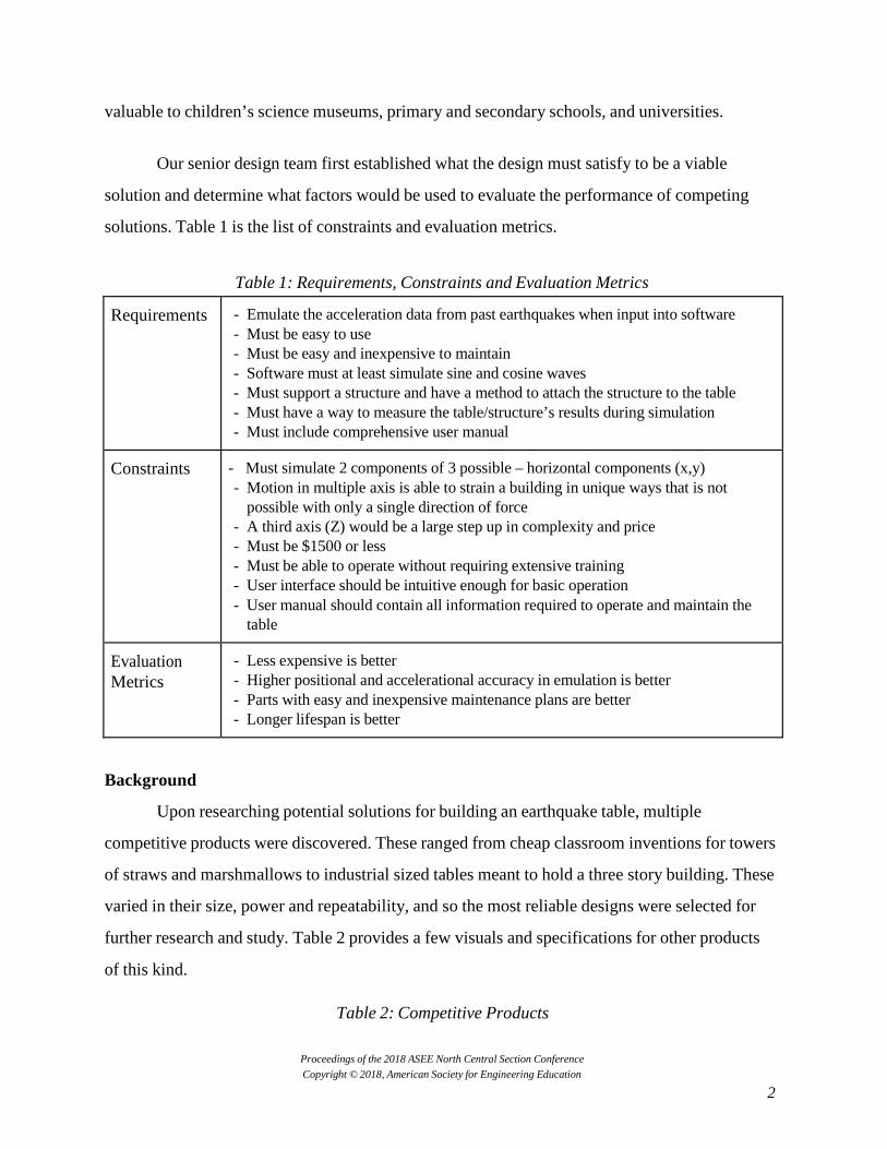
Our senior design team first established what the design must satisfy to be a viable
solution and determine what factors would be used to evaluate the performance of competing
solutions. Table 1 is the list of constraints and evaluation metrics.
Table 1: Requirements, Constraints and Evaluation Metrics
Requirements - Emulate the acceleration data from past earthquakes when input into software - Must be easy to use - Must be easy and inexpensive to maintain - Software must at least simulate sine and cosine waves - Must support a structure and have a method to attach the structure to the table - Must have a way to measure the table/structure’s results during simulation - Must include comprehensive user manual
Constraints - Must simulate 2 components of 3 possible – horizontal components (x,y) - Motion in multiple axis is able to strain a building in unique ways that is not
possible with only a single direction of force - A third axis (Z) would be a large step up in complexity and price - Must be $1500 or less - Must be able to operate without requiring extensive training - User interface should be intuitive enough for basic operation - User manual should contain all information required to operate and maintain the
table
Evaluation Metrics
- Less expensive is better - Higher positional and accelerational accuracy in emulation is better - Parts with easy and inexpensive maintenance plans are better - Longer lifespan is better
Background
Upon researching potential solutions for building an earthquake table, multiple
competitive products were discovered. These ranged from cheap classroom inventions for towers
of straws and marshmallows to industrial sized tables meant to hold a three story building. These
varied in their size, power and repeatability, and so the most reliable designs were selected for
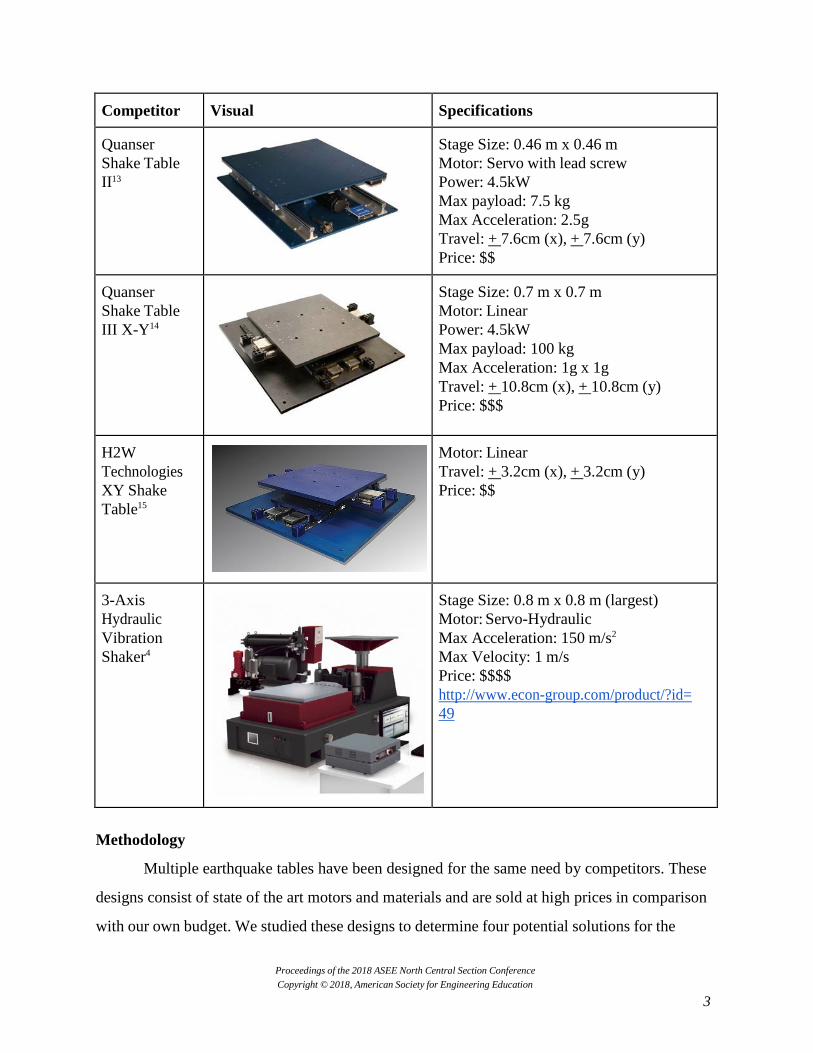
further research and study. Table 2 provides a few visuals and specifications for other products
of this kind.
Table 2: Competitive Products
Proceedings of the 2018 ASEE North Central Section Conference Copyright © 2018, American Society for Engineering Education
3
Competitor Visual Specifications
Quanser Shake Table II13
Stage Size: 0.46 m x 0.46 m Motor: Servo with lead screw Power: 4.5kW Max payload: 7.5 kg Max Acceleration: 2.5g Travel: + 7.6cm (x), + 7.6cm (y) Price: $$
Quanser Shake Table III X-Y14
Stage Size: 0.7 m x 0.7 m Motor: Linear Power: 4.5kW Max payload: 100 kg Max Acceleration: 1g x 1g Travel: + 10.8cm (x), + 10.8cm (y) Price: $$$
H2W Technologies XY Shake Table15
Motor: Linear Travel: + 3.2cm (x), + 3.2cm (y) Price: $$
3-Axis Hydraulic Vibration Shaker4
Stage Size: 0.8 m x 0.8 m (largest) Motor: Servo-Hydraulic Max Acceleration: 150 m/s2
Max Velocity: 1 m/s Price: $$$$ http://www.econ-group.com/product/?id= 49
Methodology
Multiple earthquake tables have been designed for the same need by competitors. These
designs consist of state of the art motors and materials and are sold at high prices in comparison
with our own budget. We studied these designs to determine four potential solutions for the
Proceedings of the 2018 ASEE North Central Section Conference Copyright © 2018, American Society for Engineering Education
4
primary component of the earthquake table, the motor. These are hydraulic, pneumatic, linear,
servo motor and ball screw, and servo motor with belt. We evaluated the solutions with four
evaluation metrics in mind: cost (40%), emulation accuracy (30%), lifespan (20%), and ease of
maintenance (10%). We determined that using a servo motor with a ball screw was the best
option for the given requirements.
Motor Selection
The competitive products helped our team develop a list of the required materials and
components that are required to fulfill the purpose of our table. What we learned is the primary
component in a table that can move in both horizontal directions is the method to convert
rotational motion into linear motion. We looked extensively into four different possibilities.
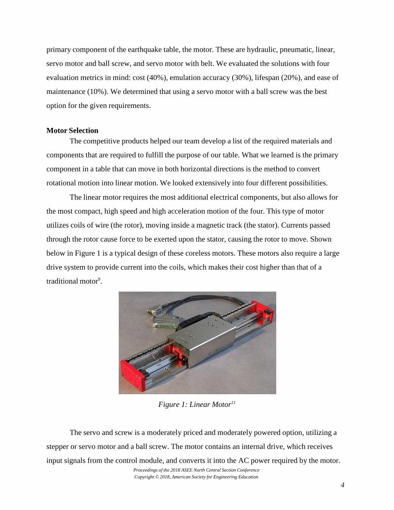
The linear motor requires the most additional electrical components, but also allows for
the most compact, high speed and high acceleration motion of the four. This type of motor
utilizes coils of wire (the rotor), moving inside a magnetic track (the stator). Currents passed
through the rotor cause force to be exerted upon the stator, causing the rotor to move. Shown
below in Figure 1 is a typical design of these coreless motors. These motors also require a large
drive system to provide current into the coils, which makes their cost higher than that of a
traditional motor9.
Figure 1: Linear Motor11
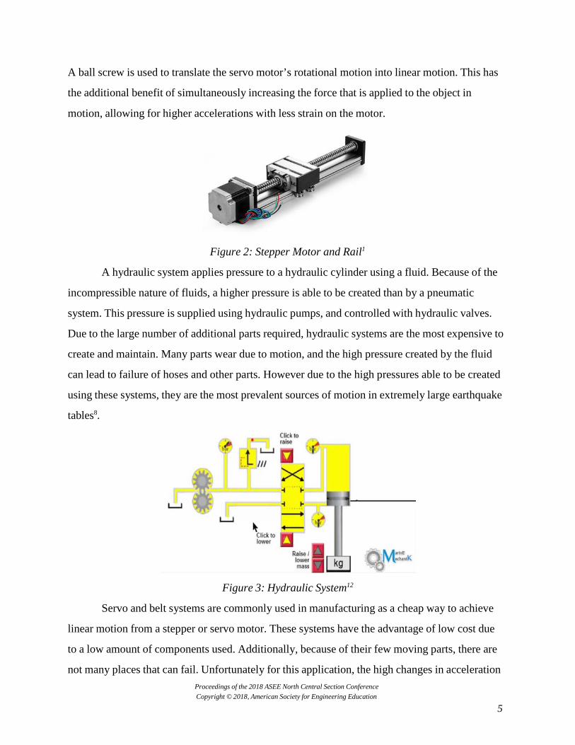
The servo and screw is a moderately priced and moderately powered option, utilizing a
stepper or servo motor and a ball screw. The motor contains an internal drive, which receives
input signals from the control module, and converts it into the AC power required by the motor.
Proceedings of the 2018 ASEE North Central Section Conference Copyright © 2018, American Society for Engineering Education
5
A ball screw is used to translate the servo motor’s rotational motion into linear motion. This has
the additional benefit of simultaneously increasing the force that is applied to the object in
motion, allowing for higher accelerations with less strain on the motor.
Figure 2: Stepper Motor and Rail1
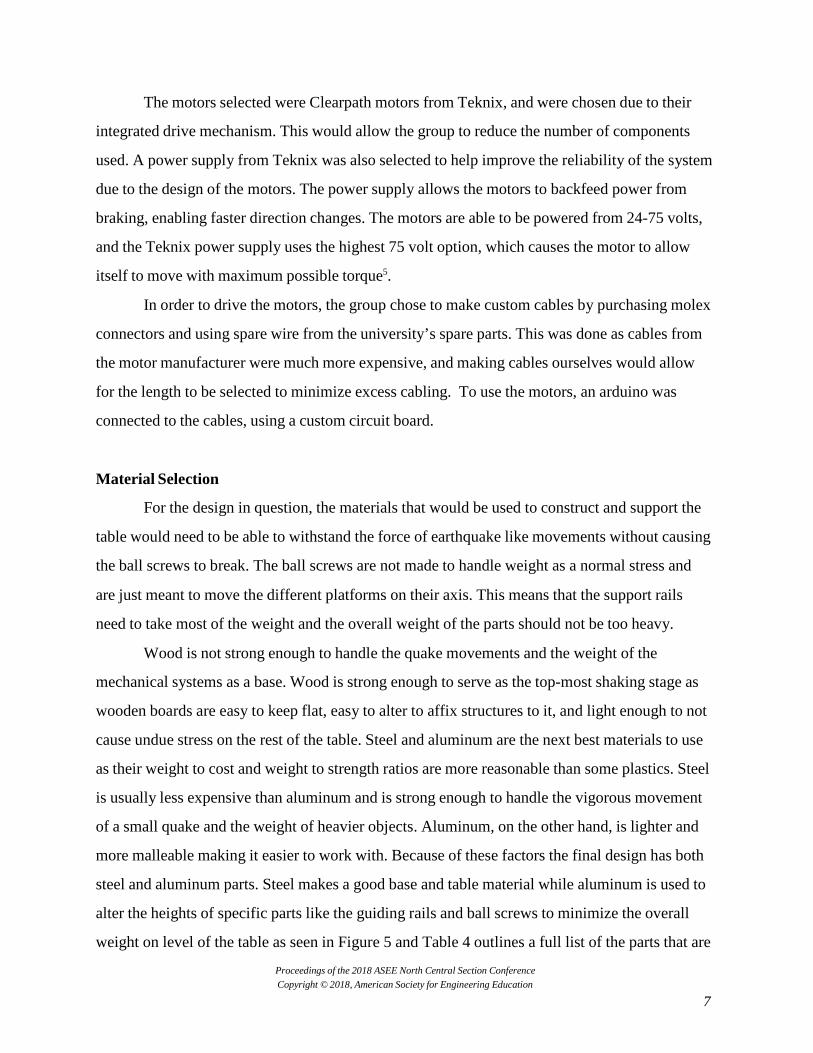
A hydraulic system applies pressure to a hydraulic cylinder using a fluid. Because of the
incompressible nature of fluids, a higher pressure is able to be created than by a pneumatic
system. This pressure is supplied using hydraulic pumps, and controlled with hydraulic valves.
Due to the large number of additional parts required, hydraulic systems are the most expensive to
create and maintain. Many parts wear due to motion, and the high pressure created by the fluid
can lead to failure of hoses and other parts. However due to the high pressures able to be created
using these systems, they are the most prevalent sources of motion in extremely large earthquake
tables8.
Figure 3: Hydraulic System12
Servo and belt systems are commonly used in manufacturing as a cheap way to achieve
linear motion from a stepper or servo motor. These systems have the advantage of low cost due
to a low amount of components used. Additionally, because of their few moving parts, there are
not many places that can fail. Unfortunately for this application, the high changes in acceleration

Proceedings of the 2018 ASEE North Central Section Conference Copyright © 2018, American Society for Engineering Education
6
would put high strain on belts, causing them to wear and fail prematurely2.
Figure 4: Servo and Belt System3
Table 3 provides a list of the different motor and the specialized components that are
associated with them. As the primary constraint is cost, we put an approximate cost on each
different motor and its components. Much of this information was not available on the internet,
so we contacted multiple supply companies that could provide a quote. A linear motor supplier
was able to quote a cost half of what is usual in support of the purpose of the project.
Table 3: Specialized Components Required and Approximate Cost for a Single Axis
Linear Motor Stator Rotor Linear Motor Drive
Power Supply
$1648 $470.90 531.45 $316.80 $328.89
Servo & Screw
Servo Ballscrew Power Supply
$748 $349 $200 $199 Hydraulic Hydraulic
Pump Hydraulic
Valve Hydraulic Cylinder
Pressure Gauges
$2496 $725 $249 $1322 $200 Servo & Belt Servo Belt & Pulley Power Supply
$698 $349 $150 $199
Once the drive type was selected, the specific type of motor used needed to be selected.
These motors had to meet several requirements. The motors needed to be somewhat low cost, as
they would be a large portion of the overall project’s final total. Additionally, to keep the control
system from requiring to do a great deal of extra computation the motors should have a simple to
interface drive. Finally the motors needed to have the most possible output power to allow the
table to move with the required velocity.
Proceedings of the 2018 ASEE North Central Section Conference Copyright © 2018, American Society for Engineering Education
7
The motors selected were Clearpath motors from Teknix, and were chosen due to their
integrated drive mechanism. This would allow the group to reduce the number of components
used. A power supply from Teknix was also selected to help improve the reliability of the system
due to the design of the motors. The power supply allows the motors to backfeed power from
braking, enabling faster direction changes. The motors are able to be powered from 24-75 volts,
and the Teknix power supply uses the highest 75 volt option, which causes the motor to allow
itself to move with maximum possible torque5.
In order to drive the motors, the group chose to make custom cables by purchasing molex
connectors and using spare wire from the university’s spare parts. This was done as cables from
the motor manufacturer were much more expensive, and making cables ourselves would allow
for the length to be selected to minimize excess cabling. To use the motors, an arduino was
connected to the cables, using a custom circuit board.
Material Selection
For the design in question, the materials that would be used to construct and support the
table would need to be able to withstand the force of earthquake like movements without causing
the ball screws to break. The ball screws are not made to handle weight as a normal stress and
are just meant to move the different platforms on their axis. This means that the support rails
need to take most of the weight and the overall weight of the parts should not be too heavy.
Wood is not strong enough to handle the quake movements and the weight of the
mechanical systems as a base. Wood is strong enough to serve as the top-most shaking stage as
wooden boards are easy to keep flat, easy to alter to affix structures to it, and light enough to not
cause undue stress on the rest of the table. Steel and aluminum are the next best materials to use
as their weight to cost and weight to strength ratios are more reasonable than some plastics. Steel
is usually less expensive than aluminum and is strong enough to handle the vigorous movement
of a small quake and the weight of heavier objects. Aluminum, on the other hand, is lighter and
more malleable making it easier to work with. Because of these factors the final design has both
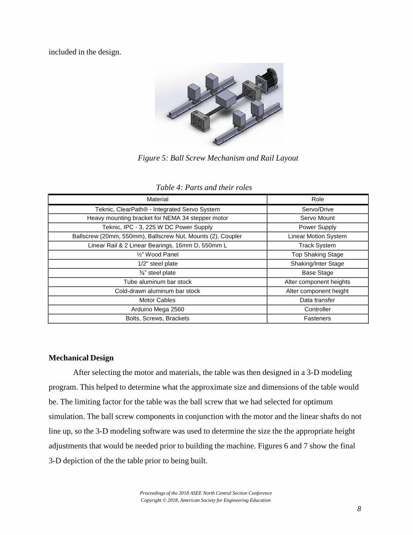
steel and aluminum parts. Steel makes a good base and table material while aluminum is used to
alter the heights of specific parts like the guiding rails and ball screws to minimize the overall
weight on level of the table as seen in Figure 5 and Table 4 outlines a full list of the parts that are
Proceedings of the 2018 ASEE North Central Section Conference Copyright © 2018, American Society for Engineering Education
8
included in the design.
Figure 5: Ball Screw Mechanism and Rail Layout
Table 4: Parts and their roles
Material Role Teknic, ClearPath® - Integrated Servo System Servo/Drive
Heavy mounting bracket for NEMA 34 stepper motor Servo Mount Teknic, IPC - 3, 225 W DC Power Supply Power Supply
Ballscrew (20mm, 550mm), Ballscrew Nut, Mounts (2), Coupler Linear Motion System Linear Rail & 2 Linear Bearings, 16mm D, 550mm L Track System
½” Wood Panel Top Shaking Stage 1/2" steel plate Shaking/Inter Stage ⅜” steel plate Base Stage
Tube aluminum bar stock Alter component heights Cold-drawn aluminum bar stock Alter component height
Motor Cables Data transfer Arduino Mega 2560 Controller
Bolts, Screws, Brackets Fasteners Mechanical Design
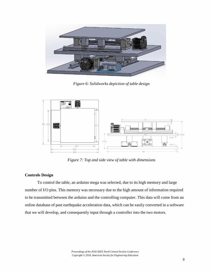
After selecting the motor and materials, the table was then designed in a 3-D modeling
program. This helped to determine what the approximate size and dimensions of the table would
be. The limiting factor for the table was the ball screw that we had selected for optimum
simulation. The ball screw components in conjunction with the motor and the linear shafts do not
line up, so the 3-D modeling software was used to determine the size the the appropriate height
adjustments that would be needed prior to building the machine. Figures 6 and 7 show the final
3-D depiction of the the table prior to being built.
Proceedings of the 2018 ASEE North Central Section Conference Copyright © 2018, American Society for Engineering Education
9
Figure 6: Solidworks depiction of table design
Figure 7: Top and side view of table with dimensions Controls Design
To control the table, an arduino mega was selected, due to its high memory and large
number of I/O pins. This memory was necessary due to the high amount of information required
to be transmitted between the arduino and the controlling computer. This data will come from an
online database of past earthquake acceleration data, which can be easily converted in a software
that we will develop, and consequently input through a controller into the two motors.

Proceedings of the 2018 ASEE North Central Section Conference Copyright © 2018, American Society for Engineering Education
10
Figure 8: Controller
Figure 9: Example of recorded earthquake data that will be simulated10
This database, the Ground Motion Database, is produced by the Pacific Earthquake
Engineering Research Center. This database has searchable acceleration data for thousands of
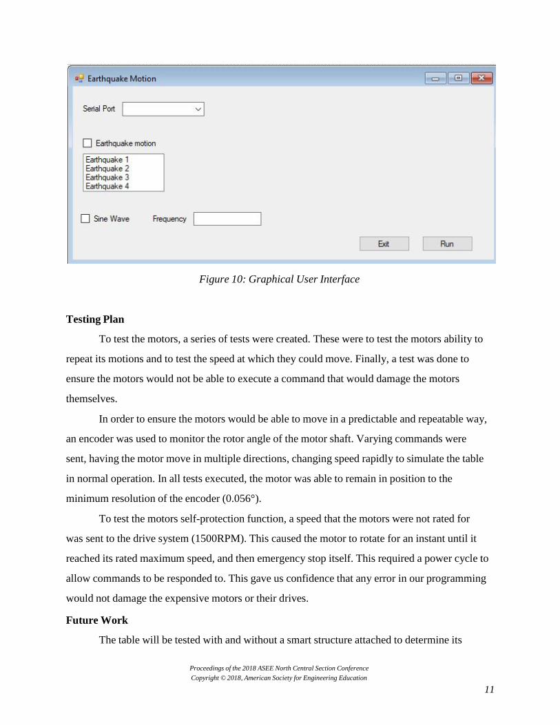
actual earthquakes, in a wide range of magnitudes10. The GUI is used to handle the motion of the
table and plot the effect caused by the motion. The GUI that we are designing will allow the user
to select whether to simulate past earthquake acceleration recorded data or to generate a sine
wave signal. The user will also be able to run the software and see the effect of the motion on the
structure. Figure 10 shows a flowchart of the graphical user interface.
Proceedings of the 2018 ASEE North Central Section Conference Copyright © 2018, American Society for Engineering Education
11
Figure 10: Graphical User Interface Testing Plan
To test the motors, a series of tests were created. These were to test the motors ability to
repeat its motions and to test the speed at which they could move. Finally, a test was done to
ensure the motors would not be able to execute a command that would damage the motors
themselves.
In order to ensure the motors would be able to move in a predictable and repeatable way,
an encoder was used to monitor the rotor angle of the motor shaft. Varying commands were
sent, having the motor move in multiple directions, changing speed rapidly to simulate the table
in normal operation. In all tests executed, the motor was able to remain in position to the
minimum resolution of the encoder (0.056°).
To test the motors self-protection function, a speed that the motors were not rated for
was sent to the drive system (1500RPM). This caused the motor to rotate for an instant until it
reached its rated maximum speed, and then emergency stop itself. This required a power cycle to
allow commands to be responded to. This gave us confidence that any error in our programming
would not damage the expensive motors or their drives.
Future Work
The table will be tested with and without a smart structure attached to determine its
Proceedings of the 2018 ASEE North Central Section Conference Copyright © 2018, American Society for Engineering Education
12
accuracy and maximum limits of acceleration and payload. The specifications and method for
using the machine will be carefully outlined in an instruction manual. The primary goal for this
table is to make it as accurate and user-friendly as possible.
Bibliography
[1] “Ballscrew and Stepper Motor”. AliExpress. Web. November 2017. <https://www.aliexpress.com/store/product/1pcs-Module-with-1605-ballscrew-stepper-motor-linear-rail-slider-linea r-guider-travel-500mm-linear-actuator/119347_2052910268.html>.
[2] Bartos, Brooke. “Strengths & Limitations: Belt Drive vs. Ball Screw Actuators”. Misumi. Web. May 2015. October 2015. <http://blog.misumiusa.com/strengths-limitations-belt-drive-vs-ball-screw-actuators/>.
[3] “Belt and Servo” Automation4Less. Web. October 2017. <http://www.automation4less.com/store/proddetail.asp?prod=MSA-628-2000/CM200>.
[4] "Cartesian Planar Systems." Air Bearing XY Table. IntelLiDrives, n.d. Web. 3 Sept. 2017. <http://www.intellidrives.com/Air-Bearing-XY-Tables-Planar-Systems>.
[5] “Clearpath Integrated Servo Motors”. Teknc.com. Web. October 2017. <https://www.teknic.com/products/clearpath-brushless-dc-servo-motors/clearpath-servos/>.
[6] "Earthquake Engineering." Earthquake Engineering Lab Solutions. Quanser, n.d. Web. 10 Sept. 2017. <https://www.quanser.com/solution/earthquake-engineering/>.
[7] Facts and Statistics: Earthquakes and Tsunamis. Insurance Information Institute. 2017. Accessed Sep 2017. <https://www.iii.org/fact-statistic/facts-statistics-earthquakes-and-tsunamis>.
[8] “Fundamentals of Hydraulic Motors”. Hydraulics and Motors. Web. October 2017. <http://www.hydraulicspneumatics.com/hydraulic-pumps-motors/fundamentals-hydraulic-motor>.
[9] “Linear Motors”. LinMot.com. Web. November 2017. <http://www.linmot.com/products/linear-motors/>.
[10] Peer Ground Motion Database. Pacific Earthquake Engineering Research Center. 2013. Accessed Sep. 2017. <https://ngawest2.berkeley.edu/>.
[11] “Schneeberger’s P3 Linear Motor Actuator”. Design World. Web. 24 Oct. 2017. <https://www.designworldonline.com/schneebergers-p3-linear-motor-actuator/>.
[12] “Simple Hydraulic system working and simulation”. Youtube.com. Web Video. October 2017. <https://www.youtube.com/watch?v=kzqkPx8F3D8>.
[13] “Quanser Shake Table II” Quanser Earthquake Engineering. Web. 10 Sept. 2017. <https://www.quanser.com/products/shake-table-ii/>.
[14] “Quanser Shake Table III X-Y” Quanser Earthquake Engineering. Web. 10 Sept. 2017.
Proceedings of the 2018 ASEE North Central Section Conference Copyright © 2018, American Society for Engineering Education
13
<https://www.quanser.com/products/shake-table-iii-xy/>.
[15] "XY Shake Table by H2W Technologies to Simulate Earthquakes." MotionControl.com. Motion WWWControl, 24 Oct. 2010. Web. 5 Sept. 2017. <https://www.motioncontrol.com/products/xy-shake-table-by-h2w-technologies-to-simulate-earthquakes/>.