Embed Size (px)
Citation preview
Page 1
DESIGN OF A WEIR The purpose of this exercise is to acquaint with the basic scope of a small weir calculation. It must cover the following topics: Calculation part (calculations should be illustrated with sketches):
- designation of spillway width, - selecting the shape of the spillway (trapezoidal), - calculation of stilling basin (length and depht), - calculation of the seepage in weir’s subsoil, - checking the stability of weir’s body and stilling basin
Drawing part: - horizontal projection and cross section of the weir (scale 1:50 or 1:100)
Term: 15. January. 2013 SDF = Spillway design flood [m3/s] Max storage level = maximum storage elevation in the reservoir
No. Name River SDF [m3/s]
Aver. flow rate
[m3/s]
Max storage
level [m.a.s.l.]
Subsoil Class of hydro-
structure
decline of
water surface
i [-]
1 Alvaro Correa Andres Alcazar Pagona 28,00 6,00 93,50 Gravel IV 0,00050
2 Adan Gomez Roberto Lopez Pagona 26,00 5,50 93,20 Soft clay III 0,00053
3 Ana Lopez Val Irene Rivera Pagona 24,00 5,00 93,20
Sand-gravel
mix II 0,00055
4 Piotr Prus Marcin Mosiejko Pagona 22,00 4,50 92,90 Fine
sand II 0,00058
5 Krzysztof
Jednachowski Sergiusz Szreder
Pagona 20,00 4,00 93,20 Gravel IV 0,00060
6 Borys Sajko Irmina Byzdra Pagona 19,00 4,00 92,70
Sand-gravel
mix IV 0,00065
7 Samuel Rodriguez Inigo De la Calle Prosna 100,00 20,00 149,00 Gravel II 0,00045
Page 2
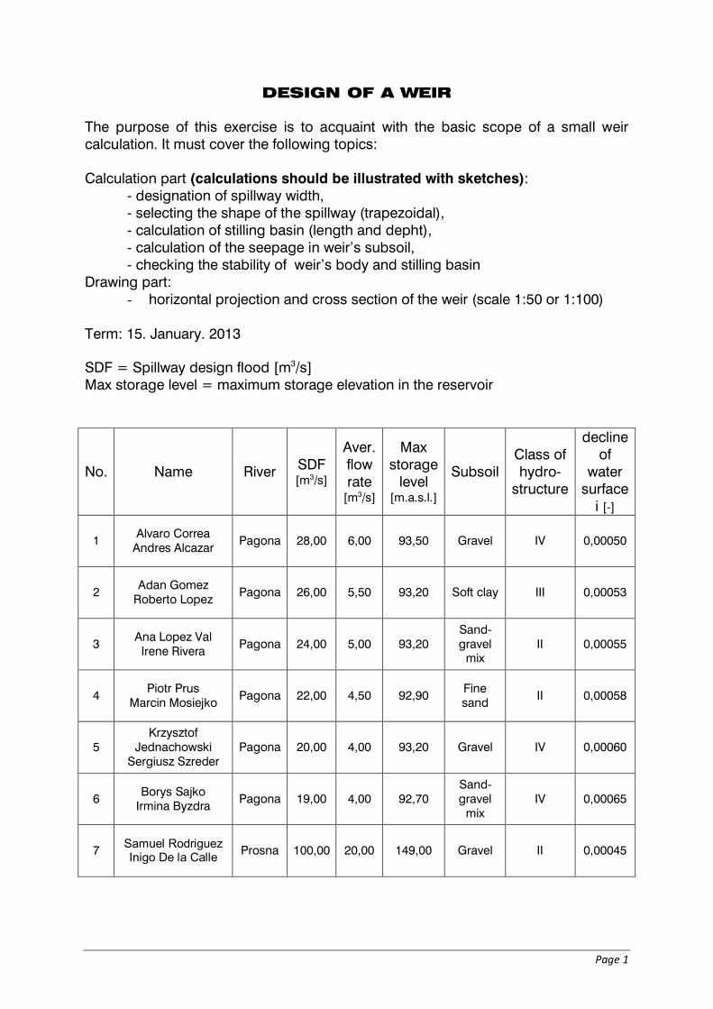
No. Name River SDF [m3/s]
Aver. flow rate
[m3/s]
Max storage
level [m.a.s.l.]
Subsoil Class of hydro-
structure
decline of
water surface
i [-]
8 Aleksandra Latiszewska
Beata Mikołajczuk Prosna 90,00 18,00 149,00 Fine
sand IV 0,00048
9 Mateusz Samociuk
Krzysztof Skrzydłowski
Prosna 85,00 19,00 148,80 Sand-gravel
mix III 0,00050
10 Tomasz Zybała Antoni Żabniak Prosna 80,00 16,00 148,70 Soft clay II 0,00052
11 Piotr Stolarski Maciej Serwin Prosna 75,00 15,00 148,50 Medium
sand III 0,00056
12 Anna Jaczewska Timothy Apiyo Prosna 70,00 14,00 148,40 Coarse
sand IV 0,00045
13 Paweł Stanisławski
Maksymilian Mokrzycki
Prosna 95,00 14,00 148,40 Coarse sand IV 0,00055
14 Karolina Zamiar Wojciech Podleś Pagona 15,00 2,00 92,00 Coarse
sand IV 0,00061
15 Krzysztof Tomczak Maciej Zemfler Pagona 16,00 2,50 92,40
Sand-gravel
mix III 0,0004
16 Przemysław
Wróbel Tomasz Szymczak
Pagona 17,00 3,00 92,80 Fine sand III 0,00045
17 Łukasz Jagalski Remi Mordome Pagona 18,00 3,50 93,00 Gravel IV 0,00050
18 Mohammad Ramadan
Marta Gosz Pagona 19,00 4,00 93,40 Fine
sand III 0,00063
19 Daniel Wrzosek
Marcin Mosakowski
Prosna 100,00 18,00 149,0 Sand- gravel
mix IV 0,0007
20 Jędrzej Sznajder Ilga Navitski Prosna 70,00 20,00 150,0 Fine
sand IV 0,0006
Page 3
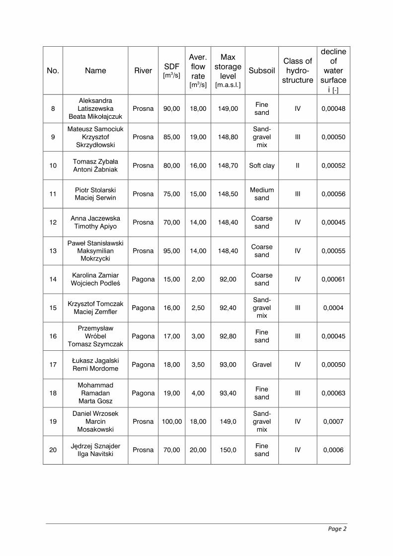
PROSNA river
144.00
146.00
148.00
150.00
0 5 10 15 20 25 30
Valley profile
144.5
145.5
146.5
147.5
148.5
0 50 100
Flow-rate curie (vertical axis: elevation [m a.s.l.]; horizontal axis: flow rate [m3/s])

Page 4
PAGONA river
89.00
91.00
93.00
0 2 4 6 8 10 12 14 16
Valley profile
89.089.590.090.591.091.592.092.5
0 5 10 15 20 25 30 35
Flow-rate curie (vertical axis: elevation [m a.s.l.]; horizontal axis: flow rate [m3/s])
Page 5
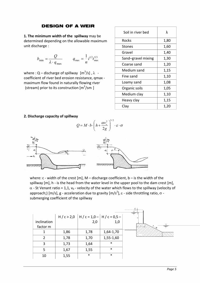
DESIGN OF A WEIR 1. The minimum width of the spillway may be determined depending on the allowable maximum unit discharge::
maxmin q
Qb
35max
21max
1 tin
q
where:: Q – discharge of spillway [[m3/s],, -- coefficient of river bed erosion resistance, qmax - maximum flow found in naturally flowing river ((stream) prior to its construction [m3/sm]] 2. Discharge capacity of spillway
2/32
2gvhbMQ o
where: c - width of the crest [m], M – discharge coefficient, b – is the width of the spillway [m], h - is the head from the water level in the upper pool to the dam crest [m], - St Venant ratio = 1,1, v0 - velocity of the water which flows to the spillway (velocity of approach;) [m/s], g - acceleration due to gravity [m/s2], - side throttling ratio, - submerging coefficient of the spillway
Soil in river bed λ
Rocks 1,80
Stones 1,60
Gravel 1,40
Sand–gravel mixing 1,30
Coarse sand 1,20
Medium sand 1,15
Fine sand 1,10
Loamy sand 1,08
Organic soils 1,05
Medium clay 1,10
Heavy clay 1,15
Clay 1,20
inclination factor m
H / c > 2,0 H / c = 1,0 – 2,0
H / c = 0,5 – 1,0
1 1,86 1,78 1,64-1,70
2 1,78 1,70 1,55-1,60
3 1,73 1,64 *
5 1,67 1,55 *
10 1,55 * *
C 1 : m
H.
v202g
Page 6
2
1h dh
...23
21
oh
q
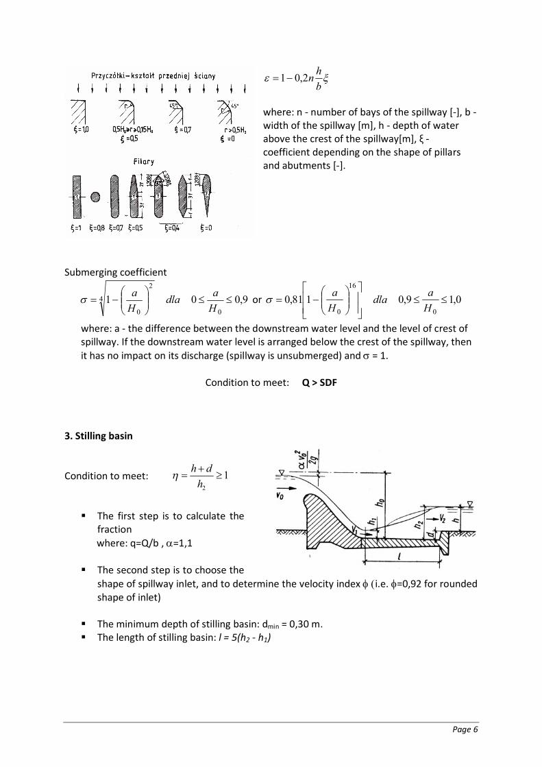
bhn2,01
where: n - number of bays of the spillway [-], b - width of the spillway [m], h - depth of water above the crest of the spillway[m], ξ - coefficient depending on the shape of pillars and abutments [-].
Submerging coefficient
9,0010
4
2
0
Hadla
Ha or 0,19,0181,0
0
16
0
Hadla
Ha
where: a - the difference between the downstream water level and the level of crest of spillway. If the downstream water level is arranged below the crest of the spillway, then it has no impact on its discharge (spillway is unsubmerged) and = 1.
Condition to meet: Q > SDF
3. Stilling basin
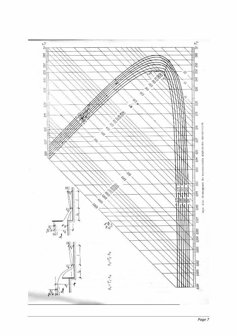
Condition to meet: The first step is to calculate the
fraction where: q=Q/b , =1,1 The second step is to choose the
shape of spillway inlet, and to determine the velocity index i.e.=0,92 for rounded shape of inlet)
The minimum depth of stilling basin: dmin = 0,30 m. The length of stilling basin: l = 5(h2 - h1)
Page 7
Page 8
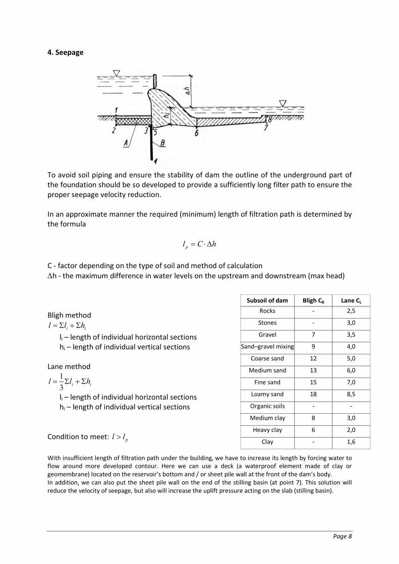
4. Seepage
To avoid soil piping and ensure the stability of dam the outline of the underground part of the foundation should be so developed to provide a sufficiently long filter path to ensure the proper seepage velocity reduction. In an approximate manner the required (minimum) length of filtration path is determined by the formula
hClp C - factor depending on the type of soil and method of calculation h - the maximum difference in water levels on the upstream and downstream (max head) Bligh method
ii hll
li – length of individual horizontal sections hi – length of individual vertical sections
Lane method
ii hll 31
li – length of individual horizontal sections hi – length of individual vertical sections
Condition to meet: pll
With insufficient length of filtration path under the building, we have to increase its length by forcing water to flow around more developed contour. Here we can use a deck (a waterproof element made of clay or geomembrane) located on the reservoir’s bottom and / or sheet pile wall at the front of the dam’s body. In addition, we can also put the sheet pile wall on the end of the stilling basin (at point 7). This solution will reduce the velocity of seepage, but also will increase the uplift pressure acting on the slab (stilling basin).
Subsoil of dam Bligh CB Lane CL
Rocks - 2,5
Stones - 3,0
Gravel 7 3,5
Sand–gravel mixing 9 4,0
Coarse sand 12 5,0
Medium sand 13 6,0
Fine sand 15 7,0
Loamy sand 18 8,5
Organic soils - -
Medium clay 8 3,0
Heavy clay 6 2,0
Clay - 1,6
Page 9
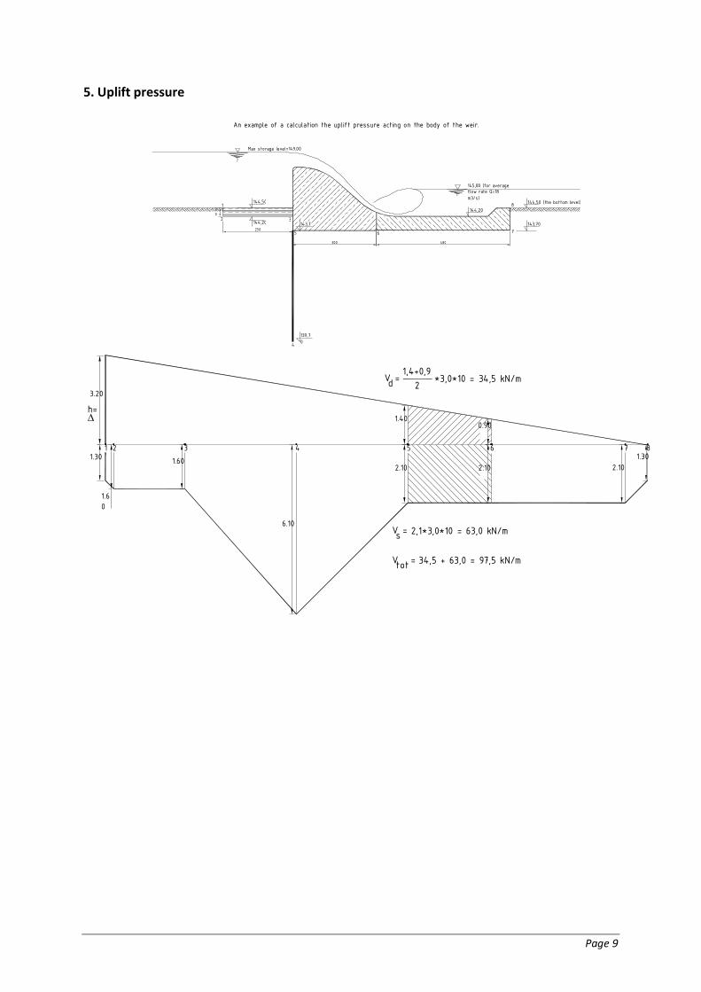
5. Uplift pressure
Max storage level=149,00
145,80 (for average flow rate Q=18 m3/s)
300 480
143,7
144,50 144,50 (the bottom level)
143,70
1 3
7
8
6
4
5
2
139,70
144,2030
1 2 3 4 5 6 7 8
h= 3.20
1.30
1.60
1.60
6.10
2.10 1.30
2.10 2.10
1.40 0.90
250
An example of a calculation the uplift pressure acting on the body of the weir.
144,20
V =1,4+0,9
2 *3,0*10 = 34,5 kN/md
V = 2,1*3,0*10 = 63,0 kN/ms V = 34,5 + 63,0 = 97,5 kN/mtot
Page 10
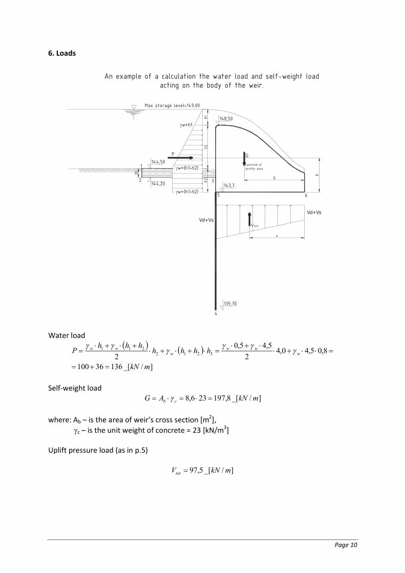
6. Loads
Max storage level=149,00
143,7
144,501
3
6
4
5
2
139,70
30
An example of a calculation the water load and self-weight loadacting on the body of the weir.
144,20
148,50w*h1
h1h2
h3
w*(h1+h2)
w*(h1+h2)
P G
centroid ofprofile area
Vd+Vs
Vd+VsVtot
v
g p
Water load
]/_[13636100
8,05,40,42
5,45,02 3212
211
mkN
hhhhhhh
P www
www
Self-weight load
]/_[8,197236,8 mkNAG cb
where: Ab – is the area of weir’s cross section [m2],
c – is the unit weight of concrete = 23 [kN/m3] Uplift pressure load (as in p.5)
]/_[5,97 mkNVtot
Page 11
7. Stability of the body of dam Overturning stability - relation of the moments of the hypothetical point of rotation (point
n.6 – see the drawing in p.6)
oM
M mVvPp
Ggmo
u
mo Class of hydro structure
I II III IV
The basic layout of loads 1,20 1,15 1,10 1,05
Sliding stability - relation of forces in the foundation
oF
F nP
VGfnp
u
f = tan- friction coefficient between soil and concrete - internal friction angle of the soil no Class of hydro structure
I II III IV
The basic layout of loads 1,20 1,15 1,10 1,05
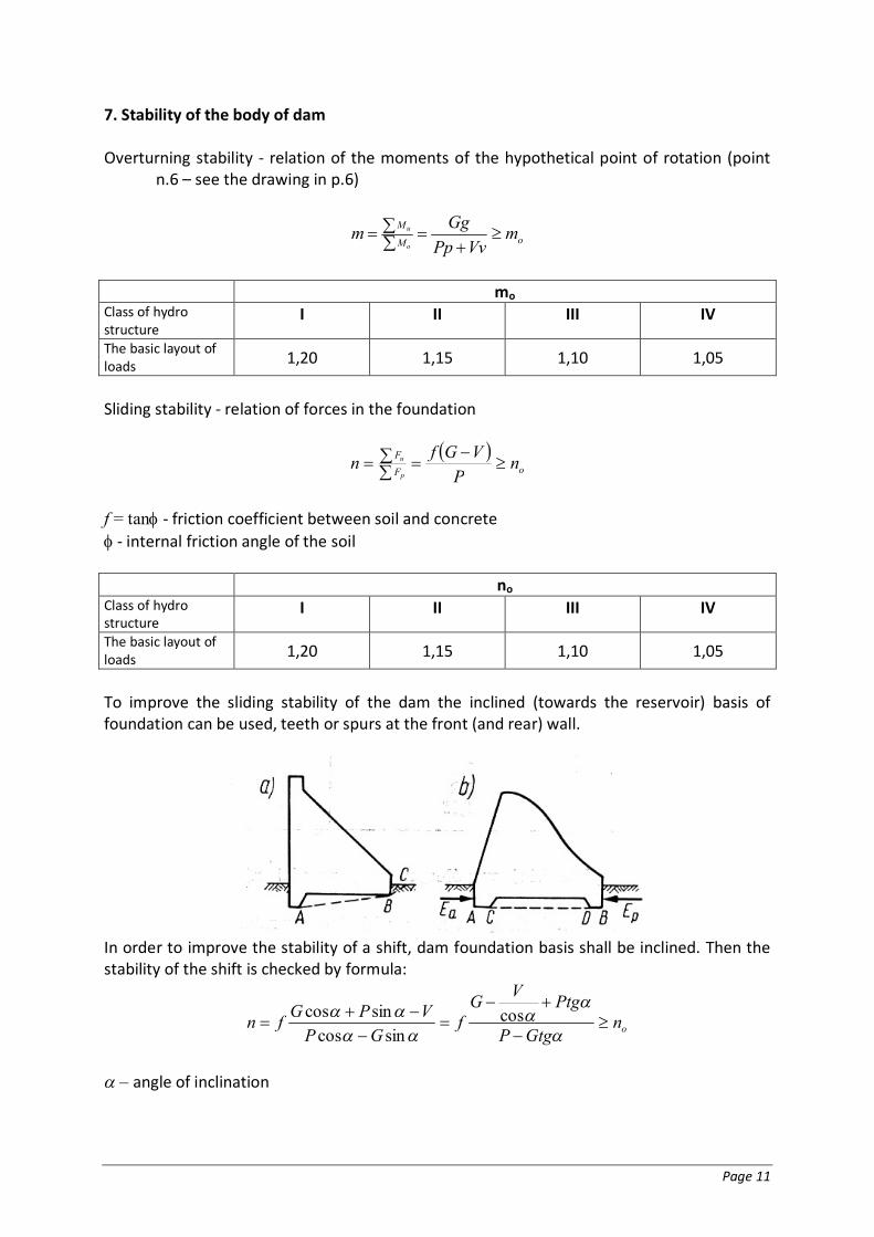
To improve the sliding stability of the dam the inclined (towards the reservoir) basis of foundation can be used, teeth or spurs at the front (and rear) wall.
In order to improve the stability of a shift, dam foundation basis shall be inclined. Then the stability of the shift is checked by formula:
onGtgP
PtgVGf
GPVPGfn
cos
sincossincos
– angle of inclination

Page 12
8. Stability of stilling basin The minimum thickness of stilling basin must meet the condition:
mdhd
w
cn 3,0min__,
1min
where: c – is the unit weight of concrete = 23 [kN/m3] w – is the unit weight of water = 10 [kN/m3] n – safety factor [-] h – maximum value of hydrodynamical pressure acting on the bottom of stilling basin [m]
n Class of hydro structure
I II III IV
The basic layout of loads 1,20 1,15 1,10 1,05


![3 Lecture AxialLoading NoThermal.ppt [Uyumluluk Modu]kisi.deu.edu.tr/ozgur.ozcelik/Mukavemet/Civil_Mechanics_of_Materials/3... · Saint-Venant Prensibi Saint-Venant prensibini (Barre](https://img.pdfslide.net/doc/110x75/5e16716716f7b239d1097c22/3-lecture-axialloading-uyumluluk-modukisideuedutrozgurozcelikmukavemetcivilmechanicsofmaterials3.jpg)