Embed Size (px)
Citation preview

. .,_.,. I C1 4 z.:. ~:J..,~vi;>
UNITED STATES DEPARTMENT OF THE INTE~IOR HAROLD L. ICKES, SecretarY
BUREAU OF MINES R. R. SAYERS, Director
Technical Paper 635
DESIGN OF AIR-BLAST METER AND
CALIBRATING EQUIPMENT
By
A. T. IRELAND
UNITED STATES
GOVERNMENT PRINTING OFFICE
WASHINGTON : 1942
--- -------- --------For 1.ale by the Superintendent of Documents, Washington, D. C.
Price 10 cents
( -1
JJ[-7'1·
www.ARblast.osmre~gov
''"
1(12.937.2169 /lll2.937,3012 [email protected],OV
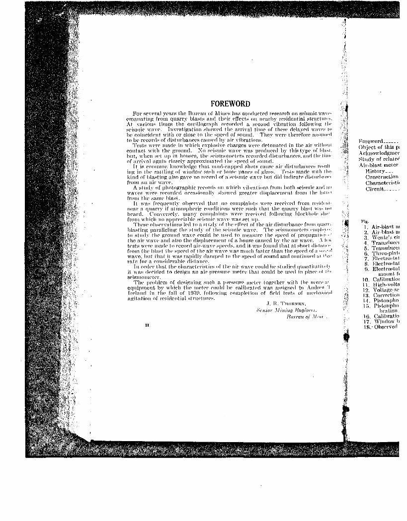
FOREWORD For s('Ycral YcarR the BurC'a\1 nf I\liu(':-< has comlnct<'d research on seismic. wnw·
<'manatillg frn;n quarr_v bla:->t:-: nnd tlwir dft•ct::; on JH'arby rC'sidential st.rur111n-~At nJ.I'iow.: times t.hc osei\Jograph i'PCordcd a s<'cund Yibration followinf! rlw :-:Pismi(' wrtY<'. lllY<'St-iga(·ion ::hmn•d thP arriyuJ timr of thest' rll.'lay<'d waw:< !P lw coincid('nt with nr close to thl' spc('(l of :o;ounc!. They wp_n• thcrf'fon• :~:<:-llliWd f(IIW r<•eorrb of rlishnbn.JH't'S rausNI hY air Yibratinns.
~1\~sf$ W<'l'<' mad{' in ·whirh Pxp\o:-::iy(• charges wert• dC'tonat<'d in t.ll<' air \\·ithnt!l contact- with tlw ground. :\n sPismir wan· was prod.llC'('cl\Jy this type of l•la~.l. hut, \d1cn :>Pt up in house's, t.lw ,..;c•ismolll<'tt'l"H rcrunl<'ddh:turlmllcC's,anrl !lw!ii!P nf arrinl.l again rlosf'ly npproximntPd tlu· -"]Wed of .-::mmd.
It j(': C"cmmJnn \;:nnwlcctp:c that. IHIHI-cnppPd !"hntl' (','lll!"(' air di.-:turbam·c•:-: n·~1111 h1g in tlw !'<tt.tling nf window :::a.-::11 nr lnnsc• p:tl\C'I' of glnR:->. Tc•,.::t.-: mnck 11·ith thl> kind nf h\a.-:ting a.l~n ga.\'<' no n'Pmd of n. ,.:pismiP \\'il\'C' hut dicl indiC"Htl' di.-:tnrl•aw' from :u1 a-ir wan•.
A stncly of phot.ngraphic n•c·nnb em whi('h Yihr~ltinnR from both SC'i.-:mic• ~uu! :111 wnn•s 1n•n• n•c·orckd Cl('{'~l . ..;innnll~ .•dw1n'd !J:l'('fi!Pr (\isplac<'HI<'Ht from tlw !:111•' froB\ tlw :-::um· hln:;t.
It \l'fl:; fr('ql!('ntly oh.~<'l'YPcl that no complnint:-: Wl'H' rec<•in•d from l'l'~id1 HI·
JH~Ill' a quarry if n.tmnsph('ric PmHlition::; IYC]'(' Rueh that thP quarry bln:-:1 mL~ Jud
!ward. Conn·r~<'ly, many complaints wC'n' l'P{'c'iYP<l follm\'ing hlockhnlc· ... ]1"' from which no nppn•cinh\(• :-:c·i:-:miP ,,-n,·c· w:-u: >:<'1 11p.
Tht'8(' ob.-::{'rYnl ion:-: l0cl ton f':llld,Y c1f tlw I'll' Pel of tlw air distm·haHCI' front qu:trr·, hla:-:ting parnlleling liH' :'<!ncly of the spi,.;mie wan•. Th{' :-:<'iRmonH•tc•r:-: t'lliJil".''' t.o R\JHly thC' grmtnd waYC' <'011\dlw ll~t·d to measnn• tlw :-:pt'<'d of propagalic•l' · · the air wnn· a.nd nl:-o t-he di:-:placPlll<'llt of n holl~C can~ed by tlw n.ir Wl).Ye. .\It 11 t.<'Sb'l w<·n' mad I' to rcconl air-wn.YI' :-:pPPds. and it; wa::-: found that n.t :-:hor-1 di:-:1 :l!w•· fmm t.lw bln:-:t tlH' .-:pePc\ 0f 1lw nir Wll\'P '\'llf': much faster than th<' SJWI'ci of a~,.,,,_.! wave, lmi that it wn.t:: rapid\~· dnnqwrl tn tl}{' Rpe<·rl of ROnnel am\ eon\illllf'd al 11•:•'
rntc for a <'OJt:-:iclPrahl<• di:-:1 lllH'<'. Tn orfi<'T t-hai tlw r.lwraetc•ri.-:t ies nf tlw a.ir wn.-.,e could h<' Rindi('{\ qww1 i1a1 i1 ··!.1
it. was r\c>cidt•d to (\('sign n.n air-pT<'f':Siln' nlC't<'r t.hnt conic\ h(' n~r·rl in pl:H·c· ol II•• Sf'iSillOllll' I ('J'.
Tlw problC"m 0f designing :'1-neh a pr·<•ss.nr<' nH'\N tog('t.h£>r with lh<' Jlt'tT." ;P cq11ipn1<.mt. h~' which th<' m<'tN' rnnlcl hC' cn.libmtc·d \Yas a.s.o:ignNl to Ancln·11 'I fr·t'hlnd in t.lH' fall of 103\1. fnllnwi11g <·nmplP\ion of fi<'ld h~f':h-; of 1\H't'll:r••i,·:•! ngitnl'ion of rP~idt'ntinl s1nw1m<'.-:.
.T. H. 'l'noE:'>lE~. Srnwr _,finin(l Un(li1u·r·1.
Hurrau o_( .ll•m
II
Foreword _____ _ ( )hj{'Ct of this p: Acknowlcdgmer St.ndy of rPla.t.f'i Air-blast meter
Hist.ory __ _ Construction Characteri:-:tic Circuit __ ----
Fig. 1. Air-blaRt m 2. Air-hlaRt· ll1 3. \Y cntc1
R ciT 4. Transduct'l 5. Tra.nsrlttrl'l 6. Thrcc-pla\c 7. ];;Iect.roc--t.rr I 8. Elect.rn~tal H. Electro:4a1
mount. fc 10. Calibrn.tim 11. Iligh-voltn 12. V r;ltagc-Rc 13. Correct.ion 1-1. Pi:-;tonpho I il. Pistonphn
hrnUon_ 1 (). Calibratio 17. Window b 18. · Obs<'rved
S£'i:-:mic w:rn•-. in! ~t-l'll<'llm·:followiu~ I h•: \\"('tl \\'ll\'t':- ,,,
t;fOI'I' ns~\llllt'' I
lw nir wil ho111 lypi• of l•Jn,.l,
"-,:\IUII\\1•(11111"
'h:IJU'I'S \'t':->1!11
nndt• wi1l1 thir. II' tlislltl'l•ntll'l'
·t'i.t'l\\k llllil tlil
··om tlw \all•·J
from n•:-it\1'111· 1•\nsl '' u:-_11•>1
ltH'klu•lt- ;.fH•t-.
t't' from ij\11\JT_\'
'11'\'.t' t'lll!Jh•,\t'tl ]ll'ilpH~tHIJI\11 nl
\\'ll\'t~. .\ ft'\\ ..;Juu·t distn•n·•Jt'Pd of /li'<OI\Ih\
J\.ill114'd !\I lli111
·JIUUJiiln!J\-t'h
in pint·,- .. r ''"
I he• lll'l'l'h"ltt \
to Andl'n\· 'J'. nf mc·c•lmuh'ltl
I•:N,
'uaiurn. 1111 of .llt11n-
CONTENTS
Page Foreword ____________________ _
Obj£'ct- of this pap£'1' __ _ :\cknmYledp;mcnt~-- __ ~tudy of related phcnonH'na ___ _ Air-blast. meter
History--_ Const.ruct.ion _____ . _________ _
n Electrostatic actuator _________ _ 1 Theory ___________________ _ 1 ConBt.niCtion _______________ _
1 Tm~t:;: __________ ------------
2 Pistonphone _________________ _
2 Theory ___________________ _
3 ConstructiOn _______________ _
4[ R;;~~·:or 1;rCltmil~a-n; fi~ld t-~f£s~ 5 Bibliography _________________ _ Cha.ract.eri;-:tics _____________ _ Circuit ____________________ _
ILJ,\iHTHATJ0:\8 Fig. 1. Air-blast meter________ ·---··-- -------------- --------2. Aic-bl"'t mete'---------------------·--- ------- ----3. \Vente's eircuit_ ____ . ______ ------ ________ _
, . 4. TransdncN circuit __________________________ - .. ----------------'·- J 5.' Transducer hox, shiclcicrl cable, and air-nwtcr asRcmhly ____________ _
~;.· 6. Thrce-pln.tc condenser__ _ ______ _
7. Elcct.rost.atie act.natnr ____ - _- __ -- __ - . -~ 8. 1.-:lcctro:::t.atic-actuatm· voltage supply_
9. Electrostatic actuator ·with air-hla.st mPtN and spacing \\·asher ready to mount. for calibration________ _ __________ _
10. Calibration of the clcct.rostat.icacttmtor____ -------------------11. High-voltagC' rectificL------------ _ -------------12. Voltage-Reparation graph and electrof'tnt.ie actuator _______________ _
i 13. CorrC'c-tion curve for pistonphone ____ _ '' 1·1. Pifltnnphone assembly _____________ .. ~ lfi. PistonphonC' wit.h air-blast meter and microscope mounted for cali-
brn.t.ion_______ -----------· 16. Calibration of 11istonphone ___ -- _ 17. \Vindow box ______ .. 18.· Observed pressure-distance relationship.
III
Page 6 6 9
11 13 13 14 16 17 19
3 4 5 6 7 8
10 10
11 11 12 12 14 15
16 17 lR 1R
"'
I
DESIGN OF AIR-BLAST METER AND CALIBRATING EQUIPMENT 1
OBJECT OF THIS PAPER
The objeet of this paper is to describe the evolution of the design of n.n n.ir-blnst nrPter to be used for measuring n.ir pressun's from quarry hlnsts and the design and n.pplieation of equipnwnt required fo·r en.librn tion thereof.
ACKNOWLEDGMENTS
The u.ut.hor wishes to acknowledge his indebtedness to J. R. Tluwnen, ~uprrvlsing p.ngiiH'Pr, Nonrnetnl ~'lining Section, for his direction of the work, eonstructivr critieism of the manuscript, and helpful suggestions; to Stephrn L. \Vindes, seisrnologie obsrrver, NonnwtnJ ).lining Sl'ction, for his valuable a.dvice n.nd aid; to Jack T. Donovan, junior physical sc.irnc.P- aid, N omnetnl fihning Section, for his assistj
' nnce- in enlibrnJion; and to Rudolf 1\.:udlich, superintendent, En.stcrn E:xp{':rimrnt. St.ation, C. 1vl. Davis, n,nd l\L R. Priee for construction of t.Iw nppnrn.tus.
STUDY OF RELATED PHENOMENA
The fact that the hig-h-pressure impulse of an explosion has a higher dPnsit.y a.nd lndrx of refraction tlmn the undisturbed air is utilized in t\\'O methods of photogmphing (21, 22, 23, 25) 3 air waves from <'Xplosions. The Schlieren method (34, p. 342), by an ingenious
- ;UTn.ngPrneHt. of Iens<'S n,nd mirrors, photographs the- wave by means of its chn.nging indpx of rdrn.etion and density. The shn.dow method
· of Dvorak (34 1 p. 340) photographs the shadow of the highly compressed p1·essurc wa.ve. \~Tith either n1ethod, a spark mn.y be used ns the source of illurnination for an instantaneous picture, or an arc nnrl a moving film may br used to givr a continuous record of the progress of the wn.ve. By plotting the position of the wave against tirne, the veloc.ity of the wave nt any distn.nce from the source may lw determined. HowPvrr, ncit.lH'r rurthod direet.Iy mrnsures the pressure or enngy of the wave. Both methods are dr.signrd for tlw study of the shape m1d speed of high-pressure. waves at short distane<•s from a small explosion, and neither could be adapted easily to det.or-
~ mination of lower prrssures at greater diStn.nces from the sourcP. ·: Explosions in eannon and engine eylinders also hn.ve been rccordt>rl ~by vu.rious typPs of gages (15, 16, 17, 18, 19). Sueh gages have- a high
1 Work on mnnlls{'ript comp\{'tcd March 20, 1941. ! Junior physicist, NonmC'tRI Mining Sertion, Mining Division, Httrcan or l\-rili('S.
. a Nnmbt'fS in pnr!'nt.h('scs refer. to rcreren<X's In the bibliography; page nmnbrrs are t.hose In the refHences ··:.and not in this publication. l
•··.
·"
2 AIR-BLAST METER Ai\D CALIBRATING EQlliPl\lENT
natura-l frequency so as to rrspond to the. extn'mrly rapid risr in pressure for thrse confined explosions n.nd n1ust be constructed rigidlv to withstand the high prrssures. Thrrr nre three p:eneral typ<'S Or these gages-the piPzocleet.ric, rrsista.nee, nnd condens<'r. In tlw piP?.ne]er.t.ric t.ype the prrssure eauses eomprrssion of n sLaek of piezoPlrrtric crystals, the resulting voltngo bring mnplifiod and recorder! by suitn hk mPans. In t.lH' resistance typr, the- pressure eanses compression of n carbon pile wit.h a resulting change in dect-rien-l resistance whi<·h is reeorded ns a pn'ssurr-timc relationship. In thr condenser gn.p:<' th(' pressure bPlHls n. din.phrn.gm of high na.turnl fn•qn<•ney toward n rigid plntP, and tllt' resulting ehn.nge in p](•.ctrir.nl cnpneit.a.ner. giYes tht• prrssnrC'-timr rela.tionship. Oln~iously these gngrs nre drsigned tn mpn.sure pressures far nbove those rrquirrd to dmnn.gf'. a building-.
On tlH' other hand, the vnrimiR typrs of 1nierophones in common USC' 'iYC'l'f' de.signe<l for sound Pnuuw ting from surh sourres as Yoitw. tnnsi('.a.l instnnnents, trn.ffie, etc., n.ll of whirh, ns shown by common rxprrienrP, n.rr harmless t.o buildings. It wns llf'rt':::sn.ry, therefore, to design and cnlibrn.te an instrument for the nwasurrnwnt of pressurps rn.nging smnewlwre het.vn'Pn these extrc1nes.
li..,rom l'l<mwntn.ry prineiplrs of mechn.nics, it c.an lw stated that. a.ny dn.InagP dmw to a building by the n.ir blast will dPp<'lHl on the construction and condition of the building itsPlf ns WPll as upon tht· size, distrHmt.ion, and duration of forcrs acting upon thr strurtnn•. Thes<' fon:f's n.tr any mmuent ean bP computPd most. {'asily. from n timc-pressurererord. 1.'hey could also bt~ comput.Pd from the VPlocit.y. or mnp1itudP and frequency, of motion of t.Jw air particles, hut sn<'h n. emnputat.ion would require tha.t thf': vPlocity, or amplitud<' a.nd frequency, be used to solve for thP prrssurP, whir.h would tlwn he integrated over the area nffeetrd to give Lllf' totn.l fore<'. Rcgardh•" of the method used, it would bP dif!ieult to eulculat ... exact!)· (.\1(• minin1mn force 1wcessary to damage a C{~rt.ain building, but it. wu~ thought that this difficulty could br OV('rromp by uutking ohsNYHt.ions upon a. number of buildingH and dPt.t•nnining a limit hPimr whicll. an ordinary structure would not be dn.mn.~ycl.
To make these observat-ions it wn.s nPc.Pssa.ry to d<•sign an instrunlent that would nwasure pressure cha.ng('S, and it "~as desired t.luH it should have linear frf'queney and pressure rpsponsP ovP.r any nntiripat,ed range. Further, it shm1ld have different sl'nsitivity rangt• ..... n.nd should be rugged t•nough to minimizP Uw rlanger of bP.ing dn.mu~~·d or thrown out of adjustnlPnt in thP field. The amplifying n.nd r(•.ronling equipment should not hP unduly con1plir.atcd or require cxr('f::~irr· power fCir field use. l\1PasurPment.s should be reproducible, should be in absoJute units1 and should be accurate t,o within 10 prr<'t•nt Although the. desirability of prrcision nwasuremPnts was rt•ali:•wd. i1 was felt that, owing to the grt>nt diff<'n•nrPs in tlw construction :1nd eondition of buildings, the addrd cost. Ilf'ct•ssary for pr<'ris<'. Ifl('fi.Slll'!'
monts would not be justified.
AIR-BLAST METER
HISTORY
Of the prrssurc-response instrnnwnts in common use, t.h(~ rondPII~(·rand crystn.l-typr microphones giye thr. n1ost nearly linear f.n•.qut>IH".\' I"Cspons<' below their resonant frf'.q tu•nc.ies. The condrnsPr micro- ..
phone (set' fig. 1) was easily eonstructcd an condit.ions.
E. C. Wente's cond< ist.ic that its scnsitivi que-ney range. It co of a rigid pluto.. Th diaphrn.gn1 and IS srp em. (0.001 inch). Tl in t.lw plato and holes bPhind t.lw plato. Tl bv a srnrill hole or by fOr c.hangrs of atnlOSf dia.phrngm and pla;t.r at hight•r frPCJlH'llCH'S
the natural frcquenc 1nicrophonc can be 1 a few hundred eye!< frequency of the dia]
As the n.ir-blasl m and the n1ete.r reasst stretched 1nen1bntn~: son1e loss of sensitiv of the same resomtn1
disadvnntn.ge. . . . Diffcrrnt sens1t1vi
thickness (0.01 ±em spacing between the chosen for the diaph ~lnsticity insure hi; Other metal parts distortion due to t clamped portion oft frcquoney of the tln

,jd rise.• in l·l'<·.l l'igitll\' I ty}H'S t;f · Uu•.pi<•?.o( •ztwlf't' I rie \Y suitnhl" •ssir)·n of n •' \Yhidt j~ r ghg-t\ I ht• ll'd n ri~~id ~jyp~ ~It'
•signed to niildiJ.lg. 1 rommon
..; ns voi('.P, \" ('.OJlllHOII
Prpfon\ t.o ( pt'PS~iJI'P~
I thnt. unv 1 l.ht' cmlnpon t.hP st.rul'l-11 n·.
1h· frotH n <; vl'lo<'it.y, . hut. su;·b ~it.tidt' :mel d Llwn he• l{t\gitJ•dlt·:4~ xnt·.t.l\· tlw HIt it ,.;~11 :-: ~ ob.•-wn·nlllit. lwlow
n.n inst.r·u•sircd t.lutl nny nnl i('· i t.y' riut~t·H
\T dn.mntrt>d ~ul rP.Pc~·~ I ·' exc·Pssivt· 1le, should 0 P<·n·t·ut. I'PU.lizPd, it <~<·t.ion und • llll'll~lll't'··
t'01Ult'll:4t'l'
frt•q IH_'IH'_Y St'l' lllH'I'Il-
AlR-BLAST :METER 3
phone (see fig. 1) was chosl'n instead of tho crystal type because it is t•asily constructed and its response is independent of atmospheric conditions.
E. C. Wente's condenser microphone (13) has the notable characteristic that its sensitivity is comparatively constant over a wide frequency range. It consist.s of a steel diaphrag1n stretched in front of a rigid plat.e. The plate does not conr the entire area of the diaplu·u.gm and is separated from it by "'n "'ir space of about 0.0025 em. (0.001 inch). This air space is connected by grooves "'nd holes in the pla.t.l' and holes at the side of the plate to a larger air chamber bl'l1ind tlw pla.te. The large aiT chamber is connected to tho outside by u. small hole or by 111cans of a componsating diaphragm to allow for changC's of atinosphcric pressurE'. The thin air space between the din.phrng-n1 and plnk OYPnlmnps th<' din.phra.gin at low frequencies; at hig-lwr fl'f'C{1H'neiPs it n,d<ls stiffness to thC' diaphrri.gm and rais($
FH!GR~ 1.-Air-hlu:>J mct('r.
the natural frequency of the system. The pressure response of the microphone can be held comparatively constu.nt from frequencies of a few hundred cycles per second to frequencies above tho natural frequency of the diaphragm.
CONSTRUCTION
As the air-blast metoT must be t"'kcn apaTt, the sensitivity changed, and the meter reassembled in the fielcl, a clamped plate instead of a stretched membrane wa.s used as the diaphragm. This resulted in smne loss of sensitivity, as a plate is less sensitive than a mmnbrane of the same resonant frequency; but this \vas not considered a serious clisadvuntage.
Different sensitivities are obtained by using diaplu·agms of different thickness (0.01 ±em., 0.03±cm., and 0.05 ±em.) and by vaTying the spacing between the plate and diaphragm (fig. 2). Duraluminum was chosen for the diaphragm because its low density and high modulus of elasticity insure high sensitivity for a given resonant frequency. Other metal parts ulso were made of dumluminum to avoid any rlistortion due to temperature changes. The dimneter of the unclamped portion of the diaphragm is 2.5 em. (1 inch), and the resonant
• frequency of the thinnest diaphragm is about 1,400 cycles per second,
·•
4 AIR-BLA~'l' ME'fER AND CALIBRA'.riNG EQUIPMENT
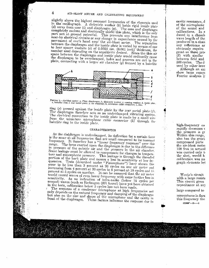
slight.ly above the highest rf'sonant frequencirs of the dements nsPd in the oscillogra.ph. A dil'lretric washer (b) holds rigid inside plat<' (d) amty from case (i) a.Jl(l diaphragm (a). The case :md diaphrngm completely enelose and electriea.l!y shidd this pln.te, which is the only part not n.t gronnd pot.C'Htinl. This prevents any interference from ncar-by electrira1 rireuits or nny ehnnge in ea.pneitane-e en used by thl' rnove1nent of one's hnnd near the nir-blnst. mc•ter. The separn.tio11 between the diaphragm and tJH• inside p1n.tr is va.riecl by nu'alls of on1• to four spacer washers (c) of 0.0025 em. (0.001 inch) thickness, t.llf' number used depending on the sensitivity drsirrd. Since the thin nir spn.ee between the diaphrngn1 and insidr plntr wonld ordinarily cn.mH' the din.phragm to be ovrrdn.mpNl, holrs and grooves are cut in t.l11• plate, connecting wit-h a lnrgor air chamber (g) formed by a bu.kelit<'
" • ~-b
~-=-=; ~;,>1--g =--i
FIOt:RE 2.-Air~blast m('ter: u, Plnt.t• diaphrngm; IJ, dielectric wa~her; r, ~pncing wnshcr; d, insi(k plat<-. r., bakL•Iit(' rin~; f. rrar metal pl11tc: {1. 11ir ehnmber; h, minint.un• L'!lblc eonncctnr; i, rase. <t
ring: (e) pressed ng-n.inst the inside. plate by the renr metal pblc (fl. The dinphrn.g1n lhrrt'fore n.ets ns nn l.mdC'nln.nlpNl vibrn.ting- systrm. Tlw p}ectrica1 eonneet.ion to tlw insidr plntr is mndr. by n. small wirt• from thr minitl tm·1· mierophonp en hlP c.onne.etor (h) through I he· bn.kditr ring to the inside• plntP.
OHARA CTERISTICS
As t.lw diffphrn.gm is undrnln.rnped, its dcfleetion for a certain forC'r is the same n.t. nll frrqnew·iPs that a.re sn1n.l1 eompnre.d to its rcsomu11 frequency. It therrforr has a. "linear frequency response" ovN 1-hi~ range. The force e.xprtrcl npon the din.plnn.g1n is chH' to t-he clifYrrC'JH'I' in pressure of the ontsidr air n.nd tl1e prrssure in the air ehmnlH'r. Some leakage must he a.llowt'd to rom}wnsa t.e for ('luwges in t.rmp<•rntun• and n.tmosphrric JH'rssm·P. This len.knge is t.hrough the t.hn•ndl'd portion of the bnck pln.tc nnd c.n.uses n loss in sensitivit.y nf. low fn·quencies. 'l'0sts (dr-scribed under uPistonphmw") · hn.vp show11 fhi~ error to be less thn.n 2 prrcent. n.t 20 cydes on one n.ir metl'l' aHd incrensing from 4 pereent at 20 cyc.lcs to 8 por~ent a.t 10 cyrl0s and I;, percrnt at. 5 cycles on another. It cn.n be n..ssumrd that t.lw nir nwtl'r would rreord wn.yrs of rven lm,~rr frrqnr:ney with somr furthrr loss in sensit-iYity. As no indirnt.ion of infrn.-n.udio (below 15 cyclrs JWr seeond) waves (such n.s 1Gs£'hmgon (20) found) have yet bern ohLflilH'd in the tests, ca.librn.tion brlow 5 eyeles hns not. bern made.
The response. of n. conclenspr n1ierophone at high frequenci£'s uo1 only drpends on the nn.turn.l frrquency and damping of the dinphrng-n1 but n.Jso on the size n.nd shape. of the mierophonr n.nd the cavil.y in front of the diaphm.g:m. Thcsr factors influence the response dnr to
-.l
..
ca vi tv resonance, d of the mierophone of the sound u.nd calibrn lions. In o ducrd in a chamb wn.vr leng:th of the produced in a chan any rPficctions aT ob;•iously require o-rca t as those prot (2) with similar between field and 500 eyelcs. The d· usrd ·bv other inve
Altlioup;h an ex] show lnrge romp< Fourier analysis (i
high-frequency co rapidly decrea~scs ,. the pressure IS g1
\.Vi thin this runge, also has the great· compressed pa.rts the air-blast mete1 100 fret to several was carried only t• the shot, would h calibration was no graph el!'mcnts bci
W cntc's eircuit with a. large resistl This eireuit. gives capn.citancc at an~
large compared to
microphone in fara this frequency the
423668°-42-2
(
G EQlilPI\.fENT
pg of thP rknwn Is URt>cl
holds rigid insid1• pb tc• l,he r-nsp nnd <lin phr:J~nl pln.te. whieh is tlw nnh
" nny int<•J'fP.retH'P fro1;1 pneitnner <'n.nsl'd bv tl11'
met~r. ThC' sPpnr;t t ic1r1 Yfll'If'd by HH'U.US of Oil I'
101 inch) t.hir.kn<'RR, 1 ht• I'Pd. SincC' tlw I hin nir would ordinnrih· <'n u:-;1' grooYrs m·e eu{ in 1 he·
!) fonfwd by n. hnkc•litc•
Q
~""'~~-! ~1----g """OJ<--i
<', ~pnrini wnslwr; rl, in:;id<· I'IHI• •It• roUTJt•rtnr; i, '('R~'C.
a• n•nr 1netnl plnt1• t (1. nJwd vibrn,ting sn.;h,-111. : mnde bv n ~;un'll wirt· •ctor (h). throug-h !Itt•
tio·n for n crrt.ain fnrl'l' mfmrrct to its rp~onnnl cy rpsponsP11 O\'PI' 1 his is dur lo Uu• difl'l'l'I'JH'f' ·p in the n.ir c.hmnlH'I'. 1r e1umgrs in II'IIIJWI'H·
; through llw t hrt•Hth·d spnsit.ivit.v nt low fn· nrn) · hn-v~· shown I In~ ·Hl one nir mPIPJ' nnd ·ntnt. 10 ey<"lc~ nnd lh nrd that t-il<' nir nwl,·t h smnr furt hPr loss i 11 (below 15 c.yciPs Jh'r nn~ Yt't. been ohlnitwd lPPn 'made. hip:h fl'<-'(]l.IPIH'i<•S 1101
ping of thP din.phrng111 llll' rmd thr envily i11
r t.hc rcsponsr du·~· to
AIR~ BLAST ME'l'ER 5
cavity rrsonnnce, directivity, n.ncl diffraction (2, 4, 5), as the clinu•nsions of the microphone become an appreciable fmction of the wave length of the sound and usufl.1ly neressitn.te sepn.rn.te field and laborn.t.ory en-libra tions. In a. ln.boratory calihrution1 the sound waves n.re produced in a ehmnber tlmt is rclath·ely small when compared to the wnsr length of the sound. In n. field ea.libration the sound wrrvrs n.rr producr(f in a chamber so lar~e, or with wn.lls so sound-absorbent, thn.t. any rdlections are negligibLe cmnpnred to the som·re. It. would obvious!)' require grrrtt power to produce sounds with pressurE's as gren.t. ns those produerd by pxplosions. The investigations of othrrs (2) with sin1i1n.r condenser microphmws showed close agn•rmPnt. hetweP11 firld and laboratory r.alibrat.ion n.ncl negligible errors up to 500 evcles. The dimensions of the mrtor were mn,de snmllcr tlmn those usrd Lb~,. other investigators to aYoirl the nccr.ssity o.f field calibration.
Althongh an oxplosion has a very steep wave front, whieh "~auld shmv lnrg(' romponrnts of high-fr0qurnry 1vn.vos if snhjrrtNl to Fourier analysis ($4, p. 27), thr. dampin~: is so murh greater on the
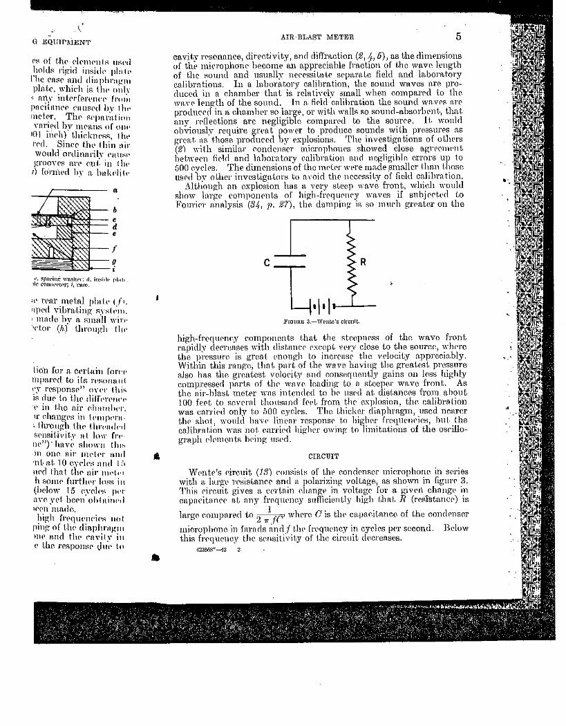
FIGURE 3.-Wente's circuit.
high-frcqupnr.y cmnponcnts t.hnt the strepnr.ss of the wave front rapidly derT(\flses with dist.nncP px:eept. VC'ry close to tlw sourco, w]wre the pressnn~ is great enough to incrrnsr the vrlocity approeia.bly. Within this rnngc, that part of t.hr wnve having the greatest pressure a.]so has the greatest velocity and consequently ga-ins on less highly cmnpressed parts of the wave lending to n st.ccpcr wave front. As the air-blast n1r.tr.r wns intended to lw US(~d at. distn.Jlcrs from about 100 fept. to scY('l'Hl thous:md frPt from the explosion) thr. calibration was cnrri('(l only to ;)00 cyelrs. The thicker dinphrn.gm 1 used nearer the shot, wmtld hnv<• linear TcsponS(' t.o higher fn~qurnri<~s, hut the cnli.bTntion wns not. enrri('(l higlwr owing· to lirnittLtions of the oscillograph p}pmcnts hPing usPd.
CIRCUIT
VVPntr's r.ireuit (13) ronf'lists of tlw condrnser mierophone in sr.ries with n. lnrge rPsistanrr and n polarizing voltage, n.s shown in fignr<• 3. This rircuit gives n. ePTt.ain ehnngP in voltnge for a. givri\ change in cnpnritnnrP n.t any freqw•ney sufficiently high tlwL R (rcSistancr) is
lm·gr. eompm·p.d to 2 'lrl rr' wlwre cis tlw cn.pac.it.a.nce of the conch•nser
microphone in farads fln(l.f t.lw frrqurncy in cycles pt>r second. Below this frPC}lH•ncy the- S<~nsitivity of the circuit decreases.
4236f>8°-42-2
..
"
.-\lR-BL:\:-<1' .\lETEH AXD CALIHHATlKG EQl'lPl\IEI\'T
Tlw disndYnntngt'S of t.hi::: S!TSt<'m for low frc~qnrnril's nn· obvious. l\lm·pon'l', tJw first. stng:P of thr nmplifiPr usnnll~v is kt•JH- rlose to t.hl' microphmw to nvoid adding rnpnrit:mcP in pnrnlld ·with the mierophonP :llld d<'<'r<•nsing tlw srnsitiYity. li'or high-pn•ssm·1' work this would l'XflOSI' the nmplifiPr to SPYl'l'P shocks. FurtlwrmorP, this rirruit n•quirPs SPYl'rn1 sl-ngi'S of :nnplifirntion, whir.h nrc difllrnlt t.o cnlibrntP nnd mni11tnin in <'tllibrntion.
A ,lightly mo<iifi,,<i form of the trnnsdurcr rireuit (26) used b)' tlw Burpnu of ~Iinc•s in its seismic. rPSI'nrcli "·ork "-ns ndapt.P.d in tlw form sbowu in figun• 4- mHl giYes linPtlT frN[liPllry rPsponsP from stntic to
31 31
Cj
1· io
B
R, To air-blast meter
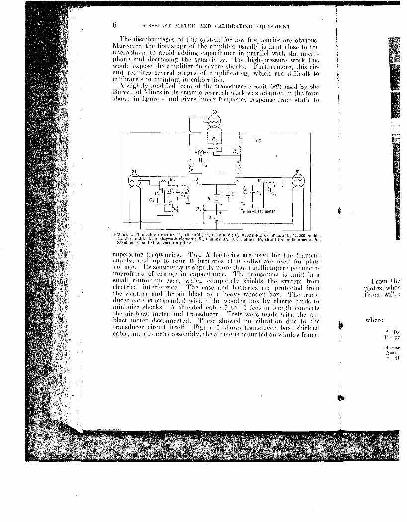
Fh:nn: I. ·Trnnsdtu·l'r dn·tut: C.·, lUll mftl.; C1. Htl) mmf>!.: c~. ll.lltl2mfd.; Cl, -'•ll nnuft\.; (~, :mu mmftl.: C;, 200 nnnfd.; 0, o~eillu_crnph Pil'ltlt•nt; Ut, G olnn~; R~. ;;u,ono ohms; Ho, shnnl lor mHlimnmetcr; R1, .'iOO olllns; ;l!l Mid 31 iln' Y:lC'lll\111 1 nhPK
stl})('l'sonie frN[IIPIICi<•s. Two A l)nHI'l'i<'S nn· mwd for tlw filanwnt. Rllppl!r, nnd up lo Jour B hnttl'riPs (lXO rolts) fl1'<' \IS('(] for plnl1• YoltngP. Its srnsit jyjty is slightbr morp tlullJ 1 millinm}WJ'P pPr mirromirrnfnrad of dwngP in rnpnc•itnnr<'. Tlw trnnsd1wer is built i11 :l
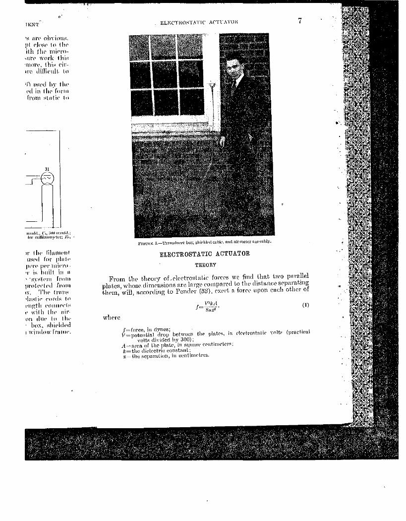
smnll aluminum ('llsP, whieh <'ompldl'ly shil'lds tlw s_vst-Pm froJll Pl('ctri<"nl inll'l'fl'l'('JH'<~. Thr cnsr n1Hl batlPri<•.s nn• prnkrt.rd from llw WPatlH•r mul t.]w nir h1nst by n lwnYY wood<'ll box. Th<' 1Tfl-llS-1hH·<'I' cnsl' is suspi'IHINI within 'tlw woo1lL'll box by Plustic cords to minimizl' shocks. A shiPltlNI cnhlt• {i t.o 10 fPC't- in lPngth COlllH'.r1s t.lw nit·-blnst nwtpr nnG trnnsdtH'PT. TPst.s -..n•rr lll:Hk with thr nil'hlnst llH'II'r disrmmC'rt.rd. ThPR<' shm\-Pd no vihrntinn dlll' to ilH' l-rnl!sd!H'I'l' <'ireuit it~wlf. Fig-urt' 5 shm\-s tr~msdurPr box, shirld1~d enbl<·, nnd nir-lllt'tPr HSsPmhly; tht• nir nwter mountNl on wiudo\\-frnnw.
..
• II
I I
From the pln.t-es, whm llll'm, \Vill, :
wlwre
A.=ar k=tlx=t.l
lJGN'l'
·s Ill'<' ohYiou~. pt elo:w to tlw ith ilu• micro
..;m·t• work 1hi~ llHH'<', thi~ ('ir-· 1re diflicult. to
I!') t1RPd lJy t Ju• I'd in tht,'forln from ~t11tic It)
31
~
lll!H[ol.; c,, ;;nu lllllllol.; fur millhmm!•'h'l"t Ji,,
ll' 11H' lil:lllll'lll
UHI'd for plul'· ppn• JH'T mit•ru ·r i~ huilt in 11
''RYf'1t'lll frnlll
pro.l<•t'IPd frfJIII
IX. Tht• t I'll !I~ •ln:-:1 ic ('OI'd~ In t'IW,:1h ('()Jlfll't'l:-<
I' ~Yilh lht• nit·nn tlut• to till' · box, RhiPidt•d 1 window l'rnuu·.
ELECTHO:-iTATIC' AC'TL\TUH 7
FIGUHK 5.-'l'rnusdnccr Om.-, ~hteldt>d Ctlhk•, aud ntr-mctcr assembly.
ELECTROSTATIC ACTUATOR
THEORY
From the t.heory of. t'lectrostat.ic loi'Cl'S we find that two pnmllel plates, \vhose dinwnsions nrc lnrge eompnrccl to tlw disln.nee srpnrnting t.}wln, wil1
1 n,ceording to Pcndl'l' (38), cxpJ't, n forcP upon eneh other of
wlwrc
(1)
J=force, in dynes; V=potential drop between thP plntr~. in rlrct-ro~tnJic vnlt.:; (pract-ical
volt~ dh·idcd by 300); A=arca of t.hc plaie1 in squar{' e<'ntinwt.cr~: k=thc dielectric constant; x= Uw :-:cparation 1 iu centimeters.
"
·~·.
8 AIR-BLAST .METER AND CALIBRATING EQUIPMENT
It is nlso shown that
wlwrr ('is t.hr cnpacit,y of the condPnsrr: hence, e.quntion 1 may hP \\Tittrn
1TZC r~-· · 2x (21
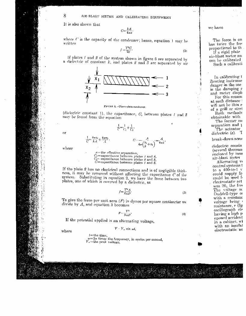
lf p]afps 1 nnrl 2 of t.!w system shown in figure 5 ure sopn.mtod h)· n diPlPctrir of constnnt k, nnd plnh's 2 nncl 3 nre sepnrntrd h~· nir
Fl<lURE 6.-ThtC'Cl·Jllrtte condensor.
(dil·l<•rt.rir constant 1), thr cnpnr.it.ane<\ 0, het.-ween platps 1 nn.d 3 mn~- lw found from t.lw Pquntion
or
where
C=--.~~_ ·=...4_' 4 (
·x,+ ) 4= 11" ic x2
J.:=thC' Pffective separntiort, C1=cap:wii.nnce- bctwcc11 plah'B 1 ttnd 2, G2 =capacit-nncc hct,Yccn plate" g ami S, C= capacitance bctwccll plate$ 1 and 3.
If the pln.te 2 hns no cleetrica.l eOnnpctions and is of negligible thick· npss, it may hr removed wit.hout a.ffectil1g thr cnpacitnncc C of t-hl' systrm. Substih1tlng in Pqun.t.ion 2, \'ire hn.vr the force hetwrPn f.wo pln.t.ps, mw. of whieh is r.ovt'rNi by n. dirlcet.ric, n.s
To give the forr.c per unit n.rrn (F) in dynes per square ccnt.imrter WI'. divide by A, and equat.ion 3 bt'conlr.s
If tho poknt,iul applied is 11.11 nlt.>rnnt.ing voltage,
where t=the time,
w=21r timcH the frcqnenc~v, in cyeleR per second, Vn=the pcn.k volt.ngc,
(4)
..
we have
The forec is on has twice t-he frl'' proportional to th
lf a rigid pln tc nir-blnst nwt.C'r ancon he cnlibrntcd
Such a. enlihrnt1
In cu1ibrnt.ing: t ibrntlng inst.rum<' dn.ngex in th~ usc is the dn.rnpmg r and motrr diupl1
For this reason a.t snell distnneC' ! will not be thin <' of a g:rill or strcl
Both mPthods obtninubiP with
The fornw1· m1 separation 1md l-
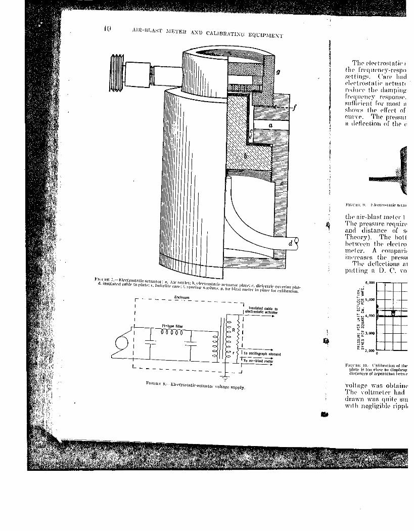
Thr actuator dielectric (c). 'I
break-dowri aero:
dielectric. constn (scvN·n.l thm~sn.n enclosPd by msn n,ir-hlnst n1rtP1·
AI tern a ting VI
control syste1ns t to n 400-to-1 '" could supply fr, could be used f~ rlcct.rost.n..tic net was 20, t.lH' frrl The yo}tagr n.c Ducldoll-typc o• with a. rpsistauc vol tn.gP h<'ing 1
rcsistunce. ,. (fig oscillogrn.p~l de> hflxing a ln};h p op<'-ned n_ccidrnt in n. cnbmc-t. wl with a.n insula! elcctrosta.tie · ac
JUation I mny lw
nrr srpnr:ll rd h;r iWpnrnh'd b~- :nr
I
2
"--- 3
n platp::; I n.n.d :1
·f negligible thic.k'<ll'itanrr C of 1-lH' 'ore(' bpt,wppfl t.wo
nre ccnt-imet('l' we
(4)
cond,
ELECTHO::iT.\TlC . .\C'lTATOR g
wr have (5)
Thr foree is one of attraction. sinel' oppositr dmrgr.s attrar.t; it hns twi('C' the fn~qnenC'y o[ t.hr imprcsF-l'd voltn-g:L' n.nd is invL'l'SPly proportional to the squan' o[ tlw l'ffl'clin• SL'pa.rn.tion.
H a. rigid plate is plnccd Hl'Ul' and parallel to the dia.phragn1 of the air-blast mrtrr and n. voltng<' is imprrssL'<l nnoss them, th<'. n ir mr.ter cnn lH' enlibrntC'cl if tlw voltage nnt1 l'l\'t~C'tive sr.prrrnt.ion <U't' known.
•
•
Such a enllbruting <lL'vicc is cnlh,rl nn t'lcct.rostntic ~let-unior. CONSTRUCTION
1n cullbrnt.ing tlw nir-blnst nwtC'r OlH' mm;;t bE' carpful that t.1w f'nl~ ibrn.ting instnmwnt docs nol nft'rd l1H' mdrr's n•sponsc. 'l'lw chiPf danger in thr usc of the electrostatic UC'-t.urrt.or in calibrating t.he ll1Pter is tlw dmnping efl'cl't of tlw thin a.ir space bC'tWC'en aetnn.t.or pln.te
and nH'tl'l' din.phrugnl. Ilor this renson t.\w plate of tho electrostatic octuator m11st be ki'j)t nt such dis.tnnrr from the. diaphragm t.ha.t. the n.ir spfiC-l' bet.\vern them will not lw thin PllOH~h to add apprPciahh, dmnping or t.akl' tlw form of a grill or stn•trlwd-wirr srl'l'<'ll dosN t.o Uw cliuphrngm.
Both nwthods n•dncl' t-lw :--wnsitiYit~Y and mnximum prN~surr.s obtainn.hlr with t.lH' nduator.
TlH' fornwr nwthod WfiS ndoptrd t-o nxoid the-. necrs~i t~~ of pn•mse
separation and pnralll'li:un hdwel'n grill nnrl cllaphrn~m. Thr aduntor plnk, ns shown at b~ iigure 7. wns et'Wl'l'NI with a
dielretrir (c). T·his protertt'd the equipment. in c·.asr of an rlrct-ricnl
brpn.k-down n.crosR thr nir gnp nnd added only~ of its thieknrss (k=the
dil'lectrie const.nnt) to t.he rfl'edivl' sepnration. As hi~h potentials (sl'Y<'l'H1 thousand volLs) nre usl'd in calibrating, thr plnt.P is <'ntin,ly l'ndosPd by insulntin[-1: material \Yhilt• tlH' di.aphrngm nnd cast> of the n.lr-hlnst nwtPr n.n• kept n.t ground potentia.l.
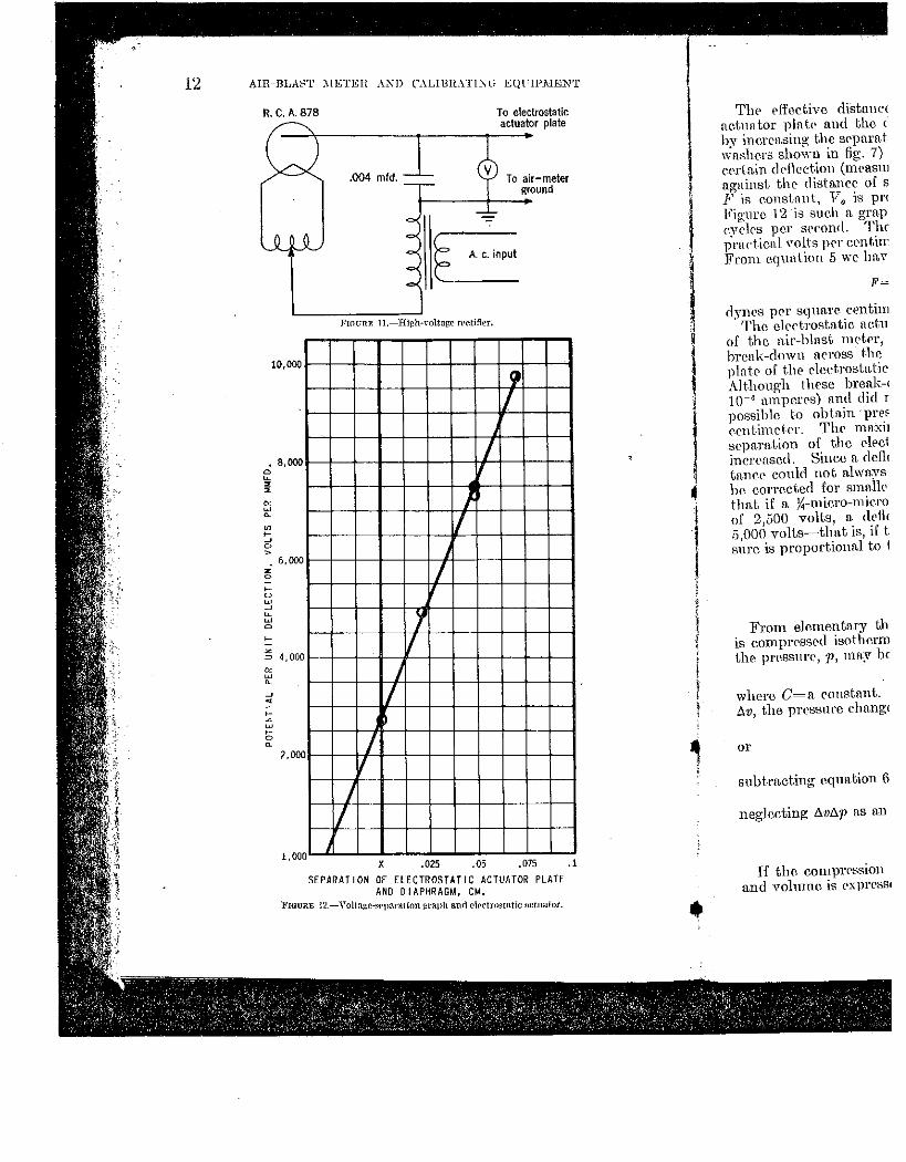
A\t.prnntinp: Yollap:r wns supphL'd hy eitJH'r o-f Lwo \Ya.rrl Lt>onard cont-rol syst.ems thrnll[-l:h n Jti-t.ypP, low-vass filt.Pr of ya.rin.bleindnctnncc to a. 400-to-1 ,~olLn.p:l' sll•p-up trnnsformt'l' (Hg. 8). 'l'lH~ generators could supply frNpH'Hl'il's from 20 to iJOO cydes pP-1' ~rcoJHl, whirl1 coulcl br mwd for cnliln·at-ions of 40 to l,OOO cye\ps per srcond (see ('\pc.t.rost.a.tlc n.c.tw1.t-or thL'ory). Thus, if tlw frequency of t.lu• yoling:c wns 20. tlw frPr{IH'HC'Y of t.lw force would he 40 cycles pPr spconrl. The yolt-n.p.:l' fl<'t'OSS the rh,etrostnt-ic nc.t.untor was rN~orded on a DmlrlPll-type oscillograph. Tlll' oscillogra-ph dC'ment wns in srri<'S with a n•sistanee. R (fig. 8), of sp,-prnl mrgoh1ns, drpPllfling on the voltage bC'ing used. 1)otentinls up to n,OOO volt-s ·w{'.l·r usPd. A resist.mH'<'. r (fig. 8), of 2,000 olnns was comtect.P(l in pnrnllel ·with tlw oseillogrnph rleln<•nt (approximntt'lY 1 ohm rcsistnnrC') to pn'vrnt ha.vin~ n high pot.rntinl on t.hC' oscillograph if the p\erncnt cireuit wrre opPnrd neeidrntally. All high-potr11t-in.l pnrts of the circuit wcrr kl•pt inn. enbind·. wlwrr tlwv could not hr tourhcd n.rci(h•ntallv. A rn.ble with m\ insnla.tinn rnr)able of withstanding 15,000 voltS led to the electrostu.tic. a.c.tuntor plate. ~
,,
10 AIH-BLAST .\IETEH AXU CALIBIL4..TIXli EQCtPi\IEXT
.Fit; t-Il£ 1.-I•:It•eirostn!ie llt'IWHor: 11, Air rullln: 1•. Pl!•elmstiHit· lletwtlur plnll·: c. tlil'lt•<·triC' ('<JWritl!! Jthtlt· d. in~ul!lled cnhl<' to plrttt•: t. hnkt•lilt• I'll,<:<·:' .. ~par·ing IIH~IH'rs: !1. :ur-l•l:::;:tlltt·lt•r i11 plar,• fur e;Jllhrn!iun.
Enclosure
I---------------~ lnst~l~led~bfe to
J electrostatic actuator
R
J Tn oscillograph element
Tu air-blast mete1
_j
l<'ll:t_onE 8.--Eit·t'troswtir-nctuHLor •·oh.n!!:u ~upply.
..
TlH' Pl<'dms.tnti<': tht• fn•qLtl'nr·~~-I'P~P 11 s<"ttings. ('an· had l'lt•ctrost n t i<· nctun tc rt·dtJ<'P tbt' dampin~ fr1•q I!PllC':V t'('S))OilSI'.
suffi1•ipnt for mm;t n shows tln• pfl\•ct of r.urYr. 'l'hr j)I'('SR.ln
rt dC'flf'et.ioH of thP t·
FJr,nn: !I. i".lt•t'IW<tnLil' !l.t'llH
tlH' nir-blnst nwk1: I The prC'ssure rrqmrp and distance of S•
Theory). Th<• hott IH't wp(•n t lw Plt'rf l'<} lllP1 er. A compnn~ illt'l'{'flS('S tlH' pl'l'RSI
Tlw derleel.ions n1 p1:tting n D. C. nl
6,000 ,--,--,-,
02
s: 5,000 1--1--1-+-
~: ~ ~ 4.~ 1--1--1-+-~-
! rooo 1-+-il--t--C>. ""2.000 L,-'--'--''-
l'H;\'RE to.- ('nlihratill~lllf tht• plfltt• i~ 1 on du~t· lu. <ltuphfflJ! di~!lmr1·~ ofst•pilrfltmn ht•L\\t•
vo}b1 o·t~ wus obtnill<' The ~oll·Inl'll'r hnd dr:nn1 wus quitl' srn w 1th ncglig-ihlP ripp} •
il']l'{'trk ~·on•rinl! p\llll'. p\at•t• for mlihi'Jlthm.
•led cable to tatic actuator ~
~
'Ogr:aph eleineol .~
:>last mete• ~
•
ELECTRO:-:.T.\TlC AC'LTATOH 11
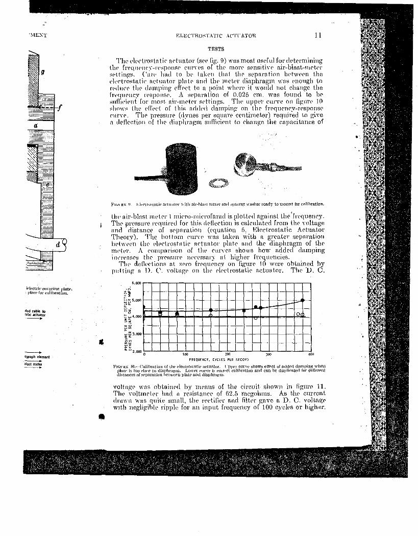
TESTS
The Plrctrostntir actuator (S{'f' fig. CJ) was most useful fordet.rrmlning thP frf'(jlH'lH'."-!'('8]10lHW CUI'\'l'S of thl' 11101'(' SPnsitiYl' n.ir-blnst-IHrkt' ~<·ttings. Cnt·t· hnd to bl' lrt\.;:ru thnt thr sC'pnrntion bdwN'Il the <'kctrost.ntie actuator plntf' and tlw met.pr diaphragm wns rnongh to J'('dl\C(' tlw dnmping rffPct to a point wlwre it would not change the frt•qHrncy n•sponsr. A srpnrntion of 0.025 cnL was found to bP sufllci<'llt for most. nlr-mrtPr st'tting-s. Tlw uppC'r enrvc 011 fip:nrf' 10 ~how~ illl' rf1'Pd of thi~ n-ddPd damping on thr frrqurncy-rrsponsP rllrve. Th£' pressurE' (d:vnes per squurr eentime.ter) re.quired t.o give n dPHrction of the <linphrngm sufli.eirnt t.o chnnge the cnpncitnnce of
FJr,nn: 11. J<.h•etru~ta~ic n.l"luaH•r with air-hlaot n;ewr 1111d ~p>H!Ill)!: washer ready to mount for t'lllihration.
tht• nir-blnst metpr lmi<To-microfarad is plottrd against the 'fn•quency. TllC' pressure required for thiR dPHcction is calculn.t.ecl from thr Yoltagc nncl distance of srpnration (equation 5) l~lect.rostatic Ac-tuator Theory). The bottom rurvL' was takC'n \Yitb n gren.t.cr srpn.rat.ioH lwtwl'L'll t.h0 t~lprtrostnt.ir nrtunt.or plate a.nd the diaphragm of t.lH• mf'tpr. A cmnpnrison of th<' C'lllTL'S shows how n.ddL•d damping in\Tl'flS<'s thr JH'eRI:'III'l' IH'ressary at higher frrqnencics.
Tlw dcflPctions nt :t.Pt'O f1·rqnenr.y on figurl' 10 were obtained by p1:lting n D. C. Yoltng(' on tlw rlPctrostntlr act.tmtor. Tlw D. C.
6,000
_.;.
0
"" 200 '"' ••• F!?EQUENCY, CYCLES PER SECOND
io'lt~\-RE JO.-·-Cnlihmtion nf (.he elcctrn~tntir artnntor. I ·Jl!ll'r cnne :;how::; rlfPct or !HldNI dampinl! when platt• is 1<10 rto~l' to llillJlhrap:m. Lmwr rurn- b curr,rl rnlihrntiun nnd can br duplif•fltt•d for di!Ien·nt ,\i~tanrt•s of se1mration hl't ''''PD ttlalt' ant\ diaphragm.
voltngl' wns obtained by rncans of the eirenit- shown in figure 11. Tlw Yoltinl'll'r had n rPsist.mH'L' of 62.5 megohms. As the em-rent drawn wns quite smnlt, thl' rPrti(ier a.nd filt.Pr gave a. D. 0. volta~r wtt.h negllgihlL' ripple for nn input frequency of 100 cyeles or hightn· .
,,
12 AIR-Biu\S'l' :\!liTER AXD (' .. \LIBR.\Tl~L; EQFIPMENT
R. C. A. 878 To electrostatic
---T------...-----.-•::_c::_t"::_•:;tor plate
10,000
~ ~ ~ 0
:>. 6,000 z 0
~ 0 w ~ ~ w 0
:: z => 4,00 0
"' w ~
~ ~
2,000
1,00 0 J
.004 mid. To air-meter ground
+----+-~ ...
Fwnm 11.-High-mltag(' n•ctifi~r.
9 IJ
,/
} II
I
'/ I
)
II
I
)
il X .025 ,05 ,075 .1
SEPARATION OF ElECTROSTATIC ACTUATOR PLATE AND DIAPHRAGM, CM.
FIGURE 12.-Voltagc-~l'pl'rH.tion graph aurleh•etro~mtic act.uator.
Thr rffe.etive distnnc< aetuntor plntP and Lhc < by incrcttsin~ the scpnra.t 'Yn~lwrs shown in fig. 7) eP-rtn.in dl'ftcct.ion (mcasm a.gninst the distance of s F i_::; eonstnnt, v·o is pr< Figure 12 is suc.h n. grnp c.ycks per spron<l. Thr prnct.ien.l Yolts prr ccnt.iir Frmn equation 5 we bn.v
dynes per squn.re centim · The clrctrostu.tie aet11
of the n.ir-hlnst nwt.er, lwenk-dowu n<'ross t.he plrrte of the eleetrostn.tie Although these break-< ln-• .uripcres) and did r possihlc to obtain- preE c.ent.irnckr. The ma.xi1 separation of the dect incn~nscd. Sinee a deft• tnnee could not alwn.vs he eorrccted for smft.ll<' thn.t if n. X-micro-miero of 2,500 volts, a <It'll< 5,000 volts-that is, if t. sure is proportionnl to l
From elementary th is cmnprrss('(l isotherm the pressure, p, mn.y be
where O=a constant. llv, t.he pressure c.ha.ngl
or
subtracting equation 6
neglecting !!.mlp as fill
If the compressiOn and vohnnc is PXlH'l'SS•
lt.lP!\IENT
·lectrostatic Jato~ plate -air--meter ground -
I
.075 .1
JR PLATE
·actuator.
PIS'l'O?\PHONE 13
The cffectiYe distance for srprr.mtion between the electrostatic nctuntor plnk n.nd the diuphrngm of the air-blast n1etcr was found by inc.rensing t1w seprrru.tion by known £unounts (by menns of spacing wnshC'l'S shown in fig. 7) and plotting the volt.n.gcs required to give a cPrtnln ddh·ct.ion (n1rasm·pd ln mirro-mi<'rofn.rn.ds capacitance change) ngninst thl' clisbmce of sepn.rn,tion. F'rmn equation 5 we see. that. if F \s constnnt. ro is proportional to :r., tlw dist.nnc.c of sepn.rn.t.ion. F'lgure 12 is surh a. graph with a.ll points taken at a frequrncy of 80 eyrlrs prr :wrond. Tlw graph in figure t2 has a. slopr of 96,500 prnd-ienl ,-olts pPr cC'ntinwtt-r. or :122l'leet.rostatic volts per centimeter. Frmn equnlion 5 we h:1Ye
F~-J- (!")' ~ ~ (3221'~4,100 ti1r .l X1r
dynL'S }Wl' s.qunrf' crntimctrr per rnicro-mie'l·ofa.rnrl deftection. The C'lpctrostntir nrtnnt.or could only be used for sensitive settings
of thr nir-l1lnst mdt>T1
as hi?;l~ Yolt-nges would cause an clectrieal brC'nk-down nrross the rt.ir gnp hrtWL'l'll Uw dieleetric covering the plak of thr ele-cLrost.n.tie actnato1· nnd t.l\C' diaphragm of the n.ir meter. Although these break-downs pnsscd negligible eurrent (less than 10-~ nmperes) mul did not dumnge nny f'C{Uipnwnt, they 1na.de it impo~sihlr to obt.nin pressures greater tl1nn 1,400 dynes pel' square r.rntinll'lPr. The mn.:ximnn1 pressures obtainable decreased as the Sl'pnrntion of Lhe dPrt.rost.n.tir netun.tor plate- and the diaphrng1n inrn•nsed. Sinee a dPflrction of 1 Jnicro-microfaracl change in capneit-nnrl' rould not always be obt~1incd. fl;'raphs sueh as figure 12 hn.d to lw corrertrd for smn.lh•r df'-flrrtlons. F'rom equn.tion 15 it is evident thn.t if a %-nlirro-mierofnrad dl'fkction was produeed by a pote-ntial of 2,500 voltg, fl deflt>rtion of 1 mirro-1nirrofnrad would l'equire 5,000 volts- -lhat is, if the distunrt> of sepn.rat.ion is constant, the pressure is proportional to the squarp of the v·oltu.ge.
PISTONPHONE
THRORY
From elen1entn.ry thermodynamies we know that if n perfect. gas is {'.on1pn~ssNl isothermnllv, the relation between tbe volume, D, u.nd the pr('ssun', p, mn.y hr r.Xprrssed by the equation
~-~ ~ where O=n eonst.nnt. If we c.hangr t.hc volume by a. small arnount, Ll.v, Uw pn•ssure ehungcs n, smnll anwunt !J..p, so that
(v-f-tw)(p-1-1\.p)~C, (7)
Ill or vp-l-p6.v+ 1uj,p+ 6.v6.p= C, (8)
snhtraeting equation 6, p6.v-l--v6.p+6.vL\p=0, (9)
ncglp.cting !1-v6.1J u.s nu infinitcsinm.l of t.br second oTder, this bceomes
6.p= -~· (10) Jl /1
If the r.ompn•ssion is ndinhatic. and Yolume is pxpn•ssPd by
f.lw rPlnt.ion between thn pressure
Jll'"' -- c, (11)
·•
14 AIR-BLAST METER AKD CALIBRATIXG EQUIPMENT
where 'Y is thr rn-t.io of the specific heats at constant volume. Its ,~nlur for nir nt. nornwl tcmpornt.urr is 1.40. Again, changing t.lw Yolmne by n small a.Jnount, b.~', mHl ncp:lerting infinitosimn}s of t}l(• sceond or higlwr ordrr
1 we hn.vc
(12) by n similnr dnw_,loprnent..
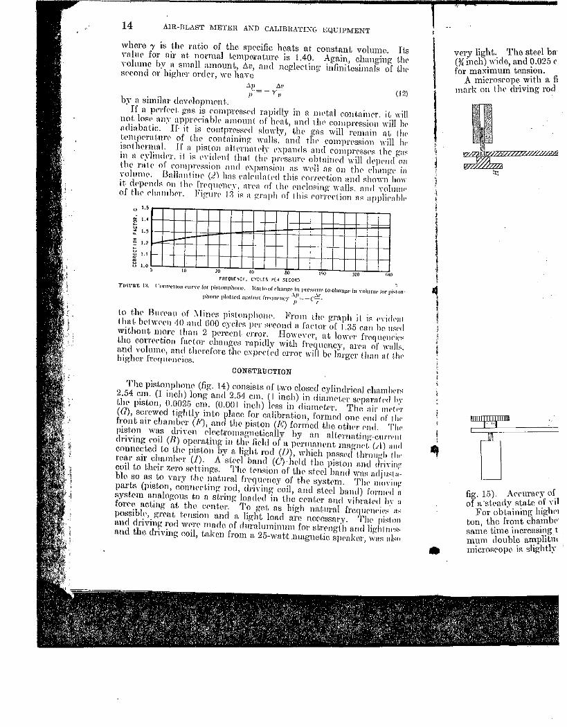
If n pnf<.'cl. gus is romprrss{'(-{ rapidly in fl 1HL'tnl r.ont.niner, it will not. los!' nny apprrciahlP amotm1 nf hrnt, nnd thl' c.on1prr-ssion will hP ndinbntic. If- it is conlprc•ssrd slowly, tlw gns will remnin nt. !Itt• tempPrn!.m·r of thr contnining wn1ls. nnd thl' COlllJH'C'ssion will lw isot1wrmnl. lf a piston nHPrnnlPly t•xpmuh:; nlHl comprrssPs thegn~ in u cylindi'T. 11 is t•YidPld 11w1 lhl' pn•ssurt> obtnilH•d will dPJH'ncl n11 the 1'111<' of eompr(•ssion nnd rxpnnsioll :1s wt'll ns on thr rhnngL' in 'Tohmw. Bnllant inr (.2) hns rnlrtdntt•d this rorrertion and shown how it. rlPpP!His on 1lw frPqllL'llt'~Y, lll'l'll of tlH' rnrlos.ing \Ytllls. nnd Yolumr· of tlw ch:unhc·r. Figure 1.1 is n grnph of !his r01Trc1ion n~ applienhiP
u 1.5
~ I. • ::_ 1. 3
' ' ~ l.
3 l. o, "
! ' i '
' I ' i i " " 80 t<iO " 1;4(1 FREQUE~Cr, CYCUS PE~ SECO.~J
'FlrH'RE 1:;. r ·urn•el\rm I'Ur\'1' [or pi~t-nnplwrw. Hat in of l'ilfi!H!t' in prr~~nn• to Chflng-r• in \-ohrlll<·lnr pi•! on
phmw plntrt•<l a>::nin~r fn'<!lll'lll'\' .'!.Jl=-(~. • Jl I
to tlw BurPnu of ~li1ws pistonphOJH'. From tlw graph it is I'Yidt'lll lhn{. b<'i\VPPn 40 mal GOO c.yr.l<'s JH'r sPCOlHi n fnrtor of 1.35 enn lw usl'd wit.hont more tlwn 2 pt•re<•nt- l'l'l'Or. Ho\H'Yl'r, at 10\n•r frNJIICllf'i('." the c.orrrrtion fartor c.hnnges rapidly with frpqucncy, m·ra of walls. n.nd volume, nnd t-.Jwrcfore th(' exprcfpd error will be Jnrger than nt !-hr• higher fTNJII<'JH'ios.
CONSTRUCTION
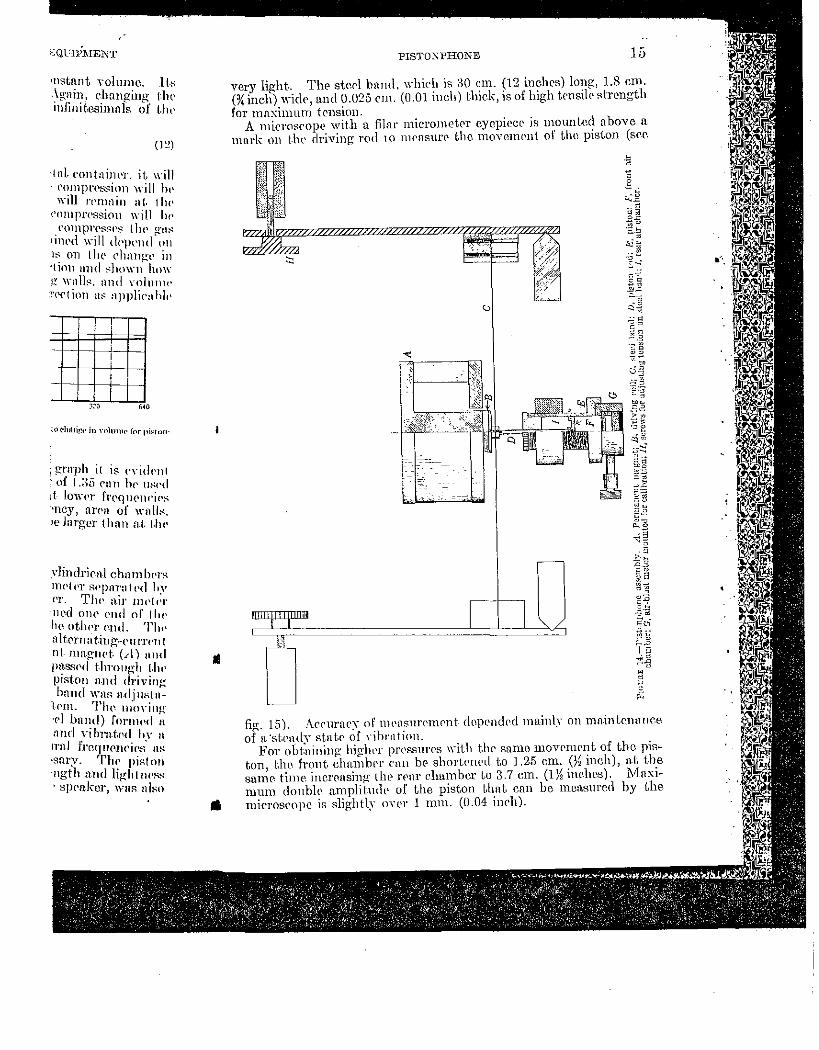
The piston phone (fig. 14) c.onsjsts or t.wo closed c.ylindricn.l rJmmiH'rS 2.54 em. (1 ineh) long u.nd 2.54 em. (I inch) in dinnwt.pr SPJHlrll1f•d hy the pist.on, 0.0025 em. (0.001 inch) lf'RS in dianwtf•r. Tlw nir nw!Pr (G), screwed tightly into p1ncc for cnlibrn.tion, formed one <'lld nf 1111' front nir chnmlwr (F), nnd tho piston (E) formed tho otiH•r '''"'- Tl"· piston was drin•n clr-ctromagneticnlly by nn nlt.rrnntiiw-cuJTI'III driYing r.oil (R) operating in Llw field of a permanent magnd~ (A) a11d connected to t.lw piston by n. light. rod (/J), whieh passpd j.Jn·ough !ltr· rcn.r air chnmlH•r (!). A stP<'l band (C)·hdd the piston nml driYin~ coil to t;Jl<'ir Zt•ro srtt-ings. The tf'nRion of thr sted band wnf: n.dju~1:~blc so as t.o vary t.lw nn.tura.l frt•qtH'ney of the syskm. Tlw llloYinJ! pn.rts (piston, eomwct.ing rod, driYing eoil, and sterl band) fomu•d n system mwlogous t.o a st.ring· loaded in the crntrr and vihrnlf•d hY a fOre~·· n.eting 'n.t the c.<•nt.cr.' To get n.s l1igh nn.t.urnl freqtH'IH'iP~· H~ poss1hh', grcnt, t.<'nsion and a. light load are ncerssnry. The• pi~lnn and driving rod Wt'l'C' made of durnluminnm for strrngt.h nnd liuh! lli'S~ n.nd the driving coil, taken from a 25-wntt.magnet.ic s}waker
1 '~'liS ulso
~ j
I , !
•
very light.. The steel ba· (% inch).wide, a.nd ~.025 c for mnxm1um tensiOn.
A microscope with a. ~ 1nark on t lw driving rod
;""'I'ZI"'""
0 fig. 15). Acrmac;~' of of a·st.t>ady sta.tc o.£ nl
For obt.ninlng luglw1 ton the front chamh<·· san~e time increasing t nnun double amplitnt 1nicrosrope is slightly
•nstnnt Yolumo. Jt.~ . ~gail~, changing nw mfimtBsimnls of t.Jw
(I~)
·tnt rontnint•r. it will l'OillJH\'ssion will h" will l't'lllllin at. t ht•
cnmJH'PssimJ will IH· . comprt>sst•s tlw g-n~
lllll'rl will dPlll'nd 011
1s on thl' eh:l1Wt' in ·tinn :111(1 s.lwwnr-hnw g wnlls.. nnd n1hmw l'PC\ ion :1::::. npplic:J hit~
i I i
]::"(} '"
; grnph it is. £'Yidt·nt .·of l.:~tl c·an lw II~('< I :t- lmn•r fTN]llf'JH'ic·~ •ney, nrpa of \\'11 11~. 'e huger than n.t. t.lw
yJindricnl ehamhprs nwt.pr :::wpara t t'd hv 1'1'. Tlw air nwt,;r 'JWd OJH' end of IIH· h0 oUwr Pnd. Th1· nltrrna t.ing-euJTI'Tll nt. HHt.gnd. (..-l) nnd IH~.ssc•d t.ln·ou~h (.h1' piston n.nd drivin1r band WHR adjustu~
lPm. Tlw nloYilw ·p} bnnd) fornH•d ~ :tnd Yihra.t.Pd hr n n·id frcqnml<'ic·.s· m: ·snr)T. 'rhr piston ngth n.nd li~ht fl('Ss
· spPakcr, wns nll-'n
•
PISTO~PHONE 15
very light. The ste.rl bnnd, which is ;JO em. (12 inches) long, 1.8 em . (% ineh) wide, a-nd 0.025 em. (0.01 inch) thick, is of high knsilr Rtrcngt11 for mnxinnun tension.
A Inicrosropl' with a filar mic.rometrr cycpircc is mmmtccl above a mnrk on t.lw driving rod to nwasurc- the moYemPnt of t.lw piston (srr.
fig. 15). Arrurnry of mPnsnrrmPnt dopt•nc!Pd mainl~Y on ma.intf'JHHJf'.e of R·st.pntlY stnt.r of Yibrntion.
For obt:nining hig·1wr pn•ssurrs with thr sn.n1e rnovrmrnt of the piston, t.lw front chmnlwr cnn bC' shortpm•d to 1.25 em. (%inch), a,t the sam0 tinw increasing the rPnr eha.mhcr Lo 3.7 em. (0~ inehos). 1vlnximum double umplilwlt• of the piston t.hnt can be n1cn.surcrl by the mierosropc is slightly OYl'l' 1 mnL (0.04 in<'h) .
16 AlR-BLAST 2.1ETER AND CALIBRA'l'IXG EQ("If'.:\1EXT
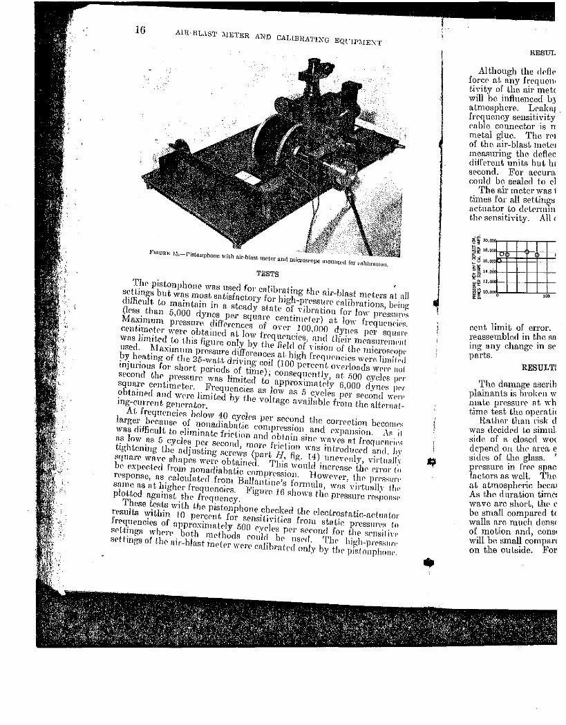
FWIJRE 15.-l'istonphonll with air-blnsc meter and microsrope monntt'd for t·nlibratirm.
TESTS
The pistonphone was used for cnlib,·ating the air-blast mrtprs at nil sett.ings but was most sa.tisfactory for high-prc•ssun• enlibrntions, !win~ difficult. to maintain in a steady state of Yibrntion for lo\\- pressJII'<'s Orss than 5,000 dynes per squa.re centimeter) at lo\\- frequrnei<•s. Maximum pressure difl'erences of OYPr 100.000 dynes per squnn• crntimr.trr were obtnined n.t Jow frcqnrneirs, nnd their mPnsurrmt'll! was limited to this figure only by thP field of Yision of the microscope used. I\1 u.ximmn pressure differences at. high frrqtlf'ncics wPrc Iimifl'1l by hf•n.ting of the 25-wnLt driving coil (100 perePnt, (J\-erlonds werP noi injurious for short periods of time); consequently, at .. 500 cyclt•s Jl<'r second thP pressure was Iirnited to approxin1a trly 6,000 dyn('S ]H'r square centinwter. Frequencies as 1ow as 5 cyeh's 1)(11' second W('J'r•
obtained and were limited by t.lw voltage n.vniloble from the altemnling-eunrnt, grnrrator.
Ai. frequPnc.irs below 40 cyclrs per second the correction bcconw!' larger becnusc of nmutdiubnt.ic compn•ssio11 and expansion. ~\~ if was diffieult to eliminate friction and obtain sinp wavps at frequrnC'ir'" as low as 5 cycles per second, more friction was introduc<'d aut!. hy tigiJtoning tllo adjusting screws (par(. H, fig. 14) unoH'nly, viJ·ilJn/ly squa.rr wave shaprs \YPre obta.inl'd. This would incrcusr thr f'l'l'or fo be expcct.ed from nonadiabatic compression. Howevt•r, the Jll'l'RSIII'<' rrsponsc, us cn.lculatcd from Bni1n.11tinp's formula, ·wn.s 'Tirtually lhr• snme as at higher frequenciPs. Figure J 6 shm\-s the prpssurc rospons1· plot.tcd against the frl'quency.
These tests with the pistonphone checked the electrostn.tic-ndunlor l'Psults within 10 pcrernt for SPnsitiYit.ies from static pressurPR lo frequencies of npproximatrly 500 cycles pPr Sf'cond for the SPnsilin· Rf'Hings w1wrp bot.h mPthods could hP usrd. TI1e high-pi'('S-"III'C' srttings of t.lw air-blast indPr wrn' cnlihrnt('d only by tlw pistonphnnc.
J
RESUL
Although the deflt• force at any h:cquen1
tivitv of the mr met< will 'be influenced b) atmosphere. Loalmt . frrqucmcy sensitt:·tty en.ble connector 1s n metal glue. The rel of the air-blast motel measuring the defiec difft•rcnt units but ho sPcond. FoT aeeura could be sealed to el
The air meter was 1 times for all settin10s actuator to de:•tcrmm the sensitivity. All <
cent liinit of error. reassembled in the sa ing any change m Sl'
parts.
RESULT!
The damuge nscrib plainants is hrokPn w 111ate pressure nt w~ time. test the op~.ratH
Rather tlmn nsk d ViTas rlecidp.d to sinlul side of a closed \VO<
depend on the area ~ sides of Uw glass. pn'ssure in freC' spac factors as well. The at at.1nospheric bccn.1
As the duration tiinC': wa vc arc short, tlH' c be small compared t< walls arc much dens< of motion and, const will be small eompan on the outside. For
"·
" nt nH ~,!wing 'PSSIII'f'~
ll'IH'1(':4,
squnn• )'Pl-lWilt
I'OS('(tp!·
lin1ih>d t'I'P no(. ·h•.s JWI'
)l'S JWl' td W!'t'('
tP.rnn t.-
·P-t'Otnt'~
As it tlf'll{'JP~
md, hv irt uall~· '1'1'01' to •l'l'RSlll'('
<lly tlu• 'S}WilRP
ct lUI t-or 111'(':4 t (I ·nsit i\"1' •J't'R~III'!'
1phnnl'.
•
•
RESULTS OF PRELIMINARY FIELD TESTS 17
Although tlw dcfll'ction of the diaphragm is the saml' lor a certain forcP at a.ny frequency from zero to 500 cycles prr second, t.he. sensitivity of thr air rneter (as discussed under Air ~{c-ter Charu.cteristic.s) will hL' influrnced by any leakage between the air clwn1lwr and the ntmosph(;'n'. Lraka.gC' m·onnd the dia})hra.p:m would shmv on th(• frrquency sC'nsitiYity ca.librat.ions. Possibility of lca.kng<' through tho c.nble connector is mu.de negligible by sealing the connections with ml'toJ glnr. The rl'maining possibility for leakage tluough the rear of the air-blast meter is t-est.rd by reversing it in the piston phone and nu•ns11ring tlw deflection fron1 known pressures. R<~sults vn.ry with different units hut have not exceeded 15 percent error at 5 cycles per spcond. For accurate n1easurernent of lower ·frequencies the back could be sealed to eliminate this error.
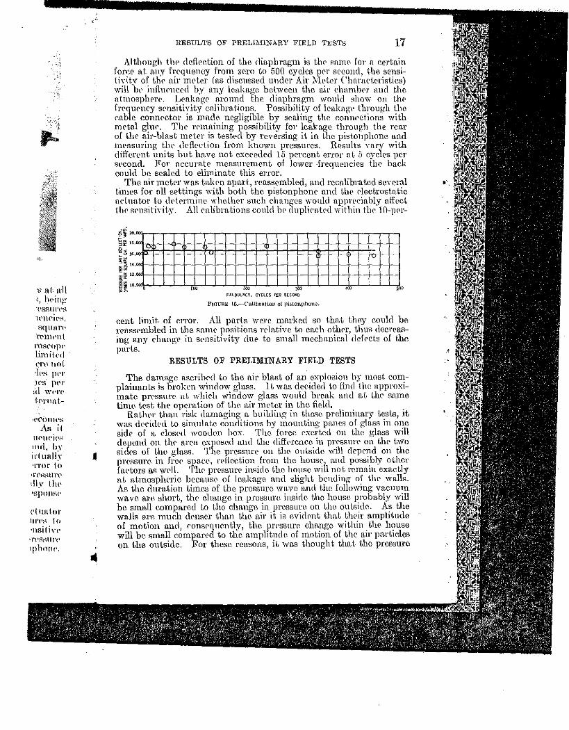
The air mctpr was ta.kPn a.part, reassembled, and recnlibrated several times for all settings with both the pist.onphone and the electrostatic uduator to dl't('rminc whether such changes would apprrciably a-ffect tho st•nsitiYit.y. All eulibmtions eonld hr clnplicrrtNl within the 10-]wr-
ll§i 11111"1111111111 ! II . - - -
11111"111 !00 ~00
FREQUENCY, CYCLES P£fl SECOHD
FIGURE lG.-C'alihration of pistonphone.
cent limit of error. All parts were marked so that they could be rct1.ssrn1bled in the snnH' posit.ions rrlative to each othrr, thus decreasing any changP in sensitivity due to smnllincclumical defects of the parts.
RESULTS OF PRELIMINARY FIELD TESTS
The damagt• ascribed to the air blast of an explosion by most complainant.." is broken window gluss. lt was decided to find Ute npproxirnate prpssui'f'- at whieh window glu.ss would break and at tlw same time test the operation of tlw air meter in the field,
Rat.lwr tha.n risk du.rnn.ging a building in thme prelinTinar:y tests, it was decid('d to sirnulate conditions by mounting pmws of gla.ss in one sidr of a. clos<'d wooden box. The fol'ce. exerted on the gla.ss will depend on thr area C..'\posnd and the fliff<'l·cnec in pn•ssurP on the two sirlps of tho glass. The pressure on tho outside '\Vill dep<.'nd on tho prrRsure in frep spa.ee, rPflcetion frorn the house., mul possibly other faptors tts well. Thr prcss1U'P inside the house will not remain cxa.etly n.t n.t1nosplwric bccu.usp. of leakage und slight bending of tlw walls. As the duration tiniCs of the pressure wa.ve n.n(l tho following va.cuu1n wave Rro short, thr chRngc in pressure inside tho house pl'ohably will be snutll cornpared to tho change. in pressure on t.he outside. As the wu.lls are 1nuch d(•nse.r than the air it is evident thn.t their mnplitude of motion and, consequently, the pn'ssure. change within tJu'- house will be small compared to the a.mplitudc of motion of the air particles on the outside. For these reasons, it was thought that the pressure
. 18 AIR-BLAST METER AND CALIBRATING EQUIPMENT
rwcPssm·y t.o break the glass mount.rd in t.hr box would approximn.t.<'ly equal t.hat. nrcrssn,ry to brC'ak windows in a house.
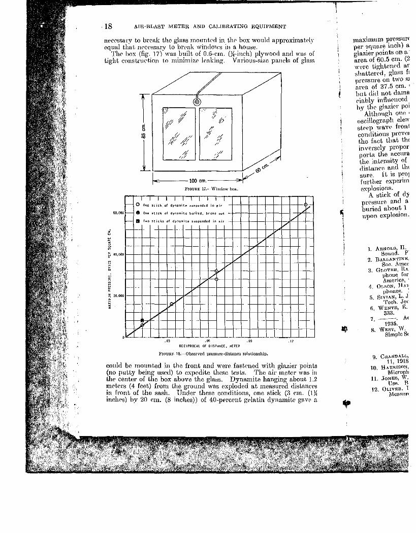
The box (fig. 17) was built of 0.6-cm. (Y,-inch) plywood and was of tig-ht construction to minirnizc lrnking. Various-size panels of gla.ss
T :;, .,· ). $ ,; ·,
-tP jf' f; E r // u
:3 //( ~// '/{
;f /'
l y/ ///
// // /'
// // 'J :/ ~
a:> .....
1-E-----100 em. ------'0¥~ FIGURE 11.-Window box.
I I I I I I I I I I I c- 0 Ooe stick of dyn~mite suspended in ~ir
,-- • One stick of dynamite bud·ed. broke o~t
- II r .. o sticks of dyn~mite suspended in air v /
60,000
I/ /
' /
v /
/ /
/
v ~ 20.000
' ;
/
"' ,V ·" RECIPROCAl OF OISTAUCE. METER
FIGURE 18.-0bserverl pressure·distuneo rdntionshtp,
could be mounted in the front and were. fastened with glazier points (no putty being used) to expedite these tests. The air meter was in the center of the box above the glass. Dynamite hanging about 1.2 mct·<'rs (4 feet) from the ground wns exploded at measured distances in front of the sash. Under these conditions, one stick (3 em. (1){ inches) by 20 em. (8 inches)) of 40-prrcent gdatin dynamit<• gave a
i '
•
mu.ximu m press11r€ per squaTe. inch) n glazier points on a· area of 60.5 em. (2 wPre tightened ar slmtter<'d, glass f: pressure on two s1 n.rea of 37.5 em. ' but di<l not <lama eiably influ~nccd by the glazrer p01
· Although one ' oseillograph elen· stN'-P wn.VP front conditions prcvm the faet that tlu inversely propor parts the ~ccura the intcnstty of rlistan<_·r. and t.hl sure. It is pro1 further cxpeTim r.xplosions.
A stiek of dy pressure. and n. buried about 1 upon explosion.
1. AnNOI,D, H. Sound. p·
2. BAJ.I,ANTINE. Soc_ AmcT
3. GI.OVER, RA phone for America, ·
4. 0T.F.ON, HA:f phones. :
5. SwiAN, L. J Tech. Jor
6. "WENTE, E. 333.
7.--. A< 1935.
8. WEsT, W. SimpleS<
9. CRANDALl., 11, 1918
10. HARRISON, Micropb
11. JoNES, \Y. Use. B
12. OLIVER, 1 M.easurt
·l.Y
of ISS
tnts ~ Ill
1.2 l<'PS
(1 Y. " 11
BIBLIOGRAPHY 19
maximum pressure of 60,000 dynes per square centimeter (0.9 pound per square inch) at 7.5 meters (25 feet). This test first loosened the glazier points on a pane of double-strength glass haYing an unsupported area of 60.5 em. (23'){, inches) by 77.5 em. (30~ inches). When these "·ere tightened and the test was repeated, the pane was completely "hattered, glass falling both inside and outside the box. The same pressure on two sina.ller, singh•-strcngth pn,nes having an unsupported area of 37.5 em. (14% inches) by 60.5 em. (23)1: inches) shattered one but did not damage the other. It is thought that brmtkage is appreciably influenced by inhomogeneities in the glass and strains caused by the glazier points, but tests for these factors were not conducted.
Although one object of these tests was to determine whether the oscillograph clements and the air· meter could aecuratcly follow the skcp '''ave front resulting from exploding dynmnite in air, advrrse conditions prevente-d accurate analysis of the wave front. Howevl'r, the fact that the maximum pressures measured were approximately inversely proportional to the distance, as shown by figure 18, supports the accuracy of the Inea.surmncnts, since, neglecting damping, the intensity of the wave should va.ry inversely as the square of t.lw distance and the intensity is proportional to thr. square of the pn'ssure. It is proposed to use crystal clmnt-.nts in the oseillograph for furthm· experimentation with the steep wave front found close to rxplosions.
A stick of dynamite e"-ploded in the air gave about six times the prrssure and n. steeper wave front than a like an10unt whirh wns buried about 1 foot underground at the same distance and broke out upon explosion.
BIBLIOGRAPHY
CALIBRATION OF MICROPHONES
1. ARNOI.D, H. D., AND CRANDALJ,, I. B. Thcrmophone as Precision Source of Sound. Phys. Rev., scr. 2, vol. 10, 1917, p. 22.
2. BALJ,ANTINE, STUART. Technique of Microphone Calibration. ,Jour. Acm1s. Soc. America, vol. 3, 1931-32, p. 319.
3. GLOVER, RAJ,Pil P., AND BAUMZWEIGER, BENJAMIN. A Moving Coil Pistonphone for Measurement of Sound Field Pressure. Jour. Aeons. Soc. America, vol. 10, No. 3, January 1939, pp. 200-205.
4. Ot,soN, HAmn F., AND GOJ,DMAN, STANFORD. The Calibration of Microphones. Electronics, val. -3, 1931, p. 106.
5. SrviAN, L. J. Absolute Calibration of Condenser Transmitters. Bell System Tech. Jour., val. 10, 1931, p. 96.
(). WENTE, E. C. Thermophone. Phys. Rev., ser. 2, val. 19, April 1922, p. 333. .
7. ---. Acoustical Instruments. Jour. Aeons. Soc. America, val. 7, No. 1, 1935.
8. WEsT, W. Pressures on the Diaphragm of a Condenser Transmitter in a Simple Sound Field. Proc. Wireless Sec., Inst. Elec. Eng., vaL 5, Hl30.
9.
10.
11.
12.
CONDENSER MICROPHONE
CRANDALL, I. B. Air-damped Vibrating Systems. Phys. Rev., ser. 2, vol 11, 1918, p. 449.
HARRISON, H. C., AND FLANDERS, P. B. An Efficient Miniature Condenser Microphone System. Bell System 'l'cch. Jour., vol. 11, 1932, p. 451.
JoNEs, W. C. Condenser and Carbon Microphones, Their Construction and Use. Bell System Tech. Jour., vo1. 10, 1931, p. 46.
OLIVER, D. A. An Improved Condenser Microphone for Sound-p1' Measurements. Jour. Sci. Instr., vol. 7, No.4, 1930, p. 8.
f: ~ 20 AIR-BLAST METER AND C'ALlBRATTNG EQliiP:\IE~T
13. 'WENTE. E. C. A Condenser TransmiU.er. Phys. Rev., ser. 2, vol. 10, 1917, p. 39.
14. ---. An Imprm·ed Condenser Transmitter. Phys. Rev., ser. 2, val. 19, ).lay 1922.
EXPLOSION RECORDING GAGES 15. 1\:E~T, R. H., AND HoDGE, A. H. The Use of the Piezoelect.ric Gage in the
!\IeasurPment of Powder Pressures. Tram;;. Am. Soc. :VIcch. Eng., vol. 61, :-lo. 3. 1939, pp. 197-204.
16. h:EYEt'\, DAviD A. 1
1
iezoeledric :rvrcthod of l\Icasuring Explosion Pressures. 17.
Pl1il. i\Iag., vol. 42. 1921, p. 473.
l\IAnTIN, E. S., Al\'n C . .uns, D. F. TIPsista.ncP- Engine Indicator. Jour. Soc. 18.
Auto. Eng., vol. 23. 1928. p. 87. TioEss. Lons C. A Condenser-type High-speed Engine Indicator. Rev. Sci.
lnstr., vol. 2, No. G, June 1940, pp. 183-195. 19. ScHHADER, H. J. Piezoelectric Engine Indicator. R. G. A. Rev., vol. 2, 1937, p. 202.
RECORDING OF EXPLOSIVE WAVES 20.
Es.cLAKGON, E. L' Aconstiqne des projectile& et des canons. GauthierYillars, 1925. 21.
GA W'I'HHOP, D. B. VPlocit.y of the Shock Wrwe. Jour. Franklin Ins~ .• vol. 22.
219. 1935, p. 471. '
GA WTHROI', D. B .. Sm~rmmn. \V. C. F'., ANn PERHOTT, G. ST .• r. The Photo~raphy of \Yan's and \"ortiecs Produced hy the Discharge of an Explosin' .
23. • Jom. Franklin Inst .. ,-ol. 211, 1931, p. 67 .
• Jo:-.Ef:, ELWYl';, Photop;r:lphic Study of DPtonation in Solid Explosives. 24. Proc. Royal Sor. London, ser. A, vol. 120, lll28, p. 603.
\ln.um. D. C. Sound \\'aves, Their Shape and Spf'Pd. Macmillan Co., 1937, 164 pp. 25.
2G.
27.
28.
29.
30.
31.
32.
I'AL\tAN, \YrLLIAM. DPtonation \Yan' in Gaseous :\[ixturcR and the Prcdetonation Period. Proe. Ro~·al Soc. London. S{'l'. A. \'ol. 120, 1928, p. 90.~
SEISMIC INVESTIGATIONS BY THE BUREAU OF MINES
Lrm. F.""., AND InLAND, G. A. Const.ruction of 1\Iast.er 1\Icrhanical Oscillator for Te~tinp; SC'ismie Recorder& and Other Allif'cl Apparatw:. BurPnu nf :\lint's Tech. Pappr ,1)18. 1932. 17 pp.
lRL\ND, G. A. A Studv of Sonw Seismometers. Bureau of l\Iincs Tech. Pappr 556, 1934. 48 pp. I~m·:. F. W., TnOl•ml~K. J. R., AND WINDEB, S. L. Earth Yibrat.ions Cau::~ed
hy Quarry Blasting. Bureau of Miner:: Rf'pt. of Jnvcstign.tions 3310, J030, lf) pp.
Tum-:NJ•:r.:, .J. R., A;o..;n ".1!'\DI~f\, S. L. Earth Yihration.-- Caused by Qnnrry HlaRiiHp;. PI'Og:res.o: H<'pOI"I 1. Bm-cau of :\lines Rcpt.. of Invest.iP,"ations 33;)3. 1937, 73 pp.
----. Eart.h Vibra.t.iow;; Cauo:e<i by i\finc BlastinP,". ProgrcsR RepnrL 2. Rmeau of i\[inp~ Hept. of lnYestigafion::: a407, 193R, ·10 pp.
----- Hou:=;e l\[oYclllcllt Cnu~Nl lw Ground Vihratirms. BmPatl of .i\1 inC'R n('pt. of I 11\'('sj iP,"ationR 3-t:~ 1' 1 93.8, 14 pp.
Tmmx1·:N, J. R .. \Ynnn:s. S. L., ANn lnJ.:J,AKD . .-\. T. House i\lovf'mPnt Tnduc<'rl hy i\Iechanica\ Agitation anri Quarry B!Hst.ing. Progress Reporf 3. Bureau of i\Iines Hept. of In\·cstigations 3542, I g,iO, 36 pp.
MISCELLANEOUS
33. PENDim, HAROLD, AND DI•::L 1\Lm., W. A. Handbook for Electrical Engineers' 2<1 eel., 1922, pp. -~13--414.
34. Woon, A. B. .-\Textbook of Sound. The .:\Iacl\lillan Co., 1937, .119 pp.
0
,