Embed Size (px)
Citation preview
The Journal of Undergraduate Research The Journal of Undergraduate Research
Volume 17 Article 5
3-20-2020
Design of an Affordable Rotating Drum Electrospinner for Design of an Affordable Rotating Drum Electrospinner for
Classroom Education Classroom Education
Peder Solberg South Dakota State University
Follow this and additional works at: https://openprairie.sdstate.edu/jur
Part of the Biomaterials Commons, Biomedical Commons, Engineering Education Commons,
Mechanical Engineering Commons, Molecular, Cellular, and Tissue Engineering Commons, and the
Nanotechnology Fabrication Commons
Recommended Citation Recommended Citation Solberg, Peder (2020) "Design of an Affordable Rotating Drum Electrospinner for Classroom Education," The Journal of Undergraduate Research: Vol. 17 , Article 5. Available at: https://openprairie.sdstate.edu/jur/vol17/iss1/5
This Article is brought to you for free and open access by the Division of Research and Economic Development at Open PRAIRIE: Open Public Research Access Institutional Repository and Information Exchange. It has been accepted for inclusion in The Journal of Undergraduate Research by an authorized editor of Open PRAIRIE: Open Public Research Access Institutional Repository and Information Exchange. For more information, please contact [email protected].
Design of an Affordable Rotating Drum Electrospinner for
Classroom Education
Author: Peder Solberg
Faculty Sponsor: Dr. Anamika Prasad, Ph.D.
Department: Mechanical Engineering
INTRODUCTION
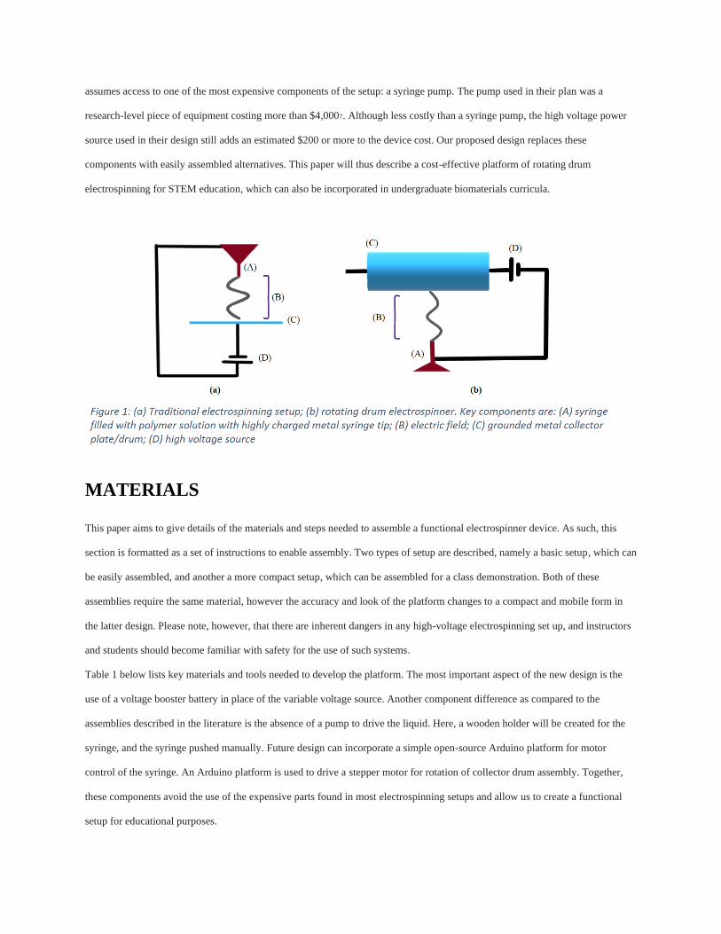
Electrospinning is a method for creating non-woven nanofibers using electric force. This method has been around for more than
100 years, with applications ranging from air filtration to energy storage to tissue engineering1. Electrospinning works by
applying a high voltage (typically between 10 to 20 kV) to the needle of a syringe loaded with a polymer solution. The high
voltage causes the polymer solution to polarize. Beneath the high-voltage needle there is an electrically grounded conductive
collector. The large potential difference between the needle and the collector results in a high-voltage electric field that causes the
polarized solution in the syringe to be drawn toward the collector plate1. Once the electrostatic force overcomes the surface
tension of the liquid, a jet forms in the shape of a Taylor cone and nanofibers are created as the material is pulled off the cone and
drawn toward the collector plate2. Figure 1 shows the basic setup described above in two needle-collector configurations.
In the last 20 years, the field of electrospinning has exploded; in 2000, 17 patents and papers were published related to
electrospinning, while in 2014, over 3,000 articles were published. As of 2015, there were over 50,000 publications in existence
related to the field of electrospinning1. It is thus becoming a mainstay in industry and research. As the field of nanomaterials
continues to establish its prominence and promotes new technology development such as electrospinning, there is a need to
incorporate these developments into secondary (middle and high school) and post-secondary (undergraduate) technology
curriculums, much like 3D printing has made inroads into the classroom in recent years to encourage hands-on learning. These
opportunities provide students hands-on experience and connection to real-world application; both components have proven to
enhance STEM participation3-5.
There is a need for a functional, compact, low-cost electrospinning setup to fulfill the opportunity for advancements in STEM
education. Such a platform can be both used as a classroom tool to demonstrate electrospinning theory and application as well as
offering a hands-on student project opportunity. Velasco Barraza et al. developed what they called a low-cost electrospinning
device for use in bioengineering and biomaterials courses at the undergraduate level6. The device described was low-cost when
compared to commercially available electrospinners, but not in the context of STEM classrooms. For example, the design
assumes access to one of the most expensive components of the setup: a syringe pump. The pump used in their plan was a
research-level piece of equipment costing more than $4,0007. Although less costly than a syringe pump, the high voltage power
source used in their design still adds an estimated $200 or more to the device cost. Our proposed design replaces these
components with easily assembled alternatives. This paper will thus describe a cost-effective platform of rotating drum
electrospinning for STEM education, which can also be incorporated in undergraduate biomaterials curricula.
MATERIALS
This paper aims to give details of the materials and steps needed to assemble a functional electrospinner device. As such, this
section is formatted as a set of instructions to enable assembly. Two types of setup are described, namely a basic setup, which can
be easily assembled, and another a more compact setup, which can be assembled for a class demonstration. Both of these
assemblies require the same material, however the accuracy and look of the platform changes to a compact and mobile form in
the latter design. Please note, however, that there are inherent dangers in any high-voltage electrospinning set up, and instructors
and students should become familiar with safety for the use of such systems.
Table 1 below lists key materials and tools needed to develop the platform. The most important aspect of the new design is the
use of a voltage booster battery in place of the variable voltage source. Another component difference as compared to the
assemblies described in the literature is the absence of a pump to drive the liquid. Here, a wooden holder will be created for the
syringe, and the syringe pushed manually. Future design can incorporate a simple open-source Arduino platform for motor
control of the syringe. An Arduino platform is used to drive a stepper motor for rotation of collector drum assembly. Together,
these components avoid the use of the expensive parts found in most electrospinning setups and allow us to create a functional
setup for educational purposes.
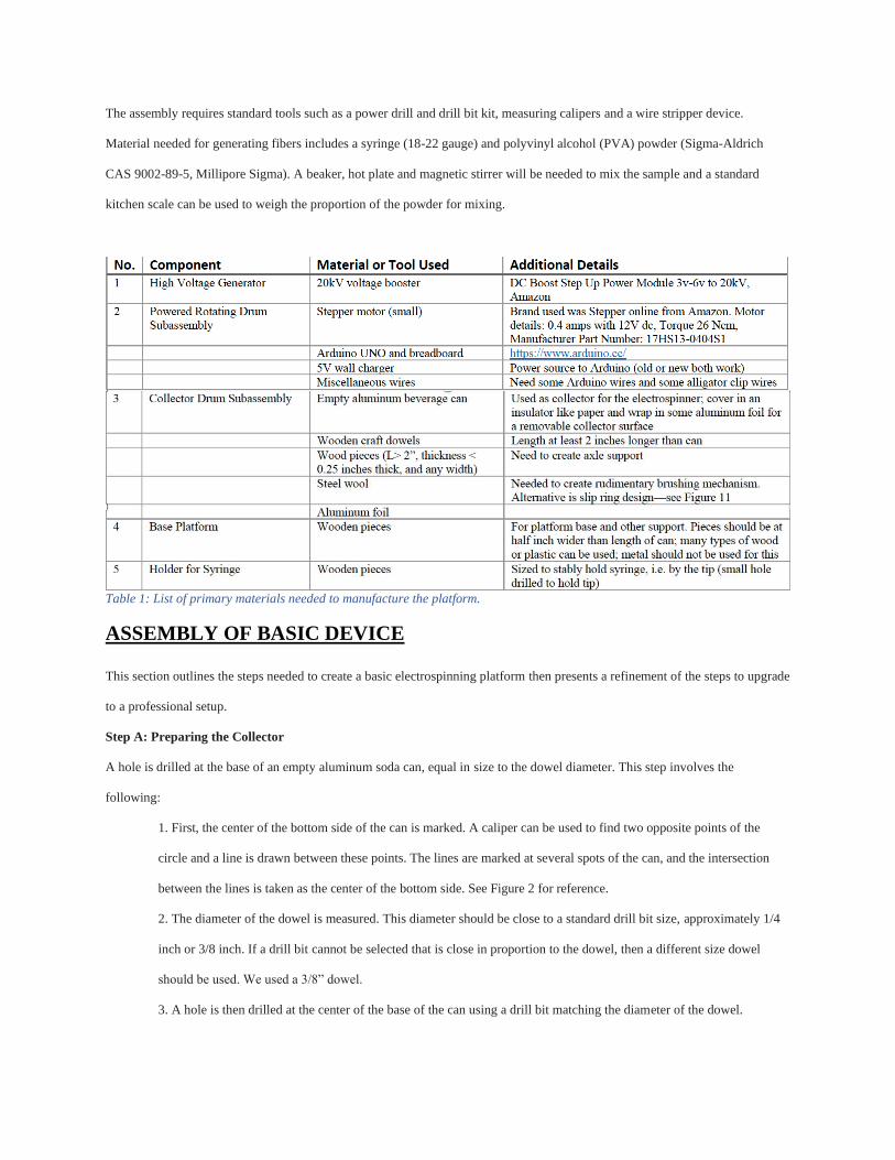
The assembly requires standard tools such as a power drill and drill bit kit, measuring calipers and a wire stripper device.
Material needed for generating fibers includes a syringe (18-22 gauge) and polyvinyl alcohol (PVA) powder (Sigma-Aldrich
CAS 9002-89-5, Millipore Sigma). A beaker, hot plate and magnetic stirrer will be needed to mix the sample and a standard
kitchen scale can be used to weigh the proportion of the powder for mixing.
Table 1: List of primary materials needed to manufacture the platform.
ASSEMBLY OF BASIC DEVICE
This section outlines the steps needed to create a basic electrospinning platform then presents a refinement of the steps to upgrade
to a professional setup.
Step A: Preparing the Collector
A hole is drilled at the base of an empty aluminum soda can, equal in size to the dowel diameter. This step involves the
following:
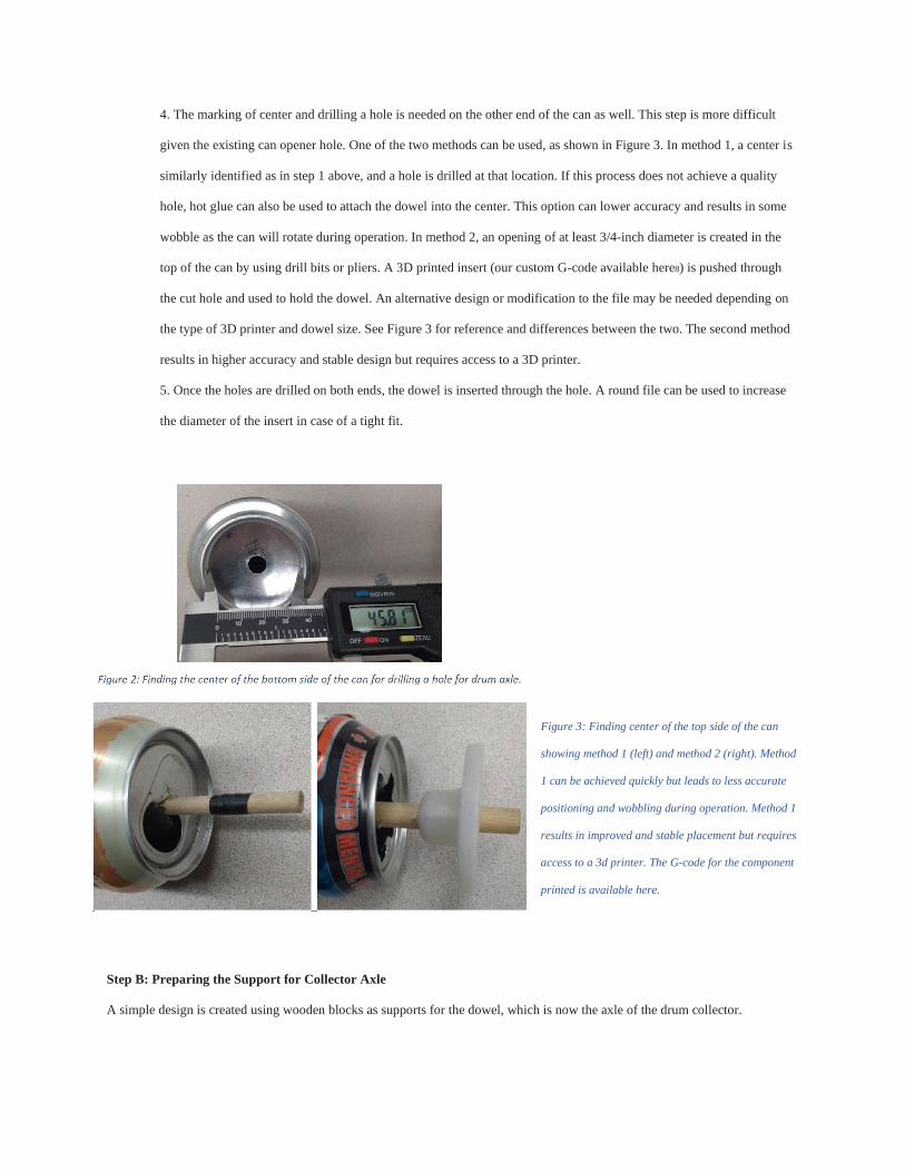
1. First, the center of the bottom side of the can is marked. A caliper can be used to find two opposite points of the
circle and a line is drawn between these points. The lines are marked at several spots of the can, and the intersection
between the lines is taken as the center of the bottom side. See Figure 2 for reference.
2. The diameter of the dowel is measured. This diameter should be close to a standard drill bit size, approximately 1/4
inch or 3/8 inch. If a drill bit cannot be selected that is close in proportion to the dowel, then a different size dowel
should be used. We used a 3/8” dowel.
3. A hole is then drilled at the center of the base of the can using a drill bit matching the diameter of the dowel.
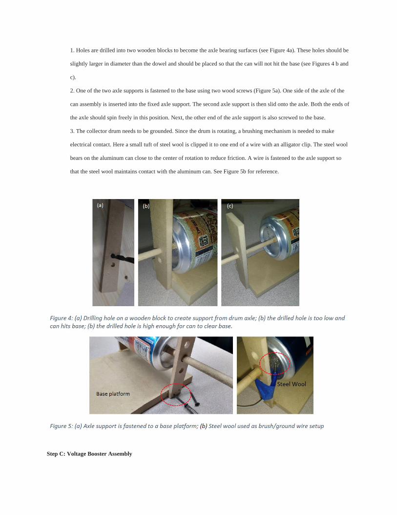
4. The marking of center and drilling a hole is needed on the other end of the can as well. This step is more difficult
given the existing can opener hole. One of the two methods can be used, as shown in Figure 3. In method 1, a center is
similarly identified as in step 1 above, and a hole is drilled at that location. If this process does not achieve a quality
hole, hot glue can also be used to attach the dowel into the center. This option can lower accuracy and results in some
wobble as the can will rotate during operation. In method 2, an opening of at least 3/4-inch diameter is created in the
top of the can by using drill bits or pliers. A 3D printed insert (our custom G-code available here8) is pushed through
the cut hole and used to hold the dowel. An alternative design or modification to the file may be needed depending on
the type of 3D printer and dowel size. See Figure 3 for reference and differences between the two. The second method
results in higher accuracy and stable design but requires access to a 3D printer.
5. Once the holes are drilled on both ends, the dowel is inserted through the hole. A round file can be used to increase
the diameter of the insert in case of a tight fit.
Figure 3: Finding center of the top side of the can
showing method 1 (left) and method 2 (right). Method
1 can be achieved quickly but leads to less accurate
positioning and wobbling during operation. Method 1
results in improved and stable placement but requires
access to a 3d printer. The G-code for the component
printed is available here.
Step B: Preparing the Support for Collector Axle
A simple design is created using wooden blocks as supports for the dowel, which is now the axle of the drum collector.
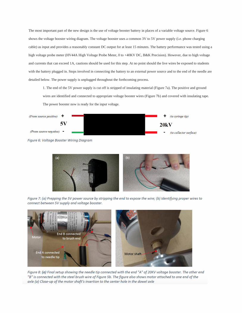
1. Holes are drilled into two wooden blocks to become the axle bearing surfaces (see Figure 4a). These holes should be
slightly larger in diameter than the dowel and should be placed so that the can will not hit the base (see Figures 4 b and
c).
2. One of the two axle supports is fastened to the base using two wood screws (Figure 5a). One side of the axle of the
can assembly is inserted into the fixed axle support. The second axle support is then slid onto the axle. Both the ends of
the axle should spin freely in this position. Next, the other end of the axle support is also screwed to the base.
3. The collector drum needs to be grounded. Since the drum is rotating, a brushing mechanism is needed to make
electrical contact. Here a small tuft of steel wool is clipped it to one end of a wire with an alligator clip. The steel wool
bears on the aluminum can close to the center of rotation to reduce friction. A wire is fastened to the axle support so
that the steel wool maintains contact with the aluminum can. See Figure 5b for reference.
Step C: Voltage Booster Assembly
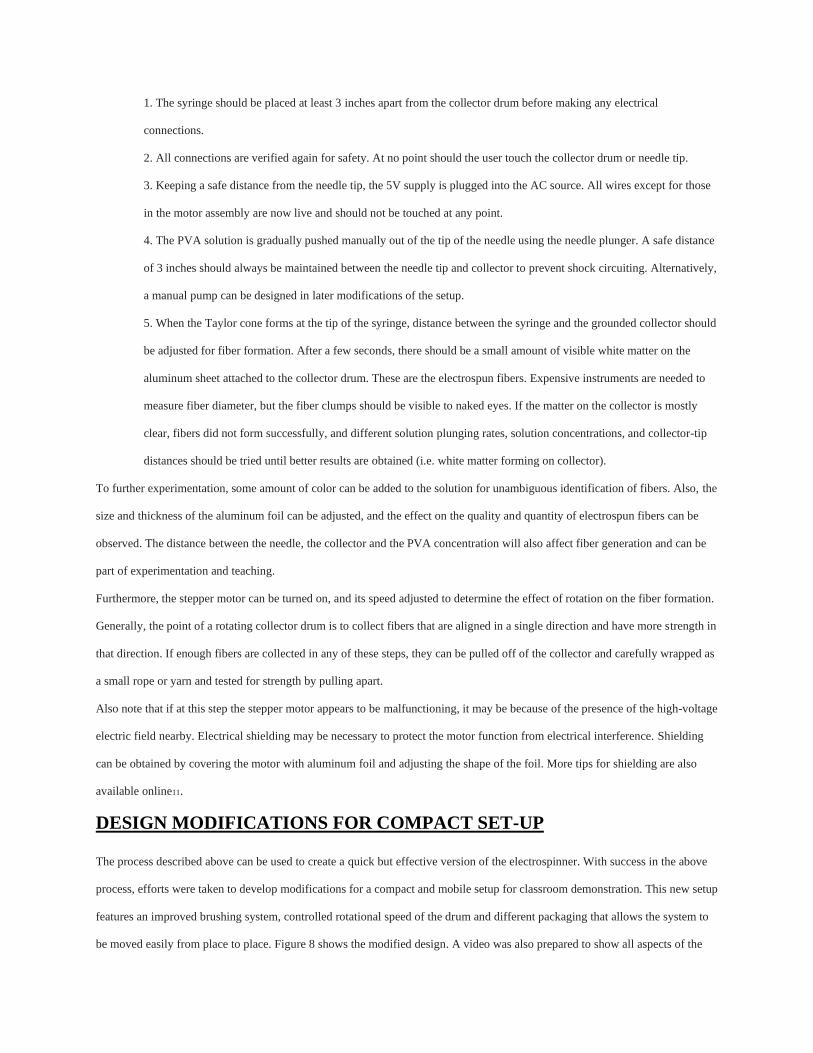
The most important part of the new design is the use of voltage booster battery in places of a variable voltage source. Figure 6
shows the voltage booster wiring diagram. The voltage booster uses a common 3V to 5V power supply (i.e. phone charging
cable) as input and provides a reasonably constant DC output for at least 15 minutes. The battery performance was tested using a
high voltage probe meter (HV44A High Voltage Probe Meter, 0 to +40KV DC, B&K Precision). However, due to high voltage
and currents that can exceed 1A, cautions should be used for this step. At no point should the live wires be exposed to students
with the battery plugged in. Steps involved in connecting the battery to an external power source and to the end of the needle are
detailed below. The power supply is unplugged throughout the forthcoming process.
1. The end of the 5V power supply is cut off is stripped of insulating material (Figure 7a). The positive and ground
wires are identified and connected to appropriate voltage booster wires (Figure 7b) and covered with insulating tape.
The power booster now is ready for the input voltage.

2. On the output side of the voltage booster (20kV side), a wire with alligator clips is fastened to each wire end "A" and
"B." The end “A” is clipped to the metal tip of the syringe, and end “B” is attached with the ground connection of the
steel brush wire of Figure 5b. See Figure 8a for the connections mentioned above.
Step D: Stepper Motor Assembly
A stepper motor is used to connect with the shaft axle to rotate the collector plate. An open-source Arduino platform9 is used for
the motor controls.
1. The stepper motor is connected with the Arduino board using detailed instruction available through Arduino
community10.
2. Once the motor and Arduino are set up, the stepper motor is attached to the rotating drum (see Figure 8b). To attach
the drum, a hole is made equal in diameter to the stepper motor shaft on one end of the dowel opposite to which the
steel wool is attached. The hole should be carefully prepared at the center of the dowel. Alternatively, a lathe machine
can be used for accuracy if available.
3. The shaft of the stepper motor is next inserted into this hole, making sure that fits tightly. If not, hot glue may be
used to keep it well-affixed to the dowel. The motor body is fixed in place by drilling holes into the end of the shaft
support and using two screws. Alternatively, hot glue can also be used. Small wood spacers or washers may be needed
between the motor mounts and the axle support to allow for proper placement.
Step E: Preparing the Solution and Collector Drum Area
Before connecting the wires, the solution to be inserted into the needle should be prepared. Here we use PVA and water to make
the solution. Varying PVA to water ratios can be used and adjusted to yield appropriate fiber diameters. Here we prepared the
solution in ratios between 15 and 25%. The powder water mixture is heated and continuously stirred during preparation. We used
a hot plate heated at 800 C, mixed with a magnetic stirrer. A consistent homogenous mixture is obtained after an hour. As the
solution cools, it is placed inside the syringe.
To further experimentation and for ease of fiber removal from the collector, the collector is wrapped with conductive aluminum
foil. The conductive area of the collector drum can be adjusted by wrapping the collector first with an insulator like paper, then
wrapping it with foil on a smaller portion of the surface (see Figure 7a). Here we used several layers of paper as an insulator. An
auxiliary ground wire will need to be placed to connect the grounded can to the aluminum foil if the area is adjusted.
Step F: Starting up the Device and Fiber Generation
At the end of step E, the device will be ready for experimentation. All electrical connection should be checked for safety. No
wires should be exposed. Use electrical tape as needed to tape the wire ends and attach any loose wires to the platform. All safety
precautions should be followed before moving to the next step.
1. The syringe should be placed at least 3 inches apart from the collector drum before making any electrical
connections.
2. All connections are verified again for safety. At no point should the user touch the collector drum or needle tip.
3. Keeping a safe distance from the needle tip, the 5V supply is plugged into the AC source. All wires except for those
in the motor assembly are now live and should not be touched at any point.
4. The PVA solution is gradually pushed manually out of the tip of the needle using the needle plunger. A safe distance
of 3 inches should always be maintained between the needle tip and collector to prevent shock circuiting. Alternatively,
a manual pump can be designed in later modifications of the setup.
5. When the Taylor cone forms at the tip of the syringe, distance between the syringe and the grounded collector should
be adjusted for fiber formation. After a few seconds, there should be a small amount of visible white matter on the
aluminum sheet attached to the collector drum. These are the electrospun fibers. Expensive instruments are needed to
measure fiber diameter, but the fiber clumps should be visible to naked eyes. If the matter on the collector is mostly
clear, fibers did not form successfully, and different solution plunging rates, solution concentrations, and collector-tip
distances should be tried until better results are obtained (i.e. white matter forming on collector).
To further experimentation, some amount of color can be added to the solution for unambiguous identification of fibers. Also, the
size and thickness of the aluminum foil can be adjusted, and the effect on the quality and quantity of electrospun fibers can be
observed. The distance between the needle, the collector and the PVA concentration will also affect fiber generation and can be
part of experimentation and teaching.
Furthermore, the stepper motor can be turned on, and its speed adjusted to determine the effect of rotation on the fiber formation.
Generally, the point of a rotating collector drum is to collect fibers that are aligned in a single direction and have more strength in
that direction. If enough fibers are collected in any of these steps, they can be pulled off of the collector and carefully wrapped as
a small rope or yarn and tested for strength by pulling apart.
Also note that if at this step the stepper motor appears to be malfunctioning, it may be because of the presence of the high-voltage
electric field nearby. Electrical shielding may be necessary to protect the motor function from electrical interference. Shielding
can be obtained by covering the motor with aluminum foil and adjusting the shape of the foil. More tips for shielding are also
available online11.
DESIGN MODIFICATIONS FOR COMPACT SET-UP
The process described above can be used to create a quick but effective version of the electrospinner. With success in the above
process, efforts were taken to develop modifications for a compact and mobile setup for classroom demonstration. This new setup
features an improved brushing system, controlled rotational speed of the drum and different packaging that allows the system to
be moved easily from place to place. Figure 8 shows the modified design. A video was also prepared to show all aspects of the

modified device which can be accessed here: https://youtu.be/iJZ2oGCSuzo. The section below briefly summarizes the key
changes.
Improved Brushing System
The improved brushing system on the device uses a slip ring (Comidox 12.5mm Capsule Electrical Slip Ring, Amazon) that
allows a wire to be passed from a rotating component to a stationary one. The previously described device used a homemade
brush using steel wool. The new system uses a professionally made brushing device. Since only one wire was needed to ground
the aluminum foil placed on the rotating drum, the extra slip ring input and output wires were tucked out of the way of rotating
components. Alternatively, they could have been cut off, or multiple wires could have been attached as ground wires (i.e.
increase conducting cross-sectional area). Using only one wire in this setup did not appear to hinder electrospinning performance.
Controlled Rotational Speed
A standard small stepper motor from an Arduino kit was used to provide a controllable rotational velocity of the drum setup. The
details necessary to set up and code this type of stepper motor with Arduino UNO microcontroller, potentiometer control and its
included stepper are readily available, and hence no further details are provided here.
Improved Device Packaging
To have a device that effectively allows the electrospinning concepts to be taught and demonstrated in various settings, the device
must be easy to move from place to place. A mounting box was created so that while some components (ex: syringe, speed
adjusting knob) were easily accessible for user interaction, other components (ex: Arduino microcontroller, voltage booster,
breadboard) were tucked out of the way on the inside of the box. The new setup requires two USB plugs to turn the system on
and off: one for the stepper motor and one for the high voltage boosting assembly. Overall, the above adjustment makes it easy to
unplug the entire electrospinning device, move it to an educational venue for demonstration and plug it in there using simple
USB ports. Two mounts were also created from wood to mount the syringe while demonstrating the operation of the device.
RESULTS
Cost Comparison with Standard Electrospinner
With low cost being one of the critical features of this device, it is essential to provide a breakdown of the equipment expenses.
The primary cost savings comes from the use of an inexpensive high voltage booster and the exclusion of the costly syringe
pump. The total cost of the step was $60, with the breakdown given below.
• $10 High Voltage Booster
• $8 Slip Ring
• $10 Wood and Plastic Materials
• $9 Arduino UNO
• $8 Stepper Motor and Driver
• $7 5V AC adapter for Voltage Booster Supply (or Old Phone Charging Cord)
• $3 Various Connecting Wires
• $0 Used Pop Can
• $5 Syringe
When compared with the least expensive devices found online and device described in Velasco Barraza et al., this device is an
estimated 95–98% less costly when considering all the components in the final setup3. Even excluding syringe pump cost-saving,
the device described here would still save at least 50%, if not much more, due to the use of the $10 voltage booster device. This
price analysis does not include the cost of creating the PVA solution used to electrospin fibers, as that cost would be consistent
across devices.
Fiber Formation and Student Demonstration
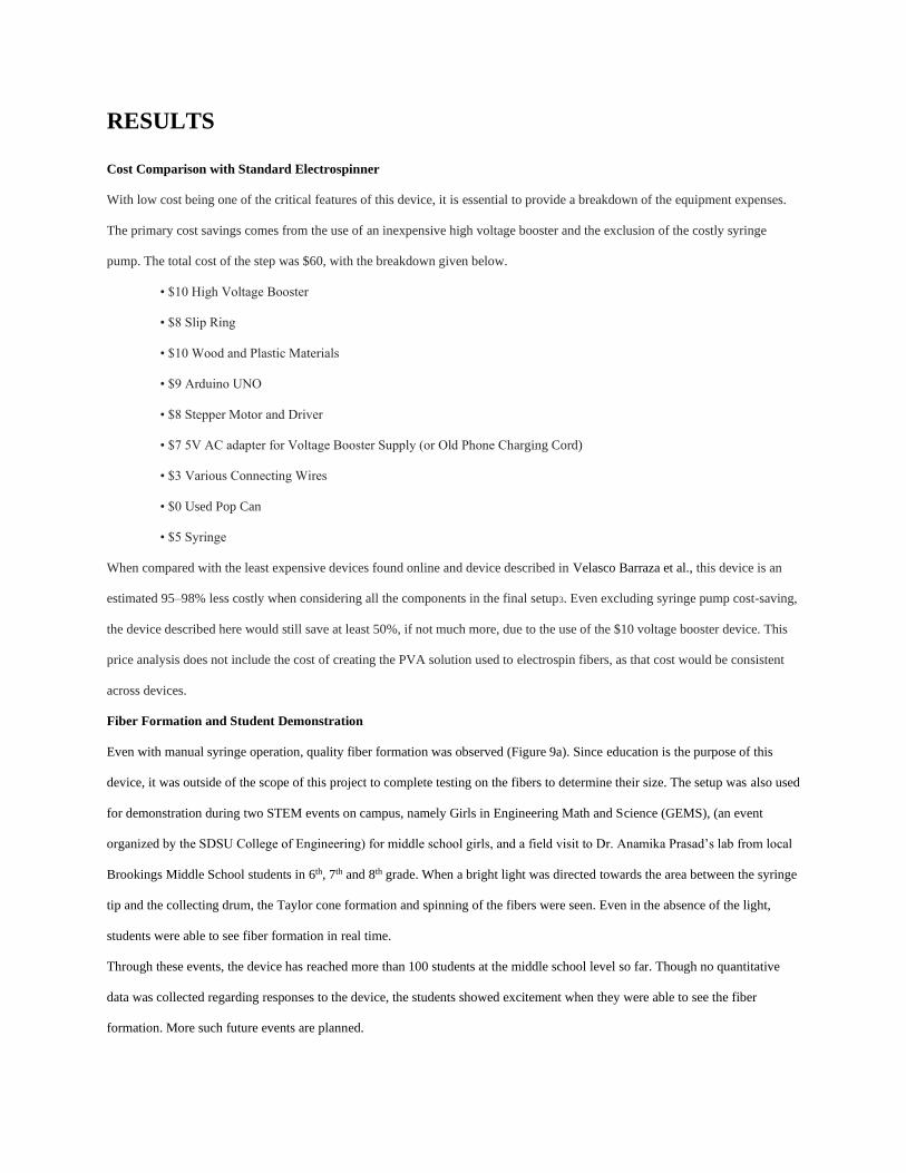
Even with manual syringe operation, quality fiber formation was observed (Figure 9a). Since education is the purpose of this
device, it was outside of the scope of this project to complete testing on the fibers to determine their size. The setup was also used
for demonstration during two STEM events on campus, namely Girls in Engineering Math and Science (GEMS), (an event
organized by the SDSU College of Engineering) for middle school girls, and a field visit to Dr. Anamika Prasad’s lab from local
Brookings Middle School students in 6th, 7th and 8th grade. When a bright light was directed towards the area between the syringe
tip and the collecting drum, the Taylor cone formation and spinning of the fibers were seen. Even in the absence of the light,
students were able to see fiber formation in real time.
Through these events, the device has reached more than 100 students at the middle school level so far. Though no quantitative
data was collected regarding responses to the device, the students showed excitement when they were able to see the fiber
formation. More such future events are planned.
CONCLUSION
This paper describes the design and assembly of a basic and compact mobile version of an electrospinner. The device can be
assembled at a cost of $60, which is a fraction of the $4,000+ price tag of basic electrospinners demonstrated in existing
literature. The cost-saving was made possible primarily because of the use of a voltage booster, which effectively maintained a
high voltage of 8kV-10kV over the course of 15 minutes of testing, which was a sufficient amount of time to demonstrate the
device. The setup was also shown to be useful for STEM education demonstration purposes. It was used to demonstrate
electrospinning technology to middle school students during STEM outreach events on campus. Seeing the formation of
nanofibers in real-time actively engaged the students. Future work will focus both on design modification, the primary being
addition of a custom-built low-cost syringe pumping device, as well as outreach via STEM events and data collection of that
outreach.
REFERENCE LIST
1. Li, H. and Yang, W., 2016. Electrospinning Technology in Non-Woven Fabric Manufacturing. Non-woven
Fabrics. IntechOpen.
2. Sill, T., and von Recum, H. Electrospinning: Applications in drug delivery and tissue engineering. Biomaterials.
2008: 29(13): 1989-2006.
3. Ferreira, M. M. & Trudel, A. R. The Impact of Problem-Based Learning (PBL) on Student AttitudesToward
Science, Problem-Solving Skills, and Sense of Community in the Classroom. J. Classr.Interact. Houst. 47, 23–
30 (2012).
4. Balasubramanian, N., Wilson, B. & Cios, K. J. Innovative Methods of Teaching and Learning Science and
Engineering in Middle Schools.
5. Merritt, J., Lee, M. Y., Rillero, P. & Kinach, B. M. Problem-Based Learning in K–8 Mathematics and Science
Education: A Literature Review. Interdiscip. J. Probl.-Based Learn. 11, (2017).
6. Velasco Barraza, R.D. et el. Designing a Low Cost Electrospinning Device for Practical Learning in a
Bioengineering Biomaterials Course. Revista Mexicana de Ingeniería Biomédica. 2016; 37910: 7-16.
7. Wpiinc.com. Two-Syringe Push-Pull Pump. Available at: https://www.wpiinc.com/var-3432-two-syringe-pushpull-
pump? [Accessed 29 Aug. 2019].
8. G-Code available at https://grabcad.com/library/pop-can-centering-insert-g-code-1
9. Arduino available at https://www.arduino.cc/
10. Stepper Motor control and Arduino, available at https://www.arduino.cc/en/Tutorial/StepperSpeedControl
11. Electrical shielding, available at https://electronics.stackexchange.com/questions/164034/how-to-shield-forelectromagnetic-
interference-diy-level