Embed Size (px)
Citation preview
DESIGN OF AN ELECTRIC LIGHTING SYSTEM FOR
CAMDEN, INDIANA
BY
ALBERT PENN
THESIS FOR THE DEGREE OF BACHELOR OF SCIENCE
IN ELECTRICAL ENGINEERING
IN THE
COLLEGE OF ENGINEERING
OF THE
UNIVERSITY OF ILLINOIS
Presented June, 1909
brought to you by COREView metadata, citation and similar papers at core.ac.uk
provided by Illinois Digital Environment for Access to Learning and Scholarship Repository
I W
UNIVERSITY OF ILLINOIS
June 1, 1909
THIS IS TO CERTIFY THAT THE THESIS PREPARED UNDER MY SUPERVISION BY
........................................................ALBERT...PENN ............ ............ .................... ........................
ENTITLED DESIGN OP..AN ELECTRIC LIGHTING SYSTEM..EQR.. IL L IN O IS
IS APPROVED BY ME AS FULFILLING THIS PART OF THE REQUIREMENTS FOR THE
degree QF-Baohelor of soienoe in Eleotrioal Engineering
head of department OFElectiMcal Engineering
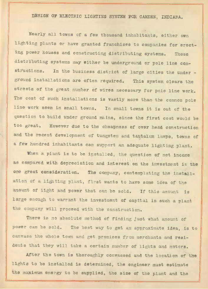
DESIGN OP ELECTRIC LIGHTING SYSTEM EOR CAMDEN, INDIANA.
Nearly a ll towns of a few thousand inhabitants, either own lighting plants or have granted franchises to companies for erecting power houses and constructing distributing systems. These distributing systems may either be underground or pole line constructions. In the business d istrict of large c it ie s the under -ground installations are often required. This system clears the
.
streets o f the great number of wires necessary for pole line work. The cost of such installations is vastly more than the common pole line work seen in small towns. In small towns it is out of the question to build under ground mains, since the f ir s t cost would be too g^eat. Hov/ever due to the cheapness of over head construction and the recent development of tungsten and tautalum lamps, towns of a few hundred inhabitants can support an adequate lighting plant.
When a plant is to be installed, the question of net income as compared with depreciation and interest on the investment is the one great consideration. The company, contemplating the in sta llation of a lighting plant, f ir s t wants to have some idea of the amount of light and power that can be sold. I f this amount is large enough to warrant the investment of capital in such a plant the company w ill proceed with the construction.
There is no absolute method of finding just what amount of power can be sold. The best way to get an approximate idea, is to canvass the whole town and get promises from merchants and residents that they w ill take a certain number of lights and motors.
After the town is thoroughly convassed and the location of the lights to he installed is determined, the engineer must estimate the maximum energy to he supplied, the size of the plant and the

(2)
most economical location for such, a plamt.It is found from experience that about one-fourth the number
of lights installed in residences w ill be the maximum number in use at any one time. In the stores it is safe to assume that the maximum load w ill be a ll the lights. The street lighting w ill require a constant amount of energy. This gives a method of finding the capacity of the station. The time of day and duration of maximum load can be roughly estimated. All the stores are usually open from five to eight in the evening. Thus in the winter time,tnis w ill be the time of maximum load for the business houses. Also the maximum residence lights w ill be in use about this time.
I f the supper hour is six o 'clock the wife w ill have the lamps in the kitchen and dinning room burning. One or more lamps might be burning in a sitting room for reading purposes. All things considered we believe that one-fourth the number of lights in sta lled w ill be a fa ir estimate of the maximum residence load.
There are two possible systems of e lectr ic lighting, direct and alternating current. I f power is to be sold for motor work it is almost compulsory to install D. C. Machinery. Where direct current is used for lighting the voltage must be maintained at a- ? bout 110 volts, or whatever the lighting voltage may be. This requires an enormous expense in line copper i f the distance be very great, since the wire must be large enough to carry the maximum load with less than 4 °/0 drop. The only saving over A.C. is the cost of transformers. In the A.C. system the distributing vo ltage may be made high so that the line wire w ill be reduced to a small size and thus the cost. The added expense w ill be the transformers. This cost is small compared to the extra copper cost for

(3)
D.u* work. Thus A.O, distribution is to be chosen where l i t t l e or no motor work is to be found. In this design the A.C, system has been chosen since a ll the power used w ill be for lighting purposes.
Having located the lamps and estimated the maximum load, it remains to find the size of the wire necessary to carry such a load from the transformer to the different lamps. The location of transformers, w ill of course, a ffect the distances. It is desirable to place the transformers in some central position so as to supply as large a territory as possible. The size of wire to be chosen is that which w ill not have more than a certain allowable drop, to the last lamp, when the maximum load is on. For 110 volt lamps the regulation is 4 to 5 volts or about 4 ° /o . Thus thedrop to the last lamp of 100 uniformily distributed lamps w ill depend upon the distance, size of wire and amount of current taken by each lamp. Suppose the high efficiency tungsten lamp, each taking .25 amperes be considered. Suppose the distance to the last lamp to be 400 fee t. Since there are 100 lamps each taking .25 amperes the tota l current to the f ir s t lamp w ill be 25 amperes. Through the last lamp there is .25 amperes flowing. Thus the av
erage current is ~̂~2= 12,625 amperes, for 400 feet. I f No.6 wire be used the maximum drop may be calculated as follows
No. 6 has a resistance per 1000 feet of .394 ohms. Since thedistance is 400 feet to the last lamp the total length of wire w illbe 800 fee t,
800T000' x .394 = ,315 ohms resistance for 800 feet.drop = E x I.315 x 12.625 = 3-9 volts drop.
Since th is is le s 3 than the allowable drop of 4 °/o 6 wire may

(4)
be used.A like method is used for calculating the size of high tension
wires.
The problem of e lectr ic lighting of small towns, has come to be a more tangible subject, since the invention and placing on the market of tungsten lamps. This lamp requires only about one-third the current, at the same voltage to give candle power equal to the carbon filament lamps. The l i f e of the tungsten lamp is about 800 hours as compared to 400 for the carbon lamps.
To produce 16 candle power with a carbon filament lamp it requires .5 amperes at 110 volts . To produce 16 candle power with the tungsten lamp requires .166 amperes at 110 volts. Thus the watts per candle are one-third for the tungsten as for the carbon filament lamp. Also the l i f e of the tungsten is twice as long which means that the lamp is six times as economical after f ir s t cost.
The carbon lamp costs about 20/ each for a 16 candle power size while the tungsten costs about 85 cents each. Suppose a carbon lamp is burned 800 hours. It would require a renewal, thus f ir s t cost would be 40 cents.
fThe watts consumed equal .5 x 110 = 55«
800 x 55 = 44000 watt hrs.= 44 K. W. hrs.
At 15 / per K. W. hr.44 x 15 / = #6.60 cost of energy6.60 + 40 = $7,00 tota l cost for 800 hrs.
Suppose a tungsten lamp be burned for the same length time. First
cost would equal 85/
(5)
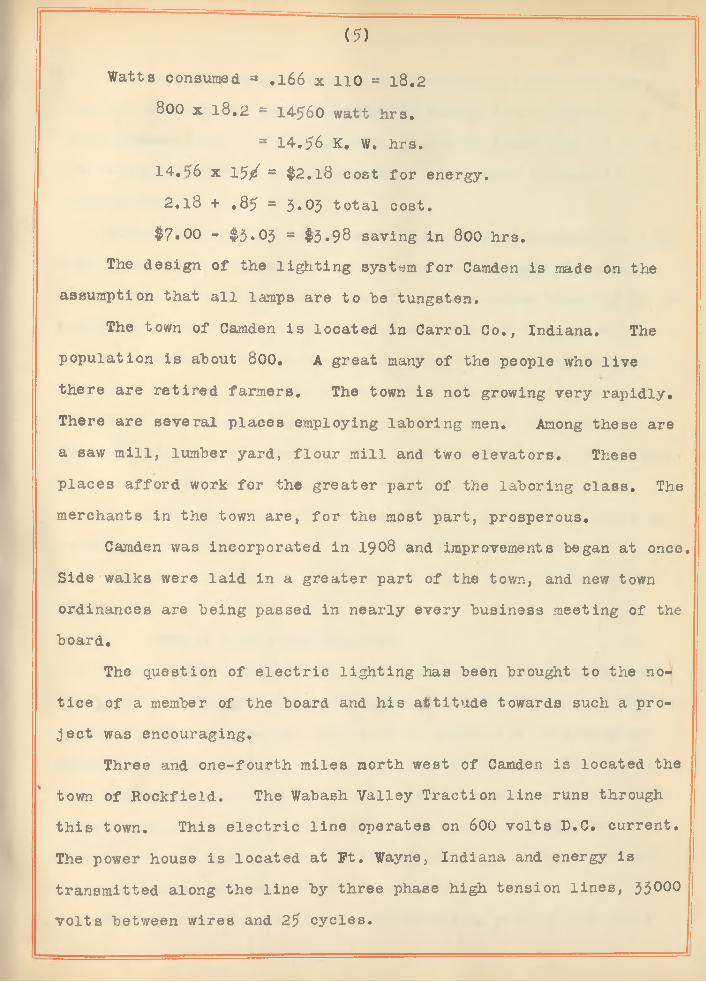
Watts consumed = .166 x 110 = 18.2
800 x 18.2 = 14560 watt hrs.= 14.56 K, W. hrs.
14, >6 x 15 / = #2.18 cost for energy.2, l 8 + .85 = 5»05 tota l cost.
$7*00 - $3*03 = $>3*98 saving in 800 hrs.The design of the lighting system for Camden is made on the
assumption that a ll lamps are to "be tungsten.The town of Camden is located in Carrol Co., Indiana. The
population is about 800. A great many of the people who live there are retired farmers. The town is not growing very rapidly. There are several places employing laboring men. Among these are a saw m ill, lumber yard, flour mill and two elevators. These places afford work for the greater part of the laboring class. The merchants in the town are, for the most part, prosperous.
Camden was incorporated in 1908 and improvements began at once. Side walks were la id in a greater part of the town, and new town ordinances are being passed in nearly every business meeting of the board.
The question of e lectr ic lighting has been brought to the notice of a member of the board and his attitude towards such a proje c t was encouraging.
Three and one-fourth miles north west of Camden is located the town of Hockfield. The Wabash Valley Traction line runs through this town. This e lectr ic line operates on 600 volts D.C. current. The power house is located at Ft. Wayne, Indiana and energy is transmitted along the line by three phase high tension lines, 33000
volts between wires and 25 cycles.

(6)
The design is calculated for a purchase of power from this traction company, to "be transmitted to Camden from Rockfield by three phase lin es. A transformer, placed at Rockfield, is to step the voltage down to about 22,65 volts. The exact voltage is calculated later.
Since 25 cycles is not a very satisfactory frequency for light- ing, a frequency changer, located at Camden, changes the alternations from 25 to 50 cycles. The frequency changer consists of two machines connected together on the same axle. One machine is a two pole machine and operates bn the high tension 25 cycle side.The other machine is a similar four pole alternator. Thus the frequency of the alternations in the second machine is 50 cycles.These machines were chosen in order to reduce the sizes that would be necessary to change from 25 to 60 cycles.
It has been the aim in this design to estimate as closely as possible the amount of power that would be used and the cost.Over against this cost is balanced the income and profits to the c ompany.
INSIDE LIGHTS AND LOCATION.In any house, of ordinary size, the lights may be estimated *
pretty closely by assuming certain numbers for each room. Thus in a house of eight rooms, we fee l safe in making the following assumptions : One light on porch, one in front hall, three in sitting,room, two in dining room, two in kitchen, one in each of the other rooms, making a total of 14. Of course only a few of these will be turned on at any one time. As has been said before, perhaps only one-fourth of them w ill be in use at once.
Beginning at the Baptist Church and going west on the south

(7)
side of Main Street the number of lamps are estimated as given
below.
Baptist Church
Baptist Parsonage -
Dr. H all's Residence —
Dr. H all's Office .................................................... *Restaurant c-
Tin s h o p ....................................................................... ...
Grocery Store 14
Grocery Store . . . . . . . . . . . . . . _ _ 14
McFarland's Store - - - - - - - - - . - - . - 2 0
Fanner's Bank . . . . . . . . . . . . . . . . 3
Armick's Drug Store - - - - - . - - - - - . . 1 0
Hardware . . . . . . . . . . . . . . . . . . . 10
Bank 3
R i c e 's Residence - - - - - - - - - - - - - - - 20
Baker's Residence - - - - - - - - - - - - - - 1 5
Hotel - - . - 2 0
Store 3
Hotel . - . . - - - - . . . - - . . . . . . . 1 4
Telephone Exchange - - - - - - - - - - - - - - 1 0
Sieber' s Residence - - - - - - - - - - - - - - 1 8
Other houses on south side - - - - - - - - - - 1 0
On the north side of vain Street the following number of lamps w ill
approximate the number i n s t i l l e d .
Blue's Residence
Rea dence - - -
Residence
16
88

(8)
Cornell's Residence - - - - - - - - - - - - - 12
SnyderRe si. dence - - - - - -Residence £Ray's Residence - - - - - - - - - - - - - - - 14
Masonic Temple - - - - - - - - - - - - - - - - 80
Resdence - - _ _ - 10
Residence - - - - - - - - - - - - - - - - - - 14
Residence - - - - - - - - - - - - - - - - . . 1 4
Residence - - - - - - - - - - - - - - - - - - 15
Residence - - - - - - - - - - - - - - - - - - 2̂
South of Main on MonroeM. E, Church - - - - - - - - - - - - - - - - - 24Residence near - - - - - - - - - - - - - - - - 20
South on Main on WaterOpera House - - - - - - - - - - - - - - - - - 3 8
North of Main Street on Water Street.Residences f ir s t block - - - - - - - - - - - - 4 0
On Cumberland StreetResidences - - - - - - - - - - - - - - - - - -150
Luthern Church - - - - - - - - - - - - - - - - 4 0On Washington Street.
Assuming an average of five per house - - - -125 East end of town: Main street, North side.
Tesh's Residences - - - - - - - - - - - - - - 1 6
Scholl's Residence - - - - - - - - - - - - - - 1 8
Wharton's Residence - - - - - - - - - - - - - 1 2Other residences - - - - - - - - - - - - - - - 60
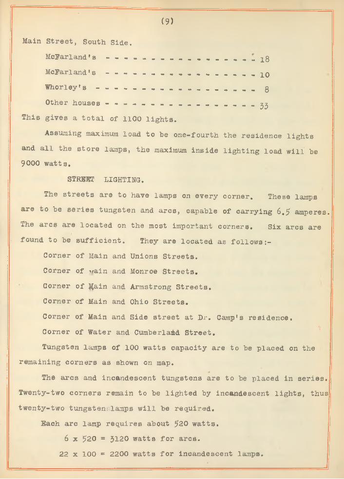
Main Street, South Side. McFarland's - - - McFarland *s - - -
(9)
- 18
- 10Whorley's gOther houses - ^
This gives a tota l of 1100 ligh ts.
Assuming maximum load to be one-fourth the residence lights and a ll the store lamps, the maximum inside lighting load w ill be 9000 watts.
STREET LIGHTING.
The streets are to have lamps on every corner. These lamps are to be series tungsten and arcs, capable of carrying 6.5 amperes. The arcs are located on the most important corners. Six arcs are found to be su ffic ien t. They are located as fo llow s:-
Corner of Main and Unions Streets.Corner of vain and Monroe Streets.Corner of |$ain and Armstrong Streets.Corner of Main and Ohio Streets.Corner of Main and Side street at Dr. Camp's residence.
i,Corner of Water and Cumberland Street.Tungsten lamps of 100 watts capacity are to be placed on the
remaining corners as shown on map.The arcs and incandescent tungstens are to be placed in series.
Twenty-two corners remain to be lighted by incandescent lights, thus twenty-two tungsten; lamps w ill be required.
Each arc lamp requires about 520 watts.6 x 520 = 3120 watts for arcs.
22 x 100 = 2200 watts for incandescent lamps.

(10)
3120 + 2200 = 5320 total energy for street lighting.9000 watts = maximum energy for inside lighting,9000 + 5320 = 14320 total watts to he transmitted.The distributing voltage used in most towns, is 23OO at the
station. Higher voltage is thought to he too dangerous and areprohibited by ordinances of the town boards. I f now the line dropbe 100 volts-the voltage at the transformers w ill be 2200. Thastandard ra tio of transformation to 10 to 1 and 20 to 1 . Thus for volt110A lamps, standard transformers can be used. In this design it is desired to have standard transformers to step the voltage down to 220 & 110 from the high tension lines.
The voltage between wires, on the three phase A. C. transmission lines of the traction company, is 33OOO. Since the distance to Camden is short and the energy to be transmitted is small i t is thought best to step the voltage down to 2300 volts at Rock- f ie ld and transmit to Camden. This does away with the danger of such high voltage and also lessens the cost of insulators used on the transmission lin e . The capacity of this transformer is to be 20.8 K. W.
No. 6 ,wire is the smallest wire commonly used for pole line work since it requires about this size for mechanical strength.
Having decided upon the size of the transmission wire it remains to find the line drop and the size of the distributing transformers.
Where the load is heavy it w ill a ffect a saving of copper of a three wire 220 volt system be used. In the business d istrict it was found economical to install this distributing system.
No. 6 wire has a resistance per 1000 feet of .394 ohms. I f

(11)
resistance alone affected the drop it would be quite a simple calculation, but in alternating current circu its the inductances of whe lines enter into the question of voltage drop* Also the distance between the lines must be considered. By referring toCrockers E lectric Lighting, page 130, the inductance for No, 6 wire
.lo inches apart is found to be 1.82 millibenrys per mile. This equals .0059 benrys for 3.25 miles. The reactances due to inductance =2 v f L.
w = 3.14f = 25L = .0059
Reactance = .925
Impedance *= VR2 + X2 = 6.76 ohms.Since R = resistance = 6.7 ohms, and X = reactance = .925
To find the drop in the lines it is necessary to find the current flowing.
The different transformers w ill not be loaded equally but the transmission lines from Rockfield to the frequency changer w ill always have a balanced load. I f the maximum load be 15 K. W. the energy to be transmitted over the lines w ill be 15 K. W. plus the losses.
Assuming a loss of 20 per cent in the frequency changer, 4 per cent for the- transformers and 1 per cent for the distributing lines the energy to be transmitted w ill be 20 K. W.
The frequency changer operates on 2200 volts and delivers cur- rent to the distributing mains at a voltage slightly above 2200, to compensate for transformer loss and line drop.
....................... — .. - —- J

( 12)
I f 20 K. W. are to be transmitted over three lines, each linemust furnish one-third of the energy or 6.7 K. W. The voltage between wires is 2200, thus the voltage between any line and the neu-
2200tral is ~ 1270 vo lts .I a watt s
E_ 6700
1270
- 5o amperes Drop on each line = I Z
Where 2 = impedance 5.3 x 6.76 = 36 volts.
This is the drop between each line and the neutral. To find the drop between wires.it is necessary to multiply by \/3 •
36 x ^ = 62 vo lts .z z 000Thus the ratio of transformation at Rockfield should be
2265 x \ZT x 5.3 = 20800 watts. Thus transformer capacity w ill be 20.8 K. W.
For the street lighting service arcs and incandescents are to be used carrying 6.5 amperes. The tota l watts as calculated before is 5320. = 8l5 volt s necessary to impress upon the mains.A constant current transformer is to be used in this circu it and can be regulated to give the required voltage.
The location of the distributing transformers is determined by the location of the lamps to be supplied. For supplying the north-west part of town a transformer is located at the corner of Cumberland and the church streets. This transformer is to supply
■ {energy for a ll inside lights north of main street and west including Water Street. The distributing mains are shown on map in broken lin es.

( 13)
The maximum power required for this part of town is estimated at about 2200 watts. I f we assume 2200 volts across the primary at the transformers, the current in the primaries is found from the following ra tios:
I ' = E"I" E'
WattsT il = ............. —Voltage
2200= 110
~ 20 amperes in secondaryThus I ' 20 x 110
2200 '
= 1 amperes in primaryAssuming .96 per cent efficien cy the primary current = 1.04 amperes.
Since the distance to th is transformer is short the inductance of the lines may he neglected. Resistance to transformer = .85
ohms..85 x 1.04 = .9 volts line drop.
This is too small to consider. By the excitation of the frequency changer the voltage may he varied to suit the load.
The lights on the transformer in the east part of town are to he supplied with energy from the same phase. This makes 3300 watts on this phase and aids in balancing the system.
ligh ts on Main Street and south of same are to he supplied with power from the third phase. By the estimate already made of the maximum load, it is found to he about 5900 watts. Thus the transformer must, he a 5 K. W. transformer. By placing this transformer at the alley between Water and Monroe streets the distribution east and west w ill he nearly equal. By using a three wire 220 vo lt, distributing system the amount of copper w ill he greatly re-

(14)
duced.
The rating of the distributing transformers is as follow s:For Northwest portion of town
Primary voltage 2200 Secondary voltage HOSecondary current 20
Primary current l .For East portion of town
Primary voltage 2200 Secondary voltage HO Secondary current io amperesPrimary current .5 amperes
For transformer in business portion.Primary voltage 2200 Secondary voltage 220
Secondary current 26.8 amperesPrimary current 2.68 amperes
For the constant current transformer for street lighting the rating is :
Primary voltage 2200Secondary voltage 860
Secondary current 6.5Primary current 1.66
POLE LINE CONSTRUCTION.No, 6 wire is as small a wire as is thought wise to string on
account of the mechanical strength required. I f the poles be placed 120 feet a part i t w ill require 14-5. Of course a few extra poles w ill be required on curves and corners. This fact being considered,

(15)
it is estimated that 156 poles w ill be su ffic ien t. These poles are to be 25 feet long with a top diameter of 5 inches. This number of poles is required to bring the high tension wires to a switch house located at the corner of Water and Washington streets.
The wires used are to be bars n°» 6 and placed upon a cross arm 2 -l/2 feet long. Cross-arms are to be made of pine 2 -l /2 feet X 4 -l/4 inches X $-l/4 inches. Each cross arm is to be fastened to the pole with two bolts and two braces 20 inches long. All fastenings to be made with bolts. Where the surface is wood, washers are to be used. The insulators are to be extra D. G. D. P. glass.
SWITCH HOUSE
In th is switch house w ill be placed the frequency changer, D.C. exciter, switch board and constant current transformer for series street lighting. The arrangement of the machinery is shown on the plan, plate No. I . The wiring diagram for the switch-board is shown in plate II .
By closing switches No. I and 2 the power is on the d is tr ibuting transformers and the inside lights may be used. Switch Nc.3, when closed, turns on the street lights. It is necessary to have house lights before the street lights are in use.
POLE LINES IN TOWNThe poles are to be the same as above and placed three to a
block. This makes them about 125 feet apart. Cross-arms to be the same, with a minimum distance of 6 inches between the wires.
STREET LIGHTING.The street lights are to consist of six arcs and twenty-two
incandescent. There are to be suspended in the middle of the street. A "running pulley ou tfit" , for the arcs and an "always

( 16)
level o u tfit” for the incandescents. The wire used is to be No. 6
B & S Weather proof. This wire is strung on the poles erected for inside lignting mains, whereever it is possible. The number of extra poles for street lighting is 43. Of these 15 are for line work while 28 are for means of supporting lamps in the middle of the street.
CALCULATION OF SIZES OF DISTRIBUTING MATHS.Prom the transformer on the corner of Church and Cumberland
streets, there w ill be three pairs of distributing mains. One going north to Washington and branching east and west, supplying current to homes out of town towards Rockfield. One east and one west on Cumberland. The east branch w ill furnish current to several houses on Monroe and Water streets. The north branch is estimated to furnish energy to 120 ligh ts. These lights w ill not be unform- i ly distributed but by making -such an assumption the drop to the last ligh t can be approximated, i f there are 120 lights the maximum load w ill be about one-fourth this number or 30* These $0 lamps w ill be the peak of the load or 7*5 amperes, since each tungsten lamp requires roughly .25 amperes. 7.5 times 110 equals 825
watts fo r maximum load.To the center of the line or, center of gravity of the lights,
it is assumed to be 1000 feet.I f No. 4 wire is used the drop can be calculated by knowing
the resistance. Current times resistance equals drop in volts.Since the distance is 1000 feet the circu it w ill be 2000 f t .
1000 feet of No. 4 has a resistance of .248. 2 x 248 x 7.5 “ 3*52volts maximum drop to last lamp. This drop is less than 4 per cent. Therefore the size of wire necessary to use is No. 4.

In a ll the line calculations the capacity was neglected since its e ffe ct would he too small to make any appreciable change in the results.
For the mains west from this transformer the siae of the wire is calculated in the same way. The maximum load is estimated at 25 lamps.
25 x.25 * 6.25 amperes.6.25 x 110 = 690 watts maximum energy.
Assume No. 8 wire.
Resistance per 1000 feet .627 ohms. Distance to the center of gravity o f the circu it equal about 400 feet.
2 x 400 = 800 feet total length.i _ ,a-627, x 800 = ,5 total resistance
10006.25 x .5 = 5*1 volts drop over last lamp at time of
maximum load.For the mains east from the transformer the number of lamps
installed is estimated to be 100 the same as on the west mains.The distance to the center of gravity is approximately 400 feet, thus tie same size wire can be used.
From transformer No. 2 at the corner of Main and Indiana streets, three pairs of mains supply this section of the town. One pair goes north to Cumberland street and west one block. The second and third pairs supply Main and Railroad streets.
Since the number of limits installed on any one of these c ir cuits is less than 100, and the distance to the center of gravity of the lamps is less than 400 feet, the drop w ill be less than 3.1
volts, as was found on Cumberland street, i f No. 8 wire be used.

( l 8)
Thus this is the proper size. Transformer No. 3 is to be placed at the a lley between Monroe and Water streets. The distribution from this transformer is to be a three wire system. Two sets of distributing mains lead from this transformer. One east and the other west, Prom the west mains, two branches supply energy to Monroe and Church streets south of Main street. Where a three wire system is used the middle wire acts as a return for any unbalancing of the two side. I f the same number of lamps are installed on each side between the common return and the other wires the current in the middle wire w ill be zero.
The estimated maximum load on the west mains, is 100 lamps. Assuming the two sides of the three wire system to be balanced and the distance to the center of gravity of the lamps to be 500 feet, the drop over the last tv/o lamps is calculated as follow s:
Using No. 6 wire, the resistance per 1000 f t . .394 ohms.2 x ,394 x 500 x 25 _ ^
1000 " ~ drop over two lamps.
9*852 = 4.9 drop over one lamp. This is a l i t t l e more drop
than desired but w ill be allowed here.
East from the transformer the maximum load is estimated at 112 lamps. Thus maximum current is 28 amperes.
Using No, 6 wire and assuming the load is equally divided between the two sides of the three wire system the drop to the last two lamps is found as follow s: Distance to center of gravity oflamps is 300 feet.
2 x .394 x 300 x 28 , , . . .----------- 1000 — ““ 6*6 volts dropmaximum load.
over last two lamps at
6.6 - 3.3 drop per lamp. Thus No. 6 wire can be used.

(19)AMOUNT OP COPPER
TRANSMISSI ON LINES.Bar® copper wire No. 6 weighs 79.48 lbs. per 1000 feet.
1 mile * 5280 feet.3.25 " = 3.25 x 5280
= 17160 feet per line17160 x 3 = 51480 tota l feet for three wires.51480 x 79.48- = 4100 weight.
Assuming 15/ per lb .
4100 x 15/ = $6l5 cost of transmission wire. STREET WIRING.
It requires 11000 feet of No. 6 for street lighting.No. 6 weighs 100 lbs per 1000 feet for weather proof insulation 11000 x 100
1*000**'" = 1100 total weight.1100 x 15/ = #165 cost.
MAINS POR INSIDE LIGHTING.No. 4 wire from transformer No. 1 is estimated to be 5250 f t .
long.No, 4 weather proof wire weighs 150 lbs per 1000 feet.
x 150 _____1000 = l° s .
792 x $.15 = $120 cost.The amount of No. 6 weather proof wire used from a ll three
transformers is calculated to be 13825 fee t.
^■-^•OgO1-0-0 = 13825 total weight.13825 a- $.15 = $210 cost of a ll No, 6 wire used for inside
mains.HIGH TENSION INSULATED WIRES PROM SWITCH HOUSE TO TRANSPORTERS,

(20)
For this purpose it w ill require 6125 feet of No. 6 weather proof wire.
6125 x 1 00lOOo""”" ~ ol2 ,5 total weight.
612.5 x $.15 = $100 cost.COST OF POLES, INSULATORS, BRACES, BOLTS AND WASHERS FORTRANSMISSION LINE.156 poles at^2.25 each $350
150 cross-arms at 10/ - . « « » . « = pj300 cross-arm Braces at „02c 5
450 insulators at $35 per M p£450 insulator pins at $9 per M - - - - - - - - - - - =s 4
300 holts 1/2 inch x 6- 1/2 inches - po300 holts for braces 3 x 3/8 inches - 5
156 holts for braces l /2 x 7- 1/2 inches 5
Washers- 2
Labor for construction 490
Transformer at Rockfield pooCost of Copper 6pc>Cost of Switch house - - - - - - - - - - - - - - - - - s pooCost of Switch board - - - - - - - - - - - - - - - - - - pooCost of Constant current transformer pjoCost of frequency changer 1000Total cost of transmitting energy to Camden and changing to
50 cycles. Equals $2930.COST OF INSTALLATION WITHIN TOWN.
Wire - ---------- --- - - -143-poles at ^2.25 eachRunning Pulley outfit for arcs ,2 each
430
32510

(21)Always level outfit for incandescent lamps $3 each - - = 66
6 arc lamps ,^23 each - - - - - - - - - - - - - ----- - = 138
22 tungstenj^l. 75 each - - - - - - - - - - - - - - - - - 40
100 cross arms, 10/ each - - - - - - - - - - - - - - - - 10
450 insulators, $35 per 1000 16
450 insulator pins, $9 per 1000 - - - - - - - - - - - - 4
200 cross arm "braces, $24 per 1000 - - - - - - - - - - 5
One 2 K. W, transformer - - - - - - - - - - - - - - - - 20
One l K. W. transformer - - - - - - - - - - - - - - - - x5
One 5 K. W. transformer - - - - - - - - - - - - - - - - 40
Bolts, Washers, about - - - - - - - - - - - - - - - - 13
Cost of construction - - - - - - - - - - - - - - - | QOO100 recording meters, $15 each - - - - - - - - - - - 1500
TOTAL COST - - ................ ...................................= $3440TOTAL COST OF SYSTEM
The total cost equals the sum of the costs for transmission lin e , Switch house and city construction.
$2930 + $3440 = $6470 total cost.INCOME FOP. COMPANY
Assuming 1 lamp hour a day for a ll the lamps installed thenumber of lamp hours per day w ill be 11000. Each lamp consumesabout 27.5 watts,
11000 x 27*5 = 30230 watts hours.= 30.25 K. W. hours.
Charging 15 / per K.W. hr,30.25 x $ . l 5 = $4.54 per day for inside lamps.$4.54 x 30 = $135 income per month.
The street lamps consume 5520 watt. Assuming 8 hours per day5320 x 8 = 42560 watt hrs. per day
.................................... ............... ■ - .....— -

(22)
Charging 12/ per K. W. hour.42.56 x 12/ = #5.10 income per day #•.10 x JO = #153 income per month.#153 + #135 ~ #288 total income 42.56 + 30.25 ~ 72.8l total K. W, hours consumed. As
suming a cost of 5 / per K. V/. hour.72.81 x .05 = #3.64 per day.3.64 x 30 = #109 cost per month.#288 - 109 = #179 income per month.
Salary of attendant #60 per month.179 ~ 60 = #119 Net p ro fit .119 x 12 = $1428 Profit per year.
“ 22 .2 ° /o oa investment including interest and
depreciation.Depreciation is usually taken as 8 ° / 0.
22,2 - 8 = 14.2 ° / Q interest on investment.CONCLUSION
No account has been taken of the amount of energy that might be sold for fans, irons, signs, motors, etc. Any increase of en- ergy sold w ill ,o f course, increase the profits to the company.
(23)
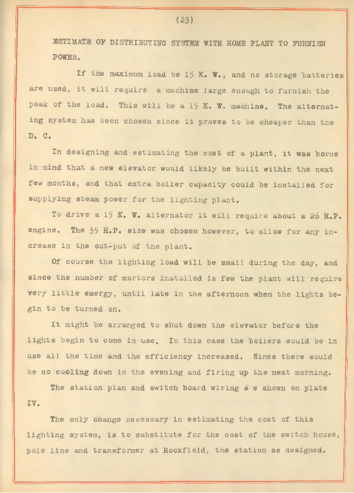
ESTIMATE OF DISTRIBUTING SYSTEM WITH HOME PLANT TO FURNISHPOWER.
I f the maximum load be 15 K. W., and no storage batteries are used, it w ill require a machine large enough to furnish the peak of the load. This w ill be a 1$ K. W. machine. The alternating system has been chosen since it proves to be cheaper than the D. C.
In designing and estimating the cost of a plant, it was borne in mind that a new elevator would likely be built within the next few months, and that extra boiler capacity could be installed for supplying steam power for the lighting plant.
To drive a 15 K. W. alternator it w ill require about a H.P. engine. The 35 H.P. size was chosen however, to allow for any increase in the out-put of the plant.
Of course the lighting load w ill be small during the day, and since the number of mortors installed is few the plant w ill require very l i t t l e energy, until late in the afternoon when the lights begin to be turned on.
It might be arranged to shut down the elevator before the lights begin to come in use. In this case the boilers would be in use a ll the time and the e ffic ien cy increased. Since there would be no coaling down in the evening and fir in g up the next morning.
The station plan and switch board wiring a e shown on plate IV.
The only change necessary in estimating the cost of this lighting system, is to substitute for the cost of the switch house, pole line and transformer at Rockfield, the station as designed.

(24)
COST
15 K. W. Alternator - - - - - - - - $300
1.5 K. W. exciter - - - - - - - - - 60
35 H. P. engine - - - - - - - - - - 714
Engine setting - - - - - - - - - - - 86
Switch hoard - - - - - - - - - - - - 250
Building - - - - - - - - - - - - - - 280
Labor for constructing - - - - - - - 210TOTAL COST---------- -------------------$1900
Total cost for transmission system = $6470.Cost of pole line, Switch house and transformer at Rockfield
= $2930.6470 - 2930 = $35403540 + 1900 = $5440 total cost of system using home
plant to furnish power.Assuming the same amount of energy to he sold, the income per
month for station output is $288.Two attendants at $75 per month = $150Coal required to supply the boilers with steam for generator
*
load is estimated at 1/2 ton per day. Assuming $200 per ton the cost of coal is $1.00 per day.
]?o.r one month cost = $30
$150 + $30 « $ l80
288 - 180 = $108 net proceeds per month.108 x 12 a $1296 per year.
= 23.8 V o interest and depreciation.
Allowing 8 ° /° f ° r depreciation the interest on the investment w ill be 15.8 °/o
( 25)
Of course no absolutly correct figuring can be furnished since the number and location of lights to be taken, is not known. At best we say this thesis gives an approximate result to what actually would be found.
It seems that the better proposition would be to construct a plant to furnish the power. One of the great advantages of such a supply of energy is that it is not dependant upon some outside party.

SWITCH - HOUSE.

PLATE.

PLATE m
G EpERHTiHG Station. Crockcr-Wh e e ler Th r e e Ph a s e R l t e r n r t o r . -J 5 K.W.
Wa t e r t o w n E n g in e J J H . f ? 3Z0 R.PM.
(VlWWWW
Exciter.
Po w e r P l a n t Fo r C h m d e n E l e c t r i c L i g h t i n g St a t io n
Scale i* fA. P e n n
pc. vmFu ses
Ground Detector-
D. C. /J/77.D.C. F/e/cT R h e o s ta t
. * Pilot Lamp
/?. c. Rm.
F.C. F/eJd Phostat.
R. c. Sw itchL D. C. S witch
i
in
/?, C. Voitape Trans.
Sw it c h - B oa r d C o n n e c t i o n s . G e n e r /j l E l e c t r i c M a k e .

(deale —/ igefalSt ,. „ „ -Pwi• \ V/̂ isthp’s ffidd 1P p ifto r i & B 'd dl P la e s £ fdd l W ood’s (R d d ( rP otrfetrs f f d d
m | dbdgdzFSOps R fdd \£)dgdeP60l2‘57?i?dfdd
l Hay d o d d ( dH zdepd p fd d
»\ fd d r fiiz d ff* d d{ M in# p d d( Omgigal To&q1 U n p la tted
CAMDEN MMMA1MA
' iRC LA M P .
T R E E T l NCR N D ESCENT
TRANSFORMER.SW ITCH H O U S E .
M R I NS F O R S T R E E T LIGHTING.
___ ___ __________ M R !N S F O R H O U S E L IG H T IN G .


![Camden journal (Camden, S.C.).(Camden, S.C.) 1852-08-27 [p ].j \ * t - "V* J',. r * I i CAMD U. 1; VOLUME3. CAMDEN,SOUTH-CAROLINA,AUGUST^1852. ' NUMBER69. THE CAMDEN JOURNAL. published](https://img.pdfslide.net/doc/110x75/5fa2071a08dcde766c594b2a/camden-journal-camden-sccamden-sc-1852-08-27-p-j-t-v.jpg)


![The Camden Chronicle (Camden, S.C.). 1902-05-16 [p ]](https://img.pdfslide.net/doc/110x75/629de903deda946b42048dc1/the-camden-chronicle-camden-sc-1902-05-16-p-.jpg)