Embed Size (px)
Citation preview

American Institute of Aeronautics and Astronautics
1
Design of an Experimental Platform for Acquisition of
Liquid Slosh Data aboard the International Space Station
Sunil Chintalapati1, Charles A. Holicker
2, Richard E. Schulman
3, Esteban Contreras
4, Hector M. Gutierrez
5, and
Daniel R. Kirk6
Florida Institute of Technology, Melbourne, FL, 32901
Liquid propellant slosh occurring during orbital maneuvers of a rocket’s upper-stage
may adversely affect vehicle performance. During orbital maneuvers the acceleration levels
of an upper-stage vary substantially and significant liquid sloshing events may occur which
can affect the intended trajectory of the vehicle as well as influence propellant and tank
thermal management. Mission planners require accurate and validated simulation tools to
understand and predict the effects of slosh on a mission and therefore there is a need to
better understand and model liquid slosh in micro-gravity.
This work aims to bridge the gap of missing data by designing a Slosh Platform capable
of acquiring long-duration low-gravity slosh data on the International Space Station. The
slosh data acquired will facilitate calibration and validation of CFD models. The proposed
experimental platform consists of a tank partially filled with water, inertial measurement
units to measure the dynamics of the system, as well as cameras to image the fluid
distribution in the tank. The Slosh Platform utilizes the existing ISS SPHERES apparatus,
which will be used to maneuver the tank through a variety of trajectories. To mimic the
motions of actual upper-stage rocket maneuvers, a scaling analysis based on relevant non-
dimensional parameters is performed and applied to the design and operation of the Slosh
platform onboard ISS. The proposed motion profiles to be conducted by the Slosh Platform
on ISS were verified using a CFD tool to assess the magnitude of fluid slosh and its impact
on the attitude change of the platform. The CFD tools predict that the liquid slosh within the
tank of the Slosh Platform will cause the trajectory of the apparatus to deviate in a
measurable way as compared with a rigid, non-sloshing system. Currently the experimental
design has passed NASA’s Critical Design Review and manufacture of the first test article is
in progress. The Slosh experiment is scheduled to fly to the ISS in July of 2013 with on-orbit
experiments to begin shortly thereafter.
I. Introduction and Background
loshing problems are of increasing concern in a rocket upper-stage and spacecraft applications. In space, the
influence of sloshing liquid propellants may hamper critical maneuvers such as docking of cargo vehicles or
pointing of observational satellites. Severe problems with sloshing liquid in spacecraft have been reported. As an
example of the potential slosh impact on rocket performance, a pre-launch review of the Computational Fluid
Dynamics (CFD) propellant slosh predictions within the second-stage of a Delta IV launch vehicle led to a launch
stand down until the issue could be resolved. The CFD predictions from the same tool varied significantly
depending on whether a 4 or 6- Degree of Freedom (DOF) model was used. A worst case scenario predicted that the
liquid hydrogen would not remain constrained in the aft end of the tank and could be ingested into the tank vent-
and-relief system resulting in a thrust imbalance and loss of vehicle control. The analysis team concluded that it was
imperative to “determine proper methodology for future Delta IV second-stage propellant slosh analysis”, (1). In
another example, the NEAR satellite went into safety mode because of an unexpected reaction that was possibly due
to propellant slosh after an orbital maneuver which caused a one year delay of the project, (2). Finally, recently in
1Graduate Research Assistant, Mechanical and Aerospace Engineering Department, AIAA Student Member.
2Graduate Research Assistant, Mechanical and Aerospace Engineering Department.
3Graduate Research Assistant, Mechanical and Aerospace Engineering Department, AIAA Student Member.
4Graduate Research Assistant, Mechanical and Aerospace Engineering Department.
5Associate Professor, Mechanical and Aerospace Engineering Department.
6Associate Professor, Mechanical and Aerospace Engineering Department, AIAA Associate Fellow.
S
48th AIAA/ASME/SAE/ASEE Joint Propulsion Conference & Exhibit30 July - 01 August 2012, Atlanta, Georgia
AIAA 2012-4297
Copyright © 2012 by the American Institute of Aeronautics and Astronautics, Inc. All rights reserved.
Dow
nloa
ded
by F
LO
RID
A I
NST
ITU
TE
OF
TE
CH
NO
LO
GY
on
July
27,
201
4 | h
ttp://
arc.
aiaa
.org
| D
OI:
10.
2514
/6.2
012-
4297

American Institute of Aeronautics and Astronautics
2
March of 2007, SpaceX Falcon 1 vehicle tumbled out of control(3). An oscillation appeared in the upper stage
control system approximately 90 seconds into the burn and instability grew in pitch and yaw axes initially and after
about 30 seconds also induced a noticeable roll torque .This roll torque eventually overcame 2nd stage‟s roll control
thrusters and centrifuged propellants, causing flame-out of the Kestrel engine. There is high confidence that LOX
slosh was the primary contributor to this instability. This conclusion has been verified by third party industry experts
that have reviewed the flight telemetry.(4).
Accurate prediction of coupled fluid slosh and launch vehicle or spacecraft dynamics (e.g., nutation, attitude
changes) requires CFD models calibrated with low-gravity, long duration slosh data. Recently completed
investigations of reduced gravity slosh behavior has demonstrated the limitations of utilizing parabolic flights on
specialized aircraft with respect to the specific objectives of the experiments. Although valuable data was collected,
the benefits of longer duration low-gravity environments were clearly established. Accurate knowledge of this
behavior is critical for a number of space based mission applications:
Launch vehicle upper stages are often spun to provide stabilization during engine firing. Spinning upper
stages have nutation modes that can couple with on-board fluid slosh. Improper models of such coupling
can cause premature exhaustion of nutation damping propellant.
During the coast to apogee in a Geosynchronous Transfer Orbit, the microgravity conditions can allow
fluid to migrate to warmer portions of the tank leading to higher pressure and faster venting. This, in turn,
can reduce the amount of propellant available for plane change and circularization maneuvers.
Plane change maneuvers require a reorientation of the spacecraft. This rotation can cause the fluid to
redistribute throughout the tank causing asymmetric venting, center of mass migration, and non-uniform
distribution to the engine.
On-orbit servicing is a means for re-fueling satellites, transferring cargo to manned assets, and assembling
large structures in space. Maneuvering servicing vehicles with large fluid tanks in close proximity to other
spacecraft requires accurate knowledge of the dynamics (including slosh) to ensure accurate relative motion
control.
These cases and others underscore the need to develop a detailed, physics-based understanding of propellant
slosh behavior over a range of conditions and environments relevant for liquid rocket applications. CFD codes are
used to predict this behavior. However, no long-duration microgravity data exists to calibrate these models.
Calibration using data collected in an operationally realistic environment is essential to increasing the fidelity and
predictive capability of CFD tools. Extensive ground experiments, drop tower testing and parabolic “zero-g” flights
were completed and CFD model were validated,(5)(6)(7), but the need for long-duration, low-gravity data still
persists. The International Space Station (ISS) offers a particularly appealing blend of highly representative
microgravity dynamics, long campaign duration, and experimental accessibility.
II. Slosh Experiment Overview
The ISS provides an operationally realistic microgravity environment for fluid slosh experiments that cannot be
emulated on Earth. The slosh experiment therefore leverages the ISS as a unique research setting that enables
investigations relevant to NASA and industry that cannot be conducted elsewhere. Slosh payload consists of
optically transparent fluid-filled tanks, a vision system, an Inertial Measurement Unit (IMU), and a data storage unit,
which are added to Synchronized Position Hold Engage Reorient Experimental Satellites (SPHERES) system.
SPHERES platform was developed initially at Massachusetts Institute of Technology (MIT), consists of small free-
flying satellites, each with CO2 cold gas thrusters and a thruster fuel tank. Slosh hardware will be used to conduct
sequences of repositioning maneuvers and document the resulting fluid slosh behavior through correlated video and
IMU data for off-board image processing. Acquired data from slosh experiment will then be used to calibrate CFD
fluid slosh models, improving the design of launch vehicle upper stages, spacecraft, and future planned flagship
technology demonstrations.
There are two configurations to Slosh Platforms and each configuration has the liquid tank in two distinct axes.
The advantages of Configuration A are the overall system mass is lower and hence the Bond number for the
configuration is higher, and system CG of Configuration A is more sensitive to fuel imbalance in SPHERES CO2
gas tanks. Configuration B has a higher system mass; a higher radius tank and more fill volume resulting in lower
acceleration. The Bond number is however higher due to the bigger radius. The overall liquid mass to system mass
is also better than Configuration A. The fuel imbalance in SPHERES CO2 gas tanks is significantly less as
compared with liquid mass impact on overall system CG. Both Configurations use the same structural components
and require no additional fixtures.
Dow
nloa
ded
by F
LO
RID
A I
NST
ITU
TE
OF
TE
CH
NO
LO
GY
on
July
27,
201
4 | h
ttp://
arc.
aiaa
.org
| D
OI:
10.
2514
/6.2
012-
4297

American Institute of Aeronautics and Astronautics
3
A proposed view of the Configuration A and Configuration B is shown inFigure 1a andFigure 1b.The payload
container is a visually transparent Lexan tank to allow recording of the fluid motion inside the tank during the
maneuvers. Also shown are manifested flight hardware SPHERES and Visual Estimation and Relative Tracking for
Inspection of Generic Objects (VERTIGO).
Figure 1 Schematic of ISS Slosh Experiment (Hood off), (a) Configuration A, (b) Configuration B
These figures (Figure 1a andFigure 1b) showsslosh payload without the enclosure (or hood) over the liquid tank.
Enclosure is used to control the lighting source and intensity during an experiment, which is critical for image
acquisition of liquid distribution within the tank. The next series of sub-sections presents an overview of slosh
payload.
A. Manifested Flight Hardware: SPHERES and VERTIGO
The SPHERES test bed provides a unique, free-floating and existing instrumented platform on ISS that can be
utilized in a manner that would solve many of the limitations of the current knowledge related to propellant slosh
dynamics on launch vehicle and spacecraft fuel tanks. SPHERES is a modular system, able to accommodate one or
several payloads hard-mounted through the expansion port or mounted using other fasteners to any of the sides of
the satellite, as long as they do not block a large number of ultrasound receivers or propulsion system nozzles.
Figure 2 A SPHERES microsatellite (left) and 3 SPHERES deployed on ISS (right)
The SPHERES hardware consists of multiple self-contained satellites, each with battery power, a cold gas
propulsion system, and onboard communications and navigation equipment (Figure 2). Using ultrasound transmitter
beacons mounted inside ISS, the satellites individually measure their respective positions and attitudes in relation to
one other and to the defined test volume. SPHERES provides a unique opportunity for researchers on the ground to
test software, algorithms, maneuvers, and procedures on ISS, receive testing data, then refine and uplink new test
protocols in a relatively short period of time, thus contributing to an accelerated iterative process unavailable in
other microgravity testing environments. Chief among these is the presence of an expansion port on each SPHERES
satellite, which allows hardware to be attached, and controlled using the existing SPHERES command and control
software. In addition, SPHERES was designed so that software is not a safety critical subsystem, so any
modifications that need to be performed in order to properly test attached hardware such as the fluid slosh payload
do not have to undergo an independent software review by NASA before they are approved for use on-board ISS.
VERTIGO is an expansion payload for SPHERES which functions as a test bed for space based inspection
experiments. It is comprised of a Pico –ITX P830 computer running Linux Ubuntu, 64GB SSD storage, a stereo
Dow
nloa
ded
by F
LO
RID
A I
NST
ITU
TE
OF
TE
CH
NO
LO
GY
on
July
27,
201
4 | h
ttp://
arc.
aiaa
.org
| D
OI:
10.
2514
/6.2
012-
4297

American Institute of Aeronautics and Astronautics
4
vision camera system, and other associated hardware such as power regulators, expansion ports, and a control panel
all powered via an EN-EL4A 11.4V battery. Due to the modular design of SPHERES and VERTIGO, it is relatively
easy to attach secondary payloads to use pieces of the existing hardware and slosh Avionics hardware is connected
through the Top board replacing the Optics board. This configuration is extremely beneficial to the slosh experiment
as it reduces the amount of new hardware needed to be transported, used and tested, as well as providing the
opportunity for future upgrades and missions.
B. Liquid Slosh Tank Design
The primary aspect of slosh payload is partially liquid filled tank. The criteria for selection of tank is based on
various factors. The main factors that influence the tank design selection are the critical dimensions, which are
determined by the application of non-dimensional parameters. The shape of the tank is derived from a upper-stage
propellant tank. The material type, thickness, working fluid, and fill volumes also play an important role in the
selection. Based on numerous analyses, a tank with radius of 0.075 m (2.95 inches) inner diameter (ID) and
0.00635m (¼ inch) tank thickness was selected. Tank material type is Lexan, based on the approval rating for
material acceptable for use on ISS. Water was chosen as the baseline fluid, and fill volume was determined by non-
dimensional numbers and deviations recorded in numerical studies.
C. Instrumentation and Data Acquisition
This section details the instrumentation and data acquisition to be used on slosh platform.
C.1. Slosh Avionics
Slosh Avionics is an external supplement to the existing SPHERES payload VERTIGO which brings necessary
hardware to monitor slosh events, including a 6-DOF sensor, a high speed Megapixel monochromatic camera and
other necessary components. Connection to the SPHERES test bed is done via the expansion port on the VERTIGO
main computer, replacing the existing camera Optics board with the slosh Avionics package in single contained unit
per SPHERES satellite.
The hardware was selected to satisfy the requirements for accurate slosh recognition such as: image resolution
and pixel depth for edge detection, minimum frames per second of video for test size and time delta comparison,
sensor resolution for accurate data collection, Ethernet and USB communication protocols and solid state drives for
real time storage of data, and finally computer configuration and operating software for system reliability and
expandability.
The video data has a maximum resolution of 2592 x 1944, representing a rectangular area which accommodates
the pill shaped vessel used for the experiment. The 12bit depth pixels means subtle differences in the
monochromatic images can be recorded, thus capturing small details such as droplet shading. At 14.7 frames per
second average on the cameras, and IMUs running at 300 MHz, enough data is recorded to make comparisons with
CFD models at small time steps in order to validate results. The 1.2 GHz processor saves data to the solid state drive
ensuring work in real time with no concerns about buffering or losing temporarily stored data. Finally, Ubuntu
Linux which is a free amply tested operating system is used due to its light weigh performance cost and ease of
customization/programming compared to other solutions.
The entire slosh test bed is comprised of two identical twin systems where SPHERES satellites communicate
and control VERTIGO payloads which interface with slosh Avionics. Cameras and IMU are controlled by their local
SPHERES computer, while the satellites work under a wireless masters-slave relationship to ensure synchronicity
between data. Information obtained is time stamped and stored internally until such time when it can be easily
downloaded to the ISS computers for transmission to Earth.
VERTIGO and Slosh Avionics produce an approximate of 75MB/s of information including five Megapixel
videos at 14 fps. The different sensors range from ±25.6mg to ±2g of acceleration and ±83o
to ±2000o of gyration,
where g denotes the constant for standard gravity. Operation is battery powered with a maximum runtime of
approximately 1 hour.
C.2. Camera System
Two Basler Ace acA2500 5Mega pixel cameras are used in slosh experiment (Figure 3a). Figure 3b and Figure
3c shows the lighting options being tested at Florida Tech.
Dow
nloa
ded
by F
LO
RID
A I
NST
ITU
TE
OF
TE
CH
NO
LO
GY
on
July
27,
201
4 | h
ttp://
arc.
aiaa
.org
| D
OI:
10.
2514
/6.2
012-
4297

American Institute of Aeronautics and Astronautics
5
Figure 3 Image acquisition system, (a) Camera, (b) Side panel lighting option, (c) Bottom panel lighting
option
Each camera has a replaceable lens with non-variable focal length (Figure 3). They are connected via Ethernet to
the VERTIGO computers and are powered by the battery via a 12V DC/DC converter. Cameras are attached to the
frame via a dovetail and have its power and data cables routed through the Slosh Avionics module for power and
signal conditioning. Cameras alignment is done on ground by adjusting the dovetail base frame. Since this is a solid
piece with no moving parts, replacement of cameras requires no realignment or adjusting from the operator.
C.3. Inertial Measurement Unit
Two CHR UM6 sensors are used per VERTIGO box to ensure reliability of data. They are connected via a
FTDI communications interface that allows use of the USB ports in VERTIGO. Power for the sensors is also
obtained from VERTIGO and is regulated by the FTDI chip. Additionally, data will also be recorded by sensors
inside each SPHERES. Table 1shows the range and resolution of these sensors.
Table 1 Range and resolution of sensors
SPHERES SLOSH AVIONICS CHR-UM6
IMU Range Resolution Range Resolution
Accelerometer 3DOF ±25.6 mg ±12.5 µg/LSB ± 2g ± 1 mg/LSB
Gyroscope 3DOF ±83 º/s ±0.0407 (º/s)/LSB ± 2000 º/s ± 0.0696 (º/s)/LSB
C.4. SPHERES-Slosh Platform Interface
There is no change in VERTIGO interface with SPHERES and regulations in place for the SPHERES-
VERTIGO interface are adequate. Slosh Avionics interfaces with VERTIGO via ERM8 and ERF8 as discussed in
previous subsections. The SPHERES units need to be rigidly attached to the slosh package in a known orientation.
This is accomplished by fitting the SPHERES unit into a negative half mold of the SPHERES outer shell. A draw
clamp grips the CO2 tank of the SPHERES holding it firmly in a known orientation. Consideration for thruster
obstruction was taken and cutouts in the negative mold give the thrusters clearance to fire without obstruction.
C.5. Command and Data Handling
Figure 4 shows the detailed schematic from top to bottom of the system and its operation during an experiment.
Operation of the system starts with SPHERES. The astronaut (crew member) will indicate the start of the
experiment along with its parameters using the provided controls on the physical body of SPHERE 1. At this point,
SPHERE1will indicate to SPHERE 2 the start of such experiment through a synchronized wireless signal. This
signal will mark the trigger for both VERTIGO Avionics simultaneously using a UART serial port connected from
the SPHERES to their respective PICO ITX P830 computers. At this instance, both sides will ideally behave
identically (max delay of 1 milli-second). The PICO ITX P830 computer will initiate software and hardware
including the cameras and sensors to match the experiment requirements. Communications between the computer
and camera is done through a Gigabit Ethernet port. Communications between the computer and the inertial
measurement sensor (IMU) is done through USB using a FTDI as an intermediary. The FTDI also provides the
additional benefit or regulating power for the sensor. Power for the camera is handled between the Slosh Avionics‟
PXD30W regulator and the VERTIGO combined board.
Dow
nloa
ded
by F
LO
RID
A I
NST
ITU
TE
OF
TE
CH
NO
LO
GY
on
July
27,
201
4 | h
ttp://
arc.
aiaa
.org
| D
OI:
10.
2514
/6.2
012-
4297

American Institute of Aeronautics and Astronautics
6
Figure 4 Top level system schematic of power and data handling
The software controlling the PICO ITX P80 computer is a custom automated program running on top Linux
Ubuntu 10.4. It handles all communications, storage and control of all other hardware. Data transfer speed and
hardware requirements have been experimentally checked.
D. Support Frame
The optimal configuration for the experiment is when the tank is balanced in terms of center of gravity (CG).
Key frame dimensions are designed to result in an overall system dry CG located at the center of the tank. This
ensures that all maneuvers are executed about the tank center and no rotational offsets are incurred. The cameras are
positioned to have a clear and unobstructed view of the tank and the fluid inside. These two cameras are in an
orthogonal configuration for image processing and data extraction purposes. Since the cameras are essential for
capturing the free surface shape of the fluid inside the tank, proper lighting and background are vital. Artificial
lighting from an LED strip provides adequate lighting for the cameras to capture liquid free surface. A hood
enclosure eliminates any effects of ISS lighting on experiment. The background or the view behind the tank consists
of a flat black surface lined with a contrasting grid. This not only gives a good image of free surface shape, but the
grid overlay on the background helps identify the fluid distribution numerically.
The frame arms are designed to secure SPHERES rigidly to main frame. Center hub assembly design can
accommodate liquid tank and an enclosure type system for slosh payload. The cameras are held at top corners of
center hub assembly.The strength-weight optimization of the frame meets factor of safety guidelines set by NASA
and ISS. Structural analysis was performed to give the frame proper rigidity under adverse loading while still being
lightweight. Array of stowage types for possible launch vehicles provided by JSC were analyzed for flight package
fitment and slosh payload modularized to fit two package sizes of stowage bags available in most launch vehicles,
including SpaceX.
III. Application of Non-dimensional Parameters and Hydrodynamic Regimes
The primary purpose of slosh experiment is to provide relevant experimental data to benchmark numerical code.
An understanding of the various hydrodynamic regimes, such as acceleration dominated, momentum dominated and
capillary dominated flow behavior is needed(8). A quick look at typical acceleration profile for a rocket upper-stage
maneuver categorically rules out a direct replication of the maneuvers with slosh payload onboard ISS. Guidance is
sought from the non-dimensional number from rocket upper-stage maneuvers and their relationship to various
hydrodynamic regimes. These non-dimensional number and hydrodynamic regimes are matched to slosh Payload
Dow
nloa
ded
by F
LO
RID
A I
NST
ITU
TE
OF
TE
CH
NO
LO
GY
on
July
27,
201
4 | h
ttp://
arc.
aiaa
.org
| D
OI:
10.
2514
/6.2
012-
4297

American Institute of Aeronautics and Astronautics
7
maneuver onboard ISS. Subsequent numerical calculations are performed to verify the nature of fluid slosh both in
rocket upper-stage propellant tank and slosh tank.
The approach for non-dimensional mapping is done via a comprehensive literature search of the rocket upper-stage
maneuvers. Essential variables are identified and a coding methodology is introduced for each maneuver. Major
results from the code are tabulated and plotted.
Before proceeding with this analysis the constraints for slosh payload onboard ISS are identified and they are:
Test Space: Usable test space inside ISS capsule is limited; an envelope of 2.5m x 2.5m x 2.5m is used as a
limiting condition for all experiments within ISS.
Thrust forces: A set of SPHERES can provide a maximum of 0.44 N thrust with simultaneous firing of four
thrusters.
Limited crew time: Each test session are limited to a 4 hour session, which takes into account the setup and
breakdown of SPHERES, VERTIGO and slosh Payload.
An initial properties search was performed on National Institute of Standard and Technology (NIST) chemistry
webbook for fluid properties of liquid hydrogen(9), liquid oxygen(10) and water(11) at appropriate temperature and
pressure ranges. This summary is shows in the first three columns of Table 2. Four parameters were identified for
comparison and determining an ideal working fluid. The four parameters are viscosity, surface tension, contact angle
and a ratio of density over surface tension. Relevant fluid were selected based on the four parameter discussed above
and two favorable fluids are listed in Table 2 in the two column in the extreme. The two fluids are 3M Novec
engineering fluid(12) and Silicone oil(13). Comparison with three of the four parameters yielded good agreement
with cryogenic propellant fluids and the only missing parameter for comparison was contact angle.Contact angle
was determined experimentally at Florida Tech (for water and Novec).
Table 2 Relevant properties of fluid in liquid phase
A. Non-dimensional Parameter Analysis for Slosh Tank and Working Fluid
Tank sizing needed to be performed before the design iterations for combining SPHERES and VERTIGO
platform with SloshPlatform. The shape of slosh tank is based on the typical schematic from rocket upper-stage but
with smooth interior walls. Guidance for tank sizing is pursued via non-dimensional parameter approach. The other
aspect of non-dimensional analysis for slosh tank was to provide an initial estimate of fill volume of liquid. Figure
5is developed for three different fill levels based on the system mass (derived from radius of tank with a fill volume
of water).
(a) Bond number vs. radius (b) Velocity vs. radius (c) Liquid to system mass vs. radius
Figure 5 Non-dimensional parameter analysis for slosh tank
Dow
nloa
ded
by F
LO
RID
A I
NST
ITU
TE
OF
TE
CH
NO
LO
GY
on
July
27,
201
4 | h
ttp://
arc.
aiaa
.org
| D
OI:
10.
2514
/6.2
012-
4297

American Institute of Aeronautics and Astronautics
8
Four SPHERES thruster provides a combined thrust of 0.44 N, acceleration is computed from Newton‟s second
law and Bond number is computed (Figure 5a). This figure shows the varying trend of bond number with increasing
tank radius. System velocity is computed using a momentum balance equation, where the velocity of liquid initially
at center of tank, which is zero and after the system traverses twice the radius in distance, the combined mass of
system and liquid is used to compute the velocity(Figure 5b).
A quick look at the non-dimensional number for the three different fluid selected earlier reveals Novec and
silicone fluid are more prone (Bond number) to slosh than water (Figure 6). Weber and Reynolds number is based of
characteristic velocity. When SPHERES thrusters are fired to induce a spinning motion in tank, angular velocity of
tank is converted to linear velocity. Novec fluid has a higher density than Silicone fluid and both fluids have
comparable surface tension and thus significantly high Weber numbers (Table 2). Silicone fluid has much lower
viscosity, resulting in high Reynolds number (at 0.45 m/s velocity, Silicone fluid has a Reynolds number of
2.8E+07).Figure 6shows varying weber and Reynolds number, which is based on the varying characteristic velocity.
(a) Weber number vs. velocity (b) Reynolds number vs. velocity
Figure 6 Non-dimensional parameter analysis for working fluid
B. Rocket Upper-stage Maneuvers
Non-dimensional numbers for three maneuvers evaluated for rocket upper-stages and compared to slosh
experiment. It was found that it is impossible to match all numbers simultaneously, but flow regimes and individual
non-dimensional numbers can be matched. A comprehensive literature search on rocket upper-stage was performed
initially to gather information about information of the maneuver, thrusters, acceleration ranges, velocity ranges etc.
and few of the references are listed in this document, (1)(14)(15)(16)(17)(18)(19)(20). A detailed summary for the
three different maneuvers is presented below.
B.1. Settling Thrust Maneuver
This maneuver is performed to relocate random liquid distribution to sump-end of propellant tank. Initial
velocity of liquid relative to tank‟s velocity is zero and initial liquid distribution is at random location at top portion
of tank. The tank needs to traverse a distance (approximated at 2r) for liquid to come in contact with tank bottom.
The moment of impact or contact ascertains the velocity of liquid, which deteriorates at later portions of coast
(relative velocity of liquid being considered, not actual velocity of rocket upper-stage). Variable acceleration
parameters provide variable Bond numbers for both upper-stage and slosh experiment. Impact velocity calculations
determine Weber and Reynolds numbers for both upper-stage and slosh experiment.
B.2. Attitude Change (Pitch to Reorient) Maneuver
Attitude Change or Pitch to Reorient maneuver performed for, alignment with a specified orbit, spacecraft or
space station, with a satellite. Attitude change maneuver typically involves 90 degree pitch/yaw plane traverse and
involves both translational and rotational components of accelerations and velocities. Typically rocket upper-stages
also spin at a specified rate during this maneuver. This maneuver is also similar to Collision and Contamination
Avoidance Maneuver (CCAM). This maneuver is tough to simulate via slosh experiment owing to complexity in
controls algorithm for SPHERES and thruster input.
Dow
nloa
ded
by F
LO
RID
A I
NST
ITU
TE
OF
TE
CH
NO
LO
GY
on
July
27,
201
4 | h
ttp://
arc.
aiaa
.org
| D
OI:
10.
2514
/6.2
012-
4297
American Institute of Aeronautics and Astronautics
9
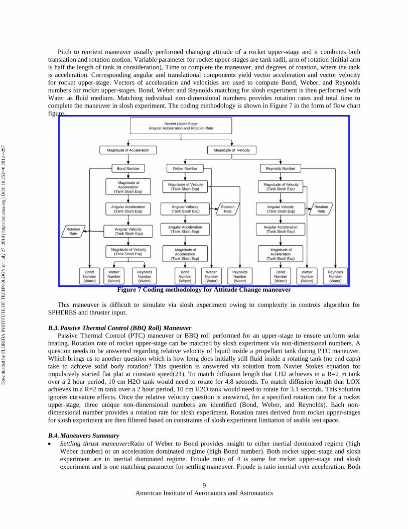
Pitch to reorient maneuver usually performed changing attitude of a rocket upper-stage and it combines both
translation and rotation motion. Variable parameter for rocket upper-stages are tank radii, arm of rotation (initial arm
is half the length of tank in consideration), Time to complete the maneuver, and degrees of rotation, where the tank
is acceleration. Corresponding angular and translational components yield vector acceleration and vector velocity
for rocket upper-stage. Vectors of acceleration and velocities are used to compute Bond, Weber, and Reynolds
numbers for rocket upper-stages. Bond, Weber and Reynolds matching for slosh experiment is then performed with
Water as fluid medium. Matching individual non-dimensional numbers provides rotation rates and total time to
complete the maneuver in slosh experiment. The coding methodology is shown in Figure 7 in the form of flow chart
figure.
Figure 7 Coding methodology for Attitude Change maneuver
This maneuver is difficult to simulate via slosh experiment owing to complexity in controls algorithm for
SPHERES and thruster input.
B.3. Passive Thermal Control (BBQ Roll) Maneuver
Passive Thermal Control (PTC) maneuver or BBQ roll performed for an upper-stage to ensure uniform solar
heating. Rotation rate of rocket upper-stage can be matched by slosh experiment via non-dimensional numbers. A
question needs to be answered regarding relative velocity of liquid inside a propellant tank during PTC maneuver.
Which brings us to another question which is how long does initially still fluid inside a rotating tank (no end caps)
take to achieve solid body rotation? This question is answered via solution from Navier Stokes equation for
impulsively started flat plat at constant speed(21). To match diffusion length that LH2 achieves in a R=2 m tank
over a 2 hour period, 10 cm H2O tank would need to rotate for 4.8 seconds. To match diffusion length that LOX
achieves in a R=2 m tank over a 2 hour period, 10 cm H2O tank would need to rotate for 3.1 seconds. This solution
ignores curvature effects. Once the relative velocity question is answered, for a specified rotation rate for a rocket
upper-stage, three unique non-dimensional numbers are identified (Bond, Weber, and Reynolds). Each non-
dimensional number provides a rotation rate for slosh experiment. Rotation rates derived from rocket upper-stages
for slosh experiment are then filtered based on constraints of slosh experiment limitation of usable test space.
B.4. Maneuvers Summary
Settling thrust maneuver:Ratio of Weber to Bond provides insight to either inertial dominated regime (high
Weber number) or an acceleration dominated regime (high Bond number). Both rocket upper-stage and slosh
experiment are in inertial dominated regime. Froude ratio of 4 is same for rocket upper-stage and slosh
experiment and is one matching parameter for settling maneuver. Froude is ratio inertial over acceleration. Both
Dow
nloa
ded
by F
LO
RID
A I
NST
ITU
TE
OF
TE
CH
NO
LO
GY
on
July
27,
201
4 | h
ttp://
arc.
aiaa
.org
| D
OI:
10.
2514
/6.2
012-
4297

American Institute of Aeronautics and Astronautics
10
rocket upper-stage and slosh experiment have a less fluid mass compared to enormous structural mass of rocket
upper-stage matched to slosh experiment by Froude (Figure 8a).
Attitude Change or Pitch to Reorient maneuver, rocket upper-stage matched to slosh experiment by matching
scaled rotation rate. Ratio of Weber to Bond provides insight to either inertial dominated regime (high Weber
number) or a gravitational dominated regime (high Bond number),. Since matching each individual non-
dimensional number for slosh experiment provides complementary non-dimensional numbers, data points for
slosh experiment tend to be more in number than rocket upper-stage data points. Rotation rate in slosh
experiment is clipped to a maximum of 10 deg/s (Figure 8b).
Figure 8 Weber vs. Bond number, (a) Settling Thrust, (b) Attitude Change
Passive Thermal Control, rocket upper-stage matched to slosh experiment by matching rotation rates for each
individual upper-stage non-dimensional number. Table 3 shows expected rotation rate (in deg/s) for slosh
experiment to match non-dimensional numbers for typical rocket upper-stage.
Table 3 Sample results of Passive Thermal Control maneuver
Dow
nloa
ded
by F
LO
RID
A I
NST
ITU
TE
OF
TE
CH
NO
LO
GY
on
July
27,
201
4 | h
ttp://
arc.
aiaa
.org
| D
OI:
10.
2514
/6.2
012-
4297

American Institute of Aeronautics and Astronautics
11
Bond, Weber and Reynolds numbers from upper-stage are used to derive individual rotation rates for specified
fluid and slosh Experiment dimensions (tank radius) and each non-dimensional number provides a unique rotation
rate. The grayed out boxes are rotation rates not possible on slosh experiment aboard ISS (hence filtered). Guidance
from non-dimensional mapping provides input to experiments performed and priority
IV. Kinematics Analysis
A primary step in the analysis of Slosh Platform is to understand the effect of forces and moments on the
platform. A free body diagram is helpful in quantifying the applicable forces and moments on Slosh Platform. Each
SPHERES platform has 12 thruster, providing 0.11 N thrust per thruster. From a SPHERES CG perspective, each
unique axis (-x, -y, -z, +x, +y, +z) of SPHERES has two thruster aligned in its direction. Thus Slosh Platform has
two SPHERES, which consists of a total of 24 thrusters (the first thruster id is 0 and the last thruster id is 23) and a
maximum thrust of 0.44 N is provided by 2 thrusters on each SPHERES for any unique axis direction. The
summation of net forces in any unique direction is equated to the product of mass and acceleration of the system.
For example to get a pure translation motion for SP in +y direction, thruster 4, thruster 5, thruster 22, and thruster 23
needs to be fired. Assuming the mass of the system to be 21 kg, an acceleration of 0.02095m/s2 is expected. Based
on constant acceleration assumption, the maximum velocity attained by Slosh Platform in a pure translation motion
is 0.354m/s (1.16 ft/s or 0.79mph). This calculation assumes at initial time the velocity is zero and the distance that
Slosh Platform can traverse is 3m (maximum limiting condition for ISS test space). When the CG of the system is
not overlapping the geometric center (GC) of the system, a net moment is applied at CG. For example, the
summation of moment in -x direction generated by a four thrusters firing in +y direction is 0.0016 N.m. For this
calculation, the distance of the thruster from the GC is 0.1 m (approximate in z-direction) and distance of CG from
GC is 3.6e-03 m (approximate in z-direction). After identifying the impact of forces and torque on Slosh Platform, a
review of CG shift and associated inertia matrix change due to fuel imbalance and liquid distribution is examined.
The motivation for this section is to quantify the deviations in trajectory to any specified motion profile. The
need to quantify the deviation is due to two reasons: 1) fuel imbalance in SPHERES and 2) Liquid mass (patched a
frozen mass). These reasons impact the CG of the overall system. A schematic showing the detailed CG of each
individual components in shown in Figure 9a.
Figure 9 CG envelope and associated inertia matrix change
The design intent for slosh platform is to have the CG of the dry system overlap the geometric center of slosh
tank. Dry system is defined as when the slosh platform contains no liquid in the tank and the fuel levels in CO2 cold
gas thruster for SPHERES are each half full. Thus having a CG overlap with geometric center of the tank and inline
with both SPHERES centroid ensures any thruster firing in longitudinal direction (y-axis) would result in a pure
translation motion (Figure 9a). This ideal situation is however not true when liquid is introduced in slosh tank. The
changing CG location and inertia matrix would not result in a pure translation motion, and could have motion in
other two axes. This situation; however, is complicated further due to the fact when SPHERES are attached to slosh
platform the fuel levels in both CO2 tank are not verified precisely. Moreover, the fuel levels in both SPHERES
during testing on ISS are likely to be unequal. The unknown fuel level variable results in a CG shift of the dry
Dow
nloa
ded
by F
LO
RID
A I
NST
ITU
TE
OF
TE
CH
NO
LO
GY
on
July
27,
201
4 | h
ttp://
arc.
aiaa
.org
| D
OI:
10.
2514
/6.2
012-
4297
American Institute of Aeronautics and Astronautics
12
system even before the liquid is introduced in slosh tank. Thus a thruster fire for a pure translation motion would not
result in a pure translation of empty slosh platform (no liquid in slosh tank). Note, whenever there is a changes is CG
of the system, there is an associated change in inertia of the system.
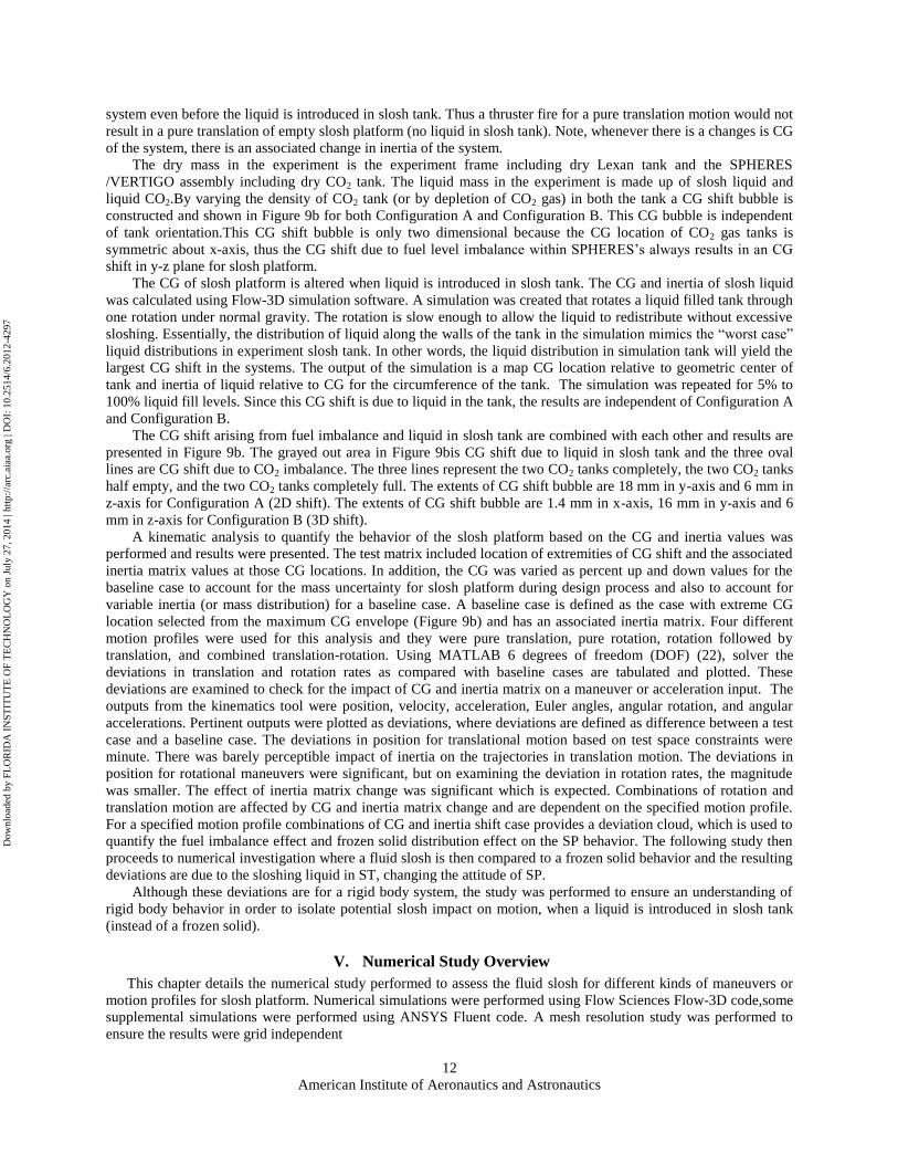
The dry mass in the experiment is the experiment frame including dry Lexan tank and the SPHERES
/VERTIGO assembly including dry CO2 tank. The liquid mass in the experiment is made up of slosh liquid and
liquid CO2.By varying the density of CO2 tank (or by depletion of CO2 gas) in both the tank a CG shift bubble is
constructed and shown in Figure 9b for both Configuration A and Configuration B. This CG bubble is independent
of tank orientation.This CG shift bubble is only two dimensional because the CG location of CO2 gas tanks is
symmetric about x-axis, thus the CG shift due to fuel level imbalance within SPHERES‟s always results in an CG
shift in y-z plane for slosh platform.
The CG of slosh platform is altered when liquid is introduced in slosh tank. The CG and inertia of slosh liquid
was calculated using Flow-3D simulation software. A simulation was created that rotates a liquid filled tank through
one rotation under normal gravity. The rotation is slow enough to allow the liquid to redistribute without excessive
sloshing. Essentially, the distribution of liquid along the walls of the tank in the simulation mimics the “worst case”
liquid distributions in experiment slosh tank. In other words, the liquid distribution in simulation tank will yield the
largest CG shift in the systems. The output of the simulation is a map CG location relative to geometric center of
tank and inertia of liquid relative to CG for the circumference of the tank. The simulation was repeated for 5% to
100% liquid fill levels. Since this CG shift is due to liquid in the tank, the results are independent of Configuration A
and Configuration B.
The CG shift arising from fuel imbalance and liquid in slosh tank are combined with each other and results are
presented in Figure 9b. The grayed out area in Figure 9bis CG shift due to liquid in slosh tank and the three oval
lines are CG shift due to CO2 imbalance. The three lines represent the two CO2 tanks completely, the two CO2 tanks
half empty, and the two CO2 tanks completely full. The extents of CG shift bubble are 18 mm in y-axis and 6 mm in
z-axis for Configuration A (2D shift). The extents of CG shift bubble are 1.4 mm in x-axis, 16 mm in y-axis and 6
mm in z-axis for Configuration B (3D shift).
A kinematic analysis to quantify the behavior of the slosh platform based on the CG and inertia values was
performed and results were presented. The test matrix included location of extremities of CG shift and the associated
inertia matrix values at those CG locations. In addition, the CG was varied as percent up and down values for the
baseline case to account for the mass uncertainty for slosh platform during design process and also to account for
variable inertia (or mass distribution) for a baseline case. A baseline case is defined as the case with extreme CG
location selected from the maximum CG envelope (Figure 9b) and has an associated inertia matrix. Four different
motion profiles were used for this analysis and they were pure translation, pure rotation, rotation followed by
translation, and combined translation-rotation. Using MATLAB 6 degrees of freedom (DOF) (22), solver the
deviations in translation and rotation rates as compared with baseline cases are tabulated and plotted. These
deviations are examined to check for the impact of CG and inertia matrix on a maneuver or acceleration input. The
outputs from the kinematics tool were position, velocity, acceleration, Euler angles, angular rotation, and angular
accelerations. Pertinent outputs were plotted as deviations, where deviations are defined as difference between a test
case and a baseline case. The deviations in position for translational motion based on test space constraints were
minute. There was barely perceptible impact of inertia on the trajectories in translation motion. The deviations in
position for rotational maneuvers were significant, but on examining the deviation in rotation rates, the magnitude
was smaller. The effect of inertia matrix change was significant which is expected. Combinations of rotation and
translation motion are affected by CG and inertia matrix change and are dependent on the specified motion profile.
For a specified motion profile combinations of CG and inertia shift case provides a deviation cloud, which is used to
quantify the fuel imbalance effect and frozen solid distribution effect on the SP behavior. The following study then
proceeds to numerical investigation where a fluid slosh is then compared to a frozen solid behavior and the resulting
deviations are due to the sloshing liquid in ST, changing the attitude of SP.
Although these deviations are for a rigid body system, the study was performed to ensure an understanding of
rigid body behavior in order to isolate potential slosh impact on motion, when a liquid is introduced in slosh tank
(instead of a frozen solid).
V. Numerical Study Overview
This chapter details the numerical study performed to assess the fluid slosh for different kinds of maneuvers or
motion profiles for slosh platform. Numerical simulations were performed using Flow Sciences Flow-3D code,some
supplemental simulations were performed using ANSYS Fluent code. A mesh resolution study was performed to
ensure the results were grid independent
Dow
nloa
ded
by F
LO
RID
A I
NST
ITU
TE
OF
TE
CH
NO
LO
GY
on
July
27,
201
4 | h
ttp://
arc.
aiaa
.org
| D
OI:
10.
2514
/6.2
012-
4297
American Institute of Aeronautics and Astronautics
13
A. Target Initial Condition
Liquid distribution in the slosh tank on the platform is not known a priori before the start of experimentation.
Furthermore, the crew (or astronauts) handling the slosh platform before experimentation would constantly change
the fluid distribution within the slosh tank. Although free surface shape could be numerically determined, knowing
actual fluid distribution in slosh tank before experiment is challenging. Astronauts would move slosh platform
before an experiment which would disturb any liquid settling and reorient liquid inside tank. Simple maneuvers are
performed to achieve „target‟ initial conditions (IC) before any experiment. Target IC are liquid distributions that
can be achieved in ISS which are similar to initial conditions on an upper-stage. Three options are determined in this
sub-study to achieve „target‟ IC
1. Liquid reorientation via abrupt acceleration and braking
2. Liquid reorientation via spinning tank on its minor axis
3. Liquid reorientation via spinning tank on its major axis
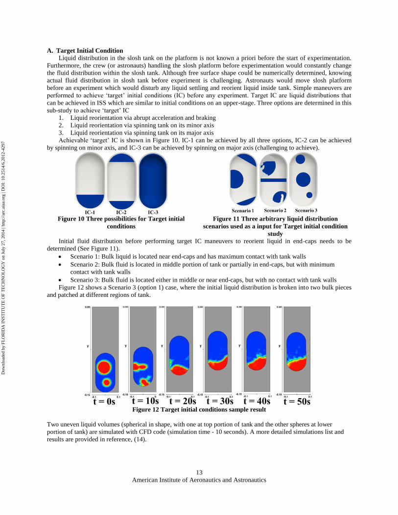
Achievable „target‟ IC is shown in Figure 10. IC-1 can be achieved by all three options, IC-2 can be achieved
by spinning on minor axis, and IC-3 can be achieved by spinning on major axis (challenging to achieve).
Figure 10 Three possibilities for Target initial
conditions
Figure 11 Three arbitrary liquid distribution
scenarios used as a input for Target initial condition
study Initial fluid distribution before performing target IC maneuvers to reorient liquid in end-caps needs to be
determined (See Figure 11).
Scenario 1: Bulk liquid is located near end-caps and has maximum contact with tank walls
Scenario 2: Bulk fluid is located in middle portion of tank or partially in end-caps, but with minimum
contact with tank walls
Scenario 3: Bulk fluid is located either in middle or near end-caps, but with no contact with tank walls
Figure 12 shows a Scenario 3 (option 1) case, where the initial liquid distribution is broken into two bulk pieces
and patched at different regions of tank.
Figure 12 Target initial conditions sample result
Two uneven liquid volumes (spherical in shape, with one at top portion of tank and the other spheres at lower
portion of tank) are simulated with CFD code (simulation time - 10 seconds). A more detailed simulations list and
results are provided in reference, (14).
Dow
nloa
ded
by F
LO
RID
A I
NST
ITU
TE
OF
TE
CH
NO
LO
GY
on
July
27,
201
4 | h
ttp://
arc.
aiaa
.org
| D
OI:
10.
2514
/6.2
012-
4297

American Institute of Aeronautics and Astronautics
14
B. Maneuvers
The purpose of this section is to numerically evaluate a motion profile and optimize the profile for ISS test
space consideration. The purpose of this section is also to numerically quantify the deviations caused by sloshing
liquid in any specified motion profile. The guidance for motion profiles comes from the rocket upper-stage
maneuvers, and since a direct replication of these maneuvers is not possible in ISS experimentation, guidance is
sought from non-dimensional mapping results. A vast number of simulations were performed to find the right
balance for motion profiles. The factors to consider while simulating a motion profile are
1. Duration of motion profile: An optimal balance is needed in order to ensure adequate amount of time is
provided in motion profile to simulate slosh and capture it.
2. Fuel consumption: Thrust is provided by SPHERES platform, which is powered by CO2 cold gas thruster.
A full tank contains 0.172kg of CO2, and since SPHERES provides a 0.11 N for each thruster, mass flow
rate of CO2 gas is computed by thrust equation and using choked flow equation. Thus mass flow rate of
CO2 is 4.05e-04 kg/s and maximum runtime for one full tank firing one thruster is approximately 425
seconds.
3. Usable test space: A constraint of 2m x 2m x 2m is enforced in all simulated motion profile. ISS safety
requirement does not allow for a free floating experiment to hit the walls of ISS or a crew member assisting
the experiment.
Figure 13 shows the results of Passive Thermal Control (BBQ Roll) maneuver. The sample input motion profile
for this maneuver consists of; At time equals zero, a positive torque applied in +y direction for a duration of 10
seconds, followed by a positive torque in +z direction for additional 10 seconds. The slosh platform is allowed to
coast for another 20 seconds and changing liquid distribution is monitored. Figure 13b, shows results of position in
inertial frame of reference. The plots show three different plot line, an empty slosh tank, slosh tank with solid at
20% fill volume (frozen liquid), and slosh tank with liquid at 20% fill volume. Figure 13b shows CG position in x, y
and z direction. Figure 13b shows series of time-stamped numerical images of liquid distribution in slosh tank. The
initial condition in this sample simulation in liquid in end-cap in the tank (this initial condition is same for both solid
and liquid cases). Each image is at transient time of 1 second.
Figure 13 Results (a) plot showing results deviation, (b) numerical images of liquid distribution
The comprehensive details of numerical simulation, list of cases, deviation, and pertinent non-dimensional numbers
are regimes are provided in reference, (14).
C. Working Fluid
A sub-set of study was performed to check for liquid distribution behavior and verify deviations with their
respective solid counterpart. Figure 14 shows an example of Settling Thrust maneuver for both water (blue color and
on left) and Novec (green color and on right) with all same input conditions. Novec fluid behavior is quite different
from water as can be seen in this example, but the deviation with solid Novec was less compared to water deviations
with its solid counterpart. This sub-set of study was performed for a variety of fill volumes and all three maneuvers.
Dow
nloa
ded
by F
LO
RID
A I
NST
ITU
TE
OF
TE
CH
NO
LO
GY
on
July
27,
201
4 | h
ttp://
arc.
aiaa
.org
| D
OI:
10.
2514
/6.2
012-
4297

American Institute of Aeronautics and Astronautics
15
Figure 14 Liquid distribution of water (on left) and Novec (on right) for a Settling Thrust
D. Experiment List
Experiment list (Table 4) and priority is based on some constraints
Time allotted for experiments: Two 240 minutes (4 hours) segments allotted to sloshexperiment. 120
minutes is reserved for SPHERES assembly/disassembly (pre-determined), 90 minutes will be reserved for
sloshexperiment/VERTIGO/Slosh Avionics (assumption), and 30 minutes of experimental time.
Additional time for data transfer to ISS computers, and subsequent download to ground
CO2 usage: Full tank of CO2 would provide approximately 7 minutes of continuous thruster firing for each
SPHERES (1 thruster)
Power usage: Full battery pack would provide approximately 80 minutes (1.2 hours)
Hard drive capacity: At a maximum write speed it would take 12 minutes to fill up a 64 GB hard drive
Table 4 Comprehensive experiment list for one test session
Three maneuvers will be simulated in ISS based on non-dimensional mapping studies to simulate typical rocket
upper-stage maneuvers
Maneuver 1: Settling Thrust
Maneuver 2: Passive Thermal Control (BBQ roll)
Maneuver 3: Pitch to Reorient Attitude Control
Dow
nloa
ded
by F
LO
RID
A I
NST
ITU
TE
OF
TE
CH
NO
LO
GY
on
July
27,
201
4 | h
ttp://
arc.
aiaa
.org
| D
OI:
10.
2514
/6.2
012-
4297

American Institute of Aeronautics and Astronautics
16
Maneuvers repeated three times (likely with different initial liquid distributions, time permitting). CO2 (95%), Power
(14%) and data collection (76% hard drive space) for allotted test sessions (645sec) are sufficient. Liquid tests can
each be repeated 3 times prior to CO2 exhaustion.
VI. Conclusion
In conclusion, an experiment platform design for acquisition of liquid slosh data aboard ISS is in place. Various
analytical and numerical simulations have been performed on slosh platform and brief summary of results are
presented in this paper. A relationship between rocket upper-stage maneuvers and Slosh Platform motion profiles on
ISS was decoupled via the application of non-dimensional numbers. The non-dimensional parameters also provided
insight to design of slosh tank and working fluid. A kinematics study was performed to assess the impact of CG shift
and associated inertia change on the Slosh Platform and deviations in trajectory were analyzed using a dynamics
tools ( which implements Matlab 6DOF Simulink block). Numerous numerical studies were performed to assess the
magnitude of liquid slosh on the experimental platform attitude change. A precursor to the motion profile numerical
study was target initial condition study performed to force any random distribution to a known and manageable
(easier to patch as input for CFD simulations) liquid distribution before performing any actual motion profile
experiments. The unabridged version of analysis and results are presented in a reference, (14). Supplemental studies
involve investigation of location of inertial measurement Unit (IMU), contact angle measurements, and consumables
usage.Currently the experimental platform design has passed NASA‟s Critical Design Review and manufacture of
the first test article is in progress. The slosh experiment is scheduled to be launched in July 2013.
Acknowledgments
The authors wish to express gratitude to Dr. Paul Schallhorn, Jacob Roth (NASA KSC, Launch Services
Program) and Brandon Marsell froma.i solutions for technical input and funding this project. The authors also wish
to thank Dr. Alvar Saenz-Otero and Dr. David Miller from MIT Space Systems Lab for technical advice regarding
SPHERES and VERTIGO.
References
1. Berglund, M D, et al. The Boeing Delta IV launch vehicle—Pulse-settling approach for second-stage hydrogen propellant
management. s.l. : Acta Astronautica. pp. 416-424.
2. Strikwerda, T E and et al. NEAR Shoemaker: Major anomaly survival, delayed rendezvous and mission success. Breckenridge,
CO : Guidance and control 2001, 2001. pp. 597-614.
3. Space Exploration Technologies Corporation - Update Archive. SpaceX. [Online] March 2007.
http://www.spacex.com/updates_archive.php?page=0107-0707.
4. SPACEX, Demo Flight 2 -Flight Review Update . s.l. : SPACEX, 2007. http://www.spacex.com/F1-DemoFlight2-Flight-
Review.pdf.
5. Vergalla, M, et al. Experimental and Numerical Framework for Characterization of Slosh Dynamics. s.l. : International
Review of Aerospace Engineering, Praise Worthy Prize S.r.l, 2009.
6. Chintalapati, S and et al. Enhanced Numerical Modeling in Simulation of a Generic Propellant Tank Slosh Baffle. Nashville :
American Institute of Aeronautics and Astronautics, 2010. AIAA 2010-6976.
7. Faure, J and et al. Experimental Platform for the Study of Liquid Slosh Dynamics Using Sounding Rockets. s.l. : International
Review of Aerospace Engineering, Praise Worthy Prize S.r.l., 2010. pp. 59-66.
8. Cengal, Yunus A and Cimbala, John M. Fluid Mechanics. s.l. : McGraw-Hill Science/Engineering/Math, December 20, 2004.
ISBN-13: 978-0072472363.
9. Isobaric Properties for Hydrogen . National Institute of Standards and Technology Chemistry Webbook. [Online]
http://webbook.nist.gov/cgi/fluid.cgi?Action=Load&ID=C1333740&Type=IsoBar&Digits=5&P=1&THigh=20&TLow=18&TIn
c=1&RefState=DEF&TUnit=K&PUnit=atm&DUnit=kg%2Fm3&HUnit=kJ%2Fkg&WUnit=m%2Fs&VisUnit=Pa*s&STUnit=N
%2Fm.
10. Isobaric Properties for Oxygen. National Institute of Standards and Technology Chemistry Webbook. [Online]
http://webbook.nist.gov/cgi/fluid.cgi?Action=Load&ID=C7782447&Type=IsoBar&Digits=5&P=1&THigh=91&TLow=89&TIn
c=1&RefState=DEF&TUnit=K&PUnit=atm&DUnit=kg%2Fm3&HUnit=kJ%2Fkg&WUnit=m%2Fs&VisUnit=Pa*s&STUnit=N
%2Fm.
11. Isobaric Properties for Water . National Institute of Standards and Technology Chemistry Webbook. [Online]
http://webbook.nist.gov/cgi/fluid.cgi?Action=Load&ID=C7732185&Type=IsoBar&Digits=5&P=1&THigh=298&TLow=298&T
Inc=0&RefState=DEF&TUnit=K&PUnit=atm&DUnit=kg%2Fm3&HUnit=kJ%2Fkg&WUnit=m%2Fs&VisUnit=Pa*s&STUnit
=N%2Fm.
12. 3M MATERIAL SAFETY DATA SHEET HFE-7100 3M (TM) Novec (TM) Engineered Fluid. s.l. : 3M Company, 2004. 07-
6378-9.
13. Material Safety Data Sheet, PSF-1cSt Pure Silicone Fluid, Octamethyltrisiloxane. 2012.
Dow
nloa
ded
by F
LO
RID
A I
NST
ITU
TE
OF
TE
CH
NO
LO
GY
on
July
27,
201
4 | h
ttp://
arc.
aiaa
.org
| D
OI:
10.
2514
/6.2
012-
4297

American Institute of Aeronautics and Astronautics
17
14. Chintalapati, S. Design of an Experimental Platform for Acquisition of Liquid Slosh Data aboard the International Space
Station. Melbourne, FL : Florida Institute of Technology, July 2012. Masters Thesis.
15. Delta DemoSat & Nanosat-2,Delta IV Heavy Demonstration Flight Media Kit. s.l. : Boeing, 2005.
16. Delta IV Payload Planners Guide. Huntington Beach, CA 92647-2099 : Boeing, 1999. MDC 99H0065.
17. GOES-N_Databook_RevC: Spacecraft Mission Profile. s.l. : NASA, 2009.
18. Juno Mission Profile&Timeline. spaceflight101. [Online] http://www.spaceflight101.com/juno-mission-profile-and-
timeline.html.
19. ULA_GOES-P_Mission_Book. s.l. : United Launch Alliance, 2010.
20. Ibrahim, Raouf A. Liquid Sloshing Dynamics. s.l. : Cambridge University Press, 2005. ISBN-13 978-0-521-83885-6.
21. White, Frank. Viscous Fluid Flow. s.l. : McGraw-Hill Science/Engineering/Math, January 5, 2005. ISBN-13: 978-
0072402315.
22. 6DoF (Euler Angles) . mathworks. [Online] http://www.mathworks.com/help/toolbox/aeroblks/6dofeulerangles.html.
Dow
nloa
ded
by F
LO
RID
A I
NST
ITU
TE
OF
TE
CH
NO
LO
GY
on
July
27,
201
4 | h
ttp://
arc.
aiaa
.org
| D
OI:
10.
2514
/6.2
012-
4297


![Interleukin-8 Is Produced in Neoplastic and Infectious ...cancerres.aacrjournals.org/content/canres/52/16/4297.full.pdf[CANCER RESEARCH 52, 4297-4305, August 15, 1992] Interleukin-8](https://img.pdfslide.net/doc/110x75/5cd5965e88c9937d508c0d32/interleukin-8-is-produced-in-neoplastic-and-infectious-cancer-research-52-4297-4305.jpg)