Embed Size (px)
Citation preview
275 | P a g e
DESIGN OF AN INNOVATIVE RETROFITTED
TRICYCLE FOR A DISABLED PERSON
Ajit A. Mohekar1, Savita V. Kendre
2, Tanmay N. Shah
3,
Prof. P. D. Sonawane4, Prof. Dr. S. T. Chavan
5
1,2,3 Undergraduate Student,
4Assistant Professor,
5 Professor, Department of Mechanical Engineering,
Maharashtra Institute of Technology, Pune, Maharashtra, (India)
ABSTRACT
Mobility of physically disabled persons is a concerning social issue nowadays. Various hand driven tricycles,
wheelchairs, retrofitted vehicles etc. are commonly available for disabled people as a mode of transportation.
Existing means of transportation for disabled people require a disabled person to dismount from the
wheelchair. A retrofitted tricycle is designed to overcome this problem by allowing the disabled person to wheel
up or down his wheelchair onto or down the tricycle. This is achieved using a specially designed platform that
allows the wheelchair to be wheeled up or down. This paper discusses an attempt to design and fabricate a
retrofitted tricycle for disabled people. This tricycle is specifically designed to suit wheelchair occupants.
Keywords: Disability, Disabled Person, Fabrication, Motorized Tricycle, Retrofitted Vehicle, Safety
Tests
I. INTRODUCTION
Transportation is one of the important sources for increasing mobility of human. In transportation, vehicles play
a very crucial role. Normal human being uses these vehicles very easily but for a disabled person it is very
inconvenient. Nowadays various hand driven tricycles are available for them but these are designed primarily
for the basic functional use for moving on road without considering many important aspects of safety,
ergonomic aspects and aesthetics[1]. Various methods have been researched and used to increase mobility of
disabled people. Some research are focused on improving the mobility of the wheelchair [1]. Motorized vehicles
such as buses, vans, cars and motorcycles are usually customized for this purpose. Customized vehicles such as
tricycles have been used by a disabled as a mean of transportation. However, existing tricycles require the
disabled to dismount from the wheelchair and get on to the tricycle. These are some of the problems that the
researchers are trying to solve with the new tricycle design.
This article is on the research of design and fabrication of a modified tricycle for disabled persons. The tricycle
is designed to accommo date a disabled person along with the wheelchair with ease and convenience. This is
achieved by allowing the disabled person to wheel up or down his wheelchair on the tricycle by using a
specially designed platform and ramp arrangement that allows the wheelchair to be wheeled up or down. It is
hoped that this new design will ease and improve mobility. The final engineering drawing as well as stress
analysis of essential components using commercially available 3D modelling software is done. The finalization
276 | P a g e
of the design of the tricycle is done by performing safety tests given by ARAI scheme [2]. An attempt has been
made to provide unique, cost-effective, purpose serving motorized retrofitted tricycle for disabled persons.
II. PROBLEM DEFINITIONS
To develop a unique, cost-effective, purpose serving motorized retrofitted tricycle for disabled person.
To design and fabricate a motorized retrofitted tricycle for disabled person for allowing the disabled person
to wheel up or down his wheelchair on to or down the tricycle.
III. LITERATURE REVIEW
Tatyaso Garande, et al. [1] discussed various modes of transport available and suitable for physically
handicapped persons for long and short distance travel. The modes are classified as per the maneuverity, ease,
automation and comfort. Various machines used for travelling of disabled persons include wheelchair, automatic
wheelchair, Smart wheelchair, retrofitted vehicles, tricycles, modified cars. Systematic comparison of all these
vehicles is carried out in this paper. Also considering advantages and drawbacks of each type, suggestions are
made for use of proper vehicles as per the handicapped person’s requirement. It shows that vehicles like
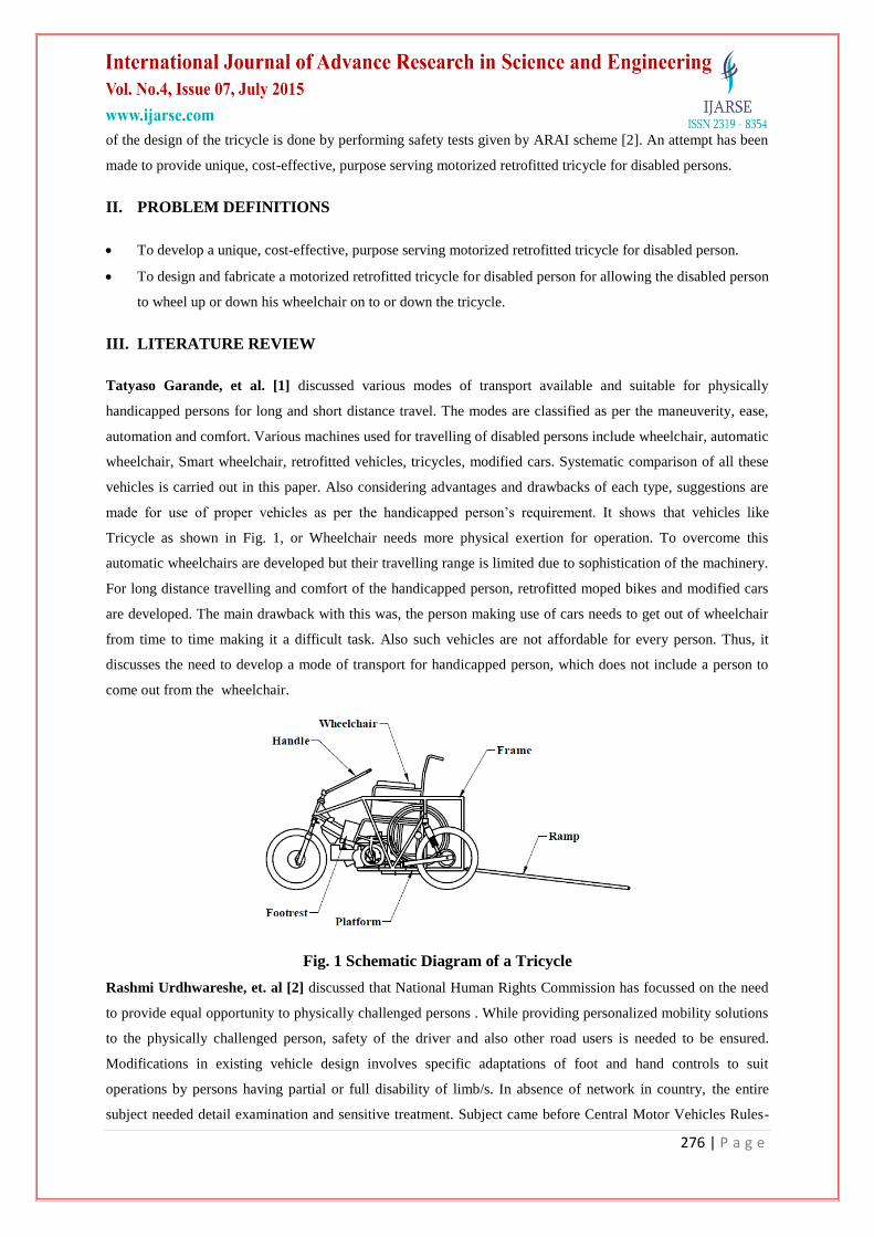
Tricycle as shown in Fig. 1, or Wheelchair needs more physical exertion for operation. To overcome this
automatic wheelchairs are developed but their travelling range is limited due to sophistication of the machinery.
For long distance travelling and comfort of the handicapped person, retrofitted moped bikes and modified cars
are developed. The main drawback with this was, the person making use of cars needs to get out of wheelchair
from time to time making it a difficult task. Also such vehicles are not affordable for every person. Thus, it
discusses the need to develop a mode of transport for handicapped person, which does not include a person to
come out from the wheelchair.
Fig. 1 Schematic Diagram of a Tricycle
Rashmi Urdhwareshe, et. al [2] discussed that National Human Rights Commission has focussed on the need
to provide equal opportunity to physically challenged persons . While providing personalized mobility solutions
to the physically challenged person, safety of the driver and also other road users is needed to be ensured.
Modifications in existing vehicle design involves specific adaptations of foot and hand controls to suit
operations by persons having partial or full disability of limb/s. In absence of network in country, the entire
subject needed detail examination and sensitive treatment. Subject came before Central Motor Vehicles Rules-
277 | P a g e
Technical Standing Committee (CMVR-TSC) and it was agreed that Automotive Research Association of India
(ARAI) will take the lead in resolving the matter and establishing approval procedure and notifying the
requirement under CMVR which restricted the individuals from altering their existing vehicles in general.
Po Er Hsu, et al. [3] explained the development of “Intelligent Robotic Wheelchair (IRW)” emphasizing its
mobility assistance design. The IRW requires much less space than ordinary electric wheelchairs in turning and
sideways. Based on this moving vehicle, mobility assistance functions are designed for three different operators:
the wheelchair user, caregivers, and the IRW itself in autonomous behaviors. This paper presents the
development of the IRW, which intends to redefine the wheelchair as the most important aid to the mobility,
everyday living, and healthcare of older adults. Technically, the IRW is composed of a moving vehicle, a
multiple degree‐of‐freedom (DOF) seat adjustment mechanism, and an information/communication module.
The priorities are assigned to the operation modes to avoid different modes disrupting each other and foster
safety. Top priority is assigned to the emergency modes such as obstacle avoidance. Priorities are then assigned
according to the operators of the modes (in descending sequence): wheelchair user, caregiver, and finally the
IRW itself.
F. Leishman, et al. [4] described the implementation of assistance to the driving of a smart wheelchair through
a deictic approach. Initially, a state of the art of mobility assistance, interfaces and types of commands for smart
wheelchairs is presented. The deictic concept and more particularly, the approach used for the design of
interface are examined. Then the two functionalities carried out to implement this type of interface, as well as
methodology used to control wheelchair are illustrated. Finally, the usability of this deictic approach for the
assistance to the driving of a smart wheelchair is discussed. The deictic approach consists in using a vision of
the environment as a control interface. This vision must be as close as possible to the perception of the user so
that the interface is intuitive and therefore easy to use. To move, the user specifies the location within the
environment he wants to go to by pointing at it on the interface. Then the wheelchair will move automatically to
that position. As the command is given from time to time, it does not require much effort from the user. The
additional system is composed of a camera, a laser sensor and a computer, and it can be adapted to any electrical
wheelchair without any in-depth modification. Control by pointing the goal to reach on the view of the
environment is simple and intuitive, which makes it available to any user. This methodology to convert an
image point into a point of the laser perception space and following by laser perception.
Thus, the available modes of transportation for disabled persons include various wheel chairs, tricycle etc. But
their travelling range is limited due to sophistication of the machinery. So this work focuses on a design of a
retrofitted tricycle that allows a physically disabled person to travel along with the wheelchair in order to
increase traveling range.
IV. FIELD SURVEY
In order to get a basic idea of the day to day problems faced by disabled people for conveyance and
transportation, Field Survey is carried out. Also a visit was conducted to PARAPLEGIC REHABILITATION
CENTRE (PRC), KHADAKI, PUNE and some inputs regarding the project from the disabled people staying in
the PRC were noted down in the field survey sheet.
Following are the inputs gathered:
278 | P a g e
Vehicle should be cost effective.
Vehicle should be easy to operate.
Manual shifting of gears should not be there.
Efforts required to climb up the wheelchair on the vehicle should be minimum
Give proper height to the slope.
A disabled should be able to climb up the wheelchair on the vehicle without getting help from other
person.
Sufficient space should be provided so that hands or other body parts will not touch the vehicle body.
Functional controls of the vehicle should be within the reach.
Supporting arrangement should be provided at the time of climbing the slope.
Vehicle should be stable (should not move) at the time of climbing the ramp.
If possible, roof provision should be done.
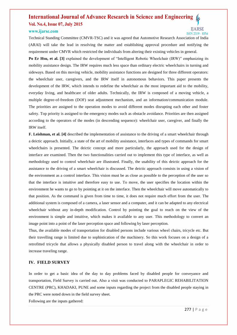
V. DESIGN CONSIDERATIONS
Design of frame and platform includes space considerations for wheelchair positioning and travel. Thus,
parameters such as length from wheel base of wheel chair to shoulder support, length from wheel base of wheel
chair to hand rest, width of wheel chair, total length of wheel chair were needed. Also to consider reach-ability
data of a disabled person sitting on the wheel chair was required [5]. For selecting the above parameters data
consideration is required. As per ADA standards [5], size of wheelchair has been taken as 1050mm x 750mm.
Reach-ability data is needed to finalize the positions of functional controls such as handle, brakes, accelerator
etc [2].
Fig.2 Range of Reach for Wheelchair User (All dimensions are in mm)[5]
279 | P a g e
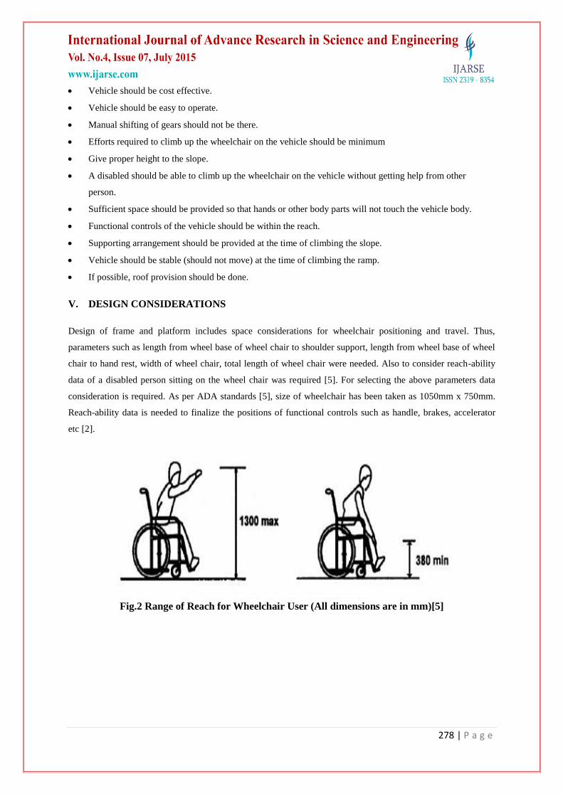
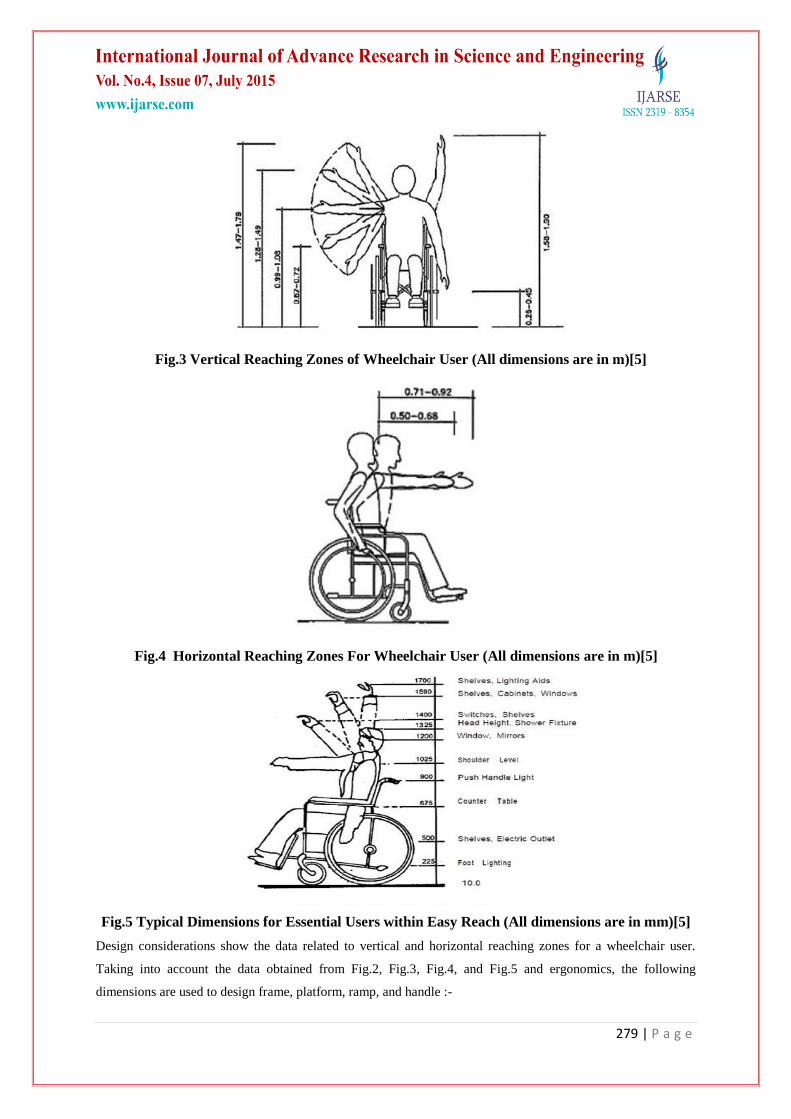
Fig.3 Vertical Reaching Zones of Wheelchair User (All dimensions are in m)[5]
Fig.4 Horizontal Reaching Zones For Wheelchair User (All dimensions are in m)[5]
Fig.5 Typical Dimensions for Essential Users within Easy Reach (All dimensions are in mm)[5]
Design considerations show the data related to vertical and horizontal reaching zones for a wheelchair user.
Taking into account the data obtained from Fig.2, Fig.3, Fig.4, and Fig.5 and ergonomics, the following
dimensions are used to design frame, platform, ramp, and handle :-
280 | P a g e
Length of platform = 1.1 m
Width of the platform = 0.8 m
Height of the hand rest = 0.75 m above the platform
Position of functional controls = 0.73 m above the platform
VI. MATERIAL SELECTION
While selecting the material for fabrication, prime motive is to select material that can provide high strength and
reliability to the tricycle. Another consideration is to reduce material cost and overall weight of tricycle. Some
desirable properties of material required for fabrication of model are [6]:-
1. Material must have high tensile strength.
2. Material should withstand torsional and shear stresses.
3. Material should be highly resistant to changing weather conditions.
4. Material should be light in weight.
5. Material should be cost-effective & cheap.
As the application includes various forces and moments on the fabricated model, the material selected must be
either metal rods or tubes for safety and efficient working. Mild Steel provides high tensile and torsional
strength (Refer Table No.1) required for the application. Hence, Mild Steel is selected .
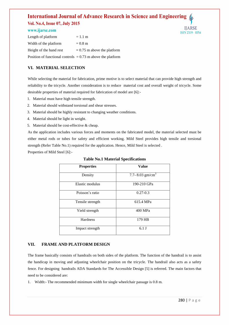
Properties of Mild Steel [6]:-
Table No.1 Material Specifications
Properties Value
Density 7.7- 8.03 gm/cm3
Elastic modulus 190-210 GPa
Poisson’s ratio 0.27-0.3
Tensile strength 615.4 MPa
Yield strength 400 MPa
Hardness 179 HB
Impact strength 6.1 J
VII. FRAME AND PLATFORM DESIGN
The frame basically consists of handrails on both sides of the platform. The function of the handrail is to assist
the handicap in moving and adjusting wheelchair position on the tricycle. The handrail also acts as a safety
fence. For designing handrails ADA Standards for The Accessible Design [5] is referred. The main factors that
need to be considered are:
1. Width:- The recommended minimum width for single wheelchair passage is 0.8 m.
281 | P a g e
2. Height:- The recommended height of the top of the handrail gripping surface is between 0.635 m and 0.762
m above floor surface.
3. The recommended diameter or width of the gripping surfaces of a handrail is 0.032 m to 0.038 m
7.1 Selection of Pipes
The size of a MS tube is selected on the basis of factor of safety consideration and reaction forces calculations.
A function of chassis is to make the vehicle robust and strong enough to withstand all the forces acting on the
vehicle. To determine the desirable size of pipe, it is necessary to find out the critical component in the vehicle
which is most likely to fail when impact occurred on wheels. Stresses developed in the pipe depend upon the
area of cross section of pipe. Larger the area, smaller the stress in the pipe. By considering available sizes of
pipe, maximum stresses developed in the critical component and factor of safety is calculated and the size which
gives maximum factor of safety is selected.
7.2 Calculations for Frame
When the vehicle hits an obstruction, impact force is transmitted to chassis through suspension spring. So, the
component on which suspension spring is mounted is the critical component.
Let,
F = Force that is transmitted through suspension system
θ = Angle made by the spring to vertical axis
Do = Outer diameter of the pipe
Di = Inner diameter of the pipe
Syt = Yield strength of the MS pipe
y = Position of neutral axis
I = Area moment of inertia
Assuming total impact force acting on the rear wheels of the vehicle in upward direction is "2g" times the
weight of the vehicle.
Here, θ = 30°
Total Force =2*9.81*250 (since weight of vehicle is 250 kg)
=4905 N
As two suspensions are given, force acting on each suspension is (F)=(Total force/2) = 2452.5 N
Vertical force acting on the pipe,
(Fv) = Fcos(θ) = Fcos(30) = 2123.927 N
Horizontal force acting on the pipe,
(Fh) = Fsin(θ) = Fsin(30) =1226.25 N
Length of the critical component of chassis is 0.38m, and it acts as a cantilever beam fixed at one point and load
is applied at the 0.19 m away from fixed point.
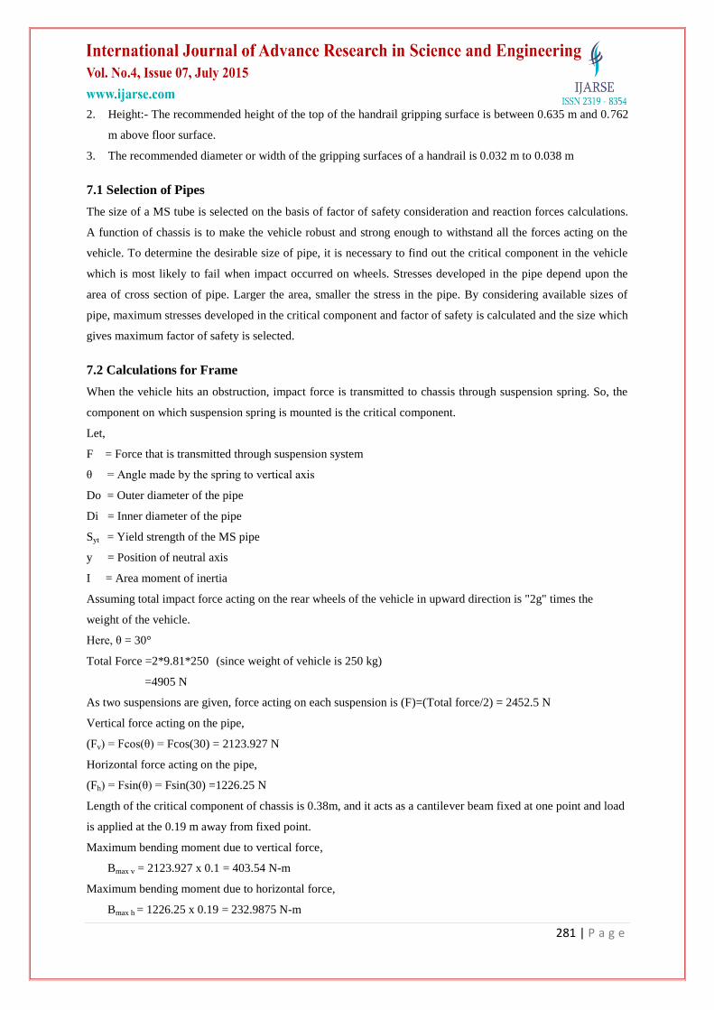
Maximum bending moment due to vertical force,
Bmax v = 2123.927 x 0.1 = 403.54 N-m
Maximum bending moment due to horizontal force,
Bmax h = 1226.25 x 0.19 = 232.9875 N-m
282 | P a g e
Resultant bending moment,
Bres = √(403.542 + 232.9875
2) = 465.94 N-m
Maximum bending stresses,
Fbmax. = Bresy
I
= 465.94 x (0.0381/2)
∏/64 (0.03814 - 0.0341
4)
= 239.89 N/mm2
Available factor of safety = (Syt / Maximum bending stress) = (400/239.89) = 1.66
Similarly FOS calculations are done for other types of pipes and results are tabulated in Table No. 2:
Table No. 2 Factor of Safety for Different Tubes
Pipe material Do, (mm) Di, (mm) Thickness
(mm) Max B.M. (Mpa) FOS
Mild steel 38.1 34.1 2 239.92 1.66
Mild steel 38.1 34.6 1.75 268.78 1.48
Mild steel 27.94 24.44 1.75 525.87 0.76
Mild steel 25.4 21.4 2 584.83 0.68
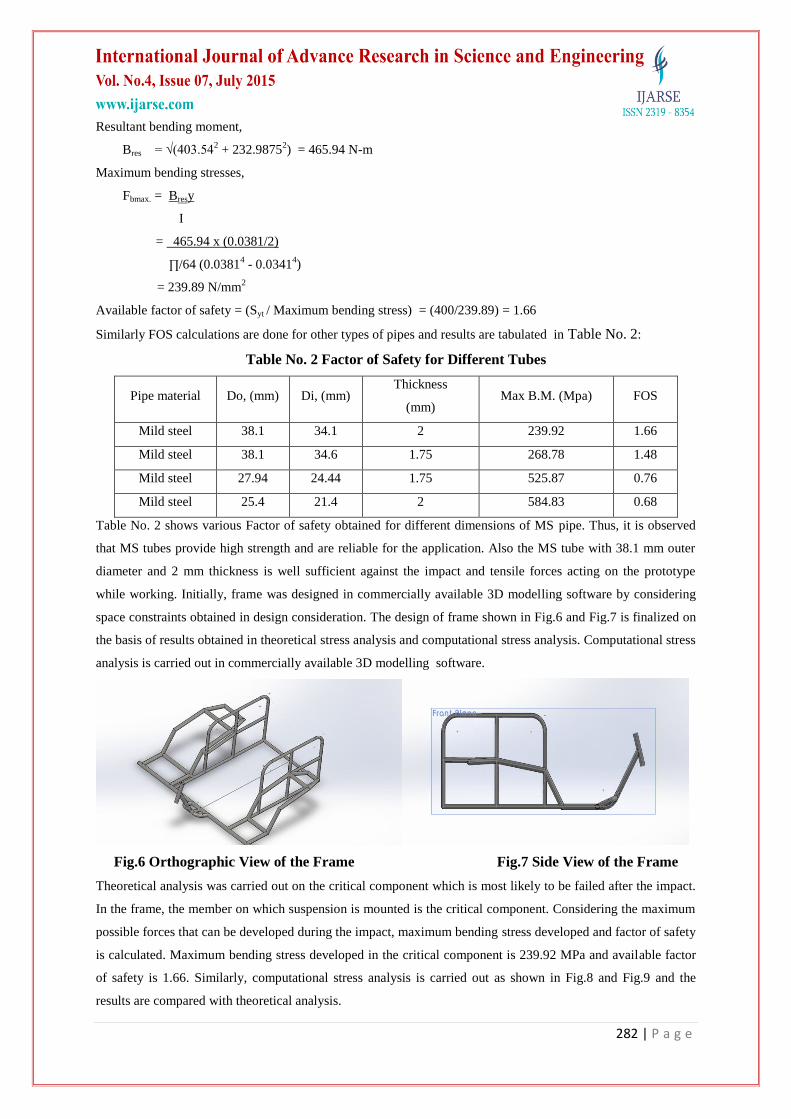
Table No. 2 shows various Factor of safety obtained for different dimensions of MS pipe. Thus, it is observed
that MS tubes provide high strength and are reliable for the application. Also the MS tube with 38.1 mm outer
diameter and 2 mm thickness is well sufficient against the impact and tensile forces acting on the prototype
while working. Initially, frame was designed in commercially available 3D modelling software by considering
space constraints obtained in design consideration. The design of frame shown in Fig.6 and Fig.7 is finalized on
the basis of results obtained in theoretical stress analysis and computational stress analysis. Computational stress
analysis is carried out in commercially available 3D modelling software.
Fig.6 Orthographic View of the Frame Fig.7 Side View of the Frame
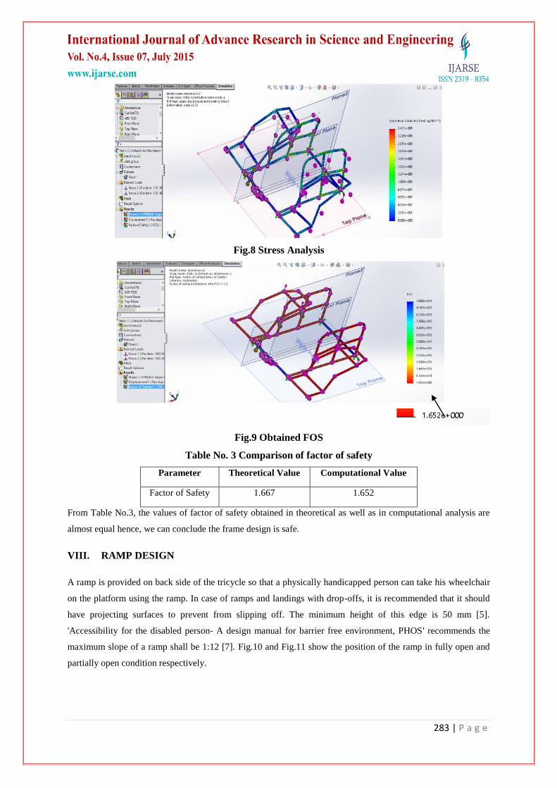
Theoretical analysis was carried out on the critical component which is most likely to be failed after the impact.
In the frame, the member on which suspension is mounted is the critical component. Considering the maximum
possible forces that can be developed during the impact, maximum bending stress developed and factor of safety
is calculated. Maximum bending stress developed in the critical component is 239.92 MPa and available factor
of safety is 1.66. Similarly, computational stress analysis is carried out as shown in Fig.8 and Fig.9 and the
results are compared with theoretical analysis.
283 | P a g e
Fig.8 Stress Analysis
Fig.9 Obtained FOS
Table No. 3 Comparison of factor of safety
Parameter Theoretical Value Computational Value
Factor of Safety 1.667 1.652
From Table No.3, the values of factor of safety obtained in theoretical as well as in computational analysis are
almost equal hence, we can conclude the frame design is safe.
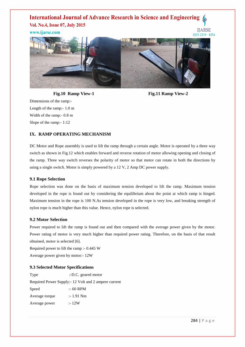
VIII. RAMP DESIGN
A ramp is provided on back side of the tricycle so that a physically handicapped person can take his wheelchair
on the platform using the ramp. In case of ramps and landings with drop-offs, it is recommended that it should
have projecting surfaces to prevent from slipping off. The minimum height of this edge is 50 mm [5].
'Accessibility for the disabled person- A design manual for barrier free environment, PHOS' recommends the
maximum slope of a ramp shall be 1:12 [7]. Fig.10 and Fig.11 show the position of the ramp in fully open and
partially open condition respectively.
284 | P a g e
Fig.10 Ramp View-1 Fig.11 Ramp View-2
Dimensions of the ramp:-
Length of the ramp:- 1.0 m
Width of the ramp:- 0.8 m
Slope of the ramp:- 1:12
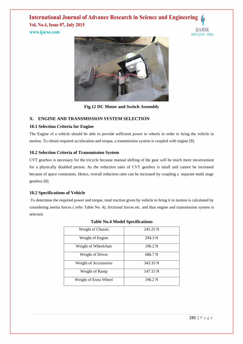
IX. RAMP OPERATING MECHANISM
DC Motor and Rope assembly is used to lift the ramp through a certain angle. Motor is operated by a three way
switch as shown in Fig.12 which enables forward and reverse rotation of motor allowing opening and closing of
the ramp. Three way switch reverses the polarity of motor so that motor can rotate in both the directions by
using a single switch. Motor is simply powered by a 12 V, 2 Amp DC power supply.
9.1 Rope Selection
Rope selection was done on the basis of maximum tension developed to lift the ramp. Maximum tension
developed in the rope is found out by considering the equilibrium about the point at which ramp is hinged.
Maximum tension in the rope is 100 N.As tension developed in the rope is very low, and breaking strength of
nylon rope is much higher than this value. Hence, nylon rope is selected.
9.2 Motor Selection
Power required to lift the ramp is found out and then compared with the average power given by the motor.
Power rating of motor is very much higher than required power rating. Therefore, on the basis of that result
obtained, motor is selected [6].
Required power to lift the ramp :- 0.445 W
Average power given by motor:- 12W
9.3 Selected Motor Specifications
Type :-D.C. geared motor
Required Power Supply:- 12 Volt and 2 ampere current
Speed :- 60 RPM
Average torque :- 1.91 Nm
Average power :- 12W
285 | P a g e
Fig.12 DC Motor and Switch Assembly
X. ENGINE AND TRANSMISSION SYSTEM SELECTION
10.1 Selection Criteria for Engine
The Engine of a vehicle should be able to provide sufficient power to wheels in order to bring the vehicle in
motion. To obtain required acceleration and torque, a transmission system is coupled with engine [8].
10.2 Selection Criteria of Transmission System
CVT gearbox is necessary for the tricycle because manual shifting of the gear will be much more inconvenient
for a physically disabled person. As the reduction ratio of CVT gearbox is small and cannot be increased
because of space constraints. Hence, overall reduction ratio can be increased by coupling a separate multi stage
gearbox [8].
10.2 Specifications of Vehicle
To determine the required power and torque, total traction given by vehicle to bring it in motion is calculated by
considering inertia forces ( refer Table No. 4), frictional forces etc. and thus engine and transmission system is
selected.
Table No.4 Model Specifications
Weight of Chassis 245.25 N
Weight of Engine 294.3 N
Weight of Wheelchair 196.2 N
Weight of Driver 686.7 N
Weight of Accessories 343.35 N
Weight of Ramp 147.15 N
Weight of Extra Wheel 196.2 N
286 | P a g e
Engine and transmission system specification are given in Table No. 5:-
Table No.5 Engine Specifications
Displacement 124.6 cc
Maximum Power 8.0 BHP @7500 RPM
Maximum Torque 9.0 N-M @5500 RPM
XI. SUSPENSION AND BRAKES
11.1 Selection of Suspension System [8]
When a tire hits an obstruction, the reaction force is developed and the suspension system tries to reduce this
force. The reaction force depends on the unsprung mass at each wheel assembly. Usually, the larger the ratio of
sprung weight to unsprung weight, the less the body and vehicle occupants are affected by bumps, dips, and
other surface irregularity. A large sprung weight to unsprung weight ratio can also impact the vehicle control.
In the tricycle, as the unsprung mass is lesser than the sprung mass so it is very efficient to use trailing arm
suspension system. If the double wishbone suspension is used then width of the vehicle will be slightly more
and cost will increase.
11.2 Brakes [8]
A brake is a mechanical device which inhibits motion, slowing or stopping a moving object or preventing its
motion. Most commonly, brakes use friction between two surfaces pressed together to convert the kinetic
energy of the moving object into heat. Drum brakes are used in the tricycle because the vehicle is a slow speed
application. Hence, high braking torque is not necessary and cost of the drum brakes is less.
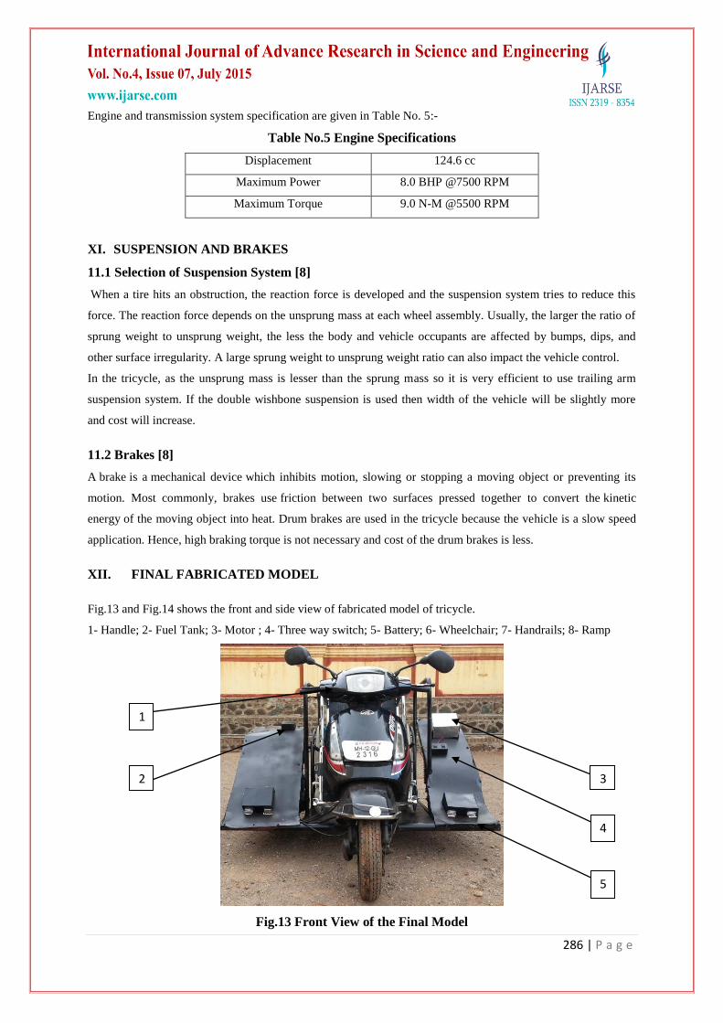
XII. FINAL FABRICATED MODEL
Fig.13 and Fig.14 shows the front and side view of fabricated model of tricycle.
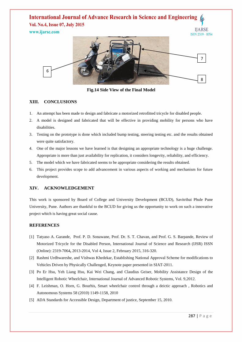
1- Handle; 2- Fuel Tank; 3- Motor ; 4- Three way switch; 5- Battery; 6- Wheelchair; 7- Handrails; 8- Ramp
Fig.13 Front View of the Final Model
1
2 3
5
4
287 | P a g e
Fig.14 Side View of the Final Model
XIII. CONCLUSIONS
1. An attempt has been made to design and fabricate a motorized retrofitted tricycle for disabled people.
2. A model is designed and fabricated that will be effective in providing mobility for persons who have
disabilities.
3. Testing on the prototype is done which included bump testing, steering testing etc. and the results obtained
were quite satisfactory.
4. One of the major lessons we have learned is that designing an appropriate technology is a huge challenge.
Appropriate is more than just availability for replication, it considers longevity, reliability, and efficiency.
5. The model which we have fabricated seems to be appropriate considering the results obtained.
6. This project provides scope to add advancement in various aspects of working and mechanism for future
development.
XIV. ACKNOWLEDGEMENT
This work is sponsored by Board of College and University Development (BCUD), Savitribai Phule Pune
University, Pune. Authors are thankful to the BCUD for giving us the opportunity to work on such a innovative
project which is having great social cause.
REFERENCES
[1] Tatyaso A. Garande, Prof. P. D. Sonawane, Prof. Dr. S. T. Chavan, and Prof. G. S. Barpande, Review of
Motorized Tricycle for the Disabled Person, International Journal of Science and Research (IJSR) ISSN
(Online): 2319-7064, 2013-2014, Vol 4, Issue 2, February 2015, 316-320.
[2] Rashmi Urdhwareshe, and Vishwas Khedekar, Establishing National Approval Scheme for modifications to
Vehicles Driven by Physically Challenged, Keynote paper presented in SIAT-2011.
[3] Po Er Hsu, Yeh Liang Hsu, Kai Wei Chang, and Claudius Geiser, Mobility Assistance Design of the
Intelligent Robotic Wheelchair, International Journal of Advanced Robotic Systems, Vol. 9,2012.
[4] F. Leishman, O. Horn, G. Bourhis, Smart wheelchair control through a deictic approach , Robotics and
Autonomous Systems 58 (2010) 1149-1158, 2010
[5] ADA Standards for Accessible Design, Department of justice, September 15, 2010.
6
7
8
288 | P a g e
[6] V.B. Bhandari, Design of Machine Elements (Tata McGraw Hill Pvt. Ltd., New Delhi, Third Edition,
2013).
[7] PHOS, Accessibility for the disabled person- A design manual for barrier free environment, Belgium
[8] Dr. Kirpal Singh, Automobile Engineering Vol I and Vol II (Standard Publishers Distributors, New Delhi,
12th Edition, 2011).