Embed Size (px)
Citation preview
HAL Id: inria-00000562https://hal.inria.fr/inria-00000562
Submitted on 27 Aug 2007
HAL is a multi-disciplinary open accessarchive for the deposit and dissemination of sci-entific research documents, whether they are pub-lished or not. The documents may come fromteaching and research institutions in France orabroad, or from public or private research centers.
L’archive ouverte pluridisciplinaire HAL, estdestinée au dépôt et à la diffusion de documentsscientifiques de niveau recherche, publiés ou non,émanant des établissements d’enseignement et derecherche français ou étrangers, des laboratoirespublics ou privés.
Design of automotive X-by-Wire systemsCédric Wilwert, Nicolas Navet, Ye-Qiong Song, Françoise Simonot-Lion
To cite this version:Cédric Wilwert, Nicolas Navet, Ye-Qiong Song, Françoise Simonot-Lion. Design of automotive X-by-Wire systems. Richard Zurawski. The Industrial Communication Technology Handbook, CRC Press,2005, 0849330777. <inria-00000562>

Design of automotive X-by-Wire systems
Cédric Wilwert PSA Peugeot - Citroën 92000 La Garenne Colombe - France Fax: +33 3 83 58 17 01 Phone: +33 3 83 58 17 17 [email protected] Nicolas Navet LORIA UMR 7503 – INRIA Campus Scientifique - BP 239 - 54506 VANDOEUVRE-lès-NANCY CEDEX Fax: +33 3 83 58 17 01 Phone : +33 3 83 58 17 61 [email protected] Ye Qiong Song LORIA UMR 7503 – Université Henri Poincaré Nancy I Campus Scientifique - BP 239 - 54506 VANDOEUVRE-lès-NANCY CEDEX Fax: +33 3 83 58 17 01 Phone : +33 3 83 58 17 64 [email protected] Françoise Simonot-Lion LORIA UMR 7503 – Institut National Polytechnique de Lorraine Campus Scientifique - BP 239 - 54506 VANDOEUVRE-lès-NANCY CEDEX Fax: +33 3 83 27 83 19 Phone : +33 3 83 58 17 62 [email protected] CONTENTS Design of automotive X-by-Wire systems ....................................................................................................... 1
Abstract : ............................................................................................................................................................... 2
1 Why X-by-Wire systems ?.......................................................................................................................... 3
1.1 Steer-by-Wire system .......................................................................................................................... 4
1.2 Brake-by-Wire systems ....................................................................................................................... 4
2 Problem, context and constraints for the design of X-by-Wire systems .............................................. 5
2.1 General constraints............................................................................................................................... 5
2.2 Dependability constraints.................................................................................................................... 6
2.3 Real-time constraints ........................................................................................................................... 7
3 Fault-tolerant services for X-by-Wire ....................................................................................................... 7
1
3.1 Overview on the communication services ........................................................................................ 7
3.1.1 Time-Triggered communication ................................................................................................ 8
3.1.2 Fault Tolerant Unit (FTU)........................................................................................................... 8
3.1.3 Fail-Silent Node............................................................................................................................ 9
3.1.4 Bus Guardian ................................................................................................................................ 9
3.2 Main time-triggered protocols for automotive industry................................................................ 10
3.2.1 TTP/C........................................................................................................................................... 10
3.2.2 FlexRay........................................................................................................................................ 11
3.2.3 TTCAN ........................................................................................................................................ 13
3.3 Operating Systems and middleware services ................................................................................. 14
3.3.1 OSEKTime.................................................................................................................................. 15
3.3.2 FTCom......................................................................................................................................... 15
4 Steer-by-Wire architecture: a case study ................................................................................................ 16
4.1 Functional description of a Steer-by-Wire system ........................................................................ 16
4.2 Dependability and real-time properties ........................................................................................... 17
4.3 Operational architecture .................................................................................................................... 18
4.4 Dependability issues .......................................................................................................................... 20
4.4.1 Failure Model.............................................................................................................................. 20
4.4.2 Operational architecture vs dependability requirements....................................................... 22
4.4.3 Redundancy and diversification ............................................................................................... 23
4.4.4 Configuration of the communication protocol ....................................................................... 24
4.4.5 Evaluation of the Behavioral Reliability of the Architecture............................................... 26
5 Conclusion................................................................................................................................................... 32
References ........................................................................................................................................................... 32
Abstract :
X-by-Wire is a generic term referring to the replacement of mechanical or hydraulic systems, such as
braking or steering, by electronic ones. In this chapter, we analyze the real-time and dependability
2
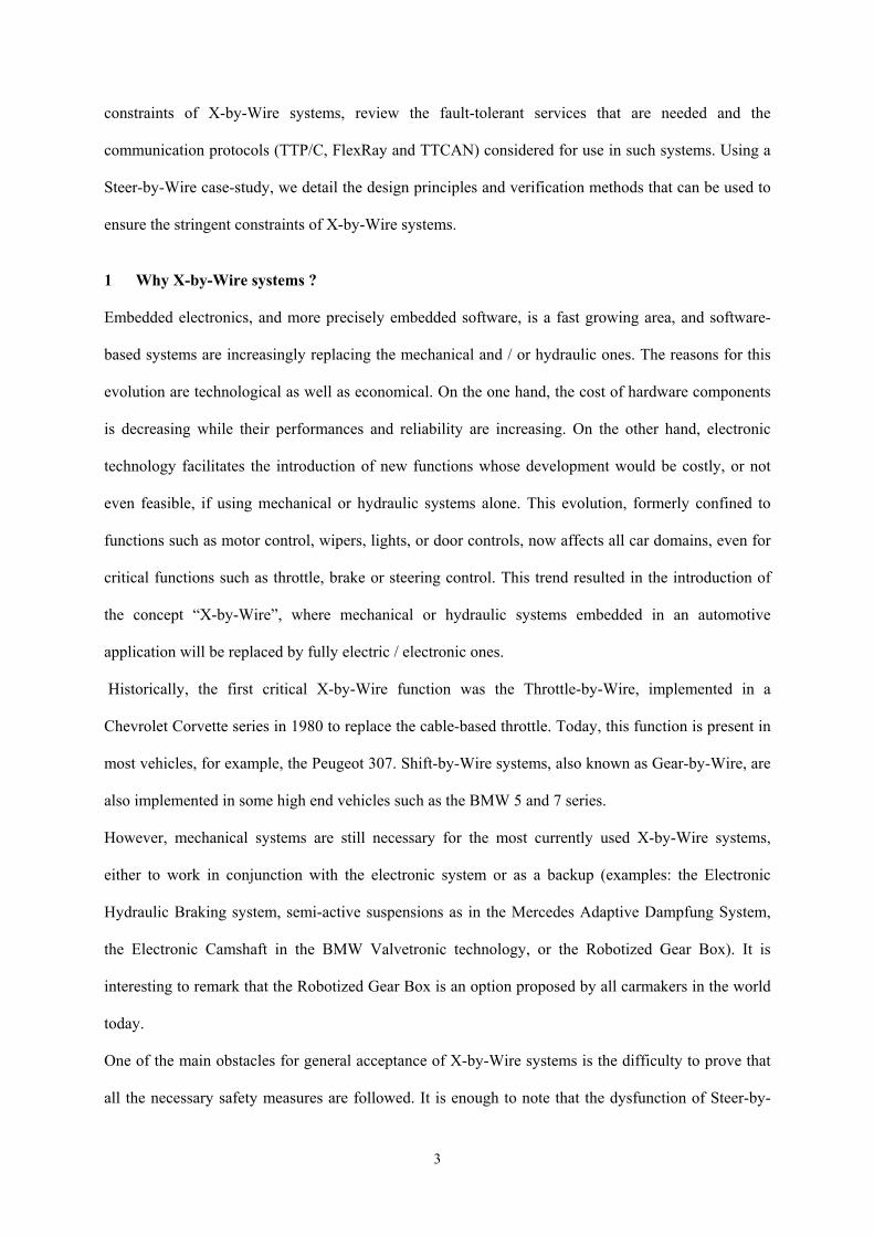
constraints of X-by-Wire systems, review the fault-tolerant services that are needed and the
communication protocols (TTP/C, FlexRay and TTCAN) considered for use in such systems. Using a
Steer-by-Wire case-study, we detail the design principles and verification methods that can be used to
ensure the stringent constraints of X-by-Wire systems.
1 Why X-by-Wire systems ?
Embedded electronics, and more precisely embedded software, is a fast growing area, and software-
based systems are increasingly replacing the mechanical and / or hydraulic ones. The reasons for this
evolution are technological as well as economical. On the one hand, the cost of hardware components
is decreasing while their performances and reliability are increasing. On the other hand, electronic
technology facilitates the introduction of new functions whose development would be costly, or not
even feasible, if using mechanical or hydraulic systems alone. This evolution, formerly confined to
functions such as motor control, wipers, lights, or door controls, now affects all car domains, even for
critical functions such as throttle, brake or steering control. This trend resulted in the introduction of
the concept “X-by-Wire”, where mechanical or hydraulic systems embedded in an automotive
application will be replaced by fully electric / electronic ones.
Historically, the first critical X-by-Wire function was the Throttle-by-Wire, implemented in a
Chevrolet Corvette series in 1980 to replace the cable-based throttle. Today, this function is present in
most vehicles, for example, the Peugeot 307. Shift-by-Wire systems, also known as Gear-by-Wire, are
also implemented in some high end vehicles such as the BMW 5 and 7 series.
However, mechanical systems are still necessary for the most currently used X-by-Wire systems,
either to work in conjunction with the electronic system or as a backup (examples: the Electronic
Hydraulic Braking system, semi-active suspensions as in the Mercedes Adaptive Dampfung System,
the Electronic Camshaft in the BMW Valvetronic technology, or the Robotized Gear Box). It is
interesting to remark that the Robotized Gear Box is an option proposed by all carmakers in the world
today.
One of the main obstacles for general acceptance of X-by-Wire systems is the difficulty to prove that
all the necessary safety measures are followed. It is enough to note that the dysfunction of Steer-by-
3
Wire, Brake-by-Wire or Throttle-by-Wire systems would jeopardize the safety of the occupants. As
seen before, a number of X-by-Wire systems have already been implemented in certain series of
vehicles, however, Steer-by-Wire and Brake-by-Wire systems will always have a mechanical backup.
The concern for safety is certainly a major factor.
Another obstacle is that the customer’s demand is not very great at the moment; he does not realize the
technical advantages and only sees a higher price tag. But, the advantages of this technology can be
very attractive for both carmakers and customers (see sections 1.1 and 1.2), which explains why
carmakers are investing in this domain.
1.1 Steer-by-Wire system
The first advantage lies in the decreased risk of the steering column entering the cockpit in the event of
a frontal crash. Furthermore, the variable steering ratio of the Steer-by-Wire system brings a
remarkably increased comfort to the driver. This function enables the steering ratio between the hand
wheel and the wheels to adapt according to the driving conditions. In parking and urban driving, this
ratio should be smaller in order to reduce the amplitude of the hand wheel rotation. Another facility for
steering functionality, brought by software-based technology, is the µ-split braking which consists in
applying a dissymmetric torque to the wheels in case of a dissymmetric adherence. Finally, the
steering column is one of the heaviest components of the vehicle and removing it significantly
decreases the weight of the vehicle and thus reduces fuel consumption.
Among the drawbacks, the electrical power needed to action the front axle requires the use of 42 Volt
technology. At the SAE Conference in 2003 [1], it was said that this technology would not be mature
before 2010. This announcement has considerably reduced the emphasis put on the X-by-Wire
developments in general. Furthermore, the safety issues have not yet been fully defined.
1.2 Brake-by-Wire systems
A Brake-by-Wire system implemented with one micro-controller and one actuator per wheel can
significantly increase the quality of the braking, in particular, by reducing the stopping distance.
Moreover, this technology provides more precise braking by adapting to the pressure the driver puts
4
on the pedal. Like Steer-by-Wire, there is a significant decrease in the weight of the vehicle in
removing the hydraulic braking system and, therefore, significantly lowering costs. Finally, Brake-by-
Wire will help to protect the environment because no braking fluid is necessary.
Unfortunately, as with the Steer-by-Wire system, the 42Volt problem is a barrier for its present
deployment. Another hindrance comes from the mentality of the customers. Indeed, the customer is
faced with a new technology for a critical function that will be more expensive in the beginning and
whose benefits he does not clearly see.
The first technology in Brake-by-Wire was the introduction of Electro Hydraulic Braking (EHB). The
main difference between the EHB system and the classic braking system is that each wheel has an
independent braking subsystem: the hydraulic pressure is applied independently on each wheel.
However, a classic hydraulic circuit is still implemented from the pedal to the front wheels for safety
reasons. The EHB system was factory installed for the first time in 2001 with the Mercedes Roadster
SL. Today, Toyota proposes a “regenerative EHB” in their Prius, which uses the energy dissipated
during deceleration to charge the battery.
2 Problem, context and constraints for the design of X-by-Wire systems
2.1 General constraints
As explained before, some X-by-Wire systems are already standard in certain series. However, while
the implementation of Brake-by-Wire and Steer-by-Wire is possible with a 14 Volt battery in low
weight vehicles, this is not the case for the heavier ones. As the first Brake-by-Wire and Steer-by-Wire
will be costly in the beginning, they have greater chances of being implemented in high-end vehicles.
Consequently, 42 Volt technology has to be mature before X-by-Wire systems can be mass produced.
Moreover, Cell Fuel Technology, with fully electric energy sources, seems to be well situated for
replacing combustion engines. This significantly reduces the necessity of 42 Volt technology in the
long run [1].
In addition, the size of the X-by-Wire systems and their cost are major constraints for carmakers;
electronics-based systems already account for 30% of the total cost in current vehicles.
5
2.2 Dependability constraints
An analysis of the requirements for X-by-Wire systems was published in the conclusions of the X-by-
Wire Esprit project 19]. In general, for a critical X-by-Wire system, it must be ensured that [19]:
- a system failure does not lead to a state in which human life, economics or
environment are endangered,
- and a single failure of one component must not lead to a failure of the whole X-by-
Wire system.
The system shall memorize intermittent failures and it shall signal a critical failure to the driver, for
example through a lightning on the dashboard.. Moreover, it is required that the system is at least able
to tolerate one major critical fault without loss of the functionality for a time long enough to reach a
safe parking area. This requirement is a very constraining one, because if only two redundant
components are used to provide a critical function, in case of failure of one of these components, the
driver must immobilize the vehicle. This requirement will have to be confronted to the availability
requirements in the future.
In terms of the criticality of the involved functions, automotive X-by-Wire systems can reasonably be
compared with Flight-by-Wire systems in the avionic field. According to [19], the probability of
encountering a critical safety failure shall not exceed 5⋅10-10 per hour and per system, but other studies
have been realized with a maximal bound of 10-9. This quantification can be translated in terms of
Safety Integrity Level (SIL, see [2]) and a maximal bound of 10-9 corresponds to a SIL4 system. In
fact, SIL4 conformance is reached below 10-8.
Up to now, it has been a challenge to reach such dependability because of the lack of experience in the
automotive industry with X-by-Wire systems and because of the complexity of the problem. In
particular, the environment (EMI, temperature peaks, ..) may reduce the predictability of the system
and the design is subject to heavy cost and weight constraints. It is likely that, as in the aeronautic
industry, for legal and technical reasons, the design process (e.g., software development, methods and
tools for validation, ...) will have to be certified in the future.
6
Finally, one objective that must be reached is that an X-by-Wire system offers the same availability
and the same maintainability as their mechanical/hydraulic counterparts. The challenge is to prove that
a given X-by-Wire system adheres to all these requirements.
2.3 Real-time constraints
Belonging to the chassis domain, Steer-by-Wire and Brake-by-Wire systems are intrinsically real-time
distributed systems. They implement complex multivariable control laws and deliver real-time
information to intelligent devices that are physically distant (for example, the four wheels). They have
to respect stringent time constraints, such as a sampling period of only a few milliseconds. End-to-end
response times shall also be bounded, for example, the time between a request from the driver and the
response of the physical system must be lower than a few tens of milliseconds (see the Steer-by-Wire
example in section 4). An excessive end-to-end response time of a control loop may induce not only
performance degradation but also cause the instability of the vehicle.
Although these constraints may differ according to the driving conditions, they all have to be respected
whatever the situation. So, in general, the worst case scenario must be taken into consideration and
these real-time constraints must be met with a high probability, even if the system is under random
perturbations, because of the critical safety nature of the X-by-Wire applications.
3 Fault-tolerant services for X-by-Wire
3.1 Overview on the communication services
The communication system has to provide services that are pertinent with respect to the dependability
objectives of the application (see section 2). For instance, the knowledge of the stations that are
operational at a given time is usually needed by X-by-Wire applications and thus, a membership
service that furnishes this information will ease the development of application-level software and its
accuracy.
7
3.1.1 Time-Triggered communication
Among communication networks, one distinguishes time-triggered protocols where activities are
driven by the progress of time and event-triggered protocols where activities are driven by the
occurrence of events. Both types of communication have advantages but one considers that, in general,
dependability is much easier to ensure using a time-triggered bus (refer, for instance, to [3] for a
discussion on this topic). This explains that, currently, only time-triggered communication systems are
being considered for use in X-by-Wire applications. In this category, multi-access protocols based on
TDMA (Time Division Multiple Access) are particularly well suited; they provide deterministic access
to the medium (the order of the transmissions is defined statically at the design time and organized in
“rounds”), and thus bounded response times. Moreover, their regular message transmissions can be
used as “heartbeats” for detecting station failures.
The two TDMA based networks that are candidates for supporting X-by-Wire applications are TTP/C
(see 3.2.1) and FlexRay (see 3.2.2). At the time of writing, FlexRay, which is backed by the major
players of the European automotive industry, seems in a strong position for becoming the standard in
the industry, although the specifications are not yet finalized.
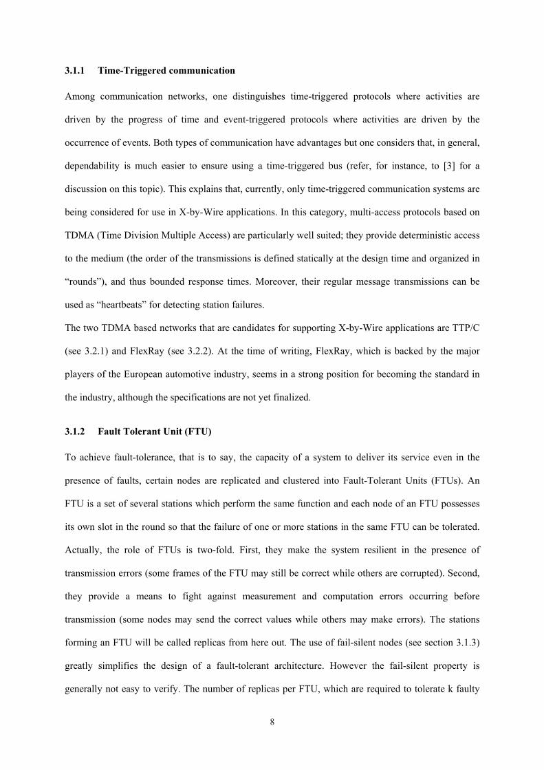
3.1.2 Fault Tolerant Unit (FTU)
To achieve fault-tolerance, that is to say, the capacity of a system to deliver its service even in the
presence of faults, certain nodes are replicated and clustered into Fault-Tolerant Units (FTUs). An
FTU is a set of several stations which perform the same function and each node of an FTU possesses
its own slot in the round so that the failure of one or more stations in the same FTU can be tolerated.
Actually, the role of FTUs is two-fold. First, they make the system resilient in the presence of
transmission errors (some frames of the FTU may still be correct while others are corrupted). Second,
they provide a means to fight against measurement and computation errors occurring before
transmission (some nodes may send the correct values while others may make errors). The stations
forming an FTU will be called replicas from here out. The use of fail-silent nodes (see section 3.1.3)
greatly simplifies the design of a fault-tolerant architecture. However the fail-silent property is
generally not easy to verify. The number of replicas per FTU, which are required to tolerate k faulty
8
components, depend on the behavior of the individual components (see [4]). For instance, if the failure
of k nodes must be tolerated, then the least necessary number of replicated nodes is k+1 when all
nodes are fail-silent.
3.1.3 Fail-Silent Node
As previously explained, fail-silent nodes greatly decrease the complexity of the design of a critical
application. A node is said fail-silent if:
1. a) it sends frames at the correct point in time (correctness in the time domain), and b) the
correct value is transmitted (correctness in the value domain), or
2. it sends detectably incorrect frames (e.g., wrong Cyclic Redundancy Check - CRC) in its
own slot or no frame at all.
A communication system, such as TTP/C, is able to provide very reliable support for the requirements
1.a) and 2) (which provide the so-called “fail-silence in the temporal domain” once they are
accomplished), especially through the bus guardian concept, while the value domain is mainly the
responsibility of the application. The reader is referred to [4, 5, 6] for good starting points on the
difficult problem of ensuring fail-silence
3.1.4 Bus Guardian
When communications are multiplexed, it may happen that a faulty ECU, transmitting outside its
specification, for instance, at the wrong time or with a larger frame, perturbs the correct functioning of
the whole network. One well-known manifestation is the so-called “babbling idiots” nodes that
transmits continuously. To avoid this situation, a component called the “bus guardian”, restricts the
controller’s ability to transmit by allowing transmission only when the node exhibits a specified
behavior. Ideally, the bus guardian should have its own copy of the schedule, it should be physically
separated from the controller, it should possess its own power supply and it should be able to construct
the global time itself. Due to the strong pressure from the automotive industry concerning costs, these
assumptions are not fulfilled in general, which reduces the efficiency of the bus guardian strategy.
9
3.2 Main time-triggered protocols for automotive industry
3.2.1 TTP/C
The TTP/C protocol (Time Triggered Protocol), which is defined in [7], is a central part of the Time-
Triggered Architecture (TTA – see [8]) and it possesses numerous features and services related to
dependability such as the bus guardian (see [5]), the group membership algorithm (see [9]) and
support for mode changes (see [10]). The TTA and the TTP/C protocols have been designed and
extensively studied at the Vienna University of Technology. Hardware implementations of the TTP/C
protocol, as well as software tools for the design of the application, are commercialized by the TTTech
company [11] and available today.
On a TTP/C network, the transmission support is replicated and each channel transports its own copy
of the same message. Although an Electro Magnetic Interference (EMI) is likely to affect both
channels in quite a similar manner, the redundancy provides some resilience to transmission errors
(see section 4.4.4) TTP/C can be implemented with a bus topology or a star topology. The latter
topology provides better fault tolerance since the star can act as a central bus guardian and protect
against errors that cannot be avoided by a local bus guardian such as spatial proximity fault. For
instance, a star topology is more resilient to spatial proximity faults and to faults due to a
desynchronization of an ECU (see section 3.1.4). To avoid a single point of failure, a dual star
topology shall be used with the drawback that the length of the cables is significantly increased.
At the Medium Access (MAC) level, the TTP/C protocol implements the synchronous TDMA
scheme: the stations (or nodes) have access to the bus in a strict deterministic sequential order and
each station possesses the bus for a constant period of time called a “slot” during which it has to
transmit one frame. The sequence of slots such that all stations have accessed the bus one time, is
called a “TDMA round”. An example of a round is shown in Figure . The size of the slot is not
necessarily identical for all stations in the TDMA round, but successive slots belonging to the same
station are of the same size. Consecutive TDMA rounds may differ by the data transmitted during the
slots, and the sequence of all TDMA rounds is the “cluster cycle” which repeats itself in a cycle.
10

TTP/C includes powerful but complex algorithms for easing and speeding up the design of fault-
tolerant applications and some of them have been formally verified (see for instance [9] and [12]). In
particular, TTP/C implements a clique avoidance algorithm and a membership algorithm that also
provides data acknowledgment. The fault hypothesis used for the design of TTP/C is well specified
and also quite restrictive (two successive faults must occur at least two rounds apart). Situations
outside the fault hypothesis are treated using “never give up” (NUP) strategies [3] which aim to
continue operation in a degredaded mode. For example, an usual method is that each node switches to
local control according to the information still available, while trying to return to the normal mode.
3.2.2 FlexRay
A consortium of major companies from the automotive field is currently developing the FlexRay
protocol. The core members are BMW, Bosch, DaimlerChrysler, General Motors, Motorola, Philips
and Volkswagen. The specifications of the FlexRay Protocol are not publicly available nor finalized at
the time of writing, however, material describing the protocol is available on the FlexRay web site
[13].
The FlexRay network is very flexible with regard to topology and transmission support redundancy. It
can be configured as a bus, a star or multi-stars and it is not mandatory that each station possess
replicated channels, even though this should be the case for X-by-Wire functions.
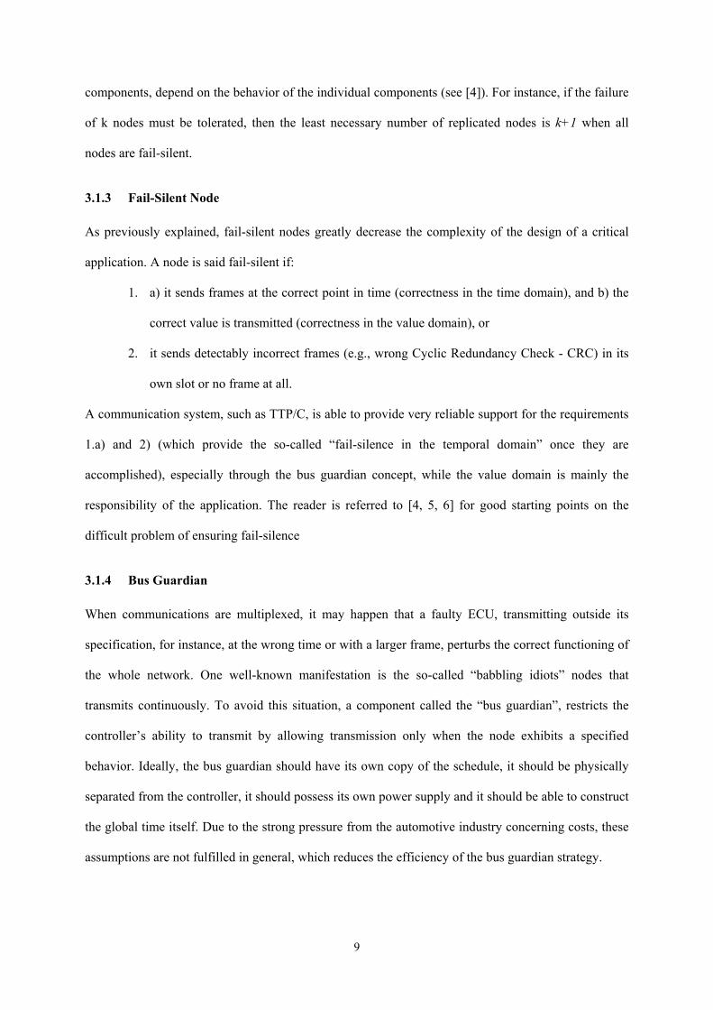
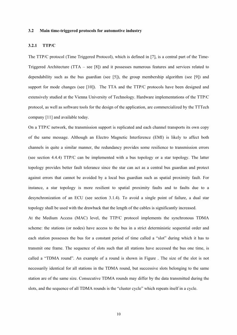
At the MAC level, FlexRay defines a communication cycle as the concatenation of a time-triggered
(or static) window and an event triggered (or dynamic) window. In each communication window,
whose size is set statically at design time, a different protocol is applied. The communication cycles
are executed periodically. The time-triggered window uses a TDMA MAC protocol; the main
difference with TTP/C is that a station might possess several slots in the time-triggered window, but
the size of all slots is identical. In the event-triggered part of the communication cycle, the protocol is
FTDMA (Flexible Time Division Multiple Access): the time is divided into so-called mini-slots, each
station possesses a given number of mini-slots (not necessarily consecutive) and it can start the
transmission of a frame inside each of its own mini-slots. A mini-slot remains idle if the station has
11
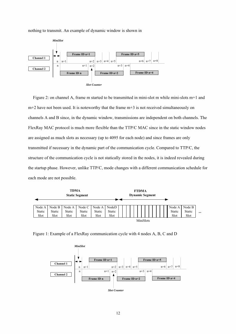
nothing to transmit. An example of dynamic window is shown in
Slot Counter
Channel 1
Channel 2
n n+1 n+2n+2
Frame ID n+1
n
Frame ID n
n+1
Frame ID n+2
n+3
MiniSlot
n+4 n+5
Frame ID n+5
n+3
Frame ID n+4
n+6n+4
n+7 n+8
Figure 2: on channel A, frame m started to be transmitted in mini-slot m while mini-slots m+1 and
m+2 have not been used. It is noteworthy that the frame m+3 is not received simultaneously on
channels A and B since, in the dynamic window, transmissions are independent on both channels. The
FlexRay MAC protocol is much more flexible than the TTP/C MAC since in the static window nodes
are assigned as much slots as necessary (up to 4095 for each node) and since frames are only
transmitted if necessary in the dynamic part of the communication cycle. Compared to TTP/C, the
structure of the communication cycle is not statically stored in the nodes, it is indeed revealed during
the startup phase. However, unlike TTP/C, mode changes with a different communication schedule for
each mode are not possible.
...Node BStaticSlot
NodeDStaticSlot
Node AStaticSlot
Node CStaticSlot
Node AStaticSlot
Node AStaticSlot
Static SegmentTDMA
Node BStaticSlot
Node AStaticSlot
Dynamic SegmentFTDMA
MiniSlots
Figure 1: Example of a FlexRay communication cycle with 4 nodes A, B, C and D
Slot Counter
Channel 1
Channel 2
n n+1 n+2n+2
Frame ID n+1
n
Frame ID n
n+1
Frame ID n+2
n+3
MiniSlot
n+4 n+5
Frame ID n+5
n+3
Frame ID n+4
n+6n+4
n+7 n+8
12
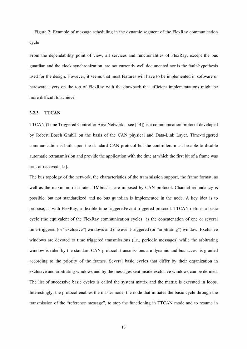
Figure 2: Example of message scheduling in the dynamic segment of the FlexRay communication
cycle
From the dependability point of view, all services and functionalities of FlexRay, except the bus
guardian and the clock synchronization, are not currently well documented nor is the fault-hypothesis
used for the design. However, it seems that most features will have to be implemented in software or
hardware layers on the top of FlexRay with the drawback that efficient implementations might be
more difficult to achieve.
3.2.3 TTCAN
TTCAN (Time Triggered Controller Area Network – see [14]) is a communication protocol developed
by Robert Bosch GmbH on the basis of the CAN physical and Data-Link Layer. Time-triggered
communication is built upon the standard CAN protocol but the controllers must be able to disable
automatic retransmission and provide the application with the time at which the first bit of a frame was
sent or received [15].
The bus topology of the network, the characteristics of the transmission support, the frame format, as
well as the maximum data rate - 1Mbits/s - are imposed by CAN protocol. Channel redundancy is
possible, but not standardized and no bus guardian is implemented in the node. A key idea is to
propose, as with FlexRay, a flexible time-triggered/event-triggered protocol. TTCAN defines a basic
cycle (the equivalent of the FlexRay communication cycle) as the concatenation of one or several
time-triggered (or “exclusive”) windows and one event-triggered (or “arbitrating”) window. Exclusive
windows are devoted to time triggered transmissions (i.e., periodic messages) while the arbitrating
window is ruled by the standard CAN protocol: transmissions are dynamic and bus access is granted
according to the priority of the frames. Several basic cycles that differ by their organization in
exclusive and arbitrating windows and by the messages sent inside exclusive windows can be defined.
The list of successive basic cycles is called the system matrix and the matrix is executed in loops.
Interestingly, the protocol enables the master node, the node that initiates the basic cycle through the
transmission of the “reference message”, to stop the functioning in TTCAN mode and to resume in
13
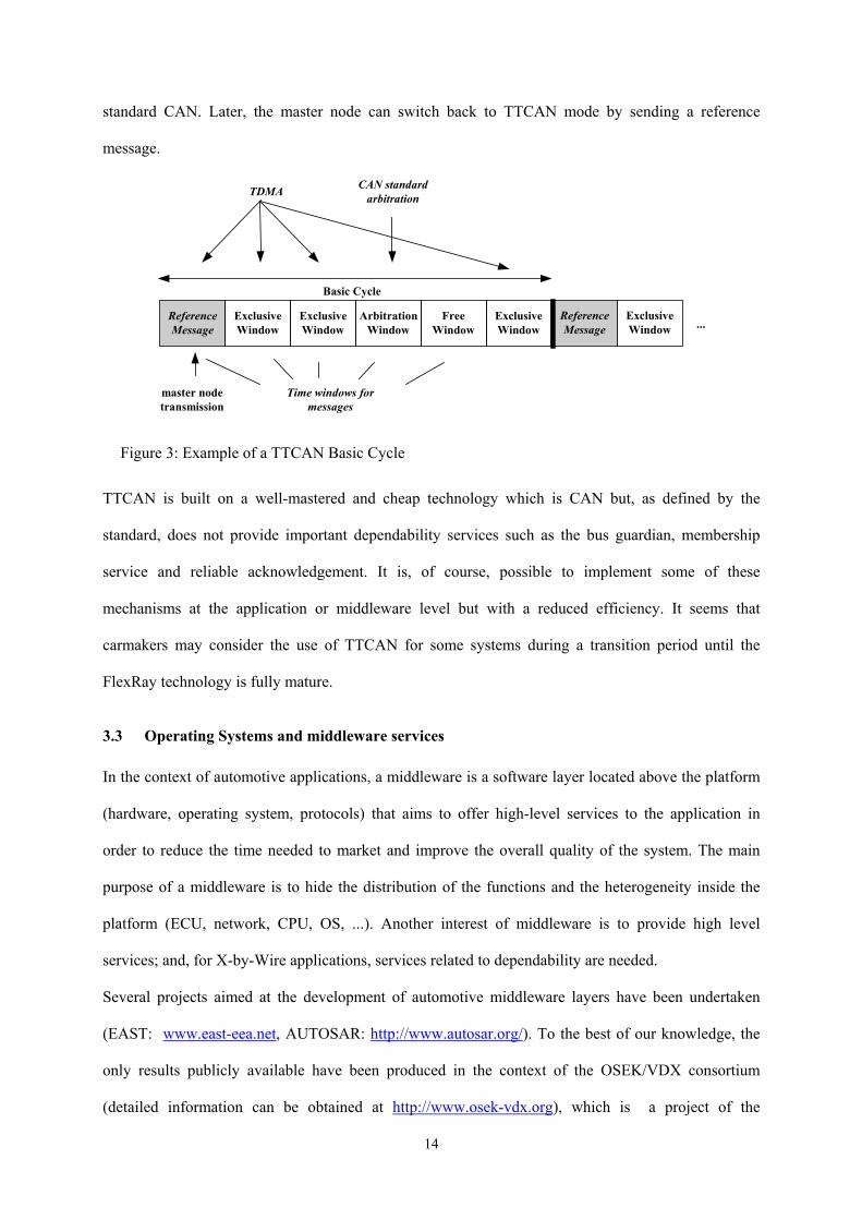
standard CAN. Later, the master node can switch back to TTCAN mode by sending a reference
message.
ExclusiveWindow
Time windows formessages
...ExclusiveWindow
ExclusiveWindow
ArbitrationWindow
ReferenceMessage
ExclusiveWindow
ReferenceMessage
master nodetransmission
TDMA CAN standardarbitration
FreeWindow
Basic Cycle
Figure 3: Example of a TTCAN Basic Cycle
TTCAN is built on a well-mastered and cheap technology which is CAN but, as defined by the
standard, does not provide important dependability services such as the bus guardian, membership
service and reliable acknowledgement. It is, of course, possible to implement some of these
mechanisms at the application or middleware level but with a reduced efficiency. It seems that
carmakers may consider the use of TTCAN for some systems during a transition period until the
FlexRay technology is fully mature.
3.3 Operating Systems and middleware services
In the context of automotive applications, a middleware is a software layer located above the platform
(hardware, operating system, protocols) that aims to offer high-level services to the application in
order to reduce the time needed to market and improve the overall quality of the system. The main
purpose of a middleware is to hide the distribution of the functions and the heterogeneity inside the
platform (ECU, network, CPU, OS, ...). Another interest of middleware is to provide high level
services; and, for X-by-Wire applications, services related to dependability are needed.
Several projects aimed at the development of automotive middleware layers have been undertaken
(EAST: www.east-eea.net, AUTOSAR: http://www.autosar.org/). To the best of our knowledge, the
only results publicly available have been produced in the context of the OSEK/VDX consortium
(detailed information can be obtained at http://www.osek-vdx.org), which is a project of the
14
automotive industry whose objective is to build a standard architecture for in-vehicle control units.
Among the results of the OSEK/VDX group, two are of particular interest for X-by-Wire: the
OSEKTime operating and the Fault-Tolerant Communication layer.
3.3.1 OSEKTime
OSEKTime OS (OSEK/VDX Time-Triggered Operating Systems, see [16]) is a small operating
system designed to offer the basic services needed by time-triggered applications. In particular,
OSEKTime OS offers services for task management, interrupt processing and error handling.
An offline-generated dispatcher table, termed a “dispatcher round”, activates the tasks in a determined
order and repeats itself as long as the system is running. Several different dispatcher tables,
corresponding, for instance, to different functioning modes of the system, can be defined, but the
switching from one table to the next can only take place at the end of a round.
Tasks cannot be blocked waiting for an external event but they can be preempted; a running task will
always be preempted by a task that is activated and the designer must take resource contention into
account in this case. An interesting feature of OSEKTime OS is the deadline monitoring that can be
performed for some specified tasks: when such a task is still not finished at its deadline, a specific
application error handling routine is invoked and the operating system is re-initialized. In OSEKTime
OS, the rate at which interrupts can occur is bounded, at a rate specified when the system is
configured, in order to keep the system predictable.
As for communication cycles in time-triggered networks, the configuration of the dispatcher round can
be done off-line through a software tool that will ensure the correctness of the system.
3.3.2 FTCom
OSEK/VDX FTCom (Fault-Tolerant Communication, see [17]]) is a proposal for a software layer
that provides services for facilitating the development of fault-tolerant applications on top of time-
triggered networks. One important function of FTCom, with respect to X-by-Wire, is to manage the
redundancy of data needed for achieving fault-tolerance (see section 3.1.2). From an implementation
point of view, it is sometimes preferable to present only one copy of data to the application in order to
15
simplify the application code and to keep it independent from the level of redundancy (i.e., the number
of nodes composing an FTU). In OSEK/VDX terminology, the algorithm responsible for the choice of
the value that will be transmitted to the application is termed "the agreement algorithm". Many
agreement strategies are possible: pick-any (fail-silent node), average-value, pick-a-particular-one,
majority vote, etc. OSEK FTCom provides a generic way for specifying the agreement strategy of
replicated data.
Two other important services of the FTCom are 1) to manage the packing/unpacking of messages [18],
which is needed if the use of network bandwidth has to be optimized, and 2) to provide message
filtering mechanisms for passing only “significant” data to the application.
4 Steer-by-Wire architecture: a case study
A Steer-by-Wire system aims to provide two main services: controlling the wheel direction according
to the driver's request and providing a "mechanical-like" force feedback to the hand wheel. In this
section, we present the functional point of view of such a system, the real-time and dependability
properties that have to be observed, and a realistic operational Steer-by-Wire system used as a
reference architecture for evaluation purposes. Finally, we will focus on the real-time requirements
and, after proposing a way to model failures, we will show how each component or subsystem of the
reference architecture can reach the dependability objective.
4.1 Functional description of a Steer-by-Wire system
In a Steer-by-Wire system, two main services have to be provided: the front axle actuation and the
hand wheel force feedback. So, from a functional point of view, this implies two main functions that
are not completely independent. However, in the following discussion, in order to simplify their
description, we will not take into account the interdependencies between these functions.
Front axle control. This function computes the orders that are given to the motor of the front axle,
mainly according to the state of this front axle and the commands given by the driver through the hand
wheel. The driver's requests are translated through:
- the hand wheel angle,
16
- the hand wheel torque,
- the hand wheel speed.
Hand wheel force feedback. This function computes the order that will be given to the hand wheel
motor, in particular, according to:
- the speed of the vehicle,
- the front axle position,
- the front tie rod force.
The elaboration of these orders requires the execution of filtering algorithms, complex control laws
under stringent sampling periods of a few milliseconds. The main property to ensure is that the end-to-
end response time between a new command from the driver and the effect on the front axle is
bounded.
4.2 Dependability and real-time properties
As stated in section 2.2, a Steer-by-Wire system must comply with the Safety Integrity Level 4 (SIL4
[2]). This means that the system shall be able to tolerate a single failure and to ensure that the
probability of encountering a safety-critical failure does not exceed 10-9 per hour. An important issue
is to formally determine the relation between the distributed system that supports the steering control
function and the failure occurrences at the steering system level. Section 4.4.5 aims to propose a few
solutions to this problem.
Besides these dependability constraints, any steering system has to ensure certain performances.
Specifically, let us consider the front axle control function. According to the vehicle technical
requirements stated in [19], whatever the system is (i.e., mechanical / hydraulic or by-wire), the
maximum angles of the front wheels should be at least ±40 degrees (respectively, ±90 degrees for
upcoming systems). This leads to a specific performance property imposing the ability to control the
steering with a velocity of at least 40 degrees per second (respectively, 90 degrees).
Furthermore, some real time properties are derived from control requirements. In particular, some
control laws implemented in the case study required a sampling period equal to 2 ms (i.e., 500
sampled wheel angle values per second). Each sample was treated through filtering and control
17

algorithms and led to a value that is used by an actuator in order to reach the desired steering position.
Obviously a delay (named end-to-end response time), that cannot be neglected, exists between one
sampling and its corresponding reaction on the actuator. This delay is mainly due to the execution of
the algorithm on the ECU and to the transfer of the sampled value through the communication
systems. In order to guarantee vehicle stability, this delay has to be less than a given bound that
depends on the type of vehicle as well as on the driving condition (velocity, wheel angle, …). It is the
carmakers’ responsibility to be able to compute the limit of the tolerated delay for any given situation
the vehicle may be in.
Notice that the occasional absence of samples or out-of-bound delays at the controller or actuator
level, for instance, due to frame loss, does not necessarily lead to vehicle instability, but degrades
steering performance (or Quality of Service). This is because most of the control laws that are used are
designed with specific delay and/or absence of sampling data compensation mechanisms, tolerating
thus, perturbations under a given threshold. In section 4.4.5.1, we will show an example of how to
evaluate such a threshold value using a Matlab/Simulink model of the system.
4.3 Operational architecture
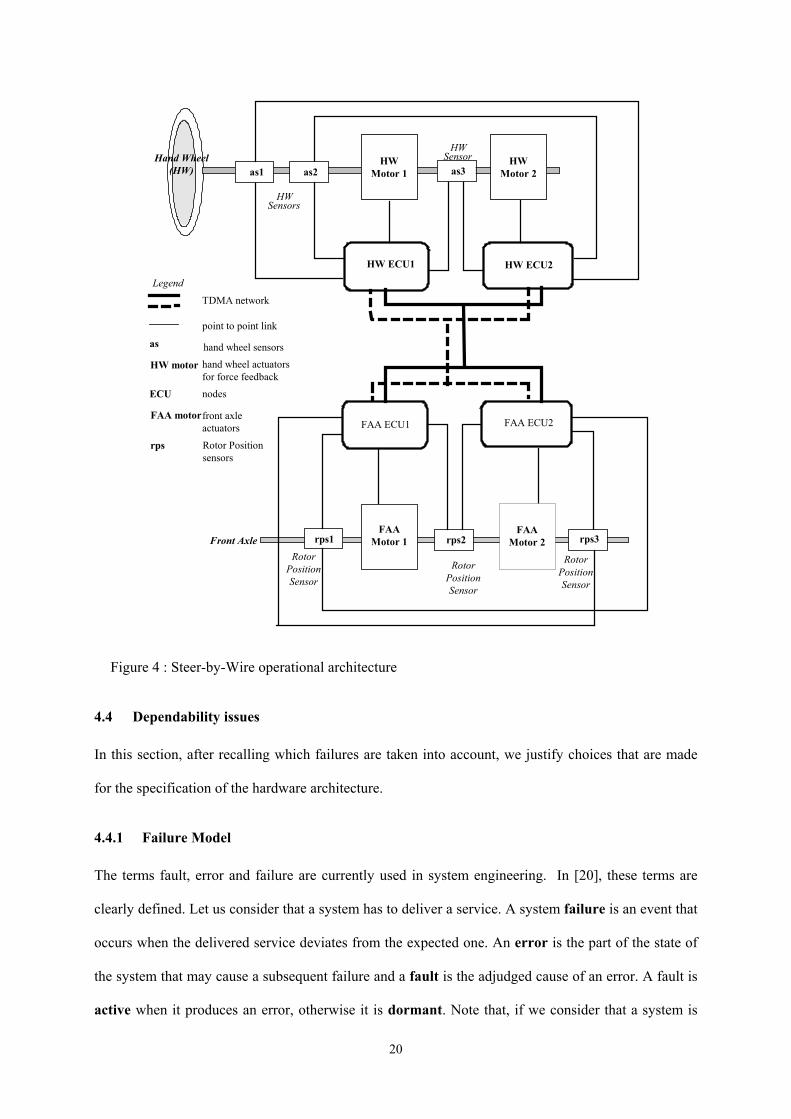
An operational architecture, which is a solution for the implementation of the functions presented in
section 4.1, is described in this section. Figure 4 illustrates the hardware architecture on which the
operational one is based. It includes four Electronic Control Units (micro-controllers) named,
respectively, HW ECU1 (Hand Wheel ECU1), HW ECU2 (Hand Wheel ECU2), FAA ECU1 (Front
Axle Actuator ECU1), and FAA ECU2 (Front Axle Actuator ECU2). Each node is connected to the
two TDMA-based communication channels (BUS1 and BUS2). Finally, three sensors, named as1, as2
and as3, placed near the hand wheel measure the requests of the driver in a similar way, the latter
being translated into a 3-tuple <hand wheel angle, hand wheel torque, hand wheel speed>. Three other
sensors, named rps1, rps2 and rps3, are dedicated to the measurement of the front axle position.
Finally, two motors (FAA Motor2 and FAA Motor2), configured in active redundancy, act on the front
axle while two other motors (HW Motor1 and HW Motor2) realize the force feedback control on the
18
hand wheel. Sensors as1, as2 and as3 (respectively, sensors rps1, rps2 and rps3) are connected by
point-to-point links, both to HW ECU1 and HW ECU2 (respectively, FAA ECU1 and FAA ECU2).
Implementation of the “Front axle control” function
The requests of the driver are measured by the three replicated sensors as1, as2 and as3 and sent to
both HW ECU1 and HW ECU2. Each ECU performs a majority vote on the 3 received values and
transmits a “secure” data on both communication channels BUS1 and BUS2. The two ECUs, FAA
ECU1 and FAA ECU2, placed behind the front axle, consume this data, as well as the last wheel
position, in order to elaborate the commands that are to be applied to FAA Motor 1 and 2.
Implementation of the “Force feedback control” function
In a way similar to the previous function, measurements taken by rps1, rps2 and rps3 are transmitted
both to FAA ECU1 and FAA ECU2. Each of these ECUs elaborates information transmitted on the
network. The consumers of this information are both HW ECU1 and HW ECU2 which compute the
command transmitted to HW Motor 1 and 2.
The replication of algorithms on several ECUs, of measurements from several similar sensors and of
information transmission over redundant buses is highly used in this operational architecture. The
choices made in terms of redundancy and diversification (see section 4.4.3) are constrained by
dependability, cost and dimension requirements. Alternative Steer-by-Wire architectures presented in
literature (e.g., [19]) use, in addition, two central ECUs located between the hand wheel and the front
but, from an economic point of view, it is of course preferable to use only four ECUs if dependability
criteria are met.
19
Hand Wheel(HW)
HW ECU1
rps1FAA
Motor 1
RotorPositionSensor
HW ECU2
FAA ECU1 FAA ECU2
HWMotor 1
HWSensors
HWMotor 2
rps3rps2
as1 as2 as3
Front Axle
Legend
TDMA network
point to point link
as
HW motor hand wheel actuatorsfor force feedback
ECU nodes
FAA motorfront axleactuators
rps Rotor Positionsensors
HWSensor
hand wheel sensors
RotorPositionSensor
RotorPositionSensor
FAAMotor 2
Figure 4 : Steer-by-Wire operational architecture
4.4 Dependability issues
In this section, after recalling which failures are taken into account, we justify choices that are made
for the specification of the hardware architecture.
4.4.1 Failure Model
The terms fault, error and failure are currently used in system engineering. In [20], these terms are
clearly defined. Let us consider that a system has to deliver a service. A system failure is an event that
occurs when the delivered service deviates from the expected one. An error is the part of the state of
the system that may cause a subsequent failure and a fault is the adjudged cause of an error. A fault is
active when it produces an error, otherwise it is dormant. Note that, if we consider that a system is
20
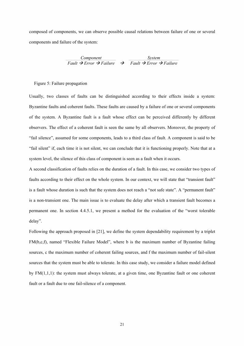
composed of components, we can observe possible causal relations between failure of one or several
components and failure of the system:
Component SystemFault Error Failure Fault Error Failure
Figure 5: Failure propagation
Usually, two classes of faults can be distinguished according to their effects inside a system:
Byzantine faults and coherent faults. These faults are caused by a failure of one or several components
of the system. A Byzantine fault is a fault whose effect can be perceived differently by different
observers. The effect of a coherent fault is seen the same by all observers. Moreover, the property of
“fail silence”, assumed for some components, leads to a third class of fault. A component is said to be
“fail silent” if, each time it is not silent, we can conclude that it is functioning properly. Note that at a
system level, the silence of this class of component is seen as a fault when it occurs.
A second classification of faults relies on the duration of a fault. In this case, we consider two types of
faults according to their effect on the whole system. In our context, we will state that “transient fault”
is a fault whose duration is such that the system does not reach a “not safe state”. A “permanent fault”
is a non-transient one. The main issue is to evaluate the delay after which a transient fault becomes a
permanent one. In section 4.4.5.1, we present a method for the evaluation of the “worst tolerable
delay”.
Following the approach proposed in [21], we define the system dependability requirement by a triplet
FM(b,c,f), named “Flexible Failure Model”, where b is the maximum number of Byzantine failing
sources, c the maximum number of coherent failing sources, and f the maximum number of fail-silent
sources that the system must be able to tolerate. In this case study, we consider a failure model defined
by FM(1,1,1): the system must always tolerate, at a given time, one Byzantine fault or one coherent
fault or a fault due to one fail-silence of a component.
21
4.4.2 Operational architecture vs dependability requirements
In this section, we give some rules that we applied for designing the architecture. The system under
study has to provide two main services: controlling the front axle according to the driver requests and
furnishing a force feedback to the driver. We focus on the former. A similar rationale can be used for
the second one. In both cases, the main question is the evaluation of the minimum number of
redundant components that contribute to meet the dependability requirement.
Dependability analyses are generally based on a strong hypothesis assuming that, in the whole system,
n simultaneous component failures can never occur for any set of redundant components (set of
redundant hand wheel sensors, set of redundant “Hand Wheel ECU”, …). In this case study, we
suppose that n is equal to 1.
Note that in [22], Lamport states that 3n+1 redundant components are necessary to tolerate n
Byzantine faults. In order to tolerate n coherent faults, it is sufficient to have 2n+1 redundant
components.
ECU redundancy
Two functions need to be implemented in ECU: Front Axle Control and Force Feedback Control. To
avoid costly and numerous wires, ECUs have to be placed close to the sensors, and communication
between ECUs has to be multiplexed. A Hand Wheel ECU (respectively, a Front Axle ECU) is a
consumer of information sampled from the hand wheel (respectively, front axle) and is a producer of
information used by the Front Axle Control function (respectively, Force Feedback Control function)
implemented in a Front Axle ECU (respectively, in a Hand Wheel ECU). According to the rule given
by Lamport, the minimum number of redundant Hand Wheel ECUs (respectively, Front Axle ECUs)
should be 4. This solution is mainly used in the aeronautic domain. But, automotive requirements are
completely different in terms of cost and space. Therefore a classical solution is to use Fail-Silent
ECUs. In this case, obviously, only two Hand Wheel ECUs (respectively, Front Axle ECUs) are
necessary. However, we have to ensure the fail-silence property. To do this, several techniques based
on the Petri-Nets analysis [23], C Model simulation [24] or fault injection [25] are used.
22
Hand Wheel Sensor redundancy
A Hand Wheel sensor produces information for two Hand Wheel ECUs. Three Hand Wheel sensors
are necessary for ensuring that each Hand Wheel ECU, assumed to provide a voting algorithm, is able
to tolerate one Byzantine fault (and subsequently one coherent fault or one fail-silent sensor).
Actuator Redundancy
Actuators are mechanical components without any calculating ability, and a single actuator can take
charge of piloting the Front Axle. Furthermore, according to the inherent reliability properties of these
actuators, we guarantee that an actuator can never wrongly apply an order received by a Front Axle
ECU. Under these assumptions and taking into account the formerly stated fail-silence property of a
Front Axle ECU, only 2 couples <Front Axle ECU,actuator> are necessary for the tolerance of, at
most, one fault.
4.4.3 Redundancy and diversification
According to the dependability requirements, presented in section 4.2, and to the assumption made on
the ECUs (fail-silence in our case) and according to the failure occurrence model (section 4.4.1), a
certain level of redundancy has to be implemented. If the chosen fault-tolerance strategy is failure
recovery, redundant ECUs will work only in the case of the primary ECU failing. In this case, failure
detection must be quick and reliable. Otherwise, if the strategy is failure compensation, as with the
front axle motors, redundant ECUs will be placed in parallel and work simultaneously. Because of the
stringent real-time constraint, our architecture must provide failure compensation.
It is worthy to note that the redundancy of identical ECUs does not prevent the architecture from
common mode failures: the hardware of redundant ECUs should be furnished by different suppliers
and their software realized by different teams. The Ariane 501 explosion is a good example to show
the importance of diversification. Both back-up and active inertial reference systems failed for the
same reason [26]. If software and/or hardware had been diversified, one of the two inertial reference
systems would have remained safe. But, for cost and maintenance reasons, it is not always possible to
implement diversified components and technologies.
23
4.4.4 Configuration of the communication protocol
Communication is driven by a TDMA-based protocol with two replicated channels. More precisely,
the network that is used in this case study is TTP/C because of the availability of the protocol
specification and the components. However, the same analysis is valid for any time-triggered protocol
such as TTCAN and FlexRay.
For reliability reasons, the same frame is transmitted on the two replicated channels. In order to avoid
common mode failures (EMI, temperature, …) channels should be placed as far as possible from each
other in the vehicle.
4.4.4.1 Slot allocation strategy to maximize the “robustness” of the transmission
In TTP/C, the transmission order inside a round can be freely chosen by the application designer.
Among the criteria for constructing the TDMA round, applicative constraints like computation time
and sampling rates can be taken into account. But, as shown in [27, 28], the robustness of a TDMA-
based system against transmission errors heavily depends on the location of the slots inside the round.
In automotive systems, one observes that transmission errors are highly correlated: there occur
perturbations that corrupt several consecutive frames (so called "bursts" of errors). Should two frames
that belong to the same FTU (Fault Tolerant Unit, see section 3.1.2) be transmitted just one after the
other, then a single perturbation could corrupt both of the frames. The objective to pursue depends on
the status of the FTU with regard to the concept of “fail-silence” (see 3.1.3). For FTUs composed of a
set of fail-silent nodes, the successful transmission of one single frame for the whole set of replicas is
sufficient since the value carried by the frame is necessarily correct. In this case, the objective to
achieve with regard to the robustness against transmission errors is the minimizing of the probability
that all frames of the FTU (carrying data corresponding to the same production cycle) be corrupted.
This probability is denoted P_all in [27].
In practice, replicated sensors may return slightly different observations and, without extra
communication for an agreement, replicated nodes of a same FTU may transmit different data. If a
decision, such as a majority vote, has to be taken by a node with regard to the value of the transmitted
data, the objective is to maximize probability that at least one frame of each FTU is successfully
24
transmitted during a production cycle. If the production cycle is equal to one round then it comes back
to minimizing P_one, the probability that one or more frames of an FTU have become corrupted.
It has been shown in [27], with some reasonable assumptions on the error model, that the optimal
solution to minimize P_all is to “spread” the different frames of a same FTU uniformly over the
TDMA round. An algorithm that ensures the optimal solution is provided for the case where the FTUs
have, at most, two different cardinalities (for instance, one FTU is made of 2 replicas and other FTUs
are made of 3 replicas). For the other cases, a low-complexity heuristic is proposed [27], and it was
proven to be close to the optimal on simulations that were performed.
In [28], it was demonstrated that, under very weak assumptions on the error model and whatever the
number of FTUs and their cardinalities, the clustering together of the transmission of all the frames of
an FTU minimizes P_one when the production cycle of the data sent is equal to the length of a TDMA
round.
These two results, for the fail-silent case and non fail-silent case, provide simple guidelines to the
application designer for designing the schedule of transmission. In our case-study, since all ECUs are
fail-silent, our requirement is to minimize the probability of losing all replicas in the TDMA round,
and thus the redundant frames have to be spread over time.
4.4.4.2 Allocation of the slots in the round
Let us consider the architecture shown in Figure 4 with the following characteristics for the production
of data:
HW ECU1/ HW ECU2 - production of two pieces of data packed in a single frame:
- HW Angle every 2ms,
- HW Torque every 4ms.
FAA ECU1/ FAA ECU2 - production of two pieces of data packed in a single frame:
- FAA position every 2ms,
- Tie Rod Force every 4ms.
The size of the TDMA Round is set to the minimal production period, i.e., 2ms. Since the frames are
composed of the same information, whatever the round, the size of the cluster cycle is equal to one
25
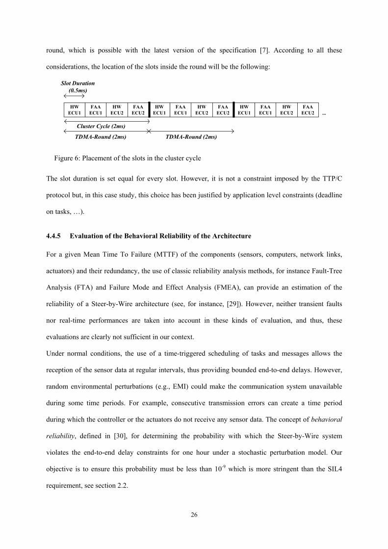
round, which is possible with the latest version of the specification [7]. According to all these
considerations, the location of the slots inside the round will be the following:
HWECU1
HWECU2
FAAECU2
Cluster Cycle (2ms)
HWECU1
FAAECU1
HWECU2
FAAECU2
FAAECU1
TDMA-Round (2ms) TDMA-Round (2ms)
Slot Duration(0.5ms)
...HW
ECU2FAA
ECU2HW
ECU1FAA
ECU1
Figure 6: Placement of the slots in the cluster cycle
The slot duration is set equal for every slot. However, it is not a constraint imposed by the TTP/C
protocol but, in this case study, this choice has been justified by application level constraints (deadline
on tasks, …).
4.4.5 Evaluation of the Behavioral Reliability of the Architecture
For a given Mean Time To Failure (MTTF) of the components (sensors, computers, network links,
actuators) and their redundancy, the use of classic reliability analysis methods, for instance Fault-Tree
Analysis (FTA) and Failure Mode and Effect Analysis (FMEA), can provide an estimation of the
reliability of a Steer-by-Wire architecture (see, for instance, [29]). However, neither transient faults
nor real-time performances are taken into account in these kinds of evaluation, and thus, these
evaluations are clearly not sufficient in our context.
Under normal conditions, the use of a time-triggered scheduling of tasks and messages allows the
reception of the sensor data at regular intervals, thus providing bounded end-to-end delays. However,
random environmental perturbations (e.g., EMI) could make the communication system unavailable
during some time periods. For example, consecutive transmission errors can create a time period
during which the controller or the actuators do not receive any sensor data. The concept of behavioral
reliability, defined in [30], for determining the probability with which the Steer-by-Wire system
violates the end-to-end delay constraints for one hour under a stochastic perturbation model. Our
objective is to ensure this probability must be less than 10-9 which is more stringent than the SIL4
requirement, see section 2.2.
26
The end-to-end delay for the front axle control function is composed of the so-called “pure delay”
(delay induced by the system before the driver’s command is given to the actuators) and the
mechatronic delay introduced by the actuators (electric motors in our case). The mechatronic delay can
be bounded by a constant Tmec. In what follows, we will only focus on the analysis of the pure delay
analysis which is denoted by Tp. Systems that are not able to ensure a pure delay Tp lower than a
tolerable upper bound Tmax are considered to be unstable. The value of Tmax can be estimated by tests in
vehicles and simulations.
The behavioral reliability is estimated by the probability that the pure delay is greater than the
maximum tolerable bound : PBR = P[Tp > Tmax]. When Tp is equal to or lower than Tmax, the quality of
service is degraded while the vehicle is considered to be potentially unstable when Tp > Tmax .
4.4.5.1 Evaluation of Tmax
To illustrate the method, only the function “turning the wheels according to driver’s request” is
considered. The evaluation of Tmax can be performed either by testing in a vehicle or by using
Matlab/Simulink. The method we adopted was using Matlab/Simulink first, and confirming the results
with testing in vehicles. The software framework used was composed of a Matlab/Simulink model of
the Steer-by-Wire architecture and a vehicle environment model.
The architecture presented in section 4.3 was simulated according to a hand wheel angle utilization
profile (positions of the hand wheel over time). The impact of the variation of Tp on performance,
mainly the stability of the vehicle and the time needed to reach the requested wheel angle, was
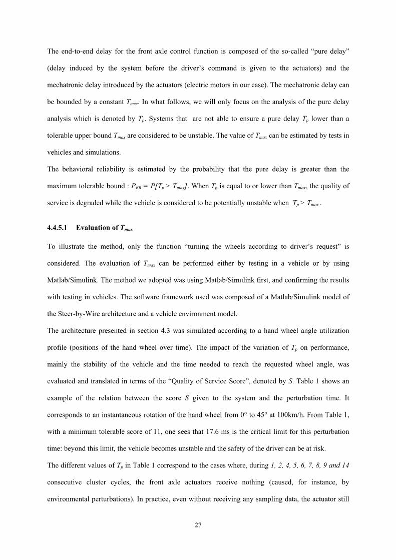
evaluated and translated in terms of the “Quality of Service Score”, denoted by S. Table 1 shows an
example of the relation between the score S given to the system and the perturbation time. It
corresponds to an instantaneous rotation of the hand wheel from 0° to 45° at 100km/h. From Table 1,
with a minimum tolerable score of 11, one sees that 17.6 ms is the critical limit for this perturbation
time: beyond this limit, the vehicle becomes unstable and the safety of the driver can be at risk.
The different values of Tp in Table 1 correspond to the cases where, during 1, 2, 4, 5, 6, 7, 8, 9 and 14
consecutive cluster cycles, the front axle actuators receive nothing (caused, for instance, by
environmental perturbations). In practice, even without receiving any sampling data, the actuator still
27
performs but the turning of the front axle is made, for instance, on the basis of the command of the
previous period, or with an estimation based on the commands of several previous periods. So, in this
case Tp + Tmec is no longer the end-to-end delay strictly speaking, but the delay during which the
system has not been able to take into account the current hand wheel angle in order to compute the
commands for the actuators.
Configuration of the Steering System
TP (ms) Score S
Mechanical steering system
0 11.23
Steer-by-Wire 3.6 11.21 Steer-by-Wire 5.6 11.19 Steer-by-Wire 9.6 11.15 Steer-by-Wire 11.6 11.13 Steer-by-Wire 13.6 11.10 Steer-by-Wire 15.6 11.05 Steer-by-Wire 17.6 11 Steer-by-Wire 19.6 10.90 Steer-by-Wire 29.6 10.45
Table 1: QoS score vs. perturbation time
4.4.5.2 Quantification of the Behavioral Reliability
With the use of the TTP/C network, communication cycles are predefined and cyclic. However, as will
be shown by the analysis of the example shown in Figure , Tp can be greater than a cluster cycle
because of a possible desynchronization between the sampling period and the cluster cycle. The
evaluation of the behavioral reliability should be based on the worst case Tp but not the nominal Tp
because of the safety-critical nature of the system. Moreover, with transient failures due to
perturbations, Tp becomes a random variable. Therefore, in this section, we first evaluate Tp and then
the behavioral reliability.
Worst case pure delay without transient failures
28
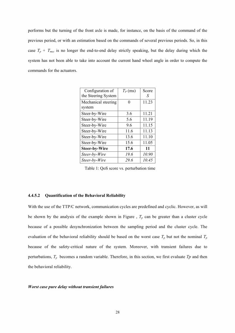
Figure shows the temporal characteristics of the front axle control function and the relationship with
the cluster cycles. The Fault Tolerant Communication Layer (section 3.3.2) has been configured so
that the front axle ECUs (FAA ECU1 and 2) have to wait for all replicas of data before consuming
them.
t
HWAECU1
FAAECU1
HWAECU2
FAAECU2
HWAECU1
FAAECU1
HWAECU2
FAAECU2
...
cluster cycle (T )MA
hand wheelsampling i
hand wheelsampling i+1
sensors
HW ECU1HW ECU2
treatement of samplenumber i
end oftransmissionof data i-1
end oftransmissionof data i
datai-1
data i+1data iBuffers of
HW ECU1
HW ECU2
treatement of samplenumber i+1
data i-1 data i+1 data i
transmission ofdata i-1
transmission ofdata i
TDMA cycle
treatement ofdata i-1
treatement ofdata i
FAA ECUs
actuator actionfor data i-1
Actuators
actuator actionfor data i
TNET TT
Pure delay for data iMechatronic
delay
t i t i-1
Figure 7: Temporal characteristics of the function “turning the wheels according to the driver’s
request”
Cluster cycles are numbered by index i = 1, 2, … The ith cluster cycle starts at ti. For the front axle
control function, the “worst case pure delay”, denoted by TpWC, appears when the ith hand wheel sensor
sampling period starts just after ti. This slight desynchronization leads to a situation where, during the
ith cluster cycle, only the data elaborated using the sample of the (i-1)th cluster cycle are transmitted to
the front axle ECUs. In fact, in TTP/C, data kept in the buffer of each HW ECU is transmitted at the
beginning of each slot. In Figure , at the beginning of each HWA ECU slot, data in the buffer has not
29
yet been refreshed and only data corresponding to the previous sample is transmitted. So, the worst
case delay between the ith HWA sample and the beginning of the ith actuation is given by:
WCp MA NET TT T T= + +T (1)
where TMA is the duration of a cluster cycle, TNET corresponds to the delay between the beginning of a
cluster cycle and the arrival of all the replicas to the FAA ECU2, and where TT is the treatment time
of the data within a FAA ECU.
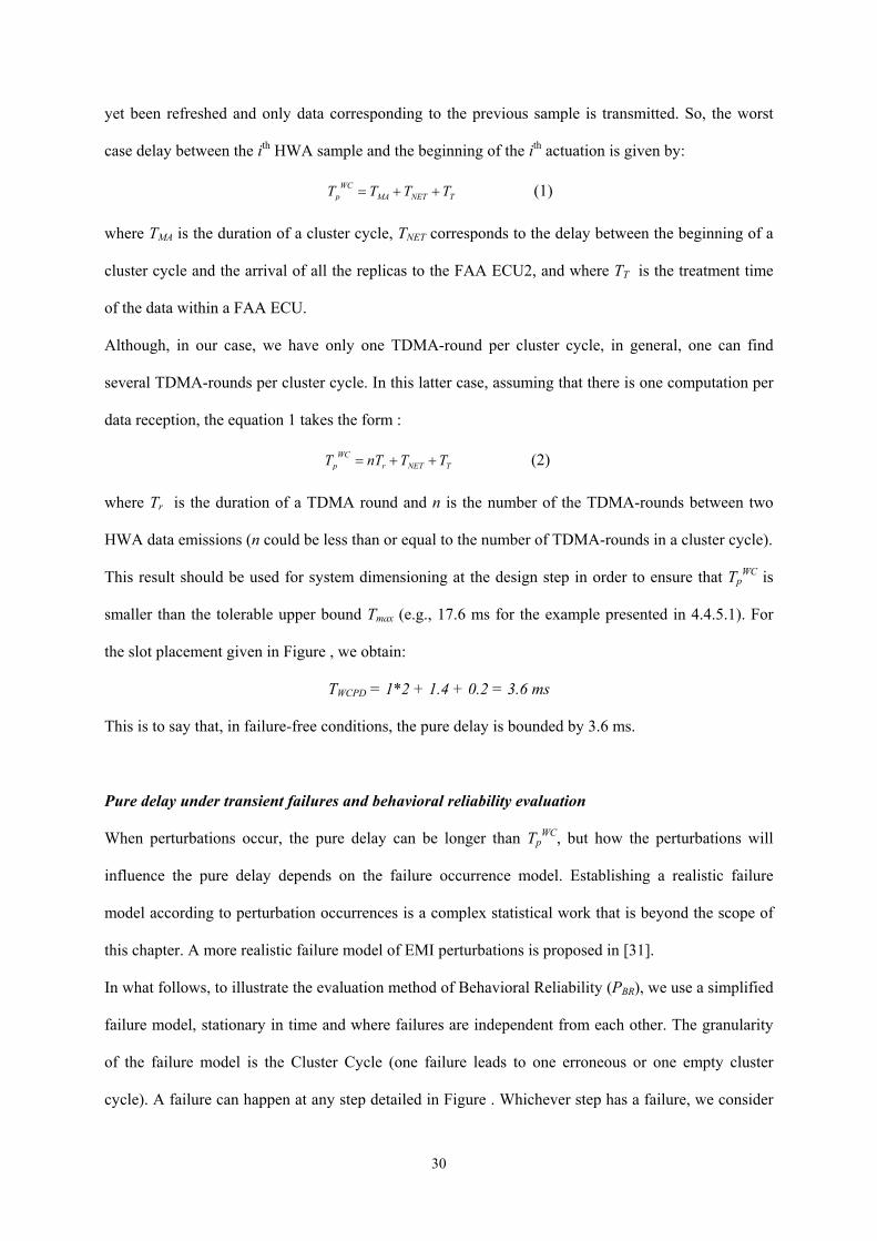
Although, in our case, we have only one TDMA-round per cluster cycle, in general, one can find
several TDMA-rounds per cluster cycle. In this latter case, assuming that there is one computation per
data reception, the equation 1 takes the form :
WCp r NETT nT T= + + TT (2)
where Tr is the duration of a TDMA round and n is the number of the TDMA-rounds between two
HWA data emissions (n could be less than or equal to the number of TDMA-rounds in a cluster cycle).
This result should be used for system dimensioning at the design step in order to ensure that TpWC is
smaller than the tolerable upper bound Tmax (e.g., 17.6 ms for the example presented in 4.4.5.1). For
the slot placement given in Figure , we obtain:
TWCPD = 1*2 + 1.4 + 0.2 = 3.6 ms
This is to say that, in failure-free conditions, the pure delay is bounded by 3.6 ms.
Pure delay under transient failures and behavioral reliability evaluation
When perturbations occur, the pure delay can be longer than TpWC, but how the perturbations will
influence the pure delay depends on the failure occurrence model. Establishing a realistic failure
model according to perturbation occurrences is a complex statistical work that is beyond the scope of
this chapter. A more realistic failure model of EMI perturbations is proposed in [31].
In what follows, to illustrate the evaluation method of Behavioral Reliability (PBR), we use a simplified
failure model, stationary in time and where failures are independent from each other. The granularity
of the failure model is the Cluster Cycle (one failure leads to one erroneous or one empty cluster
cycle). A failure can happen at any step detailed in Figure . Whichever step has a failure, we consider
30
that no information is transmitted to the actuators during this cluster cycle (the information is lost or
destroyed before the command is given to the actuators). In the worst case, each time a failure occurs,
the actuator has to wait TpWC plus one cluster cycle TMA to receive refreshed information. Let Tp
WC,ERR
denotes the maximum delay with N consecutive erroneous cluster cycles:
p
]
,WC ERR WC WCp MA p rT NT T NnT T= + = + (3)
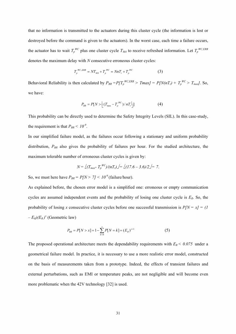
Behavioral Reliability is then calculated by PBR =P[TpWC,ERR > Tmax] = P[N(nTr) + Tp
WC > Tmax]. So,
we have:
max[ ( ) /WCBR p rP P N T T nT = > − (4)
This probability can be directly used to determine the Safety Integrity Levels (SIL). In this case-study,
the requirement is that PBR < 10-9.
In our simplified failure model, as the failures occur following a stationary and uniform probability
distribution, PBR also gives the probability of failures per hour. For the studied architecture, the
maximum tolerable number of erroneous cluster cycles is given by:
N = (Tmax- TpWC)/(nTr) = (17.6 – 3.6)/2 = 7.
So, we must here have PBR = P[N > 7] < 10-9 (failure/hour).
As explained before, the chosen error model is a simplified one: erroneous or empty communication
cycles are assumed independent events and the probability of losing one cluster cycle is ER. So, the
probability of losing x consecutive cluster cycles before one successful transmission is P[N = x] = (1
– ER)(ER )x (Geometric law)
1
0
[ ] 1 [ ] ( )x
xBR R
k
P P N x P N k E +
=
= > = − = =∑ (5)
The proposed operational architecture meets the dependability requirements with ER < 0.075 under a
geometrical failure model. In practice, it is necessary to use a more realistic error model, constructed
on the basis of measurements taken from a prototype. Indeed, the effects of transient failures and
external perturbations, such as EMI or temperature peaks, are not negligible and will become even
more problematic when the 42V technology [32] is used.
31
5 Conclusion
X-by-Wire is a clear trend of automotive development due to the advantages of the electronic
components for enhancing safety, functionality and reducing cost.
In this chapter, after having examined the real-time and dependability constraints of the X-by-Wire
systems, we reviewed the fault-tolerant services and the communication protocols (TTP/C, FlexRay
and TTCAN) that are needed for such systems. Methods for designing a dependable X-by-Wire
system were described and a Steer-by-Wire system based on TTP/C was then used as a case study. We
showed how to build a fault-tolerant architecture by choosing the necessary redundant components
and the schedule of transmission. A method for evaluating the probability that the real-time constraints
would be violated under a simple perturbation model was also proposed. This method can be used to
predict whether the architecture meets the SIL4 requirement.
If the dependability of the X-by-Wire can be evaluated by assuming that one can establish a realistic
failure model, the certification organization still remains to be convinced. At the time of writing, the
legislation in some countries does not authorize fully X-by-Wire cars to circulate. The use of X-by-
Wire systems mass production cars in the future also depends on other factors such as the advances in
the 42V technology.
References
1 Society of Automotive Engineers (SAE) public discussion: 42 Volt Electrical Systems et Fuel Cells :
Harmonious marriage or incompatible partners ?, SAE (N.Traub), General Motors (Ch.Borroni-Bird,
Director of Design and Technology Fusion), Delphi (J.Botti, Innovation Center), Daimler Chrysler
(T.Moore, Vice President, Liberty and Technical Affairs), UTC Fuels Cells (F.R.Preli, Vice President,
Engineering), SAE 2003 World Congress & Exhibition, Detroit (USA), 2003.
2 IEC61508-1, Functional Safety of Electrical Electronic Programmable Electronic Safety-related Systems -
Part 1 : General requirements, IEC/SC65A, 1998.
3 J. Rushby, A Comparison of Bus Architectures for Safety-Critical Embedded Systems, Technical report,
Computer Science Laboratory SRI International, 2003.
32
4 E. Dilger, T. Führer, B. Müller, S. Poledna, The X-By-Wire Concept: Time-Triggered Information
Exchange and Fail Silence Support by new System Services, Technische Universität Wien, Institut für
Technische Informatik, n°7/1998, also available as SAE Technical Paper 98055, 1998.
5 C. Temple, Avoiding the Babbling-Idiot Failure in a Time-Triggered Communication System, International
Symposium on Fault-Tolerant Computing (FTCS), Munich (Germany), 1998.
6 S. Poledna, P. Barrett, A. Burns, A. Wellings, Replica Determinism and Flexible Scheduling in Hard Real-
Time Dependable Systems, IEEE Transactions on Computers, vol.49, n°2, pp100-111, 2000.
7 Time-Triggered Protocol TTP/C, High-Level Specification Document, Protocol Version 1.1, 2003.
8 H. Kopetz, Real-Time Sytems: Design Principles for Distributed Embedded Applications, Kluwer Academic
Publishers, 1997.
9 H. Pfeifer, Formal Verification of the TTP Group Membership Algorithm, FORTE/PSTV Euroconference,
Pisa (Italy), 2000.
10 H. Kopetz, R. Nossal, R. Hexel, A Krüger, D. Millinger, R.Pallierer, C. Temple, M. Krug, Mode Handling
in the Time-Triggered Architecture, Control Engineering Practice, vol.6, pp61-66, 1998.
11 TTTech Computertechnik AG, http://www.tttech.com/, 2004.
12 G. Bauer, M. Paulitsch, An Investigation of Membership and Clique Avoidance in TTP/C, 19th IEEE
Symposium on Reliable Distributed Systems, Nuremberg (Germany), 2000.
13 FlexRay Consortium, http://www.flexray.com, 2004.
14 Road vehicles – Controller area network (CAN) – Part 4 : Time Triggered Communication - ISO 11898-4.
15 Bosch – Time Triggered Communication on CAN, http://www.can.bosch.com/content/TT_CAN.html, 2004.
16 OSEK Consortium, OSEK/VDX Time-Triggered Operating System, Version 1.0, available at
http://www.osek-vdx.org/, 2001.
17 OSEK Consortium, OSEK/VDX Fault-Tolerant Communication, Version 1.0, available at http://www.osek-
vdx.org/, 2001.
18 N. Tracey, Comparing OSEK and OSEKTime, Embedded System Conference (ESC) Europe, Stuttgart,
2001.
19 X-by-Wire Project, Brite-EuRam 111 Program, X-By-Wire - Safety Related Fault Tolerant Systems in
Vehicles, Final Report, 1998.
33
20 A. Avizienis, J.-C. Laprie and B. Randell, “Fundamental Concepts of Dependability”, in 3rd Information
Survivability Workshop, (Boston, MA, USA), pp 7-12, IEEE Computer Society Press, 2000.
21 J. A. Garay, K. J. Perry, A Continuum of Failure Models for Distributed Computing, 6th Distributed
Algorithm International Workshop (WDAG), Haifa (Israel), 1992.
22 L. Lamport, R. Shostak, M. Pease, The Byzantine Generals Problem , ACM Transactions on Programming
Language and Systems, vol. 4, no. 3, pp382-401, 1982.
23 G. Grünsteidl, H. Kantz, H. Kopetz, Communication Reliability in Distributed Real-Time systems, 10th
IFAC Workshop on Distributed Computer Control Systems, Semmering (Austria), 1991.
24 P. Herout,S, Racek, J. Hlavicka, Model-based Dependability Evaluation Method for TTP/C Based Systems,
EDCC-4 - Fourth European Dependable Computing Conference, Toulouse (France), 2002.
25 R. Hexel, FITS: a Fault Injection Architecture for Time-Triggered Systems, 26th Australian Computer
Science Conference (ACSC2003), Adelaide (Australia), 2003.
26 Report by the Inquiry Board, Ariane 501 Flight Failure,
http://www.mssl.ucl.ac.uk/www_plasma/missions/cluster/about_cluster/cluster1/ariane5rep.html, 1996.
27 B. Gaujal, N. Navet, Maximizing the Robustness of TDMA Networks with Application to TTP/C, Technical
Report RR-4614, INRIA, 2002.
28 B. Gaujal, N. Navet, Optimal Replica Allocation for TTP/C BasedSystems, 5th FeT IFAC Conference
(FeT'2003), Aveiro (Portugal), July 2003.
29 R. Hammett, P. Babcock, Achieving 10-9 Dependability With Drive-By-Wire Systems, SAE 2003 World
Congress & Exhibition, Detroit (USA), 2003.
30 C. Wilwert, Y.Q. Song, F. Simonot-Lion, T. Clément, Evaluating Quality of Service and Behavioral
Reliability of Steer-by-Wire systems, 9th IEEE International Conference on Emerging Technologies and
Factory Automation (ETFA), Lisbon (Portugal), 2003.
31 N. Navet, Y.Q. Song, F. Simonot, Worst-case Deadline Failure Probability in Real-Time Applications
Distributed over CAN (Controller Area Network), Journal of Systems Architecture, vol. 46, pp607-617,
2000.
32 H. Kopetz, H. Kantz, G. Gründsteidl, P. Puschner, J. Reisinger, Tolerating Transient Fault in MARS, 20th
Symposium of Fault Tolerant Computing, Newcaste upon Tyne, UK, 1990.
34


![Automotive Engineering - July 2015 [26 - 27]briengineering.com/.../2015/08/Automotive-Engineering-July-2015.pdf · AUTOnomy and Hy-wire, unveiled by GM in 2001 and 2002, ... details](https://img.pdfslide.net/doc/110x75/5aa9ceb57f8b9a86188d4a01/automotive-engineering-july-2015-26-27-and-hy-wire-unveiled-by-gm-in-2001.jpg)