Embed Size (px)
Citation preview
8/2/2019 Design of Bearing Stiffeners in Cold Formed C-Sections
http://slidepdf.com/reader/full/design-of-bearing-stiffeners-in-cold-formed-c-sections 1/151
Design of BearingStiffeners in Cold Formed
Steel C-Sections
R E S E A R C H R E P O R T R P 0 1 - 1
J U L Y 2 0 0 1
R E V I S I O N 2 0 0 6
research repor
American Iron and Steel Institute
Committee on Specifications
for the Design of Cold-Formed
Steel Structural Members
8/2/2019 Design of Bearing Stiffeners in Cold Formed C-Sections
http://slidepdf.com/reader/full/design-of-bearing-stiffeners-in-cold-formed-c-sections 2/151
The material contained herein has been developed by researchers based on their researchfindings. The material has also been reviewed by the American Iron and Steel InstituteCommittee on Specifications for the Design of Cold-Formed Steel Structural Members. TheCommittee acknowledges and is grateful for the contributions of such researchers.
The material herein is for general information only. The information in it should not be
used without first securing competent advice with respect to its suitability for any givenapplication. The publication of the information is not intended as a representation or warrantyon the part of the American Iron and Steel Institute, or of any other person named herein, thatthe information is suitable for any general or particular use or of freedom from infringement ofany patent or patents. Anyone making use of the information assumes all liability arising fromsuch use.
Copyright 2001 American Iron and Steel Institute
Revised Edition Copyright 2006 American Iron and Steel Institute
8/2/2019 Design of Bearing Stiffeners in Cold Formed C-Sections
http://slidepdf.com/reader/full/design-of-bearing-stiffeners-in-cold-formed-c-sections 3/151
Design of Bearing Stiffeners in Cold
Formed Steel C-Sections
by
Steven R. Fox
Research Assistant
Prof. Reinhold M. Schuster
Project Director
A Research Project Sponsored by:
American Iron and Steel Institute
Canadian Sheet Steel Building Institute
July 2001
Canadian Cold Formed Steel Research Group
University of Waterloo, Canada
8/2/2019 Design of Bearing Stiffeners in Cold Formed C-Sections
http://slidepdf.com/reader/full/design-of-bearing-stiffeners-in-cold-formed-c-sections 4/151
i
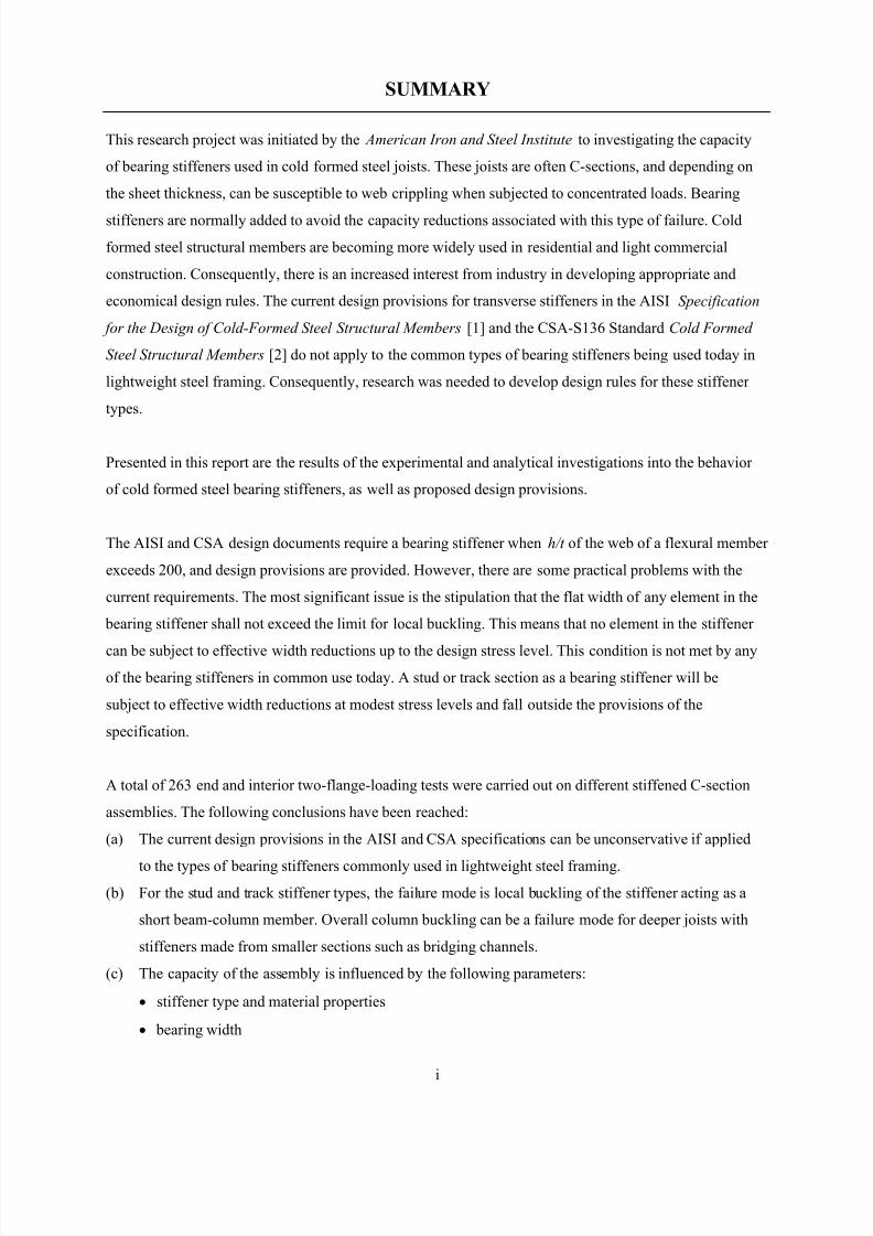
SUMMARY
This research project was initiated by the American Iron and Steel Institute to investigating the capacity
of bearing stiffeners used in cold formed steel joists. These joists are often C-sections, and depending on
the sheet thickness, can be susceptible to web crippling when subjected to concentrated loads. Bearing
stiffeners are normally added to avoid the capacity reductions associated with this type of failure. Cold
formed steel structural members are becoming more widely used in residential and light commercial
construction. Consequently, there is an increased interest from industry in developing appropriate and
economical design rules. The current design provisions for transverse stiffeners in the AISI Specification
for the Design of Cold-Formed Steel Structural Members [1] and the CSA-S136 Standard Cold Formed
Steel Structural Members [2] do not apply to the common types of bearing stiffeners being used today in
lightweight steel framing. Consequently, research was needed to develop design rules for these stiffener
types.
Presented in this report are the results of the experimental and analytical investigations into the behavior
of cold formed steel bearing stiffeners, as well as proposed design provisions.
The AISI and CSA design documents require a bearing stiffener when h/t of the web of a flexural member
exceeds 200, and design provisions are provided. However, there are some practical problems with the
current requirements. The most significant issue is the stipulation that the flat width of any element in the
bearing stiffener shall not exceed the limit for local buckling. This means that no element in the stiffener
can be subject to effective width reductions up to the design stress level. This condition is not met by any
of the bearing stiffeners in common use today. A stud or track section as a bearing stiffener will be
subject to effective width reductions at modest stress levels and fall outside the provisions of the
specification.
A total of 263 end and interior two-flange-loading tests were carried out on different stiffened C-section
assemblies. The following conclusions have been reached:
(a) The current design provisions in the AISI and CSA specifications can be unconservative if applied
to the types of bearing stiffeners commonly used in lightweight steel framing.
(b) For the stud and track stiffener types, the failure mode is local buckling of the stiffener acting as a
short beam-column member. Overall column buckling can be a failure mode for deeper joists with
stiffeners made from smaller sections such as bridging channels.
(c) The capacity of the assembly is influenced by the following parameters:
• stiffener type and material properties
• bearing width
8/2/2019 Design of Bearing Stiffeners in Cold Formed C-Sections
http://slidepdf.com/reader/full/design-of-bearing-stiffeners-in-cold-formed-c-sections 5/151
ii
• joist size and material properties
• number and pattern of fasteners connecting the stiffener to the joist
• location of the stiffener on the joist (i.e. end or intermediate, inside or outside)
• gap between the stiffener and the joist flanges
(d) The capacity of the stiffened joist assembly is a combination of the web crippling capacity of the
joist plus the axial capacity of the stiffener, times a reduction factor.
(e) The web crippling capacity of the joist is influenced by the presence of the bearing stiffener and the
connection of the stiffener to the joist web. Web crippling of the joist should be considered as the
serviceability limit sate for the assembly.
(f) The design of the stiffener must take into account the eccentric axial loads and lateral loads
transferred from the fasteners.
(g) This project has only considered the stiffener and joist assembly. No recognition was made of the
other components also commonly present in a floor (e.g. rim joist, sub-floor) that add to the strength
of the assembly.
(h) A simplified design approach is proposed for those stiffeners not subject to column-type buckling.
This project was supported financially by both the American Iron and Steel Institute and the Canadian
Sheet Steel Building Institute.
8/2/2019 Design of Bearing Stiffeners in Cold Formed C-Sections
http://slidepdf.com/reader/full/design-of-bearing-stiffeners-in-cold-formed-c-sections 6/151
iii
TABLE OF CONTENTS
Summary........................................................................................................................................................i
Table of Contents.........................................................................................................................................iii
List of Figures.............................................................................................................................................vii
Lst of Tables ................................................................................................................................................. x
1 Background.......................................................................................................................................... 1
1.1 Growing Applications of Cold Formed Steel in Residential Construction................................... 1
1.2 Research Objective and Scope...................................................................................................... 3
2 Earlier Work......................................................................................................................................... 5
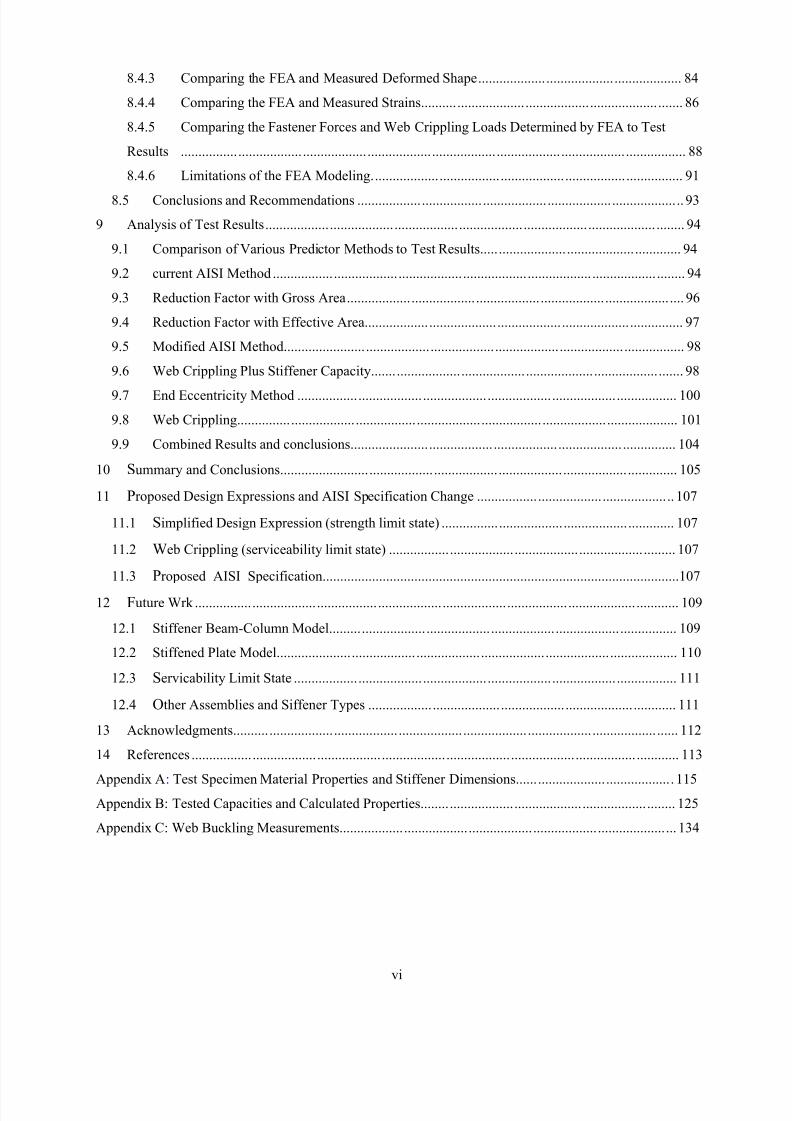
2.1 Nguyen & Yu, 1978...................................................................................................................... 5
2.1.1 Background...........................................................................................................................5
2.1.2 Summary of Test Specimens................................................................................................. 5
2.1.3 Failure Modes ....................................................................................................................... 7
2.1.4 Conclusions by Nguyen & Yu .............................................................................................. 8
2.2 Current Bearing Stiffener Design Provisions and Limitations...................................................... 8
2.3 Need for Additional Research....................................................................................................... 9
3 General Description of Test Procedures ............................................................................................ 11
3.1 Test Set-Up ................................................................................................................................. 11
3.2 Stiffener Configurations.............................................................................................................. 13
4 Experimental Test Results and Analysis............................................................................................ 14
4.1 Introduction................................................................................................................................. 14
4.2 General Failure Deformation ...................................................................................................... 14
4.3 Test Results................................................................................................................................. 16
4.3.1 Summary of the Parameters Investigated............................................................................ 16
4.3.2 Material Properties and Dimensions................................................................................... 17
4.3.3 Tested Bearing Capacities................................................................................................... 17
4.4 Effects of Stiffener End Gap and Fastener Patterns.................................................................... 18
4.4.1 Test Parameters and Specimen Dimensions ....................................................................... 18
4.4.2 Test Results......................................................................................................................... 19
4.4.3 Analysis of Results.............................................................................................................. 21
4.4.4 Conclusions Related to the Effects of End Gap and Fastener Pattern ................................ 24
4.5 Effects of Bearing Width ............................................................................................................ 24
4.5.1 Objective and Scope............................................................................................................ 24
4.5.2 Material Properties.............................................................................................................. 25
4.5.3 Tested Loads ....................................................................................................................... 25
8/2/2019 Design of Bearing Stiffeners in Cold Formed C-Sections
http://slidepdf.com/reader/full/design-of-bearing-stiffeners-in-cold-formed-c-sections 7/151
iv
4.5.4 Discussion of the End-Outside Location Tests ................................................................... 26
4.5.5 Discussion of the End-Inside Location Tests...................................................................... 27
4.5.6 Discussion of the Intermediate-Inside Location Tests ........................................................ 28
4.5.7 Conclusions and Recommendations for the Effects of Bearing Width............................... 29
4.6 Effect of Fastening Joist Flanges to Bearing Supports ............................................................... 29
4.6.1 Fastening Joist Flanges ....................................................................................................... 29
4.6.2 Effect of Fastening the Joist to the Support ........................................................................ 33
5 Measuring the Fastener Forces and the Web Crippling Capacity...................................................... 35
5.1 O bjective..................................................................................................................................... 35
5.2 Specimen Configurations............................................................................................................ 35
5.3 Test Procedures........................................................................................................................... 36
5.4 Measuring the Web Crippling Loads .......................................................................................... 36
5.5 Measuring the Fastener Forces ................................................................................................... 37
5.6 Test Results ................................................................................................................................. 39
5.7 A pplication of Test Resuts.......................................................................................................... 41
6 Strain Gauge Measurements............................................................................................................... 42
6.1 Objective..................................................................................................................................... 42
6.2 Specimen Properties.................................................................................................................... 42
6.3 Strain Gauge Results for the Stiffener ........................................................................................ 44
6.3.1 Strain Gauge Readings........................................................................................................ 44
6.3.2 Discussion of the Results .................................................................................................... 46
6.4 Strain Gauge Results for the Joist............................................................................................... 46
6.4.1 Strain Gauge Placement ...................................................................................................... 46
6.4.2 Strain Gauge Readings........................................................................................................ 47
6.4.3 Discussion of the Results .................................................................................................... 48
7 Web Buckling Measurements and Analysis....................................................................................... 49
7.1 Objective and Scope.................................................................................................................... 49
7.2 Specimen Dimensions and Test Set-up....................................................................................... 49
7.2.1 Specimen Dimensions and Physical Properties .................................................................. 49
7.2.2 Marking the Displacement Grid.......................................................................................... 50
7.2.3 Measurement Devices ......................................................................................................... 51
7.2.4 Data Collection ................................................................................................................... 51
7.3 Data collection ............................................................................................................................ 51
7.3.1 Deflected Shape of the Web................................................................................................ 51
7.4 Analysis....................................................................................................................................... 52
7.4.1 Calculating the Plate Curvatures......................................................................................... 52
8/2/2019 Design of Bearing Stiffeners in Cold Formed C-Sections
http://slidepdf.com/reader/full/design-of-bearing-stiffeners-in-cold-formed-c-sections 8/151
v
7.4.2 Calculating the Bending Strains from the Deflected Shape................................................ 55
7.4.3 Calculating the Stresses in the Web From the Balance of Internal Forces ......................... 57
7.4.4 Calculating the Stresses in the Web From Measured Curvatures ....................................... 58
7.4.5 Calculating the Stresses in the Web From Web Crippling Calculations............................. 58
7.4.6 Comparisons ....................................................................................................................... 59
7.4.7 Sources of Error .................................................................................................................. 59
7.5 Conclusions................................................................................................................................. 60
8 Finite Element Analysis ..................................................................................................................... 61
8.1 What is to be Modeled by the Finite Element Analysis and Why .............................................. 61
8.1.1 General Assembly Details................................................................................................... 61
8.1.2 Key Characteristics and Behavior to be Numerically Modeled.......................................... 63
8.1.3 Required Results/Output..................................................................................................... 63
8.2 General Features of the Finite Element Modeling ...................................................................... 64
8.2.1 FE Program ......................................................................................................................... 64
8.2.2 Element Types ....................................................................................................................64
8.2.3 Boundary Conditions .......................................................................................................... 65
8.2.4 Contact Analysis ................................................................................................................. 66
8.2.5 Material Properties.............................................................................................................. 66
8.2.6 Representation of the Fasteners .......................................................................................... 66
8.2.7 Load Steps........................................................................................................................... 66
8.2.8 Meshing the Model ............................................................................................................. 67
8.2.9 Range of FE Models Developed ......................................................................................... 67
8.2.10 Degree of Accuracy ............................................................................................................67
8.3 Development and Verification of the FE Model......................................................................... 68
8.3.1 Verification of Material Non-linearity................................................................................ 68
8.3.2 Verification of Geometric Non-linearity............................................................................. 68
8.3.3 Influence of the Number of Load Sub-Steps....................................................................... 68
8.3.4 Repeatability of Results ...................................................................................................... 69
8.3.5 Verifying the Web Crippling Reaction Load ...................................................................... 69
8.3.6 Effect of Varying the Tangent Modulus ............................................................................. 70
8.3.7 Fastener Flexibility ............................................................................................................. 71
8.3.8 Refining the Mesh............................................................................................................... 74
8.3.9 Load Step Options............................................................................................................... 74
8.4 Comparisons of FEA Model with Test Data............................................................................... 78
8.4.1 Measuring the Web Crippling Loads and Fastener Forces by Test .................................... 78
8.4.2 Comparing the FEA and Tested Load-Deflection Curves .................................................. 78
8/2/2019 Design of Bearing Stiffeners in Cold Formed C-Sections
http://slidepdf.com/reader/full/design-of-bearing-stiffeners-in-cold-formed-c-sections 9/151
vi
8.4.3 Comparing the FEA and Measured Deformed Shape......................................................... 84
8.4.4 Comparing the FEA and Measured Strains......................................................................... 86
8.4.5 Comparing the Fastener Forces and Web Crippling Loads Determined by FEA to Test
Results ............................................................................................................................................. 88
8.4.6 Limitations of the FEA Modeling....................................................................................... 91
8.5 Conclusions and Recommendations ........................................................................................... 93
9 Analysis of Test Results..................................................................................................................... 94
9.1 Comparison of Various Predictor Methods to Test Results........................................................ 94
9.2 current AISI Method ................................................................................................................... 94
9.3 Reduction Factor with Gross Area.............................................................................................. 96
9.4 Reduction Factor with Effective Area......................................................................................... 97
9.5 Modified AISI Method................................................................................................................ 98
9.6 Web Crippling Plus Stiffener Capacity....................................................................................... 98
9.7 End Eccentricity Method .......................................................................................................... 100
9.8 Web Crippling........................................................................................................................... 101
9.9 Combined Results and conclusions........................................................................................... 104
10 Summary and Conclusions............................................................................................................... 105
11 Proposed Design Expressions and AISI Specification Change ....................................................... 107
11.1 Simplified Design Expression (strength limit state) ................................................................. 107
11.2 Web Crippling (serviceability limit state) ................................................................................ 107
11.3 Proposed AISI Specification.....................................................................................................107
12 Future Wrk ....................................................................................................................................... 109
12.1 Stiffener Beam-Column Model................................................................................................. 109
12.2 Stiffened Plate Model................................................................................................................ 110
12.3 Servicability Limit State ........................................................................................................... 111
12.4 Other Assemblies and Siffener Types ...................................................................................... 111
13 Acknowledgments............................................................................................................................ 112
14 References ........................................................................................................................................ 113
Appendix A: Test Specimen Material Properties and Stiffener Dimensions............................................ 115 Appendix B: Tested Capacities and Calculated Properties....................................................................... 125
Appendix C: Web Buckling Measurements.............................................................................................. 134
8/2/2019 Design of Bearing Stiffeners in Cold Formed C-Sections
http://slidepdf.com/reader/full/design-of-bearing-stiffeners-in-cold-formed-c-sections 10/151
vii
LIST OF FIGURES
1.1.1 Photograph Showing LSF Residential Construction ................................................................1
1.1.2 LSF Platform Construction Details.................................................................................................. 2
1.1.3 Phtograph of Bearing Stiffeners....................................................................................................... 3
2.1.1 Nguyen & Yu Test Set-up................................................................................................................ 6
3.1.1 Photograph of a Typical Stud-End-Inside Test ............................................................................. 11
3.1.2 Test Set-Up .................................................................................................................................... 12
3.1.3 Typical Test Specimen................................................................................................................... 13
3.2.1 Stiffener Configurations................................................................................................................. 13
4.2.1 Stiffener Deformation Stages......................................................................................................... 14
4.2.2 Web Buckling Load-Deflection..................................................................................................... 15
4.2.3 Photograph Showing Buckled Webs ............................................................................................. 16
4.4.1 Stiffener End Gap .......................................................................................................................... 18
4.4.2 Fastener Pattern.............................................................................................................................. 19
4.4.3 Results of Stiffener End Gap Tests (Load per Stiffener) ............................................................... 21
4.4.4 Ultimate Tested Capacities of 3 & 4 Screw Assemblies................................................................ 22
4.4.5 Ultimate Tested Capacity of 2H & 2V Screw Assemblies ............................................................ 23
4.4.6 Ultimate Tested Capacity for Intermediate Stiffeners ................................................................... 23
4.5.1 Loading Conditions........................................................................................................................ 24
4.5.2 Test Specimen Configurations....................................................................................................... 25
4.5.3 End-Outside Bearing...................................................................................................................... 27
4.5.4 End-Inside Bearing ........................................................................................................................ 28
4.5.5 Intermediate-Inside Bearing........................................................................................................... 29
4.6.1 Fastening Joist Flanges to the bearing Plate .................................................................................. 30
5.2.1 Configuration of the Assemblies Tested for Web Crippling and Fastener Forces......................... 35
5.3.1 Typical Test Set-Up for Measuring Fastener Forces and Web Crippling...................................... 36
5.4.1 Determining the Web Crippling Capacity from a Load-Deflection Curve.................................... 37
5.5.1 Photograph of Load Cells Used for Measuring Fastener Forces ................................................... 38
5.5.2 Measured Fastener Forces for Test Assembly Stud-E/I-67 ........................................................... 38
6.2.1 Stiffener Dimensions ..................................................................................................................... 42
6.2.2 Joist Dimensions............................................................................................................................ 42
6.2.3 Strain Gauge Locations.................................................................................................................. 44
6.3.1 Strain Gauge Readings (Gauges 7 to 10) – 2H Screw Pattern...................................................... 44
6.3.2 Strain Gauge Readings (Gauges 11 to 14) – 2H Screw Pattern.................................................... 45
8/2/2019 Design of Bearing Stiffeners in Cold Formed C-Sections
http://slidepdf.com/reader/full/design-of-bearing-stiffeners-in-cold-formed-c-sections 11/151
viii
6.3.3 Strain Gauge Readings (Gauges15 to 18) – 2H Screw Test ......................................................... 45
6.4.1 Strain Gauge Locations.................................................................................................................. 47
6.4.2 Joist Web Strain Gauge Readings.................................................................................................. 47
7.2.1 Photograph of Web Buckling Test Specimen ................................................................................ 50
7.2.2 Displacement Grid and Fastener Location for Web Buckling Measurements............................... 50
7.3.1 Measured Deflected Shape of the Joist Web at 13.09 kN.............................................................. 52
7.3.2 Measured Deflected Shape of the Joist Web at Failure Load of 15.80 kN.................................... 52
7.4.1 Deflected Shape Plot and Trend Line Along Column C................................................................ 54
7.4.2 Deflected Shape Plot and Trend Line Along Column E................................................................ 54
7.4.3 Deflected Shape Plot and Trend Line Along Row 4...................................................................... 55
7.4.4 Deflected Shape Plot and Trend Line Along Row 10.................................................................... 55
7.4.5 Calculated Vertical Stresses........................................................................................................... 57
8.1.1 Photograph of a Pair of C-Sections with Bearing Stiffeners During Testing ................................ 61
8.1.2 Photograph of the Web Crippling of a Pair of C-Sections with Bearing Stiffeners....................... 62
8.2.1 Typical Areas in Finite Element Model......................................................................................... 65
8.2.2 General Configuration of the Assemblies Modeled....................................................................... 67
8.3.1 FE Model for Determining Fastener Stiffness ............................................................................... 71
8.3.2 Test Set-Up for Screw Stiffness Measurements ............................................................................ 73
8.3.3 Load-Deflection Test for Screw in a 20 Ga. Stud.......................................................................... 73
8.3.4 Load-Deflection Test for Screw in a 18 Ga. Stud.......................................................................... 74
8.3.5 Description of Load Step Options.................................................................................................. 75
8.3.6 Joist Flange Deformation during the Loading Cycle ..................................................................... 76
8.3.7 Comparison of Different Load Step Options on the FEA Results ................................................. 77
8.4.1 Comparison of FEA and Test Results for Assembly 305/122-20/3(E)-h/4 ................................... 80
8.4.2 Comparison of FEA and Test Results for Assembly 203/122-20/4(E)-h/4 ................................... 81
8.4.3 Comparison of FEA and Test Results for Assembly 203/122-20/4(E)-h/12 ................................. 82
8.4.4 Comparison of FEA and Test Results for Assembly 203/122-20/4(E)-h/12 ................................. 83
8.4.5 Test Specimen for Measuring the Deformed Shape ...................................................................... 84
8.4.6 FEA and Tested Deflected Shapes for Web Buckling Measurements........................................... 85
8.4.7 Comparison of the Measured and FEA Deformed Shape.............................................................. 86
8.4.8 Comparison of the Measured and FEA Strains.............................................................................. 87
8.4.9 FEA/Test Web Crippling Load Ratios........................................................................................... 90
8.4.10 FEA/Test Results for Web Crippling Load Sorted by Fastener Location ..................................... 91
8.4.11 FEA/Test Results for Fastener Forces Sorted by Fastener Location ............................................. 91
8.4.12 Buckled Shapes that Cause Convergence Problems in FEA ......................................................... 92
9.2.1 Plots of the Test-to-Predicted Ratios for the AISI Method with Channel Stiffeners..................... 94
8/2/2019 Design of Bearing Stiffeners in Cold Formed C-Sections
http://slidepdf.com/reader/full/design-of-bearing-stiffeners-in-cold-formed-c-sections 12/151
ix
9.2.2 Buckled Shape of Channel Stiffener and Joist Combinations ....................................................... 96
9.8.1 Web Crippling Test-to-Predicted Ratios for End-Two-Flange Loading...................................... 103
9.8.2 Web Crippling Test-to-Predicted Ratios for Interior-Two-Flange Loading................................ 103
12.1.1 Stiffener Beam-Column Model.................................................................................................... 109
8/2/2019 Design of Bearing Stiffeners in Cold Formed C-Sections
http://slidepdf.com/reader/full/design-of-bearing-stiffeners-in-cold-formed-c-sections 13/151
x
LIST OF TABLES
4.4.1 Results for Stiffener End Gap Tests (Capacity per Stiffener)........................................................ 20
4.5.1 Test Results ( for a 2 stiffener assembly)...........................................................................26
4.6.1 Analyses of Fastening Joist to Bearing Supports (Stud Stiffeners, End Location, Inside)..................30
4.6.2 Analyses of Fastening Joist to Bearing Supports (Stud Stiffeners, End Location, Outside) ............... 31
4.6.3 Analyses of Fastening Joist to Bearing Supports (Stud Stiffeners, Intermediate Location, Inside) ..... 31
4.6.4 Analyses of Fastening Joist to Bearing Supports (Stud Stiffeners, Intermediate Location, Outside) ... 32
4.6.5 Analyses of Fastening Joist to Bearing Supports (Track Stiffeners, Intermediate Location, Inside) ... 32
4.6.6 Comparison of Fastened and Unfastened Test Results .................................................................. 33
5.6.1 Tested Web Crippling and Fastener Forces for Stud-End-Inside .................................................. 39
5.6.2 Tested Web Crippling and Fastener Forces for Stud-Intermediate-Inside..................................... 40
6.2.1 Material Properties......................................................................................................................... 43
7.4.1 Calculated Vertical Strains at Strain Gauge Locations.................................................................. 56
7.4.2 Calculated Horizontal Strains at Strain Gauge Locations.............................................................. 57
7.4.3 Calculated In-Plane Strains and Stresses ....................................................................................... 58
8.3.1 Large Deflection Confirmation...................................................................................................... 68
8.3.2 Influence of Varying the Number of Loading Sub-Steps .............................................................. 69
8.3.3 Influence of Varying the Tangent Modulus................................................................................... 70
8.3.4 Influence of a Multi-Linear Tangent Modulus .............................................................................. 70
8.3.5 Equivalent Elastic Modulus Values for FE Links.......................................................................... 72
8.4.1 Comparison of Tested and FEA Results ........................................................................................ 88
9.2.1 Test-to-Predicted Results for the AISI Method with Channel Stiffeners ...................................... 94
9.3.1 Test-to-Predicted Results for the Simplified Gross Area Method ................................................. 96
9.4.1 Test-to-Predicted Results for the Effective Area Method.............................................................. 97
9.5.1 Test-to-Predicted Results for the Modified AISI Method.............................................................. 98
9.6.1 Test-to-Predicted Results for the Web Crippling plus Stiffener Capacity Method (Built-Up
Sections) ........................................................................................................................................ 99
9.6.2 Test-to-Predicted Results for the Web Crippling plus Stiffener Capacity Method (Single Web
Sections)......................................................................................................................................... 99
9.7.1 Test-to-Predicted Results for the End Eccentricity Method ........................................................ 101
9.9.1 Test-to-Predicted Results for All Tests Combined ...................................................................... 104
9.9.2 Test-to-Predicted Results for the Tests Combined ...................................................................... 104
A1 Material Properties....................................................................................................................... 116
8/2/2019 Design of Bearing Stiffeners in Cold Formed C-Sections
http://slidepdf.com/reader/full/design-of-bearing-stiffeners-in-cold-formed-c-sections 14/151
xi
A2 Stiffener Dimensions (Stud-End-Inside)...................................................................................... 117
A3 Stiffener Dimensions (Stud-End-Outside)................................................................................... 119
A4 Stiffener Dimensions (Stud-Intermediate-Inside)........................................................................ 120
A5 Stiffener Dimensions (Stud-Intermediate-Outside) ..................................................................... 122
A6 Stiffener Dimensions (Track-End-Inside).................................................................................... 122
A7 Stiffener Dimensions (Track-End-Outside)................................................................................. 123
A8 Stiffener Dimensions (Track-Intermediate-Inside)...................................................................... 123
A9 Stiffener Dimensions (Track-Intermediate-Outside) ................................................................... 124
B1 Tested Capacities and Calculated Properties (Stud-End-Inside) ................................................. 126
B2 Tested Capacities and Calculated Properties (Stud-End-Outside)............................................... 128
B3 Tested Capacities and Calculated Properties (Stud-Intermediate-Inside).................................... 129
B4 Tested Capacities and Calculated Properties (Stud-Intermediate-Outside) ................................. 131
B5 Tested Capacities and Calculated Properties (Track-End-Inside) ............................................... 131
B6 Tested Capacities and Calculated Properties (Track-End-Outside)............................................. 132
B7 Tested Capacities and Calculated Properties (Track-Intermediate-Inside).................................. 132
B8 Tested Capacities and Calculated Properties (Track-Intermediate-Outside) ............................... 133
C1 Measured Deflected Shape at Pre-load = 0.81 kN....................................................................... 134
C2 Measured Deflected Shape at Load = 11.25 kN .......................................................................... 134
C3 Measured Deflected Shape at Load = 22.5 kN ............................................................................ 135
C4 Measured Deflected Shape at Load = 33.75 kN .......................................................................... 135
C5 Measured Deflected Shape at Failure Load = 41.25 kN .............................................................. 136
8/2/2019 Design of Bearing Stiffeners in Cold Formed C-Sections
http://slidepdf.com/reader/full/design-of-bearing-stiffeners-in-cold-formed-c-sections 15/151
1
1 BACKGROUND
1.1 GROWING APPLICATIONS OF COLD FORMED STEEL IN RESIDENTIAL
CONSTRUCTION
Cold formed steel has been used for the manufacture of structural sections for many years. Historically,
the majority of these applications have been in the commercial and industrial types of buildings. Typical
examples would include secondary structural members such as purlins and girts, roof and floor deck, as
well as exterior wall and roof cladding. The commercial/industrial construction industry is familiar with
steel products and there are many experienced designers.
In recent years, the low-rise residential construction market has been faced with a decreasing supply of
quality lumber at an increasing cost. Consequently, home builders have started to look for alternative
building materials, and cold formed steel is a natural option. Cold formed steel offers the home builder
the advantages of a quality construction material at stable prices. Cold formed steel sections used for
residential construction are made from relatively thin sheet steel material, 0.8 to 2.0 mm (0.03 to 0.10 in.)
and are commonly referred to as “lightweight steel framing” or “LSF”. LSF members are sized much the
same as dimensional wood framing members, making it easy for the architects and builders to incorporate
steel into existing house designs. An example of typical LSF residential platform construction is shown in
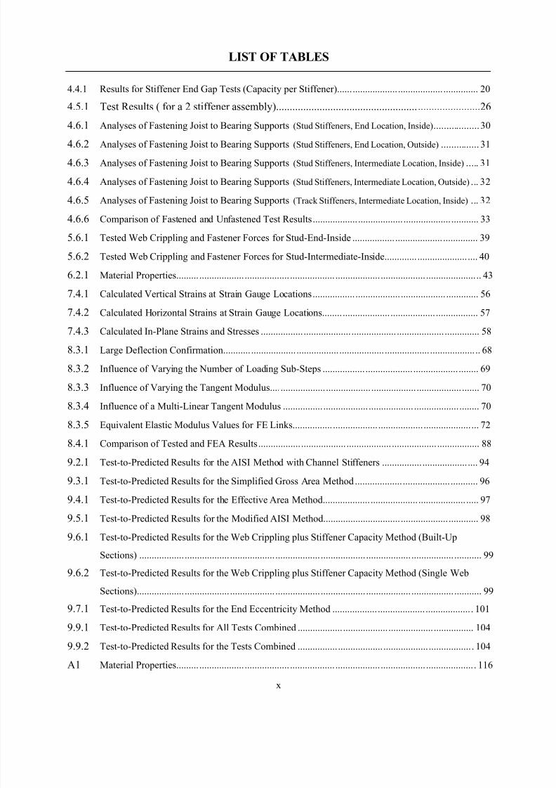
the photograph in Figure 1.1.1 and the details are illustrated in Figure 1.1.2.
Figure 1.1.1: Photograph Showing LSF Residential Construction
8/2/2019 Design of Bearing Stiffeners in Cold Formed C-Sections
http://slidepdf.com/reader/full/design-of-bearing-stiffeners-in-cold-formed-c-sections 16/151
2
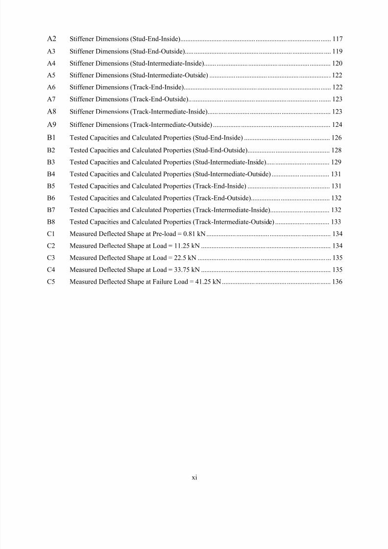
Figure 1.1.2: LSF Platform Construction Details
There is a tremendous business opportunity in residential construction that the North American steel
industry is trying to capitalize upon. This expanded interest in utilizing LSF has raised a number of
questions with engineers about the proper design procedures for these types of structures. One specific
area of interest concerns the design of bearing stiffeners for LSF floor joists.
LSF floor joists are typically C-sections ranging in depth from 150 to 356 mm (6 to 14 in.). The thin sheet
steel makes these sections prone to web buckling (or web crippling) under fairly low concentrated loads.
Such concentrated loads occur at every support or every location where a floor joist supports a
loadbearing wall above. To avoid the capacity reductions that the web crippling limit state would impose,
bearing stiffeners (or web stiffeners) are attached to the joist to transfer these loads.
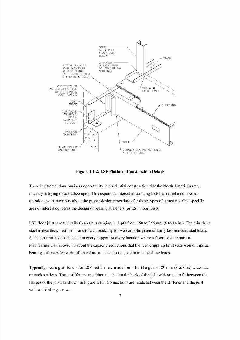
Typically, bearing stiffeners for LSF sections are made from short lengths of 89 mm (3-5/8 in.) wide stud
or track sections. These stiffeners are either attached to the back of the joist web or cut to fit between the
flanges of the joist, as shown in Figure 1.1.3. Connections are made between the stiffener and the joist
with self-drilling screws.
8/2/2019 Design of Bearing Stiffeners in Cold Formed C-Sections
http://slidepdf.com/reader/full/design-of-bearing-stiffeners-in-cold-formed-c-sections 17/151
3
Figure 1.1.3: Photograph of Bearing Stiffeners
1.2 RESEARCH OBJECTIVE AND SCOPE
The objective of this work was to understand the behavior of cold formed steel C-sections with bearing
stiffeners, and to develop design expressions for the end and interior two-flange loading of assemblies
typically used in LSF construction. The resulting design expressions will be submitted to the AISI and
CSA specification committees for consideration as new specification provisions. This objective has been
met through a combination of experiment, finite element analysis and analytical work.
The experimental work has included a total of 263 tests of stiffened C-section joist assemblies subjected
to end and interior two-flange loading. These tests have provided data on the following parameters:
• Joist depths up to 356 mm (14 in.) and web slenderness up to 300
• Stiffener type (stud, track, bridging channel)
• Location of the stiffener on the joist (between the flanges or on the back of the joist web)
• Position of the stiffener along the joist length (at the joist end or an intermediate position)
• Fastener pattern connecting the stiffener to the joist web
• Amount of gap between the end of the stiffener and the joist flanges
• Bearing width
• Web crippling capacity of the joist as a serviceability limit state
In addition to these assembly tests, additional tests were carried out to investigate the following
parameters:
• Strain gauge measurements of the stiffener during the loading cycle
8/2/2019 Design of Bearing Stiffeners in Cold Formed C-Sections
http://slidepdf.com/reader/full/design-of-bearing-stiffeners-in-cold-formed-c-sections 18/151
4
• Strain gauge and deflection measurements of the joist web during the loading cycle
• Measurements of the forces in the fasteners connecting the stiffener to the joist web
These measurements were used to develop the analytical model of the stiffened assembly and to calibrate
a finite element model. The FE modeling was used to determine the forces in the fasteners for various
fastener configurations as well as determine the web crippling capacity of the joist.
8/2/2019 Design of Bearing Stiffeners in Cold Formed C-Sections
http://slidepdf.com/reader/full/design-of-bearing-stiffeners-in-cold-formed-c-sections 19/151
5
2 EARLIER WORK
2.1 NGUYEN & YU, 1978
2.1.1 Background
In 1973, a research project at the University of Missouri-Rolla was sponsored by the American Iron and
Steel Institute titled “Webs for Cold-Formed Steel Flexural Members”. The purpose of this multi-phase
project was to study the structural behavior of unreinforced and reinforced beam webs subjected to
bending stress, shear stress, web crippling load and combinations thereof. At the time, neither the AISI
Specification [1] nor CSA-S136 Standard [2] included any specific design provisions for reinforced webs.
The results of this work are included in the following references: LaBoube & Yu [3, 4, 5], Hetrakul & Yu
[6] and Nguyen & Yu [7,8]. The work by Nguyen & Yu [7] was the first to study transversely stiffened
cold formed steel sections. This work will be described in more detail since it forms the basis of thecurrent specification design provisions.
The objectives of the test program of Nguyen & Yu was to study the structural behavior of reinforced
beam webs subjected to bending stress, shear stress, web crippling load and combinations thereof. This
was important at the time since the governing AISI Specification did not include any specific design
provisions for reinforced beam webs. Reinforced webs were necessary to extend the applicability of the
specification beyond the h/t limit of 200. The investigation was directed toward the study of the load
carrying capacity of transverse stiffeners located within the spans, or at the ends of the beam members,
and subjected directly to concentrated loads or reactions.
The design practice of the time recognized that the load carrying capacity of transverse stiffeners, when
provided at the locations of the applied loads or reactions, could be determined on the basis of column
formulae that included an adjacent portion of the web as a part of the stiffener column. The determination
of this effective portion of the web was very complicated for analytical analysis because it would involve
the web crippling strength of a combination of beam web and stiffener, the elastic and inelastic instability
of the stiffener, and the local buckling of the plate elements of the stiffener. For these reasons, Nguyen &
Yu undertook an experimental study to provide the data needed to formulate design provisions for cold
formed steel transverse stiffeners.
2.1.2 Summary of Test Specimens
The tests were carried out on C-section specimens tested in pairs back-to-back, separated by pieces of
cold formed angles attached to the flanges. The specimens were also restrained from lateral movement to
prevent lateral-torsional buckling. The load was located either directly over the interior stiffener or the
8/2/2019 Design of Bearing Stiffeners in Cold Formed C-Sections
http://slidepdf.com/reader/full/design-of-bearing-stiffeners-in-cold-formed-c-sections 20/151
6
end stiffener depending on the test series. For all of these tests the stiffener was located on the back of the
joist web and connected with either 19 mm (3/4 in.) bolts or #12x14 self-tapping Tek screws. The C-
section joist members had web depth to thickness ratios (h/t) from 150 to 300 and depths from 150 to 535
mm (6 to 21 in.). The test set-up is shown in Figure 2.1.1. In total, 33 tests were carried out on
intermediate stiffeners and 28 tests on end stiffeners.
The transverse stiffeners were proportioned so that there would be no local buckling of any sub-element.
The stiffeners were unlipped C-sections with a flange width of 12.7 mm (0.5 in.), a web depth of 38 mm
(1.5 in.) and thickness of 1.02 mm (0.040 in.). Strain gauges were attached to points on the stiffener as
well as the beam web to measure the stress distribution, and were also used to ensure the loading was
concentric on the stiffener.
Figure 2.1.1: Nguyen & Yu Test Set-up
P
Hydraulic jack
Load cell
Box beam specimen
P
Elastic support
Transverse
stiffener
Test setup for end transverse stiffener tests
Test setup for intermediate transverse stiffener tests
P P
Hydraulic jack
Load cell
Box beam specimen
Transverse
stiffener
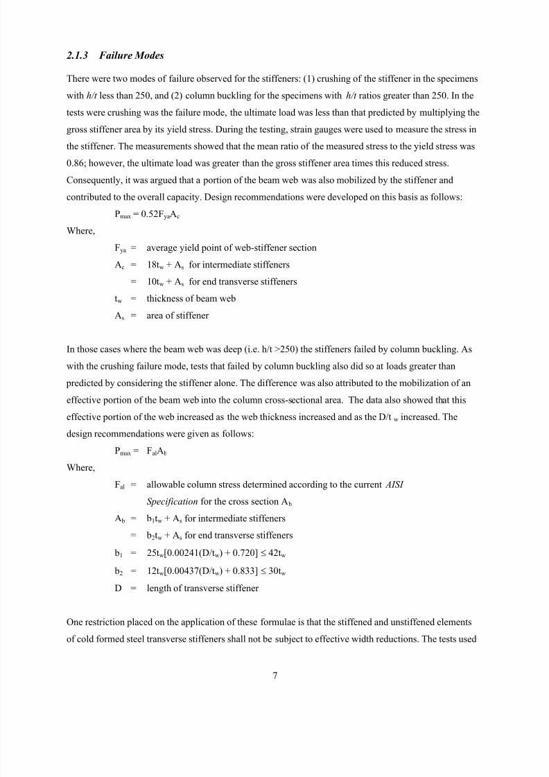
8/2/2019 Design of Bearing Stiffeners in Cold Formed C-Sections
http://slidepdf.com/reader/full/design-of-bearing-stiffeners-in-cold-formed-c-sections 21/151
7
2.1.3 Failure Modes
There were two modes of failure observed for the stiffeners: (1) crushing of the stiffener in the specimens
with h/t less than 250, and (2) column buckling for the specimens with h/t ratios greater than 250. In the
tests were crushing was the failure mode, the ultimate load was less than that predicted by multiplying the
gross stiffener area by its yield stress. During the testing, strain gauges were used to measure the stress in
the stiffener. The measurements showed that the mean ratio of the measured stress to the yield stress was
0.86; however, the ultimate load was greater than the gross stiffener area times this reduced stress.
Consequently, it was argued that a portion of the beam web was also mobilized by the stiffener and
contributed to the overall capacity. Design recommendations were developed on this basis as follows:
Pmax = 0.52FyaAc
Where,
Fya = average yield point of web-stiffener section
Ac = 18tw + As for intermediate stiffeners
= 10tw + As for end transverse stiffeners
tw = thickness of beam web
As = area of stiffener
In those cases where the beam web was deep (i.e. h/t >250) the stiffeners failed by column buckling. As
with the crushing failure mode, tests that failed by column buckling also did so at loads greater than
predicted by considering the stiffener alone. The difference was also attributed to the mobilization of an
effective portion of the beam web into the column cross-sectional area. The data also showed that this
effective portion of the web increased as the web thickness increased and as the D/tw increased. The
design recommendations were given as follows:
Pmax = FalA b
Where,
Fal = allowable column stress determined according to the current AISI
Specification for the cross section A b
A b = b1tw + As for intermediate stiffeners
= b2tw + As for end transverse stiffeners
b1 = 25tw[0.00241(D/tw) + 0.720] ≤ 42tw
b2 = 12tw[0.00437(D/tw) + 0.833] ≤ 30tw
D = length of transverse stiffener
One restriction placed on the application of these formulae is that the stiffened and unstiffened elements
of cold formed steel transverse stiffeners shall not be subject to effective width reductions. The tests used
8/2/2019 Design of Bearing Stiffeners in Cold Formed C-Sections
http://slidepdf.com/reader/full/design-of-bearing-stiffeners-in-cold-formed-c-sections 22/151
8
a stiffener section that was 38 mm (1-1/2 in.) wide with 12 mm (1/2 in.) flanges, which are sections used
today for through-the-knockout bridging, but not normally considered as stiffeners.
2.1.4 Conclusions by Nguyen & Yu
(a) The strength of transverse stiffeners alone provide a very conservative result in predicting the load
carrying capacity of beam webs loaded at the locations of the transverse stiffeners.
(b) A portion of the beam web contributes to the load carrying capacity of the web-stiffener column.
(c) Short stiffeners usually failed by end crushing at a stress less than that of the yield point of the
stiffener steel.
(d) Stability failure occurred for long transverse stiffeners, and the effective width of beam webs depends
on the web thickness and the D/tw ratio of the steel beam.
(e) Connections between the beam webs and the transverse stiffeners have a significant effect on the
behavior of the transverse stiffeners.
(f) On the basis of the experimental data obtained, design formulae were derived to compute the
effective widths of beam webs for intermediate and end transverse stiffeners under end crushing and
stability failure.
(g) The column design criteria in the AISI Specification can be used to predict the ultimate load of a
web-stiffener assembly column.
As a recommendation of their work, Nguyen & Yu [7] proposed formulae (given above) for the design of
transverse stiffeners when they are provided at the location of applied loads or reactions. These formulae,
in a modified form, are currently in both the AISI Specification [1] and the CSA-S136 Standard [2], and
are presented in Section 2.2.
2.2 CURRENT BEARING STIFFENER DESIGN PROVISIONS AND LIMITATIONS
The provisions of AISI Specification Section B6.1 Transverse Stiffeners are as follows:
“Transverse stiffeners attached to beam webs at points of concentrated loads or reactions shall be
designed as compressive members. Concentrated loads or reactions shall be applied directly into the
stiffeners or each stiffener shall be fitted accurately to the flat portion of the flange to provide direct load-
bearing into the end of the stiffener. Means of shear transfer between the stiffener and the web shall be
provided according to Chapter E. For concentrated loads or reactions the nominal strength equals P n ,
where P n is the smaller value given by (a) and (b) as follows:
(a) P r = F wy Ac
(b) P n = Nominal axial strength evaluated according to Section C4(a), with Ae replaced by Ab
c = 2.0 (ASD)
c = 0.86 (LRFD)
8/2/2019 Design of Bearing Stiffeners in Cold Formed C-Sections
http://slidepdf.com/reader/full/design-of-bearing-stiffeners-in-cold-formed-c-sections 23/151
9
Where,
Ac = 18t 2 + A s , for transverse stiffeners at interior support and under concentrated load
Ac = 10t 2 + A s , for transverse stiffeners at end support
F wy = Lower value of F y for the beam web, or F ys for the stiffener section
Ab = b1t + A s , for transverse stiffeners at interior support and under concentrated load
Ab = b2t + A s , for transverse stiffeners at end support
A s = Cross-sectional area of transverse stiffener
b1 = 25t[0.0024(L st /t) + 0.72] ≤ 25t
b2 = 12t[0.0044(L st /t) + 0.83] ≤ 12t
L st = total length of transverse stiffener
t = thickness of beam web
The w/t s ratio for the stiffened and unstiffened elements of cold-formed steel transverse stiffeners shall not
exceed ysF/E28.1 and ysF/E37.0 , respectively, where F ys is the yield stress, and t s is the thickness of
the stiffener steel.”
In AISI Specification [1] Chapter B1.2, it also specifies that (h/t)max = 200 for unreinforced webs. This
means that for the deeper LSF sections some type of web stiffener is a mandatory requirement of the
Specification. The same provisions are also included in the CSA-S136 Standard [2].
2.3 NEED FOR ADDITIONAL RESEARCH
The requirements in the Specification are quite clear; when h/t exceeds 200 a stiffener is required for unreinforced webs and the design rules are given. However, there are two practical problems with these
requirements. The most significant issue is the condition that the flat width of any element in the stiffener
shall not exceed the limit for local buckling. This means that no element in the stiffener can be subject to
effective width reductions. This condition is not met by any of the stiffeners in common use today. A LSF
stud or track section as a bearing stiffener will be subject to effective width reductions at modest stress
levels and fall outside the provisions of the Standard.
A second problem arises from the condition that the stiffener must be fitted accurately to the flange to
provided direct load bearing. It is common practice to cut the stiffener shorter than the inside dimension
between the flanges to facilitate construction: a condition that would not satisfy the Specification
requirement that the stiffener is to be fitted accurately.
The designer, therefore, must use engineering judgment or tests to arrive at an appropriate design method
if the thin LSF stiffener sections are being used. Common engineering practice is to consider these
members not as transverse stiffeners, but as short concentrically loaded columns transferring point loads
8/2/2019 Design of Bearing Stiffeners in Cold Formed C-Sections
http://slidepdf.com/reader/full/design-of-bearing-stiffeners-in-cold-formed-c-sections 24/151
10
across the member. This column member also happens to be connected to the joist web, which stiffens the
web to prevent web crippling. It could be argued, however, that the requirements of the Specification are
not being met. This ambiguity was one of the reasons the AISI and CSSBI technical committees were
interested in a research project to develop design procedures applicable to the types of stiffeners being
used in LSF construction today.
8/2/2019 Design of Bearing Stiffeners in Cold Formed C-Sections
http://slidepdf.com/reader/full/design-of-bearing-stiffeners-in-cold-formed-c-sections 25/151
11
3 GENERAL DESCRIPTION OF TEST PROCEDURES
3.1 TEST SET-UP
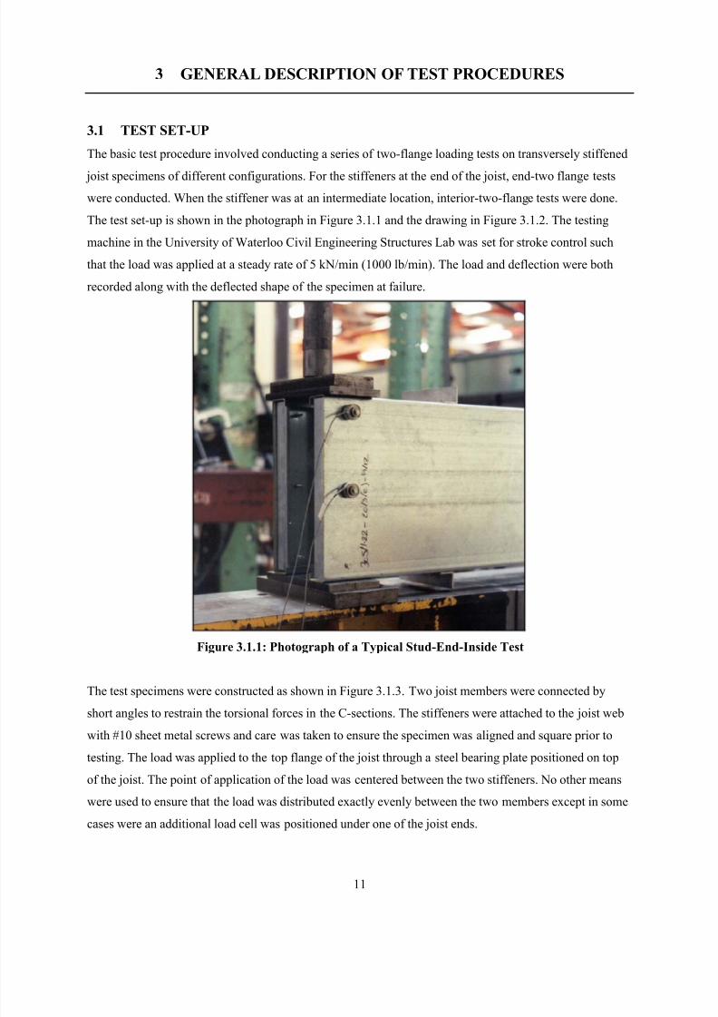
The basic test procedure involved conducting a series of two-flange loading tests on transversely stiffened
joist specimens of different configurations. For the stiffeners at the end of the joist, end-two flange tests
were conducted. When the stiffener was at an intermediate location, interior-two-flange tests were done.
The test set-up is shown in the photograph in Figure 3.1.1 and the drawing in Figure 3.1.2. The testing
machine in the University of Waterloo Civil Engineering Structures Lab was set for stroke control such
that the load was applied at a steady rate of 5 kN/min (1000 lb/min). The load and deflection were both
recorded along with the deflected shape of the specimen at failure.
Figure 3.1.1: Photograph of a Typical Stud-End-Inside Test
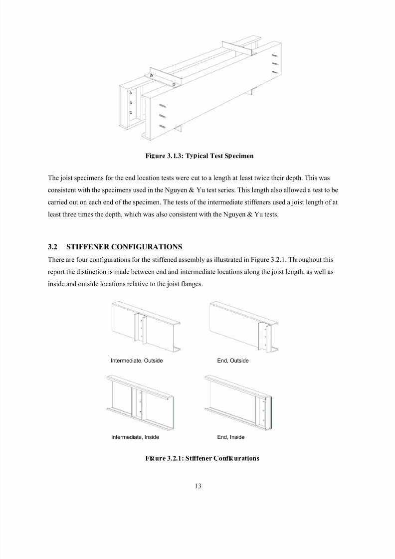
The test specimens were constructed as shown in Figure 3.1.3. Two joist members were connected by
short angles to restrain the torsional forces in the C-sections. The stiffeners were attached to the joist web
with #10 sheet metal screws and care was taken to ensure the specimen was aligned and square prior to
testing. The load was applied to the top flange of the joist through a steel bearing plate positioned on top
of the joist. The point of application of the load was centered between the two stiffeners. No other means
were used to ensure that the load was distributed exactly evenly between the two members except in some
cases were an additional load cell was positioned under one of the joist ends.
8/2/2019 Design of Bearing Stiffeners in Cold Formed C-Sections
http://slidepdf.com/reader/full/design-of-bearing-stiffeners-in-cold-formed-c-sections 26/151
12
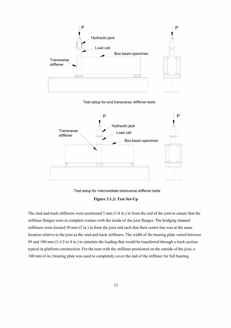
Figure 3.1.2: Test Set-Up
The stud and track stiffeners were positioned 5 mm (1/4 in.) in from the end of the joist to ensure that the
stiffener flanges were in complete contact with the inside of the joist flanges. The bridging channel
stiffeners were located 50 mm (2 in.) in from the joist end such that their center line was at the same
location relative to the joist as the stud and track stiffeners. The width of the bearing plate varied between
89 and 100 mm (3-1/2 to 4 in.) to simulate the loading that would be transferred through a track section
typical in platform construction. For the tests with the stiffener positioned on the outside of the joist, a
100 mm (4 in.) bearing plate was used to completely cover the end of the stiffener for full bearing.
P
Hydraulic jack
Load cell
Box beam specimen
P
Transverse
stiffener
Test setup for end transverse stiffener tests
Test setup for intermediate transverse stiffener tests
P
Hydraulic jack
Load cell
Box beam specimen
Transverse
stiffener
P
8/2/2019 Design of Bearing Stiffeners in Cold Formed C-Sections
http://slidepdf.com/reader/full/design-of-bearing-stiffeners-in-cold-formed-c-sections 27/151
13
The joist specimens for the end location tests were cut to a length at least twice their depth. This was
consistent with the specimens used in the Nguyen & Yu test series. This length also allowed a test to be
carried out on each end of the specimen. The tests of the intermediate stiffeners used a joist length of at
least three times the depth, which was also consistent with the Nguyen & Yu tests.
3.2 STIFFENER CONFIGURATIONS
There are four configurations for the stiffened assembly as illustrated in Figure 3.2.1. Throughout this
report the distinction is made between end and intermediate locations along the joist length, as well as
inside and outside locations relative to the joist flanges.
Intermediate, Inside End, Inside
Intermediate, Outside End, Outside
Fi ure 3.2.1: Stiffener Confi urations
Fi ure 3.1.3: T ical Test S ecimen
8/2/2019 Design of Bearing Stiffeners in Cold Formed C-Sections
http://slidepdf.com/reader/full/design-of-bearing-stiffeners-in-cold-formed-c-sections 28/151
14
4 EXPERIMENTAL TEST RESULTS AND ANALYSIS
4.1 INTRODUCTION
Described in the following sections are the general failure modes and findings arising from observations
of the different test series conducted.
4.2 GENERAL FAILURE DEFORMATION
Many of the tests were conducted on bearing stiffeners attached to the joist web between the joist flanges.
This location forces the applied load to be transferred to the stiffener through bearing on the underside of
the joist flange. A key factor in the behavior of this assembly is the gap between the end of the stiffener
and the joist.
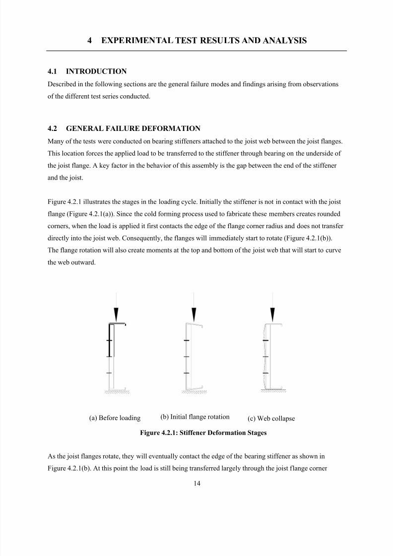
Figure 4.2.1 illustrates the stages in the loading cycle. Initially the stiffener is not in contact with the joist
flange (Figure 4.2.1(a)). Since the cold forming process used to fabricate these members creates rounded
corners, when the load is applied it first contacts the edge of the flange corner radius and does not transfer
directly into the joist web. Consequently, the flanges will immediately start to rotate (Figure 4.2.1(b)).
The flange rotation will also create moments at the top and bottom of the joist web that will start to curve
the web outward.
As the joist flanges rotate, they will eventually contact the edge of the bearing stiffener as shown in
Figure 4.2.1(b). At this point the load is still being transferred largely through the joist flange corner
(a) Before loading (b) Initial flange rotation (c) Web collapse
Figure 4.2.1: Stiffener Deformation Stages
8/2/2019 Design of Bearing Stiffeners in Cold Formed C-Sections
http://slidepdf.com/reader/full/design-of-bearing-stiffeners-in-cold-formed-c-sections 29/151
15
radius into the web. There comes a point, however, when the compressive force in the web, combined
with the bending moment caused by loading the corner radius, causes the web to buckle. Once the web
buckles (i.e. web crippling) it has little post-buckling strength and the assembly will not carry any
significant extra load until the flange comes in full contact with the end of the stiffener (Figure 4.2.1 (c)).
From this point onward the additional load is transferred directly into the stiffener through end bearing.
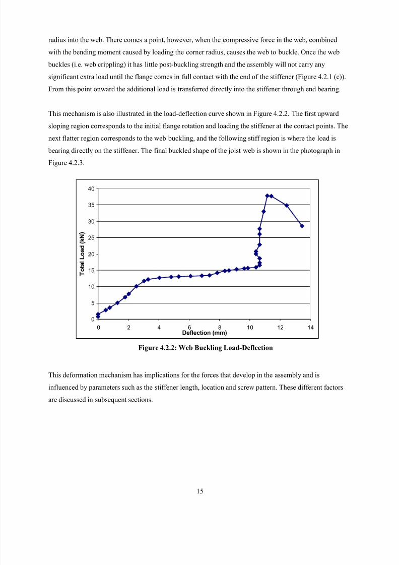
This mechanism is also illustrated in the load-deflection curve shown in Figure 4.2.2. The first upward
sloping region corresponds to the initial flange rotation and loading the stiffener at the contact points. The
next flatter region corresponds to the web buckling, and the following stiff region is where the load is
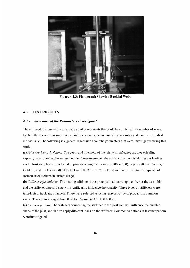
bearing directly on the stiffener. The final buckled shape of the joist web is shown in the photograph in
Figure 4.2.3.
This deformation mechanism has implications for the forces that develop in the assembly and is
influenced by parameters such as the stiffener length, location and screw pattern. These different factors
are discussed in subsequent sections.
0
5
10
15
20
25
30
35
40
0 2 4 6 8 10 12 14Deflection (mm)
T o t a l L o a d
( k N )
Figure 4.2.2: Web Buckling Load-Deflection
8/2/2019 Design of Bearing Stiffeners in Cold Formed C-Sections
http://slidepdf.com/reader/full/design-of-bearing-stiffeners-in-cold-formed-c-sections 30/151
16
Figure 4.2.3: Photograph Showing Buckled Webs
4.3 TEST RESULTS
4.3.1 Summary of the Parameters Investigated
The stiffened joist assembly was made up of components that could be combined in a number of ways.
Each of these variations may have an influence on the behaviour of the assembly and have been studied
individually. The following is a general discussion about the parameters that were investigated during this
study.
(a) Joist depth and thickness: The depth and thickness of the joist will influence the web crippling
capacity, post-buckling behaviour and the forces exerted on the stiffener by the joist during the loading
cycle. Joist samples were selected to provide a range of h/t ratios (100 to 300), depths (203 to 356 mm, 8
to 14 in.) and thicknesses (0.84 to 1.91 mm, 0.033 to 0.075 in.) that were representative of typical cold
formed steel sections in current usage.
(b) Stiffener type and size: The bearing stiffener is the principal load-carrying member in the assembly,
and the stiffener type and size will significantly influence the capacity. Three types of stiffeners were
tested: stud, track and channels. These were selected as being representative of products in common
usage. Thicknesses ranged from 0.80 to 1.52 mm (0.031 to 0.060 in.)
(c) Fastener pattern: The fasteners connecting the stiffener to the joist web will influence the buckled
shape of the joist, and in turn apply different loads on the stiffener. Common variations in fastener pattern
were investigated.
8/2/2019 Design of Bearing Stiffeners in Cold Formed C-Sections
http://slidepdf.com/reader/full/design-of-bearing-stiffeners-in-cold-formed-c-sections 31/151
17
(d) End gap between stiffener and joist flange: When the stiffener is positioned between the joist flanges,
it is commonly cut short to facilitate installation. The effect of this gap between the stiffener and the joist
was investigated to determine what affect it had on the capacity of the assembly.
(e) Bearing width: The stiffened assembly was subjected to two-flange loading and the stiffener was
acting as a short column. If the bearing width is less then the width of the stiffener, the capacity of the
stiffener will be affected.
(f) Fastening joist flange to the support : In other web crippling studies it has been determined that
fastening the flanges of the specimen to the supports can have a measurable affect on the capacity of the
section. Tests were carried out to compare the influence of fastening the joist flange to the support in a
stiffened assembly.
(g) Reaction at the free end of the test specimen: During the tests the specimen rested on two bearing
supports but loaded only at one end. Measurements were taken of the load at the unloaded support to
determine whether two load cells would be needed to determine the failure load.
(h) Web crippling capacity of the joist : One of the serviceability limit states of these type of assemblies
would be the web crippling capacity of the joist. This would be significant for those assemblies with the
stiffener positioned between the joist flanges and cut shorted than the depth of the joist.
(i) Fastener forces: The buckling of the joist web is restrained by the fasteners connecting the joist to the
stiffener. The number and location of the fasteners, the size of the joist web, and size of the stiffener will
determine what forces are developed and transferred to the stiffener. The capacity of the stiffener will in
turn be affected by these added lateral forces.
4.3.2 Material properties and Dimensions
Tables A1 through A9 list the material properties and the stiffener dimensions for all of the tests. The joist
sections varied in depth (as indicated in Tables B1 through B8) but in each case had a nominal flange
width of 41 mm (1-5/8 in.) with 12 mm (1/2 in.) lips.
4.3.3 Tested Bearing Capacities\
Tables B1 through B8 provide all of the tested capacities. These tables will be referred to in the following
sections as various specific studies are discussed. The tested capacities are analyzed in more detail in
Section 9 were the various prediction methods are considered.
8/2/2019 Design of Bearing Stiffeners in Cold Formed C-Sections
http://slidepdf.com/reader/full/design-of-bearing-stiffeners-in-cold-formed-c-sections 32/151
18
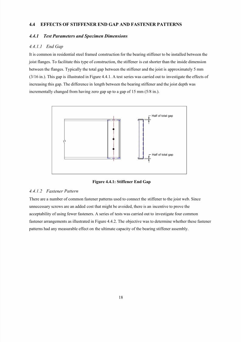
4.4 EFFECTS OF STIFFENER END GAP AND FASTENER PATTERNS
4.4.1 Test Parameters and Specimen Dimensions
4.4.1.1 End Gap
It is common in residential steel framed construction for the bearing stiffener to be installed between the
joist flanges. To facilitate this type of construction, the stiffener is cut shorter than the inside dimension
between the flanges. Typically the total gap between the stiffener and the joist is approximately 5 mm
(3/16 in.). This gap is illustrated in Figure 4.4.1. A test series was carried out to investigate the effects of
increasing this gap. The difference in length between the bearing stiffener and the joist depth was
incrementally changed from having zero gap up to a gap of 15 mm (5/8 in.).
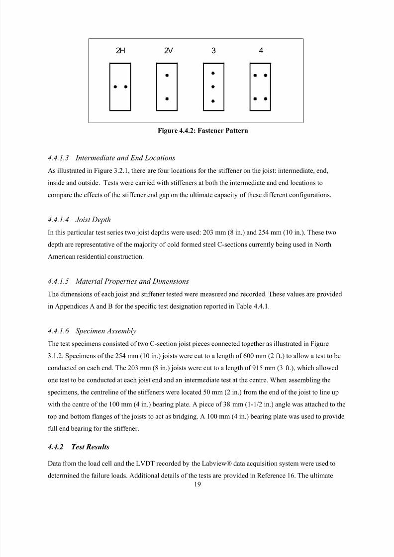
4.4.1.2 Fastener Pattern
There are a number of common fastener patterns used to connect the stiffener to the joist web. Since
unnecessary screws are an added cost that might be avoided, there is an incentive to prove the
acceptability of using fewer fasteners. A series of tests was carried out to investigate four common
fastener arrangements as illustrated in Figure 4.4.2. The objective was to determine whether these fastener
patterns had any measurable effect on the ultimate capacity of the bearing stiffener assembly.
Half of total gap
Half of total gap
Figure 4.4.1: Stiffener End Gap
8/2/2019 Design of Bearing Stiffeners in Cold Formed C-Sections
http://slidepdf.com/reader/full/design-of-bearing-stiffeners-in-cold-formed-c-sections 33/151
19
4.4.1.3 Intermediate and End Locations
As illustrated in Figure 3.2.1, there are four locations for the stiffener on the joist: intermediate, end,
inside and outside. Tests were carried with stiffeners at both the intermediate and end locations to
compare the effects of the stiffener end gap on the ultimate capacity of these different configurations.
4.4.1.4 Joist Depth
In this particular test series two joist depths were used: 203 mm (8 in.) and 254 mm (10 in.). These two
depth are representative of the majority of cold formed steel C-sections currently being used in North
American residential construction.
4.4.1.5 Material Properties and Dimensions
The dimensions of each joist and stiffener tested were measured and recorded. These values are provided
in Appendices A and B for the specific test designation reported in Table 4.4.1.
4.4.1.6 Specimen Assembly
The test specimens consisted of two C-section joist pieces connected together as illustrated in Figure
3.1.2. Specimens of the 254 mm (10 in.) joists were cut to a length of 600 mm (2 ft.) to allow a test to be
conducted on each end. The 203 mm (8 in.) joists were cut to a length of 915 mm (3 ft.), which allowed
one test to be conducted at each joist end and an intermediate test at the centre. When assembling the
specimens, the centreline of the stiffeners were located 50 mm (2 in.) from the end of the joist to line up
with the centre of the 100 mm (4 in.) bearing plate. A piece of 38 mm (1-1/2 in.) angle was attached to the
top and bottom flanges of the joists to act as bridging. A 100 mm (4 in.) bearing plate was used to provide
full end bearing for the stiffener.
4.4.2 Test Results
Data from the load cell and the LVDT recorded by the Labview® data acquisition system were used to
determined the failure loads. Additional details of the tests are provided in Reference 16. The ultimate
2H 2V 43
Figure 4.4.2: Fastener Pattern
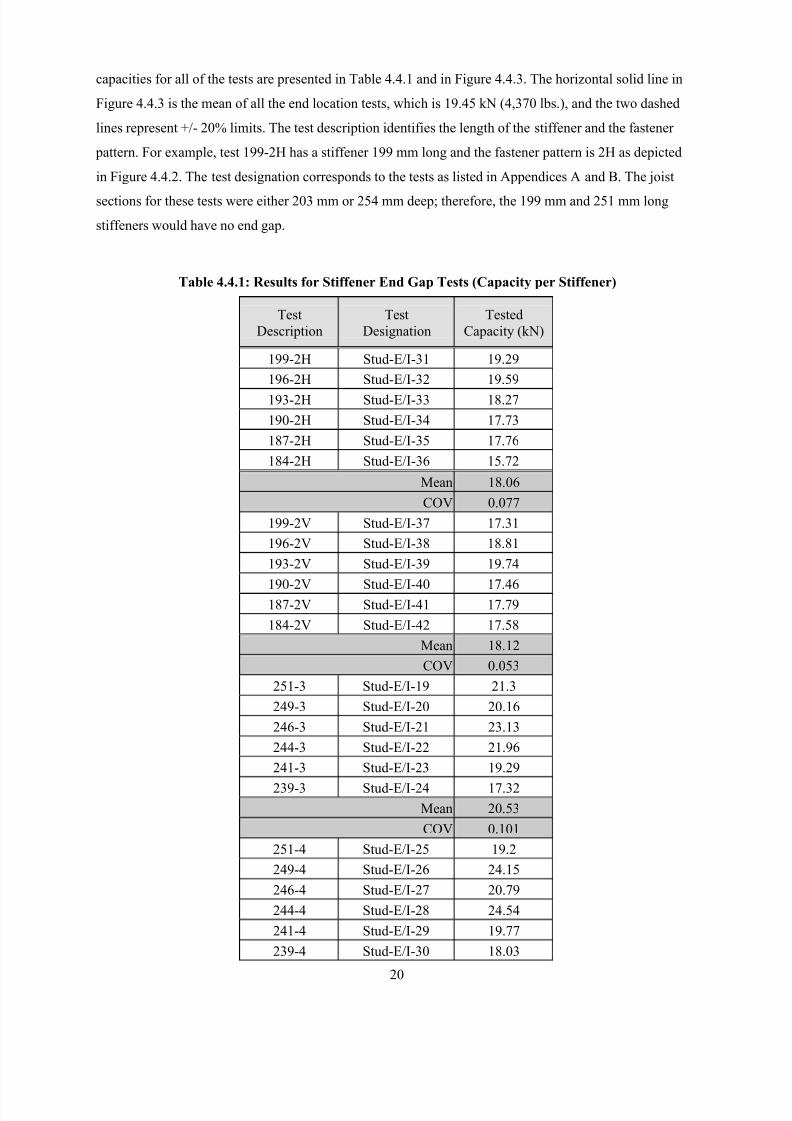
8/2/2019 Design of Bearing Stiffeners in Cold Formed C-Sections
http://slidepdf.com/reader/full/design-of-bearing-stiffeners-in-cold-formed-c-sections 34/151
20
capacities for all of the tests are presented in Table 4.4.1 and in Figure 4.4.3. The horizontal solid line in
Figure 4.4.3 is the mean of all the end location tests, which is 19.45 kN (4,370 lbs.), and the two dashed
lines represent +/- 20% limits. The test description identifies the length of the stiffener and the fastener
pattern. For example, test 199-2H has a stiffener 199 mm long and the fastener pattern is 2H as depicted
in Figure 4.4.2. The test designation corresponds to the tests as listed in Appendices A and B. The joist
sections for these tests were either 203 mm or 254 mm deep; therefore, the 199 mm and 251 mm long
stiffeners would have no end gap.
Table 4.4.1: Results for Stiffener End Gap Tests (Capacity per Stiffener)
Test
Description
Test
Designation
Tested
Capacity (kN)
199-2H Stud-E/I-31 19.29
196-2H Stud-E/I-32 19.59
193-2H Stud-E/I-33 18.27
190-2H Stud-E/I-34 17.73
187-2H Stud-E/I-35 17.76
184-2H Stud-E/I-36 15.72
Mean 18.06
COV 0.077
199-2V Stud-E/I-37 17.31
196-2V Stud-E/I-38 18.81
193-2V Stud-E/I-39 19.74
190-2V Stud-E/I-40 17.46187-2V Stud-E/I-41 17.79
184-2V Stud-E/I-42 17.58
Mean 18.12
COV 0.053
251-3 Stud-E/I-19 21.3
249-3 Stud-E/I-20 20.16
246-3 Stud-E/I-21 23.13
244-3 Stud-E/I-22 21.96
241-3 Stud-E/I-23 19.29
239-3 Stud-E/I-24 17.32
Mean 20.53
COV 0.101
251-4 Stud-E/I-25 19.2
249-4 Stud-E/I-26 24.15
246-4 Stud-E/I-27 20.79
244-4 Stud-E/I-28 24.54
241-4 Stud-E/I-29 19.77
239-4 Stud-E/I-30 18.03
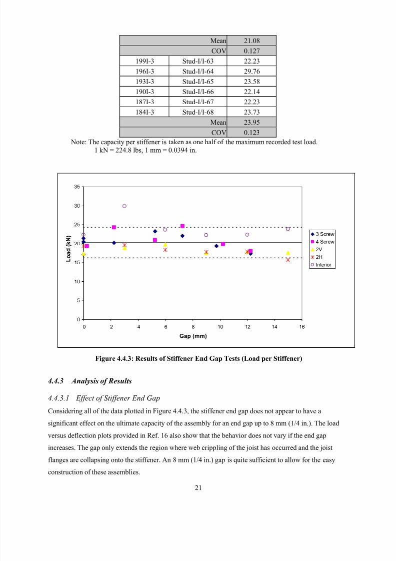
8/2/2019 Design of Bearing Stiffeners in Cold Formed C-Sections
http://slidepdf.com/reader/full/design-of-bearing-stiffeners-in-cold-formed-c-sections 35/151
21
Mean 21.08
COV 0.127
199I-3 Stud-I/I-63 22.23
196I-3 Stud-I/I-64 29.76
193I-3 Stud-I/I-65 23.58
190I-3 Stud-I/I-66 22.14
187I-3 Stud-I/I-67 22.23
184I-3 Stud-I/I-68 23.73
Mean 23.95
COV 0.123
Note: The capacity per stiffener is taken as one half of the maximum recorded test load.
1 kN = 224.8 lbs, 1 mm = 0.0394 in.
Figure 4.4.3: Results of Stiffener End Gap Tests (Load per Stiffener)
4.4.3 Analysis of Results
4.4.3.1 Effect of Stiffener End Gap
Considering all of the data plotted in Figure 4.4.3, the stiffener end gap does not appear to have a
significant effect on the ultimate capacity of the assembly for an end gap up to 8 mm (1/4 in.). The load
versus deflection plots provided in Ref. 16 also show that the behavior does not vary if the end gap
increases. The gap only extends the region where web crippling of the joist has occurred and the joist
flanges are collapsing onto the stiffener. An 8 mm (1/4 in.) gap is quite sufficient to allow for the easy
construction of these assemblies.
0
5
10
15
20
25
30
35
0 2 4 6 8 10 12 14 16
Gap (mm)
L o a d
( k N ) 3 Screw
4 Screw
2V
2H
Interior
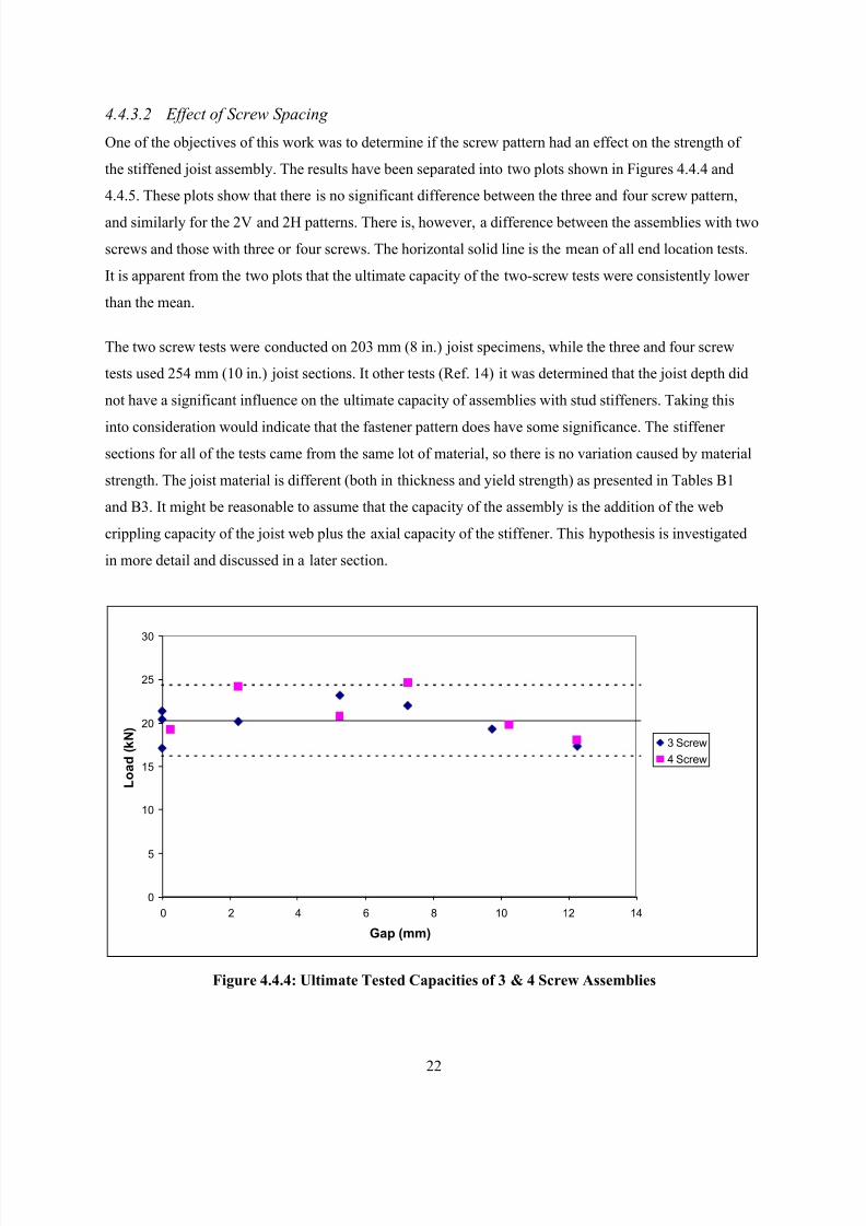
8/2/2019 Design of Bearing Stiffeners in Cold Formed C-Sections
http://slidepdf.com/reader/full/design-of-bearing-stiffeners-in-cold-formed-c-sections 36/151
22
4.4.3.2 Effect of Screw Spacing
One of the objectives of this work was to determine if the screw pattern had an effect on the strength of
the stiffened joist assembly. The results have been separated into two plots shown in Figures 4.4.4 and
4.4.5. These plots show that there is no significant difference between the three and four screw pattern,
and similarly for the 2V and 2H patterns. There is, however, a difference between the assemblies with two
screws and those with three or four screws. The horizontal solid line is the mean of all end location tests.
It is apparent from the two plots that the ultimate capacity of the two-screw tests were consistently lower
than the mean.
The two screw tests were conducted on 203 mm (8 in.) joist specimens, while the three and four screw
tests used 254 mm (10 in.) joist sections. It other tests (Ref. 14) it was determined that the joist depth did
not have a significant influence on the ultimate capacity of assemblies with stud stiffeners. Taking this
into consideration would indicate that the fastener pattern does have some significance. The stiffener
sections for all of the tests came from the same lot of material, so there is no variation caused by material
strength. The joist material is different (both in thickness and yield strength) as presented in Tables B1
and B3. It might be reasonable to assume that the capacity of the assembly is the addition of the web
crippling capacity of the joist web plus the axial capacity of the stiffener. This hypothesis is investigated
in more detail and discussed in a later section.
Figure 4.4.4: Ultimate Tested Capacities of 3 & 4 Screw Assemblies
0
5
10
15
20
25
30
0 2 4 6 8 10 12 14
Gap (mm)
L o a d
( k N )
3 Screw
4 Screw
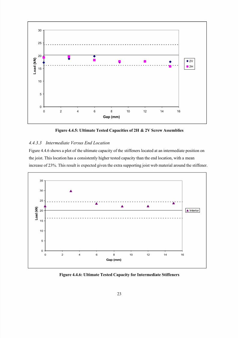
8/2/2019 Design of Bearing Stiffeners in Cold Formed C-Sections
http://slidepdf.com/reader/full/design-of-bearing-stiffeners-in-cold-formed-c-sections 37/151
23
0
5
10
15
20
25
30
35
0 2 4 6 8 10 12 14 16
Gap (mm)
L o a d
( k N )
Interior
Figure 4.4.5: Ultimate Tested Capacities of 2H & 2V Screw Assemblies
4.4.3.3 Intermediate Versus End Location
Figure 4.4.6 shows a plot of the ultimate capacity of the stiffeners located at an intermediate position on
the joist. This location has a consistently higher tested capacity than the end location, with a mean
increase of 23%. This result is expected given the extra supporting joist web material around the stiffener.
Figure 4.4.6: Ultimate Tested Capacity for Intermediate Stiffeners
0
5
10
15
20
25
30
0 2 4 6 8 10 12 14 16
Gap (mm)
L o a d
( k N )
2V
2H
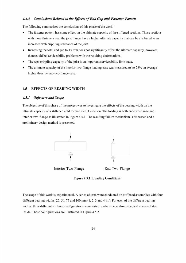
8/2/2019 Design of Bearing Stiffeners in Cold Formed C-Sections
http://slidepdf.com/reader/full/design-of-bearing-stiffeners-in-cold-formed-c-sections 38/151
24
4.4.4 Conclusions Related to the Effects of End Gap and Fastener Pattern
The following summarizes the conclusions of this phase of the work:
• The fastener pattern has some effect on the ultimate capacity of the stiffened sections. Those sections
with more fasteners near the joist flange have a higher ultimate capacity that can be attributed to an
increased web crippling resistance of the joist.
• Increasing the total end gap to 15 mm does not significantly affect the ultimate capacity, however,
there could be serviceability problems with the resulting deformations.
• The web crippling capacity of the joist is an important serviceability limit state.
• The ultimate capacity of the interior-two-flange loading case was measured to be 23% on average
higher than the end-two-flange case.
4.5 EFFECTS OF BEARING WIDTH
4.5.1 Objective and Scope
The objective of this phase of the project was to investigate the effects of the bearing width on the
ultimate capacity of a stiffened cold formed steel C-section. The loading is both end-two-flange and
interior-two-flange as illustrated in Figure 4.5.1. The resulting failure mechanism is discussed and a
preliminary design method is presented.
The scope of this work is experimental. A series of tests were conducted on stiffened assemblies with four
different bearing widths: 25, 50, 75 and 100 mm (1, 2, 3 and 4 in.). For each of the different bearing
widths, three different stiffener configurations were tested: end-inside, end-outside, and intermediate-
inside. These configurations are illustrated in Figure 4.5.2.
End-Two-FlangeInterior-Two-Flange
Figure 4.5.1: Loading Conditions
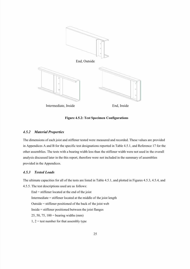
8/2/2019 Design of Bearing Stiffeners in Cold Formed C-Sections
http://slidepdf.com/reader/full/design-of-bearing-stiffeners-in-cold-formed-c-sections 39/151
25
4.5.2 Material Properties
The dimensions of each joist and stiffener tested were measured and recorded. These values are providedin Appendices A and B for the specific test designations reported in Table 4.5.1, and Reference 17 for the
other assemblies. The tests with a bearing width less than the stiffener width were not used in the overall
analysis discussed later in the this report, therefore were not included in the summary of assemblies
provided in the Appendices.
4.5.3 Tested Loads
The ultimate capacities for all of the tests are listed in Table 4.5.1, and plotted in Figures 4.5.3, 4.5.4, and
4.5.5. The test descriptions used are as follows:
End = stiffener located at the end of the joist
Intermediate = stiffener located at the middle of the joist length
Outside = stiffener positioned of the back of the joist web
Inside = stiffener positioned between the joist flanges
25, 50, 75, 100 = bearing widths (mm)
1, 2 = test number for that assembly type
Intermediate, Inside End, Inside
End, Outside
Figure 4.5.2: Test Specimen Configurations
8/2/2019 Design of Bearing Stiffeners in Cold Formed C-Sections
http://slidepdf.com/reader/full/design-of-bearing-stiffeners-in-cold-formed-c-sections 40/151
26
Table 4.5.1: Test Results ( for a 2 stiffener assembly)
Test
Description
Test
Designation
Tested
Capacity (kN)
End-25-Inside-1 N/A 27.54
End-25-Inside-2 N/A 24.54
End-50-Inside-1 N/A 27.96
End-50-Inside-2 N/A 27.00
End-75-Inside-1 N/A 33.72
End-75-Inside-2 N/A 28.80
End-100-Inside-1 Stud-E/I-45 44.22
End-100-Inside-2 Stud-E/I-46 45.12
End-25-Outside-1 N/A 23.88
End-25-Outside-2 N/A 20.88
End-50-Outside-1 N/A 27.78End-50-Outside-2 N/A 28.08
End-75-Outside-1 N/A 21.90
End-75-Outside-2 N/A 25.98
End-100-Outside-1 Stud-E/O-3 49.14
End-100-Outside-2 Stud-E/O-4 43.38
Intermediate-25-Inside-1 N/A 25.02
Intermediate-25-Inside-2 N/A 27.60
Intermediate-50-Inside-1 N/A 28.98
Intermediate-50-Inside-2 N/A 28.32
Intermediate-75-Inside-1 N/A 35.52
Intermediate-75-Inside-2 N/A 34.80
Intermediate-100-Inside-1 Stud-I/I-9 40.80
Intermediate-100-Inside-2 Stud-I/I-10 50.64
Note: 1 kN = 224.8 lbs, 1 mm = 0.0394 in.
4.5.4 Discussion of the End-Outside Location Tests
The test results for the end-outside configurations are shown in Figure 4.5.3. This plot shows two regions:
for bearing widths 75 mm (3 in.) and less, and for a bearing width of 100 mm (4 in.). This discontinuity is
expected since the width of the stud stiffener was 90 mm (3-5/8 in.), and therefore only the 100 mm (4
in.) wide bearing plate completely covered the end of the stiffener. Two linear line segments could be
used to model these results. One line segment would fit the 25 to 75 mm (1 to 3 in.) bearing width data
and another for the 75 to 100 mm (3 to 4 in.) bearing widths.
The webs of the stud stiffeners used in these tests have a flat width ratio of 105 and will be subject to
local buckling at the ultimate loads. As a consequence, only the one flange area and a portion of the web
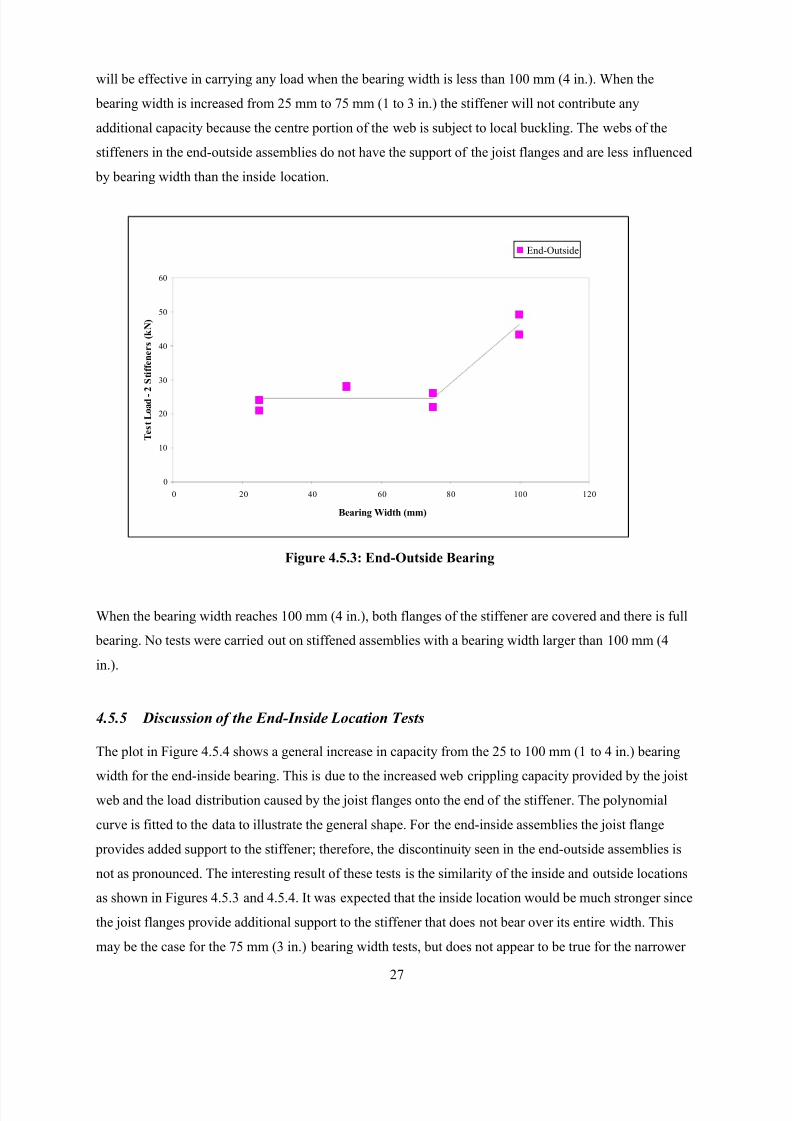
8/2/2019 Design of Bearing Stiffeners in Cold Formed C-Sections
http://slidepdf.com/reader/full/design-of-bearing-stiffeners-in-cold-formed-c-sections 41/151
27
will be effective in carrying any load when the bearing width is less than 100 mm (4 in.). When the
bearing width is increased from 25 mm to 75 mm (1 to 3 in.) the stiffener will not contribute any
additional capacity because the centre portion of the web is subject to local buckling. The webs of the
stiffeners in the end-outside assemblies do not have the support of the joist flanges and are less influenced
by bearing width than the inside location.
When the bearing width reaches 100 mm (4 in.), both flanges of the stiffener are covered and there is full
bearing. No tests were carried out on stiffened assemblies with a bearing width larger than 100 mm (4
in.).
4.5.5 Discussion of the End-Inside Location Tests
The plot in Figure 4.5.4 shows a general increase in capacity from the 25 to 100 mm (1 to 4 in.) bearing
width for the end-inside bearing. This is due to the increased web crippling capacity provided by the joist
web and the load distribution caused by the joist flanges onto the end of the stiffener. The polynomial
curve is fitted to the data to illustrate the general shape. For the end-inside assemblies the joist flange
provides added support to the stiffener; therefore, the discontinuity seen in the end-outside assemblies is
not as pronounced. The interesting result of these tests is the similarity of the inside and outside locations
as shown in Figures 4.5.3 and 4.5.4. It was expected that the inside location would be much stronger since
the joist flanges provide additional support to the stiffener that does not bear over its entire width. This
may be the case for the 75 mm (3 in.) bearing width tests, but does not appear to be true for the narrower
Figure 4.5.3: End-Outside Bearing
0
10
20
30
40
50
60
0 20 40 60 80 100 120
Bearing Width (mm)
T e s t L o a d - 2 S t i f f e n e r s ( k N )
End-Outside
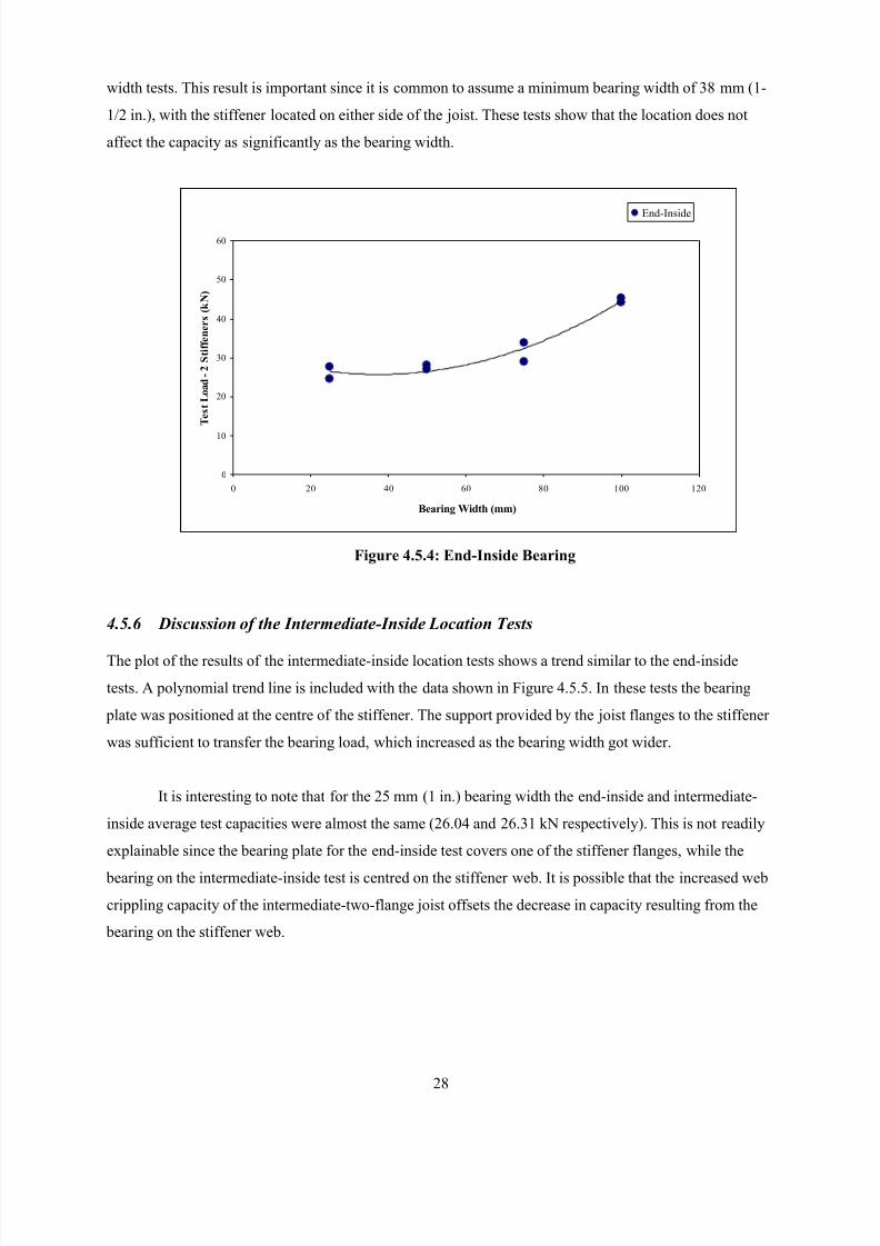
8/2/2019 Design of Bearing Stiffeners in Cold Formed C-Sections
http://slidepdf.com/reader/full/design-of-bearing-stiffeners-in-cold-formed-c-sections 42/151
28
width tests. This result is important since it is common to assume a minimum bearing width of 38 mm (1-
1/2 in.), with the stiffener located on either side of the joist. These tests show that the location does not
affect the capacity as significantly as the bearing width.
4.5.6 Discussion of the Intermediate-Inside Location Tests
The plot of the results of the intermediate-inside location tests shows a trend similar to the end-inside
tests. A polynomial trend line is included with the data shown in Figure 4.5.5. In these tests the bearing
plate was positioned at the centre of the stiffener. The support provided by the joist flanges to the stiffener
was sufficient to transfer the bearing load, which increased as the bearing width got wider.
It is interesting to note that for the 25 mm (1 in.) bearing width the end-inside and intermediate-
inside average test capacities were almost the same (26.04 and 26.31 kN respectively). This is not readily
explainable since the bearing plate for the end-inside test covers one of the stiffener flanges, while the
bearing on the intermediate-inside test is centred on the stiffener web. It is possible that the increased web
crippling capacity of the intermediate-two-flange joist offsets the decrease in capacity resulting from the
bearing on the stiffener web.
Figure 4.5.4: End-Inside Bearing
0
10
20
30
40
50
60
0 20 40 60 80 100 120
Bearing Width (mm)
T e s t L o a d - 2 S t i f f e n e r s ( k N )
End-Inside
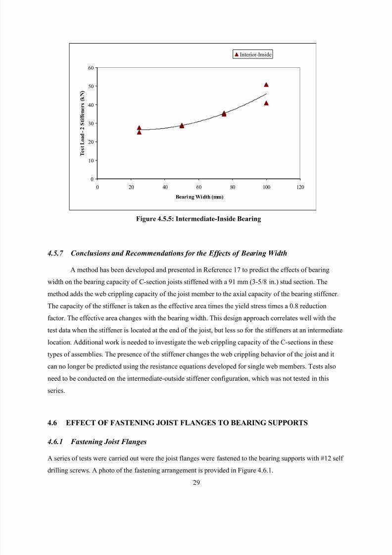
8/2/2019 Design of Bearing Stiffeners in Cold Formed C-Sections
http://slidepdf.com/reader/full/design-of-bearing-stiffeners-in-cold-formed-c-sections 43/151
29
4.5.7 Conclusions and Recommendations for the Effects of Bearing Width
A method has been developed and presented in Reference 17 to predict the effects of bearing
width on the bearing capacity of C-section joists stiffened with a 91 mm (3-5/8 in.) stud section. The
method adds the web crippling capacity of the joist member to the axial capacity of the bearing stiffener.
The capacity of the stiffener is taken as the effective area times the yield stress times a 0.8 reduction
factor. The effective area changes with the bearing width. This design approach correlates well with the
test data when the stiffener is located at the end of the joist, but less so for the stiffeners at an intermediate
location. Additional work is needed to investigate the web crippling capacity of the C-sections in these
types of assemblies. The presence of the stiffener changes the web crippling behavior of the joist and it
can no longer be predicted using the resistance equations developed for single web members. Tests also
need to be conducted on the intermediate-outside stiffener configuration, which was not tested in this
series.
4.6 EFFECT OF FASTENING JOIST FLANGES TO BEARING SUPPORTS
4.6.1 Fastening Joist Flanges
A series of tests were carried out were the joist flanges were fastened to the bearing supports with #12 self
drilling screws. A photo of the fastening arrangement is provided in Figure 4.6.1.
Figure 4.5.5: Intermediate-Inside Bearing
0
10
20
30
40
50
60
0 20 40 60 80 100 120
Bearing Width (mm)
T e s t L o a d - 2 S t i f f e n e r s ( k N )
Interior-Inside
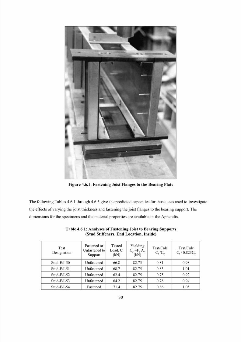
8/2/2019 Design of Bearing Stiffeners in Cold Formed C-Sections
http://slidepdf.com/reader/full/design-of-bearing-stiffeners-in-cold-formed-c-sections 44/151
30
Figure 4.6.1: Fastening Joist Flanges to the Bearing Plate
The following Tables 4.6.1 through 4.6.5 give the predicted capacities for those tests used to investigate
the effects of varying the joist thickness and fastening the joist flanges to the bearing support. The
dimensions for the specimens and the material properties are available in the Appendix.
Table 4.6.1: Analyses of Fastening Joist to Bearing Supports
(Stud Stiffeners, End Location, Inside)
Test
Designation
Fastened or
Unfastened to
Support
Tested
Load, Ct
(kN)
Yielding
Cy =Fy Ae
(kN)
Test/Calc
Ct /Cy
Test/Calc
Ct / 0.823Cy
Stud-E/I-50 Unfastened 66.8 82.75 0.81 0.98
Stud-E/I-51 Unfastened 68.7 82.75 0.83 1.01
Stud-E/I-52 Unfastened 62.4 82.75 0.75 0.92
Stud-E/I-53 Unfastened 64.2 82.75 0.78 0.94
Stud-E/I-54 Fastened 71.4 82.75 0.86 1.05
8/2/2019 Design of Bearing Stiffeners in Cold Formed C-Sections
http://slidepdf.com/reader/full/design-of-bearing-stiffeners-in-cold-formed-c-sections 45/151
31
Stud-E/I-55 Fastened 70.2 82.75 0.85 1.03
Stud-E/I-56 Fastened 74.9 83.17 0.90 1.09
Stud-E/I-57 Fastened 71.6 82.75 0.86 1.05
Stud-E/I-58 Unfastened 65.90 82.75 0.80 0.97
Stud-E/I-59 Unfastened 64.80 83.59 0.78 0.94
Stud-E/I-60 Fastened 71.40 83.17 0.86 1.04
Stud-E/I-61 Fastened 67.40 83.59 0.81 0.98
Average 0.823 1.00
COV 0.054
Average for Unfastened 65.46 0.96
COV 0.033 0.034
Average for Fastened 71.13 1.04
COV 0.034 0.035
Note: Calculated values are for 2 stiffeners. 1 kN = 224.8 lbs, 1 mm = 0.0394 in.
Table 4.6.2: Analyses of Fastening Joist to Bearing Supports
(Stud Stiffeners, End Location, Outside)
TestDesignation
Fastened or
Unfastened to
Support
Tested
Load, Ct
(kN)
Yielding
Cy =Fy Ae
(kN)
Test/CalcCt /Cy
Test/CalcCt / 0.940Cy
Stud-E/O-13 Unfastened 82.8 82.75 1.00 1.06
Stud-E/O-14 Unfastened 86.1 82.75 1.04 1.11
Stud-E/O-15 Unfastened 70.1 83.59 0.84 0.89
Stud-E/O-16 Unfastened 82.8 83.59 0.99 1.05
Stud-E/O-17 Fastened 81.9 82.75 0.99 1.05
Stud-E/O-18 Fastened 75.2 82.75 0.91 0.97
Stud-E/O-19 Fastened 69.2 83.59 0.83 0.88
Stud-E/O-20 Unfastened 76.50 82.75 0.92 0.98
Stud-E/O-21 Unfastened 78.50 83.59 0.94 1.00
Average 0.940 1.00
COV 0.078
Average for Unfastened 79.46 1.02
COV 0.072 0.075
Average for Fastened 75.40 0.97
COV 0.085 0.089
Note: Calculated values are for 2 stiffeners. 1 kN = 224.8 lbs, 1 mm = 0.0394 in.
Table 4.6.3: Analyses of Fastening Joist to Bearing Supports
(Stud Stiffeners, Intermediate Location, Inside)
Test
Designation
Fastened or
Unfastened toSupport
Tested
Load, Ct
(kN)
Yielding
Cy =Fy Ae
(kN)
Test/Calc
Ct /Cy
Test/Calc
Ct / 1.098Cy
Stud-I/I-11 Unfastened 79.1 82.75 0.96 0.87
Stud-I/I-12 Unfastened 95.7 82.75 1.16 1.05
8/2/2019 Design of Bearing Stiffeners in Cold Formed C-Sections
http://slidepdf.com/reader/full/design-of-bearing-stiffeners-in-cold-formed-c-sections 46/151
32
Stud-I/I-13 Fastened 97.1 82.75 1.17 1.07
Stud-I/I-14 Fastened 91.5 82.75 1.11 1.01
Average 1.098 1.00
COV 0.090
Average for Unfastened 87.38 0.96
COV 0.135 0.135
Average for Fastened 94.28 1.04
COV 0.042 0.042
Note: Calculated values are for 2 stiffeners. 1 kN = 224.8 lbs, 1 mm = 0.0394 in.
Table 4.6.4: Analyses of Fastening Joist to Bearing Supports
(Stud Stiffeners, Intermediate Location, Outside)
Test
Designation
Fastened or
Unfastened to
Support
Tested
Load, Ct
(kN)
Yielding
Cy =Fy Ae
(kN)
Test/Calc
Ct /Cy
Test/Calc
Ct / 0.999Cy
Stud-I/O-5 Unfastened 79.2 82.75 0.96 0.96
Stud-I/O-6 Unfastened 75.9 82.75 0.92 0.92
Stud-I/O-7 Unfastened 83.9 83.59 1.00 1.00
Stud-I/O-8 Unfastened 79.2 83.59 0.95 0.95
Stud-I/O-9 Fastened 77.3 82.75 0.93 0.93
Stud-I/O-10 Fastened 79.5 82.75 0.96 0.96
Stud-I/O-11 Fastened 87.9 83.59 1.05 1.05
Stud-I/O-12 Fastened 87.8 83.59 1.05 1.05
Stud-I/O-13 Unfastened 89.9 83.59 1.08 1.08
Stud-I/O-14 Unfastened 91.1 83.59 1.09 1.09
Average 0.999 1.00
COV 0.064
Average for Unfastened 83.19 1.00
COV 0.075 0.036
Average for Fastened 83.10 1.00
COV 0.067 0.061
Note: Calculated values are for 2 stiffeners. 1 kN = 224.8 lbs, 1 mm = 0.0394 in.
Table 4.6.5: Analyses of Fastening Joist to Bearing Supports
(Track Stiffeners, Intermediate Location, Inside)
TestDesignation
Fastened or
Unfastened to
Support
Tested
Load, Ct
(kN)
Yielding
Cy =Fy Ae
(kN)
Test/CalcCt /Cy
Test/CalcCt / 1.038Cy
Track-I/I-1 Unfastened 66.3 67.02 0.99 0.95
Track-I/I-2 Unfastened 74.85 67.02 1.12 1.08
Track-I/I-3 Fastened 62.55 67.07 0.93 0.90
Track-I/I-4 Fastened 73.65 67.07 1.10 1.06
Track-I/I-5 Unfastened 69.2 67.04 1.03 0.99
8/2/2019 Design of Bearing Stiffeners in Cold Formed C-Sections
http://slidepdf.com/reader/full/design-of-bearing-stiffeners-in-cold-formed-c-sections 47/151
33
Track-I/I-6 Unfastened 66.5 67.02 0.99 0.96
Track-I/I-7 Fastened 71.9 67.02 1.07 1.03
Track-I/I-8 Fastened 71.9 67.02 1.07 1.03
Average 1.038 1.00
COV 0.061 0.061
Average for Unfastened 69.21 0.99
COV 0.058 0.058
Average for Fastened 70.00 1.01
COV 0.072 0.072
Note: Calculated values are for 2 stiffeners. 1 kN = 224.8 lbs, 1 mm = 0.0394 in.
4.6.2 Effect of Fastening the Joist to the Support
Investigations into web crippling [9] have shown that fastening the joist flanges to the bearing supports
can have a measurable impact on the web crippling capacity, particularly for Z-sections and multiple web
sections. For C-section, the impact is not as significant. Testing of unreinforced C-sections has shown thatfastening the flanges to the supports generally increases the capacity, but not more than 10%. This
behavior was also observed for the C-sections with bearing stiffeners, as summarized in Table 4.6.6.
Table 4.6.6: Comparison of Fastened and Unfastened Test Results
Test ConfigurationReduction
FactorDifference
Unfastened 0.96Stud Stiffeners, End Location, Inside
Fastened 1.04+ 8%
Unfastened 1.02Stud Stiffeners, End Location, Outside
Fastened 0.97
- 5%
Unfastened 0.96Stud Stiffeners, Intermediate Location, Inside
Fastened 1.04+ 8%
Unfastened 1.00Stud Stiffeners, Intermediate Location, Outside
Fastened 1.000
Unfastened 0.99Track Stiffeners, Intermediate Location, Inside
Fastened 1.01+ 2%
The results shown in Table 4.6.6 could support the theory that the capacity of a C-section with bearing
stiffeners is a combination of both the web crippling capacity of the joist as well as the bearing capacity
of the stiffener. If the bearing stiffener was carrying all of the load at the ultimate limit state, there should
be no significant difference between the fastened and unfastened assemblies. Since tests show a
difference, some load is being carried by the joist web. It could also be argued, however, that the results
in Table 4.6.6 can be explained by experimental error.
The load carried by the joist is a function of the location of the bearing stiffener. When the stiffener is on
the back of the joist, the load is transferred into the stiffener directly and immediately. Since the bearing
stiffener subject to axial compression is much stiffer than the C-section subject to a two-flange-loading,

8/2/2019 Design of Bearing Stiffeners in Cold Formed C-Sections
http://slidepdf.com/reader/full/design-of-bearing-stiffeners-in-cold-formed-c-sections 48/151
34
the majority of the load will be carried by the stiffener. This assumption appears to be borne out by results
shown in Table 4.6.6. There is little or no effect of fastening the flanges when the stiffener is on the
outside of the joist.
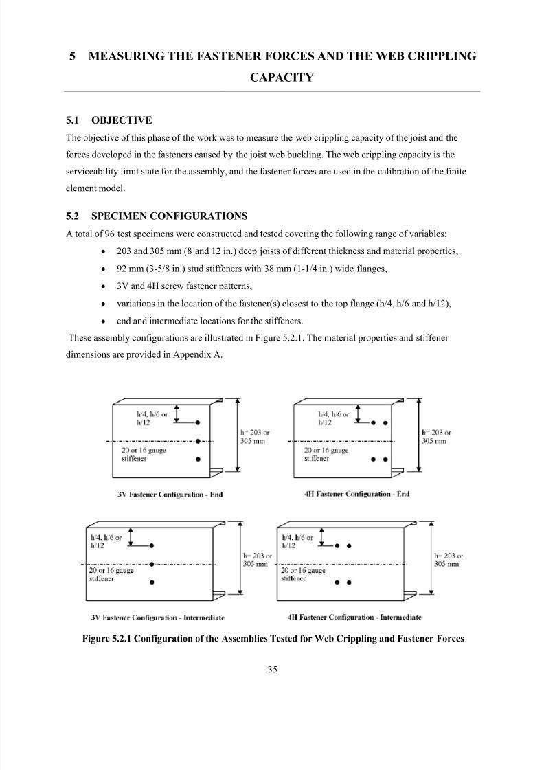
8/2/2019 Design of Bearing Stiffeners in Cold Formed C-Sections
http://slidepdf.com/reader/full/design-of-bearing-stiffeners-in-cold-formed-c-sections 49/151
35
5 MEASURING THE FASTENER FORCES AND THE WEB CRIPPLING
CAPACITY
5.1 OBJECTIVE
The objective of this phase of the work was to measure the web crippling capacity of the joist and the
forces developed in the fasteners caused by the joist web buckling. The web crippling capacity is the
serviceability limit state for the assembly, and the fastener forces are used in the calibration of the finite
element model.
5.2 SPECIMEN CONFIGURATIONS
A total of 96 test specimens were constructed and tested covering the following range of variables:
• 203 and 305 mm (8 and 12 in.) deep joists of different thickness and material properties,
• 92 mm (3-5/8 in.) stud stiffeners with 38 mm (1-1/4 in.) wide flanges,
• 3V and 4H screw fastener patterns,
• variations in the location of the fastener(s) closest to the top flange (h/4, h/6 and h/12),
• end and intermediate locations for the stiffeners.
These assembly configurations are illustrated in Figure 5.2.1. The material properties and stiffener
dimensions are provided in Appendix A.
Figure 5.2.1 Configuration of the Assemblies Tested for Web Crippling and Fastener Forces
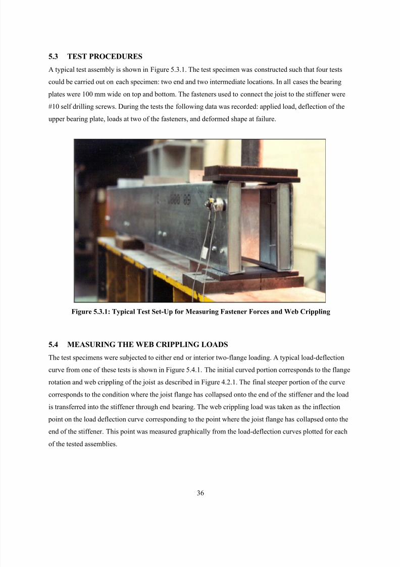
8/2/2019 Design of Bearing Stiffeners in Cold Formed C-Sections
http://slidepdf.com/reader/full/design-of-bearing-stiffeners-in-cold-formed-c-sections 50/151
36
5.3 TEST PROCEDURES
A typical test assembly is shown in Figure 5.3.1. The test specimen was constructed such that four tests
could be carried out on each specimen: two end and two intermediate locations. In all cases the bearing
plates were 100 mm wide on top and bottom. The fasteners used to connect the joist to the stiffener were
#10 self drilling screws. During the tests the following data was recorded: applied load, deflection of the
upper bearing plate, loads at two of the fasteners, and deformed shape at failure.
Figure 5.3.1: Typical Test Set-Up for Measuring Fastener Forces and Web Crippling
5.4 MEASURING THE WEB CRIPPLING LOADS
The test specimens were subjected to either end or interior two-flange loading. A typical load-deflection
curve from one of these tests is shown in Figure 5.4.1. The initial curved portion corresponds to the flange
rotation and web crippling of the joist as described in Figure 4.2.1. The final steeper portion of the curve
corresponds to the condition where the joist flange has collapsed onto the end of the stiffener and the loadis transferred into the stiffener through end bearing. The web crippling load was taken as the inflection
point on the load deflection curve corresponding to the point where the joist flange has collapsed onto the
end of the stiffener. This point was measured graphically from the load-deflection curves plotted for each
of the tested assemblies.
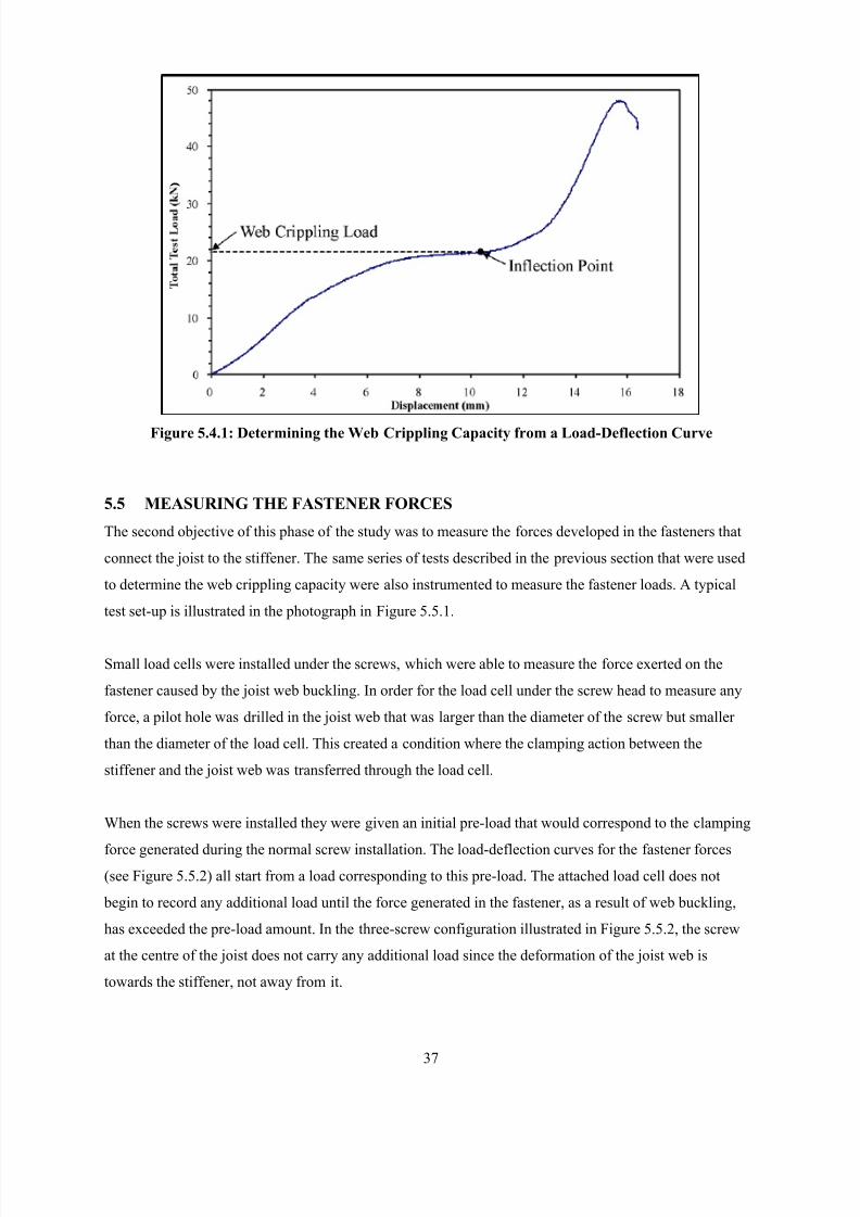
8/2/2019 Design of Bearing Stiffeners in Cold Formed C-Sections
http://slidepdf.com/reader/full/design-of-bearing-stiffeners-in-cold-formed-c-sections 51/151
37
Figure 5.4.1: Determining the Web Crippling Capacity from a Load-Deflection Curve
5.5 MEASURING THE FASTENER FORCES
The second objective of this phase of the study was to measure the forces developed in the fasteners that
connect the joist to the stiffener. The same series of tests described in the previous section that were used
to determine the web crippling capacity were also instrumented to measure the fastener loads. A typical
test set-up is illustrated in the photograph in Figure 5.5.1.
Small load cells were installed under the screws, which were able to measure the force exerted on the
fastener caused by the joist web buckling. In order for the load cell under the screw head to measure any
force, a pilot hole was drilled in the joist web that was larger than the diameter of the screw but smaller
than the diameter of the load cell. This created a condition where the clamping action between the
stiffener and the joist web was transferred through the load cell.
When the screws were installed they were given an initial pre-load that would correspond to the clamping
force generated during the normal screw installation. The load-deflection curves for the fastener forces(see Figure 5.5.2) all start from a load corresponding to this pre-load. The attached load cell does not
begin to record any additional load until the force generated in the fastener, as a result of web buckling,
has exceeded the pre-load amount. In the three-screw configuration illustrated in Figure 5.5.2, the screw
at the centre of the joist does not carry any additional load since the deformation of the joist web is
towards the stiffener, not away from it.
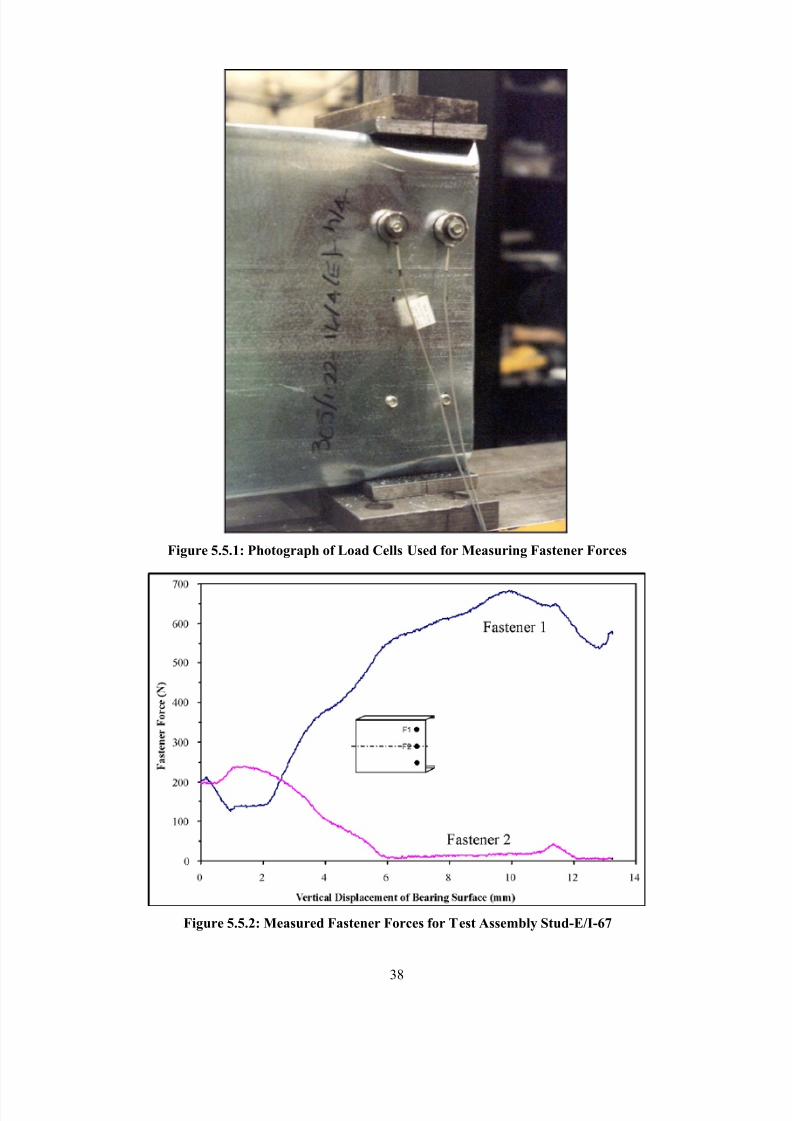
8/2/2019 Design of Bearing Stiffeners in Cold Formed C-Sections
http://slidepdf.com/reader/full/design-of-bearing-stiffeners-in-cold-formed-c-sections 52/151
38
Figure 5.5.1: Photograph of Load Cells Used for Measuring Fastener Forces
Figure 5.5.2: Measured Fastener Forces for Test Assembly Stud-E/I-67
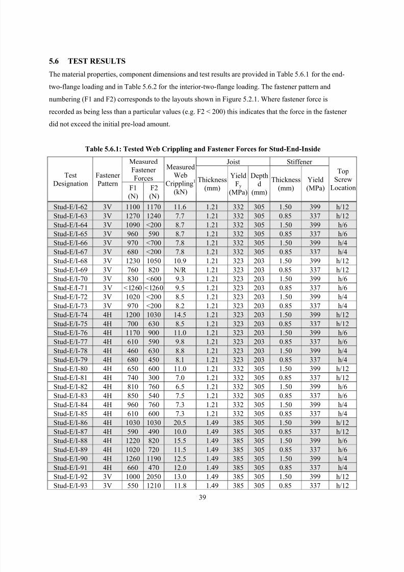
8/2/2019 Design of Bearing Stiffeners in Cold Formed C-Sections
http://slidepdf.com/reader/full/design-of-bearing-stiffeners-in-cold-formed-c-sections 53/151
39
5.6 TEST RESULTS
The material properties, component dimensions and test results are provided in Table 5.6.1 for the end-
two-flange loading and in Table 5.6.2 for the interior-two-flange loading. The fastener pattern and
numbering (F1 and F2) corresponds to the layouts shown in Figure 5.2.1. Where fastener force is
recorded as being less than a particular values (e.g. F2 < 200) this indicates that the force in the fastener
did not exceed the initial pre-load amount.
Table 5.6.1: Tested Web Crippling and Fastener Forces for Stud-End-Inside
Joist Stiffener Measured
Fastener
ForcesTest
Designation
Fastener
PatternF1
(N)
F2
(N)
Measured
Web
Crippling1
(kN)
Thickness
(mm)
Yield
Fy
(MPa)
Depth
d
(mm)
Thickness
(mm)
Yield
(MPa)
Top
Screw
Location
Stud-E/I-62 3V 1100 1170 11.6 1.21 332 305 1.50 399 h/12
Stud-E/I-63 3V 1270 1240 7.7 1.21 332 305 0.85 337 h/12
Stud-E/I-64 3V 1090 <200 8.7 1.21 332 305 1.50 399 h/6
Stud-E/I-65 3V 960 590 8.7 1.21 332 305 0.85 337 h/6
Stud-E/I-66 3V 970 <700 7.8 1.21 332 305 1.50 399 h/4
Stud-E/I-67 3V 680 <200 7.8 1.21 332 305 0.85 337 h/4
Stud-E/I-68 3V 1230 1050 10.9 1.21 323 203 1.50 399 h/12
Stud-E/I-69 3V 760 820 N/R 1.21 323 203 0.85 337 h/12
Stud-E/I-70 3V 830 <600 9.3 1.21 323 203 1.50 399 h/6
Stud-E/I-71 3V <1260 <1260 9.5 1.21 323 203 0.85 337 h/6
Stud-E/I-72 3V 1020 <200 8.5 1.21 323 203 1.50 399 h/4Stud-E/I-73 3V 970 <200 8.2 1.21 323 203 0.85 337 h/4
Stud-E/I-74 4H 1200 1030 14.5 1.21 323 203 1.50 399 h/12
Stud-E/I-75 4H 700 630 8.5 1.21 323 203 0.85 337 h/12
Stud-E/I-76 4H 1170 900 11.0 1.21 323 203 1.50 399 h/6
Stud-E/I-77 4H 610 590 9.8 1.21 323 203 0.85 337 h/6
Stud-E/I-78 4H 460 630 8.8 1.21 323 203 1.50 399 h/4
Stud-E/I-79 4H 680 450 8.1 1.21 323 203 0.85 337 h/4
Stud-E/I-80 4H 650 600 11.0 1.21 332 305 1.50 399 h/12
Stud-E/I-81 4H 740 300 7.0 1.21 332 305 0.85 337 h/12
Stud-E/I-82 4H 810 760 6.5 1.21 332 305 1.50 399 h/6
Stud-E/I-83 4H 850 540 7.5 1.21 332 305 0.85 337 h/6
Stud-E/I-84 4H 960 760 7.3 1.21 332 305 1.50 399 h/4
Stud-E/I-85 4H 610 600 7.3 1.21 332 305 0.85 337 h/4
Stud-E/I-86 4H 1030 1030 20.5 1.49 385 305 1.50 399 h/12
Stud-E/I-87 4H 590 490 10.0 1.49 385 305 0.85 337 h/12
Stud-E/I-88 4H 1220 820 15.5 1.49 385 305 1.50 399 h/6
Stud-E/I-89 4H 1020 720 11.5 1.49 385 305 0.85 337 h/6
Stud-E/I-90 4H 1260 1190 12.5 1.49 385 305 1.50 399 h/4
Stud-E/I-91 4H 660 470 12.0 1.49 385 305 0.85 337 h/4
Stud-E/I-92 3V 1000 2050 13.0 1.49 385 305 1.50 399 h/12
Stud-E/I-93 3V 550 1210 11.8 1.49 385 305 0.85 337 h/12
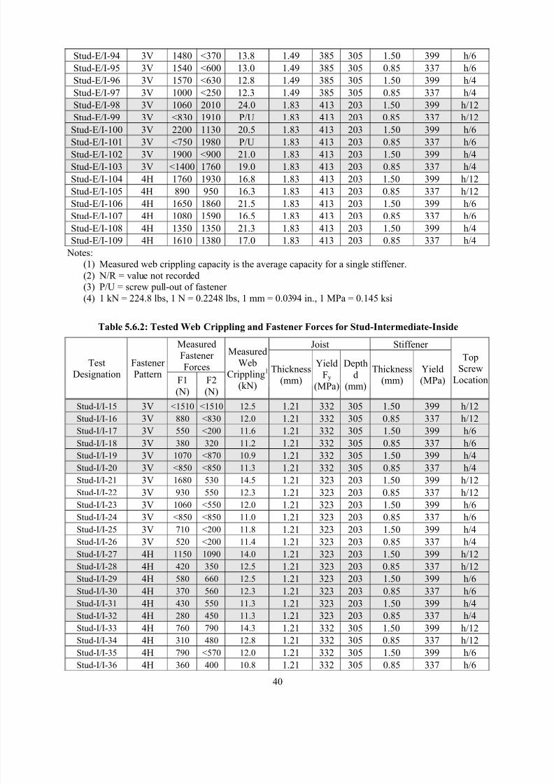
8/2/2019 Design of Bearing Stiffeners in Cold Formed C-Sections
http://slidepdf.com/reader/full/design-of-bearing-stiffeners-in-cold-formed-c-sections 54/151
40
Stud-E/I-94 3V 1480 <370 13.8 1.49 385 305 1.50 399 h/6
Stud-E/I-95 3V 1540 <600 13.0 1.49 385 305 0.85 337 h/6
Stud-E/I-96 3V 1570 <630 12.8 1.49 385 305 1.50 399 h/4
Stud-E/I-97 3V 1000 <250 12.3 1.49 385 305 0.85 337 h/4
Stud-E/I-98 3V 1060 2010 24.0 1.83 413 203 1.50 399 h/12
Stud-E/I-99 3V <830 1910 P/U 1.83 413 203 0.85 337 h/12
Stud-E/I-100 3V 2200 1130 20.5 1.83 413 203 1.50 399 h/6
Stud-E/I-101 3V <750 1980 P/U 1.83 413 203 0.85 337 h/6
Stud-E/I-102 3V 1900 <900 21.0 1.83 413 203 1.50 399 h/4
Stud-E/I-103 3V <1400 1760 19.0 1.83 413 203 0.85 337 h/4
Stud-E/I-104 4H 1760 1930 16.8 1.83 413 203 1.50 399 h/12
Stud-E/I-105 4H 890 950 16.3 1.83 413 203 0.85 337 h/12
Stud-E/I-106 4H 1650 1860 21.5 1.83 413 203 1.50 399 h/6
Stud-E/I-107 4H 1080 1590 16.5 1.83 413 203 0.85 337 h/6
Stud-E/I-108 4H 1350 1350 21.3 1.83 413 203 1.50 399 h/4
Stud-E/I-109 4H 1610 1380 17.0 1.83 413 203 0.85 337 h/4
Notes:
(1) Measured web crippling capacity is the average capacity for a single stiffener.
(2) N/R = value not recorded(3) P/U = screw pull-out of fastener
(4) 1 kN = 224.8 lbs, 1 N = 0.2248 lbs, 1 mm = 0.0394 in., 1 MPa = 0.145 ksi
Table 5.6.2: Tested Web Crippling and Fastener Forces for Stud-Intermediate-Inside
Joist Stiffener Measured
Fastener
ForcesTest
Designation
Fastener
PatternF1
(N)
F2
(N)
Measured
Web
Crippling1
(kN)
Thickness
(mm)
Yield
Fy
(MPa)
Depth
d
(mm)
Thickness
(mm)
Yield
(MPa)
Top
Screw
Location
Stud-I/I-15 3V <1510 <1510 12.5 1.21 332 305 1.50 399 h/12
Stud-I/I-16 3V 880 <830 12.0 1.21 332 305 0.85 337 h/12
Stud-I/I-17 3V 550 <200 11.6 1.21 332 305 1.50 399 h/6
Stud-I/I-18 3V 380 320 11.2 1.21 332 305 0.85 337 h/6
Stud-I/I-19 3V 1070 <870 10.9 1.21 332 305 1.50 399 h/4
Stud-I/I-20 3V <850 <850 11.3 1.21 332 305 0.85 337 h/4
Stud-I/I-21 3V 1680 530 14.5 1.21 323 203 1.50 399 h/12
Stud-I/I-22 3V 930 550 12.3 1.21 323 203 0.85 337 h/12
Stud-I/I-23 3V 1060 <550 12.0 1.21 323 203 1.50 399 h/6
Stud-I/I-24 3V <850 <850 11.0 1.21 323 203 0.85 337 h/6
Stud-I/I-25 3V 710 <200 11.8 1.21 323 203 1.50 399 h/4
Stud-I/I-26 3V 520 <200 11.4 1.21 323 203 0.85 337 h/4
Stud-I/I-27 4H 1150 1090 14.0 1.21 323 203 1.50 399 h/12
Stud-I/I-28 4H 420 350 12.5 1.21 323 203 0.85 337 h/12
Stud-I/I-29 4H 580 660 12.5 1.21 323 203 1.50 399 h/6
Stud-I/I-30 4H 370 560 12.3 1.21 323 203 0.85 337 h/6
Stud-I/I-31 4H 430 550 11.3 1.21 323 203 1.50 399 h/4
Stud-I/I-32 4H 280 450 11.3 1.21 323 203 0.85 337 h/4
Stud-I/I-33 4H 760 790 14.3 1.21 332 305 1.50 399 h/12
Stud-I/I-34 4H 310 480 12.8 1.21 332 305 0.85 337 h/12
Stud-I/I-35 4H 790 <570 12.0 1.21 332 305 1.50 399 h/6
Stud-I/I-36 4H 360 400 10.8 1.21 332 305 0.85 337 h/6
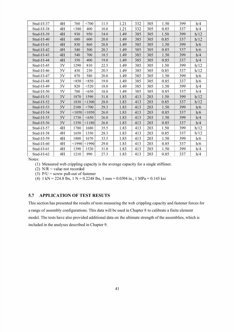
8/2/2019 Design of Bearing Stiffeners in Cold Formed C-Sections
http://slidepdf.com/reader/full/design-of-bearing-stiffeners-in-cold-formed-c-sections 55/151
41
Stud-I/I-37 4H 760 <700 11.5 1.21 332 305 1.50 399 h/4
Stud-I/I-38 4H <380 400 10.8 1.21 332 305 0.85 337 h/4
Stud-I/I-39 4H 930 950 24.0 1.49 385 305 1.50 399 h/12
Stud-I/I-40 4H 680 600 20.0 1.49 385 305 0.85 337 h/12
Stud-I/I-41 4H 830 860 20.8 1.49 385 305 1.50 399 h/6
Stud-I/I-42 4H 540 500 20.3 1.49 385 305 0.85 337 h/6
Stud-I/I-43 4H 540 700 18.5 1.49 385 305 1.50 399 h/4
Stud-I/I-44 4H 350 400 19.0 1.49 385 305 0.85 337 h/4
Stud-I/I-45 3V 1290 810 22.5 1.49 385 305 1.50 399 h/12
Stud-I/I-46 3V 430 230 20.5 1.49 385 305 0.85 337 h/12
Stud-I/I-47 3V 870 580 20.0 1.49 385 305 1.50 399 h/6
Stud-I/I-48 3V <850 <850 19.0 1.49 385 305 0.85 337 h/6
Stud-I/I-49 3V 820 <520 18.8 1.49 385 305 1.50 399 h/4
Stud-I/I-50 3V 700 <650 18.8 1.49 385 305 0.85 337 h/4
Stud-I/I-51 3V 1870 1590 31.8 1.83 413 203 1.50 399 h/12
Stud-I/I-52 3V 1830 <1300 28.0 1.83 413 203 0.85 337 h/12
Stud-I/I-53 3V 2100 <700 29.3 1.83 413 203 1.50 399 h/6
Stud-I/I-54 3V <1050 <1050 26.0 1.83 413 203 0.85 337 h/6
Stud-I/I-55 3V 1730 <650 26.8 1.83 413 203 1.50 399 h/4
Stud-I/I-56 3V 1350 <1180 26.8 1.83 413 203 0.85 337 h/4
Stud-I/I-57 4H 1780 1680 35.5 1.83 413 203 1.50 399 h/12
Stud-I/I-58 4H 1650 1350 28.3 1.83 413 203 0.85 337 h/12
Stud-I/I-59 4H 1800 1670 33.5 1.83 413 203 1.50 399 h/6
Stud-I/I-60 4H <1990 <1990 29.0 1.83 413 203 0.85 337 h/6
Stud-I/I-61 4H 1390 1520 31.0 1.83 413 203 1.50 399 h/4
Stud-I/I-62 4H 1210 990 27.3 1.83 413 203 0.85 337 h/4
Notes:
(1) Measured web crippling capacity is the average capacity for a single stiffener.
(2) N/R = value not recorded
(3) P/U = screw pull-out of fastener (4) 1 kN = 224.8 lbs, 1 N = 0.2248 lbs, 1 mm = 0.0394 in., 1 MPa = 0.145 ksi
5.7 APPLICATION OF TEST RESUTS
This section has presented the results of tests measuring the web crippling capacity and fastener forces for
a range of assembly configurations. This data will be used in Chapter 8 to calibrate a finite element
model. The tests have also provided additional data on the ultimate strength of the assemblies, which is
included in the analyses described in Chapter 9.
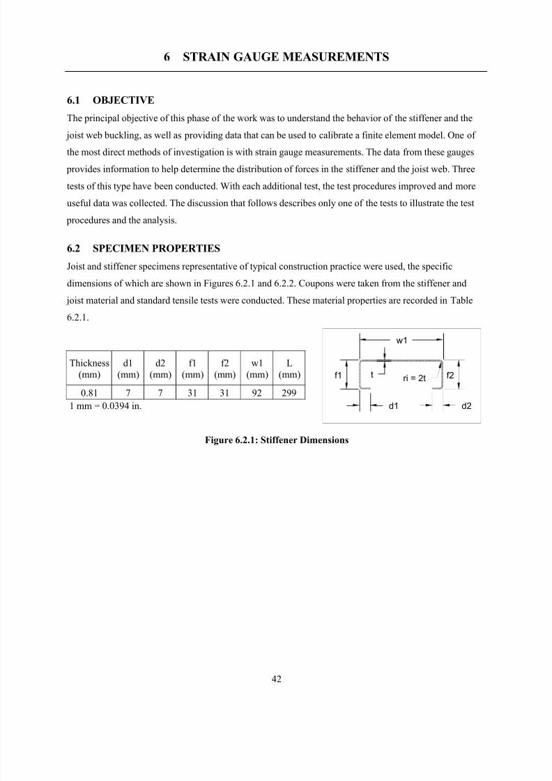
8/2/2019 Design of Bearing Stiffeners in Cold Formed C-Sections
http://slidepdf.com/reader/full/design-of-bearing-stiffeners-in-cold-formed-c-sections 56/151
42
6 STRAIN GAUGE MEASUREMENTS
6.1 OBJECTIVE
The principal objective of this phase of the work was to understand the behavior of the stiffener and the
joist web buckling, as well as providing data that can be used to calibrate a finite element model. One of
the most direct methods of investigation is with strain gauge measurements. The data from these gauges
provides information to help determine the distribution of forces in the stiffener and the joist web. Three
tests of this type have been conducted. With each additional test, the test procedures improved and more
useful data was collected. The discussion that follows describes only one of the tests to illustrate the test
procedures and the analysis.
6.2 SPECIMEN PROPERTIES
Joist and stiffener specimens representative of typical construction practice were used, the specific
dimensions of which are shown in Figures 6.2.1 and 6.2.2. Coupons were taken from the stiffener and
joist material and standard tensile tests were conducted. These material properties are recorded in Table
6.2.1.
Thickness
(mm)
d1
(mm)
d2
(mm)
f1
(mm)
f2
(mm)
w1
(mm)
L
(mm)
0.81 7 7 31 31 92 299
1 mm = 0.0394 in.
Figure 6.2.1: Stiffener Dimensions
f2ri = 2t
d2d1
f1 t
w1
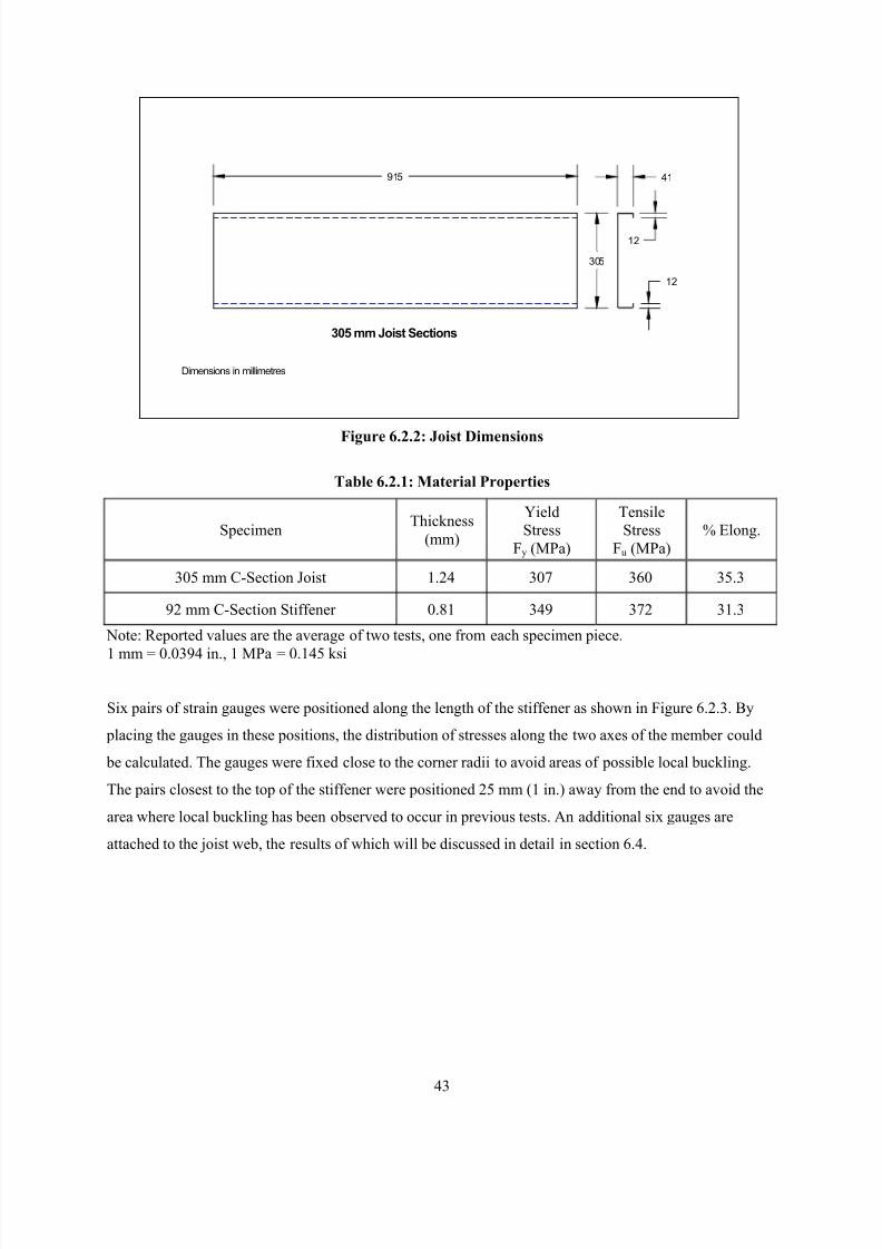
8/2/2019 Design of Bearing Stiffeners in Cold Formed C-Sections
http://slidepdf.com/reader/full/design-of-bearing-stiffeners-in-cold-formed-c-sections 57/151
43
12
41
12
305
915
305 mm Joist Sections
Dimensions in millimetres
Figure 6.2.2: Joist Dimensions
Table 6.2.1: Material Properties
SpecimenThickness
(mm)
Yield
Stress
Fy (MPa)
Tensile
Stress
Fu (MPa)
% Elong.
305 mm C-Section Joist 1.24 307 360 35.3
92 mm C-Section Stiffener 0.81 349 372 31.3
Note: Reported values are the average of two tests, one from each specimen piece.
1 mm = 0.0394 in., 1 MPa = 0.145 ksi
Six pairs of strain gauges were positioned along the length of the stiffener as shown in Figure 6.2.3. By
placing the gauges in these positions, the distribution of stresses along the two axes of the member could
be calculated. The gauges were fixed close to the corner radii to avoid areas of possible local buckling.
The pairs closest to the top of the stiffener were positioned 25 mm (1 in.) away from the end to avoid the
area where local buckling has been observed to occur in previous tests. An additional six gauges are
attached to the joist web, the results of which will be discussed in detail in section 6.4.
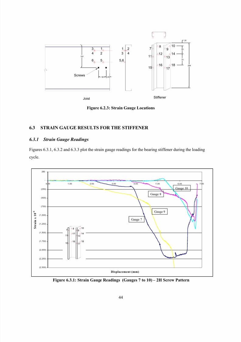
8/2/2019 Design of Bearing Stiffeners in Cold Formed C-Sections
http://slidepdf.com/reader/full/design-of-bearing-stiffeners-in-cold-formed-c-sections 58/151
44
Figure 6.2.3: Strain Gauge Locations
6.3 STRAIN GAUGE RESULTS FOR THE STIFFENER
6.3.1 Strain Gauge Readings
Figures 6.3.1, 6.3.2 and 6.3.3 plot the strain gauge readings for the bearing stiffener during the loading
cycle.
Figure 6.3.1: Strain Gauge Readings (Gauges 7 to 10) – 2H Screw Pattern
(2,500)
(2,250)
(2,000)
(1,750)
(1,500)
(1,250)
(1,000)
(750)
(500)
(250)
-
250
0.00 1.00 2.00 3.00 4.00 5.00 6.00 7.00
Displacement (mm)
S t r a i n x 1 0 - 6
78
910
1112
1314
1516
1718
Gauge 7
Gauge 9
Gauge 8
Gauge 10
Joist Stiffener
13
6 5
4 2
1 2
3 4
5,6
78
910
1112
1314
1516
1718
25
75
50
299
Screws2550
152
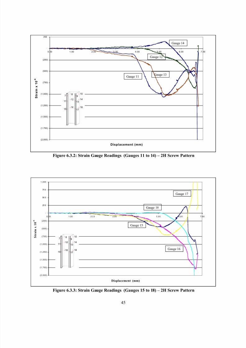
8/2/2019 Design of Bearing Stiffeners in Cold Formed C-Sections
http://slidepdf.com/reader/full/design-of-bearing-stiffeners-in-cold-formed-c-sections 59/151
45
Figure 6.3.2: Strain Gauge Readings (Gauges 11 to 14) – 2H Screw Pattern
Figure 6.3.3: Strain Gauge Readings (Gauges 15 to 18) – 2H Screw Pattern
(2,000)
(1,750)
(1,500)
(1,250)
(1,000)
(750)
(500)
(250)
-
250
0.00 1.00 2.00 3.00 4.00 5.00 6.00 7.00
Displacement (mm)
S t r a i n x 1
0 - 6
78
910
1112
1314
1516
1718
Gauge 11Gauge 13
Gauge 12
Gauge 14
(2,000)
(1,750)
(1,500)
(1,250)
(1,000)
(750)
(500)
(250)
-
25 0
50 0
75 0
1,000
0.00 1.00 2.00 3.00 4.00 5.00 6.00 7.00
Displacement (mm)
S t r a i n x 1 0 - 6
78
910
1112
1314
1516
1718
Gauge 17
Gauge 15
Gauge 16
Gauge 18
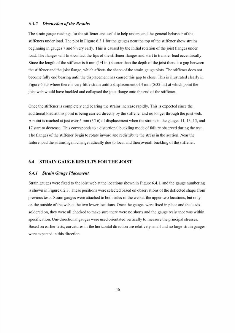
8/2/2019 Design of Bearing Stiffeners in Cold Formed C-Sections
http://slidepdf.com/reader/full/design-of-bearing-stiffeners-in-cold-formed-c-sections 60/151
46
6.3.2 Discussion of the Results
The strain gauge readings for the stiffener are useful to help understand the general behavior of the
stiffeners under load. The plot in Figure 6.3.1 for the gauges near the top of the stiffener show strains
beginning in gauges 7 and 9 very early. This is caused by the initial rotation of the joist flanges under
load. The flanges will first contact the lips of the stiffener flanges and start to transfer load eccentrically.
Since the length of the stiffener is 6 mm (1/4 in.) shorter than the depth of the joist there is a gap between
the stiffener and the joist flange, which affects the shape of the strain gauge plots. The stiffener does not
become fully end bearing until the displacement has caused this gap to close. This is illustrated clearly in
Figure 6.3.3 where there is very little strain until a displacement of 4 mm (5/32 in.) at which point the
joist web would have buckled and collapsed the joist flange onto the end of the stiffener.
Once the stiffener is completely end bearing the strains increase rapidly. This is expected since the
additional load at this point is being carried directly by the stiffener and no longer through the joist web.
A point is reached at just over 5 mm (3/16) of displacement when the strains in the gauges 11, 13, 15, and
17 start to decrease. This corresponds to a distortional buckling mode of failure observed during the test.
The flanges of the stiffener begin to rotate inward and redistribute the stress in the section. Near the
failure load the strains again change radically due to local and then overall buckling of the stiffener.
6.4 STRAIN GAUGE RESULTS FOR THE JOIST
6.4.1 Strain Gauge Placement
Strain gauges were fixed to the joist web at the locations shown in Figure 6.4.1, and the gauge numbering
is shown in Figure 6.2.3. These positions were selected based on observations of the deflected shape from
previous tests. Strain gauges were attached to both sides of the web at the upper two locations, but only
on the outside of the web at the two lower locations. Once the gauges were fixed in place and the leads
soldered on, they were all checked to make sure there were no shorts and the gauge resistance was within
specification. Uni-directional gauges were used orientated vertically to measure the principal stresses.
Based on earlier tests, curvatures in the horizontal direction are relatively small and no large strain gauges
were expected in this direction.
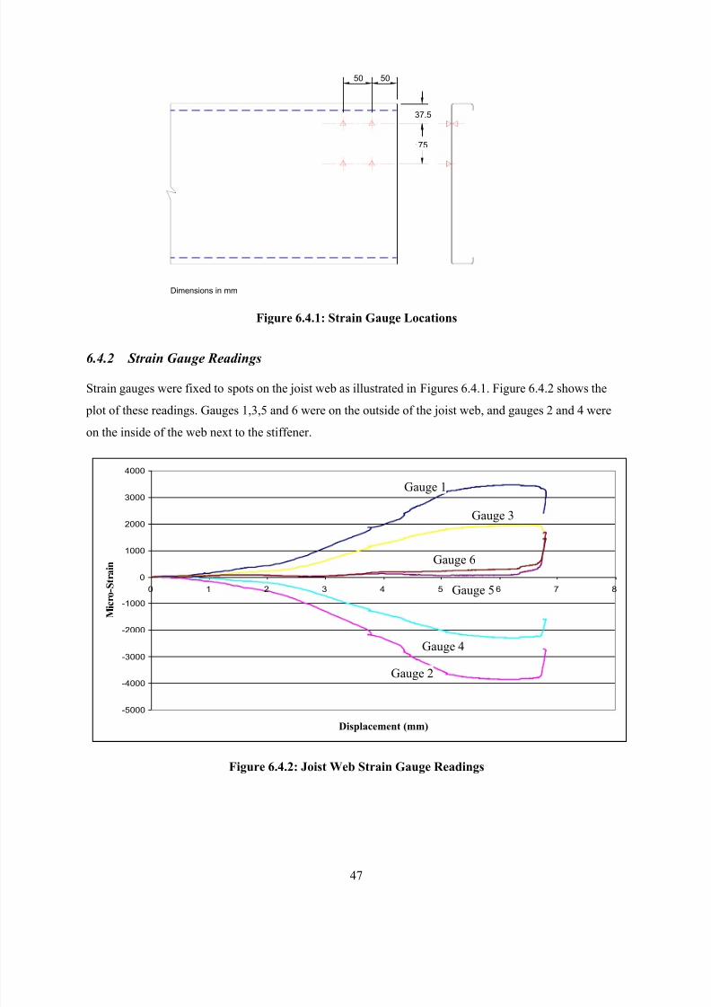
8/2/2019 Design of Bearing Stiffeners in Cold Formed C-Sections
http://slidepdf.com/reader/full/design-of-bearing-stiffeners-in-cold-formed-c-sections 61/151
47
75
37.5
5050
Dimensions in mm
Figure 6.4.1: Strain Gauge Locations
6.4.2 Strain Gauge Readings
Strain gauges were fixed to spots on the joist web as illustrated in Figures 6.4.1. Figure 6.4.2 shows the
plot of these readings. Gauges 1,3,5 and 6 were on the outside of the joist web, and gauges 2 and 4 were
on the inside of the web next to the stiffener.
Figure 6.4.2: Joist Web Strain Gauge Readings
-5000
-4000
-3000
-2000
-1000
0
1000
2000
3000
4000
0 1 2 3 4 5 6 7 8
Displacement (mm)
M i c r o - S t r a i n
Gauge 1
Gauge 2
Gauge 3
Gauge 4
Gauge 5
Gauge 6
8/2/2019 Design of Bearing Stiffeners in Cold Formed C-Sections
http://slidepdf.com/reader/full/design-of-bearing-stiffeners-in-cold-formed-c-sections 62/151
48
6.4.3 Discussion of the Results
The strain gauges for the joist readings confirms what would be expected based on the observed deformed
shape. These results will be used in Section 7 in conjunction with the analysis of the measured web
buckling, as well as being used in Section 8 to verify the finite element model.
8/2/2019 Design of Bearing Stiffeners in Cold Formed C-Sections
http://slidepdf.com/reader/full/design-of-bearing-stiffeners-in-cold-formed-c-sections 63/151
49
7 WEB BUCKLING MEASUREMENTS AND ANALYSIS
7.1 OBJECTIVE AND SCOPE
The objective of this phase of the work was to provide physical data on the buckled shape of the joist web
to determine the stresses in the joist web as well as verify the finite element model.
The scope of this work was as follows:
• Conduct a test of a C-section subjected to end-two-flange loading.
• Measure the deflected shape of the web at intervals during the load cycle.
• Mathematically model the deflected shape of the joist web and determine the in-plane strains due
to bending.
• Determine the in-plane bending and axial stresses.
Three different web buckling tests were carried out. The following is a discussion of the last test
conducted (which benefited from the experience gained in the first two tests) and presents the test
methodology and analytical methods that are used.
7.2 SPECIMEN DIMENSIONS AND TEST SET-UP
7.2.1 Specimen Dimensions and Physical Properties
Figure 7.2.1 shows a photograph of the test specimen and test set-up. This is the same specimen used in
the strain gauge measurement tests that was discussed in Section 6. The dimensions and material
properties for the specimen are provided in Figures 6.2.1 and 6.2.1 and Table 6.2.1. Two fasteners were
used to connect the joist web to the stiffener and were placed as indicated in Figure 7.2.2. The stiffener
was positioned 5 mm (3/16 in.) in from the end of the joist to ensure bearing of the stiffener over its entire
end area.
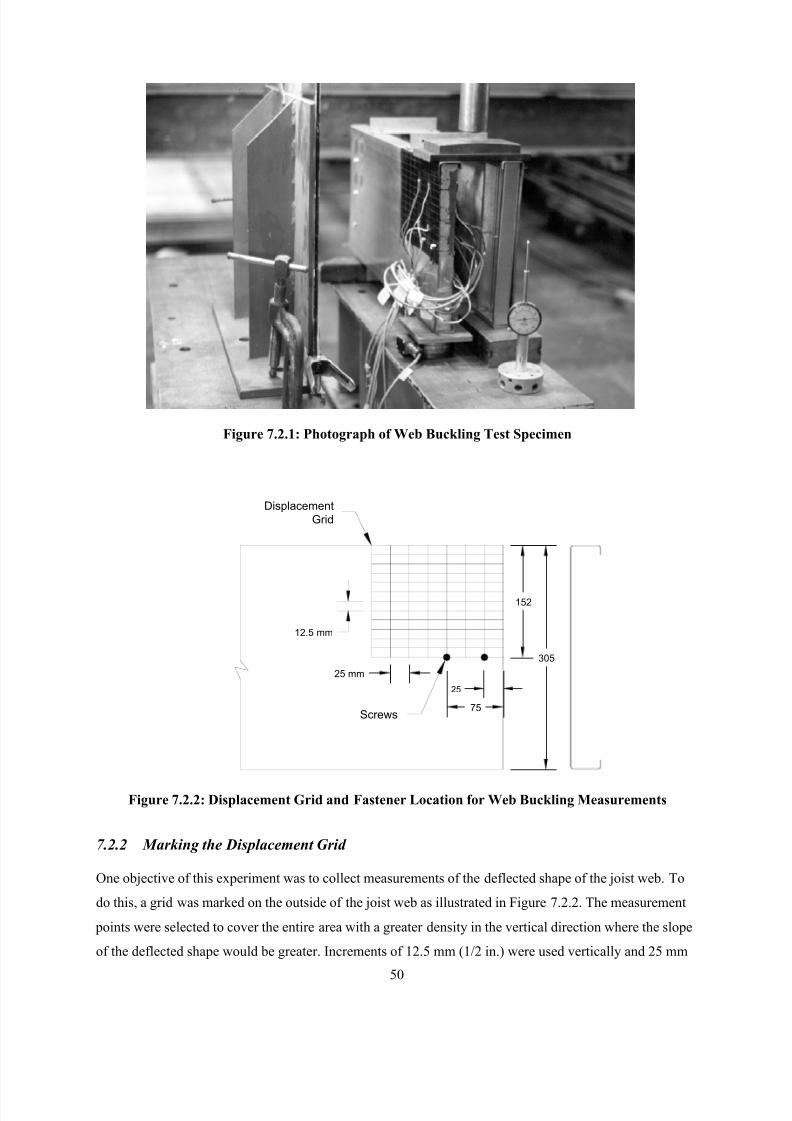
8/2/2019 Design of Bearing Stiffeners in Cold Formed C-Sections
http://slidepdf.com/reader/full/design-of-bearing-stiffeners-in-cold-formed-c-sections 64/151
50
Figure 7.2.1: Photograph of Web Buckling Test Specimen
12.5 mm
25 mm
152
305
25
75
Displacement
Grid
Screws
Figure 7.2.2: Displacement Grid and Fastener Location for Web Buckling Measurements
7.2.2 Marking the Displacement Grid
One objective of this experiment was to collect measurements of the deflected shape of the joist web. To
do this, a grid was marked on the outside of the joist web as illustrated in Figure 7.2.2. The measurement
points were selected to cover the entire area with a greater density in the vertical direction where the slope
of the deflected shape would be greater. Increments of 12.5 mm (1/2 in.) were used vertically and 25 mm
8/2/2019 Design of Bearing Stiffeners in Cold Formed C-Sections
http://slidepdf.com/reader/full/design-of-bearing-stiffeners-in-cold-formed-c-sections 65/151
51
(1 in.) increments horizontally. The grid covered only one half of the web depth since the deflected shape
is typically symmetrical.
7.2.3 Measurement Devices
A dial gauge and an LVDT were used to measure the horizontal and vertical deflections. A rigid vertical
reference plane was positioned to provide the necessary datum point on which a clean glass surface was
mounted. A dial gauge was fixed to a movable base and positioned at each grid point sequentially and the
distance measured between the joist web and the reference surface. Dial gauge measurements in 1/100 of
a millimetre were recorded. An LVDT was used to measure the vertical deflection of the top bearing plate
to give the overall shortening of the web. This device provided measurements in 1/10 of a millimetre.
In addition to measuring the deflected shape, two load cells were also used. One load cell was part of the
hydraulic ram and recorded the total load applied to the entire specimen. The other load cell was
positioned under the joist being measured to record its share of the total load. Each cell measured the load
to within 1/100 of a kiloNewton.
7.2.4 Data Collection
Measurements were taken at five intervals: after an initial pre-load, and then at 25%, 50%, and 75% of the
anticipated failure load and then finally at the failure load. Based on earlier tests, the failure load was
predicted to be 40 kN. The load cell and strain gauge outputs were recorded with LabView, acomputerized data collection system. Readings were taken at regular intervals during the load application
and then paused during the time it took to measure the deflections with the dial gauge.
7.3 DATA COLLECTION
7.3.1 Deflected Shape of the Web
The data from the measurements of the web deflection at the five load increments are given in Appendix
C. These measurements are relative to the deflected shape measured at the initial pre-load stage. The web
profile at a load of 13.09 kN (2,940 lbs) (load on the single stiffener) is shown graphically in Figure 7.3.1.
This represents only the upper half of the joist web. The load was applied over grid numbers A through E
along row 0. The fasteners were located at grid points B13 and D13. At failure, the bearing stiffener was
subject to local buckling in some elements and the forces exerted by the joist web caused the assembly to
buckle out of plane. The deflected shape at the failure load is shown in Figure 7.3.2. The deflected shape
prior to failure as shown in Figure 7.3.1 is typical of the types of failure modes most often observed, and
subsequently was used for the analysis.
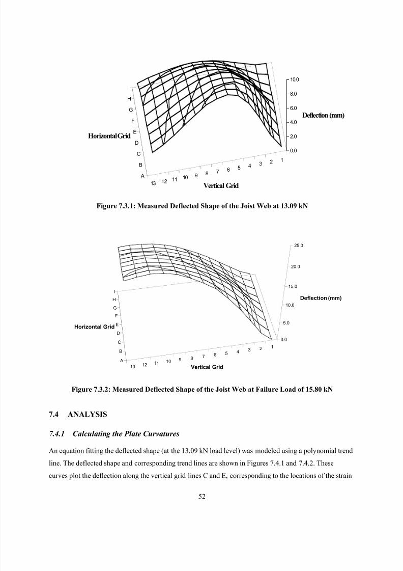
8/2/2019 Design of Bearing Stiffeners in Cold Formed C-Sections
http://slidepdf.com/reader/full/design-of-bearing-stiffeners-in-cold-formed-c-sections 66/151
52
12345678910111213
I
H
G
F
E
D
C
B
A
0.0
2.0
4.0
6.0
8.0
10.0
Deflection (mm)
Vertical Grid
Horizontal Grid
Figure 7.3.1: Measured Deflected Shape of the Joist Web at 13.09 kN
Figure 7.3.2: Measured Deflected Shape of the Joist Web at Failure Load of 15.80 kN
7.4 ANALYSIS
7.4.1 Calculating the Plate Curvatures
An equation fitting the deflected shape (at the 13.09 kN load level) was modeled using a polynomial trend
line. The deflected shape and corresponding trend lines are shown in Figures 7.4.1 and 7.4.2. These
curves plot the deflection along the vertical grid lines C and E, corresponding to the locations of the strain
12345678910111213
I
H
G
F
E
D
C
B
A
0.0
5.0
10.0
15.0
20.0
25.0
Deflection (mm)
Vertical Grid
Horizontal Grid

8/2/2019 Design of Bearing Stiffeners in Cold Formed C-Sections
http://slidepdf.com/reader/full/design-of-bearing-stiffeners-in-cold-formed-c-sections 67/151
53
gauges. Two additional curves are plotted in Figures 7.4.3 and 7.4.4 showing the deflected shapes along
horizontal rows 3 and 10, also corresponding to the locations of the strain gauges.
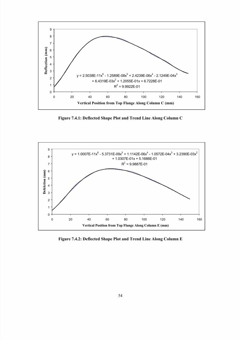
8/2/2019 Design of Bearing Stiffeners in Cold Formed C-Sections
http://slidepdf.com/reader/full/design-of-bearing-stiffeners-in-cold-formed-c-sections 68/151
54
Figure 7.4.1: Deflected Shape Plot and Trend Line Along Column C
Figure 7.4.2: Deflected Shape Plot and Trend Line Along Column E
y = 2.5038E-11x6
- 1.2589E-08x5
+ 2.4239E-06x4
- 2.1249E-04x3
+ 6.4319E-03x2
+ 1.2055E-01x + 6.7228E-01
R2
= 9.9922E-01
0
1
2
3
4
5
6
7
8
9
0 20 40 60 80 100 120 140 160
Vertical Position from Top Flange Along Column C (mm)
D e f l e c t i o n ( m m )
y = 1.0007E-11x6
- 5.3731E-09x5
+ 1.1142E-06x4
- 1.0572E-04x3
+ 3.2390E-03x2
+ 1.0307E-01x + 5.1686E-01
R2
= 9.9887E-01
0
1
2
3
4
5
6
7
8
9
0 20 40 60 80 100 120 140 160
Vertical Position from Top Flange Along Column E (mm)
D e f e l c t i o n
( m m )
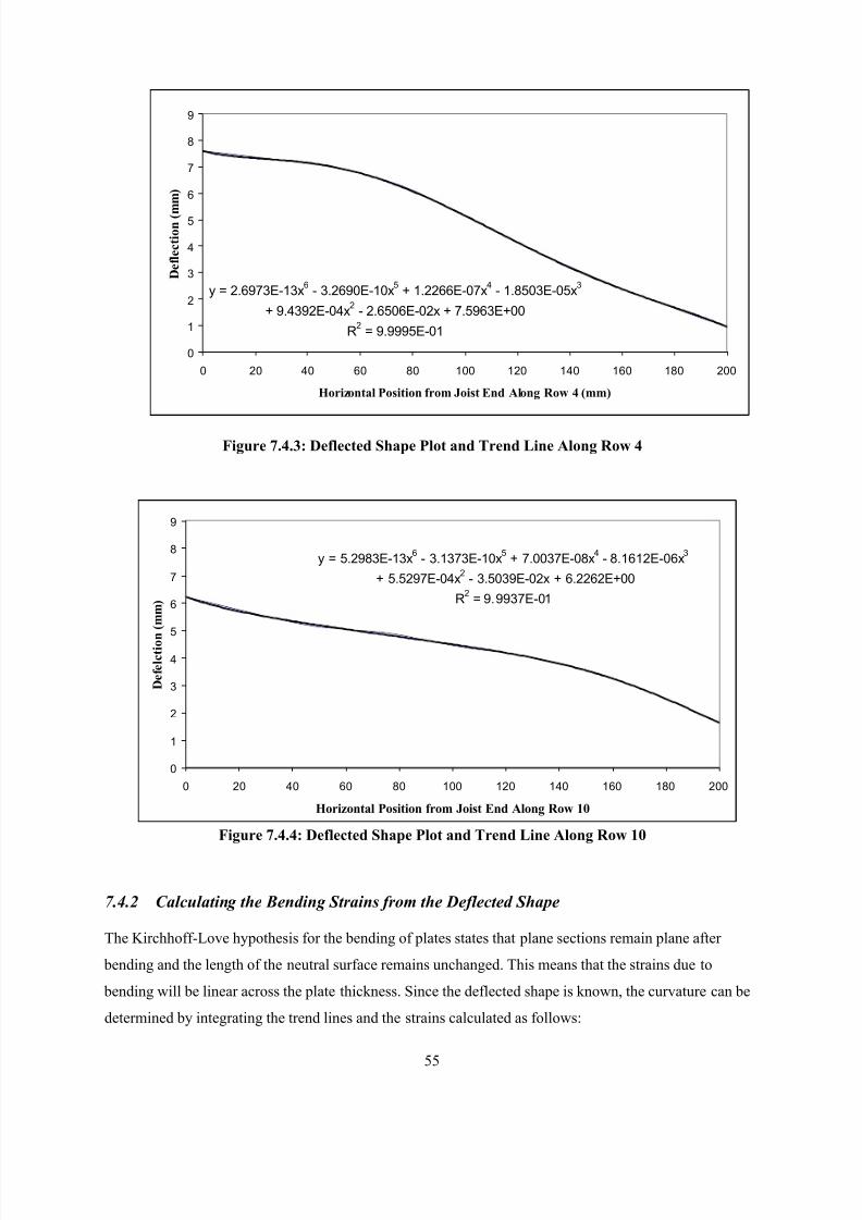
8/2/2019 Design of Bearing Stiffeners in Cold Formed C-Sections
http://slidepdf.com/reader/full/design-of-bearing-stiffeners-in-cold-formed-c-sections 69/151
55
Figure 7.4.3: Deflected Shape Plot and Trend Line Along Row 4
Figure 7.4.4: Deflected Shape Plot and Trend Line Along Row 10
7.4.2 Calculating the Bending Strains from the Deflected Shape
The Kirchhoff-Love hypothesis for the bending of plates states that plane sections remain plane after
bending and the length of the neutral surface remains unchanged. This means that the strains due to
bending will be linear across the plate thickness. Since the deflected shape is known, the curvature can be
determined by integrating the trend lines and the strains calculated as follows:
y = 2.6973E-13x6
- 3.2690E-10x5
+ 1.2266E-07x4
- 1.8503E-05x3
+ 9.4392E-04x2
- 2.6506E-02x + 7.5963E+00
R2
= 9.9995E-01
0
1
2
3
4
5
6
7
8
9
0 20 40 60 80 100 120 140 160 180 200
Horizontal Position from Joist End Along Row 4 (mm)
D e f l e c t i o n ( m
m )
y = 5.2983E-13x6
- 3.1373E-10x5
+ 7.0037E-08x4
- 8.1612E-06x3
+ 5.5297E-04x2
- 3.5039E-02x + 6.2262E+00
R2
= 9.9937E-01
0
1
2
3
4
5
6
7
8
9
0 20 40 60 80 100 120 140 160 180 200
Horizontal Position from Joist End Along Row 10
D e f e l c t i o n ( m m )
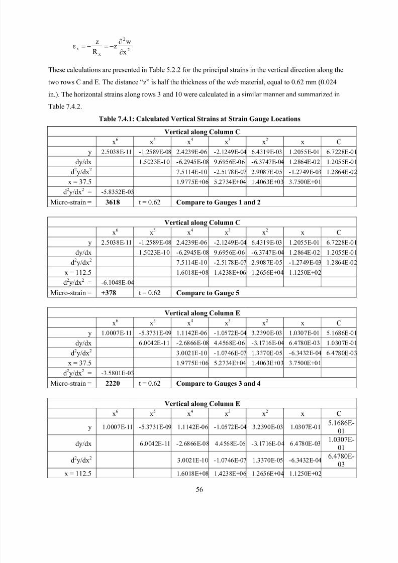
8/2/2019 Design of Bearing Stiffeners in Cold Formed C-Sections
http://slidepdf.com/reader/full/design-of-bearing-stiffeners-in-cold-formed-c-sections 70/151
56
2
2
x
xx
wz
R
z
∂
∂−=−=ε
These calculations are presented in Table 5.2.2 for the principal strains in the vertical direction along the
two rows C and E. The distance “z” is half the thickness of the web material, equal to 0.62 mm (0.024
in.). The horizontal strains along rows 3 and 10 were calculated in a similar manner and summarized in
Table 7.4.2.
Table 7.4.1: Calculated Vertical Strains at Strain Gauge Locations
Vertical along Column C
x6 x5 x4 x3 x2 x C
y 2.5038E-11 -1.2589E-08 2.4239E-06 -2.1249E-04 6.4319E-03 1.2055E-01 6.7228E-01
dy/dx 1.5023E-10 -6.2945E-08 9.6956E-06 -6.3747E-04 1.2864E-02 1.2055E-01
d2y/dx2 7.5114E-10 -2.5178E-07 2.9087E-05 -1.2749E-03 1.2864E-02
x = 37.5 1.9775E+06 5.2734E+04 1.4063E+03 3.7500E+01
d2y/dx2 = -5.8352E-03
Micro-strain = 3618 t = 0.62 Compare to Gauges 1 and 2
Vertical along Column C
x6 x5 x4 x3 x2 x C
y 2.5038E-11 -1.2589E-08 2.4239E-06 -2.1249E-04 6.4319E-03 1.2055E-01 6.7228E-01
dy/dx 1.5023E-10 -6.2945E-08 9.6956E-06 -6.3747E-04 1.2864E-02 1.2055E-01
d2y/dx2 7.5114E-10 -2.5178E-07 2.9087E-05 -1.2749E-03 1.2864E-02
x = 112.5 1.6018E+08 1.4238E+06 1.2656E+04 1.1250E+02
d2y/dx2 = -6.1048E-04
Micro-strain = +378 t = 0.62 Compare to Gauge 5
Vertical along Column E
x6 x5 x4 x3 x2 x C
y 1.0007E-11 -5.3731E-09 1.1142E-06 -1.0572E-04 3.2390E-03 1.0307E-01 5.1686E-01
dy/dx 6.0042E-11 -2.6866E-08 4.4568E-06 -3.1716E-04 6.4780E-03 1.0307E-01
d2y/dx2 3.0021E-10 -1.0746E-07 1.3370E-05 -6.3432E-04 6.4780E-03
x = 37.5 1.9775E+06 5.2734E+04 1.4063E+03 3.7500E+01
d2y/dx2 = -3.5801E-03
Micro-strain = 2220 t = 0.62 Compare to Gauges 3 and 4
Vertical along Column E
x6 x5 x4 x3 x2 x C
y 1.0007E-11 -5.3731E-09 1.1142E-06 -1.0572E-04 3.2390E-03 1.0307E-015.1686E-
01
dy/dx 6.0042E-11 -2.6866E-08 4.4568E-06 -3.1716E-04 6.4780E-031.0307E-
01
d2y/dx2 3.0021E-10 -1.0746E-07 1.3370E-05 -6.3432E-046.4780E-
03
x = 112.5 1.6018E+08 1.4238E+06 1.2656E+04 1.1250E+02
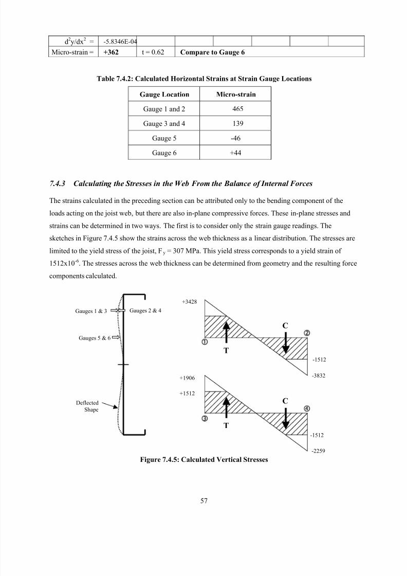
8/2/2019 Design of Bearing Stiffeners in Cold Formed C-Sections
http://slidepdf.com/reader/full/design-of-bearing-stiffeners-in-cold-formed-c-sections 71/151
57
d2y/dx2 = -5.8346E-04
Micro-strain = +362 t = 0.62 Compare to Gauge 6
Table 7.4.2: Calculated Horizontal Strains at Strain Gauge Locations
Gauge Location Micro-strain
Gauge 1 and 2 465
Gauge 3 and 4 139
Gauge 5 -46
Gauge 6 +44
7.4.3 Calculating the Stresses in the Web From the Balance of Internal Forces
The strains calculated in the preceding section can be attributed only to the bending component of the
loads acting on the joist web, but there are also in-plane compressive forces. These in-plane stresses and
strains can be determined in two ways. The first is to consider only the strain gauge readings. The
sketches in Figure 7.4.5 show the strains across the web thickness as a linear distribution. The stresses are
limited to the yield stress of the joist, Fy = 307 MPa. This yield stress corresponds to a yield strain of
1512x10-6. The stresses across the web thickness can be determined from geometry and the resulting force
components calculated.
Figure 7.4.5: Calculated Vertical Stresses
-2259
-1512
-3832
-1512
C
T
Gauges 5 & 6
Gauges 2 & 4Gauges 1 & 3
DeflectedShape
+3428
+1512
+1906
T
C
8/2/2019 Design of Bearing Stiffeners in Cold Formed C-Sections
http://slidepdf.com/reader/full/design-of-bearing-stiffeners-in-cold-formed-c-sections 72/151
58
At strain gauge locations 1 & 2:
T = 140 N/mm of length C = 161 N/mm of length
Net compression = 21 N/mm = 17 MPa (for 1.24 mm thick web)
At strain gauge locations 3 & 4:
T = 105 N/mm of length C = 137 N/mm of length
Net compression = 32 N/mm = 26 MPa (for 1.24 mm thick web)
7.4.4 Calculating the Stresses in the Web From Measured Curvatures
The in-plane stresses can also be determined using the strains calculated from the deflected shape along
with the measured strains.
Table 7.4.3: Calculated In-Plane Strains and Stresses
Gauge 1 Gauge 2 Gauge 3 Gauge 4
Measured micro-strain
from strain gauges+3428 -3832 +1906 -2259
Micro-strain from
measured curvature+3618 -3618 +2200 -2200
In-plane component of
strain-190 -214 -314 -39
Average in-plane
compressive micro-strain202 177
Average in-plane
compressive stress41 MPa 36 MPa
7.4.5 Calculating the Stresses in the Web From Web Crippling Calculations
One hypothesis about the behavior of a C-section with a bearing stiffener is that the capacity of the
stiffened assembly is the addition of the web crippling capacity of the joist web and the axial capacity of
the stiffener. Due to the restraint provided to the joist web by the stiffener, it can be argued that the web
crippling of the stiffened joist behaves more like a built-up section than a single web member. This
behavior can be also be used in the web buckling analysis. The web crippling capacity of a built-up I-section composed of two channels back-to-back, calculated according to the equation proposed by
Beshara [9] is as follows:
( )( )( )( )HC1 NC1R C1sinFCtP H NR y2
r −+−θ=
Where,
C = 15.5
CR = 0.09
C N = 0.08
8/2/2019 Design of Bearing Stiffeners in Cold Formed C-Sections
http://slidepdf.com/reader/full/design-of-bearing-stiffeners-in-cold-formed-c-sections 73/151
59
CH = 0.04
h = 305 mm
t = 1.24 mm
Fy = 307 MPa
= 90
R = 2
N = 100/1.24 = 81
H = 297/1.24 = 240 (this is over the maximum limit of 200 in the AISI Specification)
Pr = (15.5)(1.24)2(307)(1)(1 - 0.09 2 )(1 + 0.08 81 )(1 – 0.04 240 )
= 4.18 kN
This web crippling load corresponds to an in-plane stress in the web of 34 MPa under the bearing plate.
7.4.6 Comparisons
When the three solutions are compared they show some similarity:
a) 17 MPa calculated from the balance of internal forces,
b) 41 MPa calculated from the measured deflected shape, and
c) 34 MPa calculated from the web crippling capacity.
Some caution needs to be used in inferring anything from these results. The stress determined from the
web crippling expression assumes a uniform stress distribution under the applied load. While this may be
a reasonable assumption directly under the bearing plate, the stress pattern will change at different
locations through the joist web. There are also other errors associated with the measurement procedures as
discussed in the next section.
7.4.7 Sources of Error
There are a number of sources of error inherent in this type of data collection.
a) Error during the measurement of the deflected shape. The dial gauge used to measure the deflected
shape was capable of measuring to 1/1000 mm. However, the necessity of moving this gauge from
one location to another introduced some variability in the repeatability of the measurements. To get
an estimate of this error, a number of measurements were repeated and the two sets of data compared.
The average difference between the two measurements (for 53 measurements) was 0.1%.
b) Integration of the deflected shape: The strains were determined through a double integration of the
measured displacement field. The calculation of the gradients of the displacements will be subject to
increasing errors. Any errors in the measurement of the deflected shape will be magnified through the
process of integration.
8/2/2019 Design of Bearing Stiffeners in Cold Formed C-Sections
http://slidepdf.com/reader/full/design-of-bearing-stiffeners-in-cold-formed-c-sections 74/151
60
c) Experimental error : 1% error in the gauge factor. 0.1% in the measurement of the load. 1% possible
error in the strain gauge measurements.
d) Bi-axial stress field : An assumption has been made that the principal stresses are vertical in the
orientation of the strain gauges. In fact, the orientation of the principal stresses is likely to vary over
the web area. The deflected shape shows that there is some curvature in the longitudinal direction
which were not included in the analysis.
7.5 CONCLUSIONS
The experimental method described in this section has arrived at an estimate of the in-plane stresses in the
joist web due to the web crippling. While there is variability in the results, they are close enough to
provide some confidence that using the measured deflected shape to determine the bending strains in the
web is a viable means of providing data as input to the finite element program.
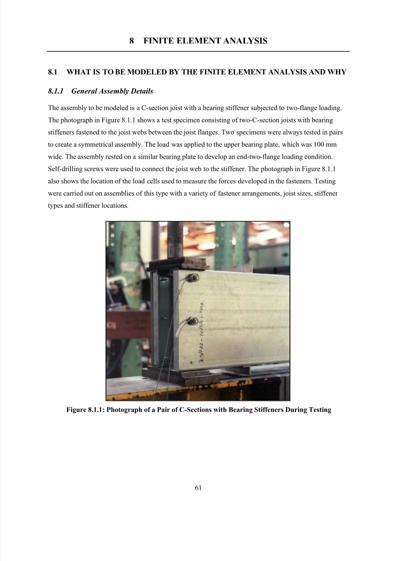
8/2/2019 Design of Bearing Stiffeners in Cold Formed C-Sections
http://slidepdf.com/reader/full/design-of-bearing-stiffeners-in-cold-formed-c-sections 75/151
61
8 FINITE ELEMENT ANALYSIS
8.1 WHAT IS TO BE MODELED BY THE FINITE ELEMENT ANALYSIS AND WHY
8.1.1 General Assembly Details
The assembly to be modeled is a C-section joist with a bearing stiffener subjected to two-flange loading.
The photograph in Figure 8.1.1 shows a test specimen consisting of two-C-section joists with bearing
stiffeners fastened to the joist webs between the joist flanges. Two specimens were always tested in pairs
to create a symmetrical assembly. The load was applied to the upper bearing plate, which was 100 mm
wide. The assembly rested on a similar bearing plate to develop an end-two-flange loading condition.
Self-drilling screws were used to connect the joist web to the stiffener. The photograph in Figure 8.1.1
also shows the location of the load cells used to measure the forces developed in the fasteners. Testing
were carried out on assemblies of this type with a variety of fastener arrangements, joist sizes, stiffener types and stiffener locations.
Figure 8.1.1: Photograph of a Pair of C-Sections with Bearing Stiffeners During Testing
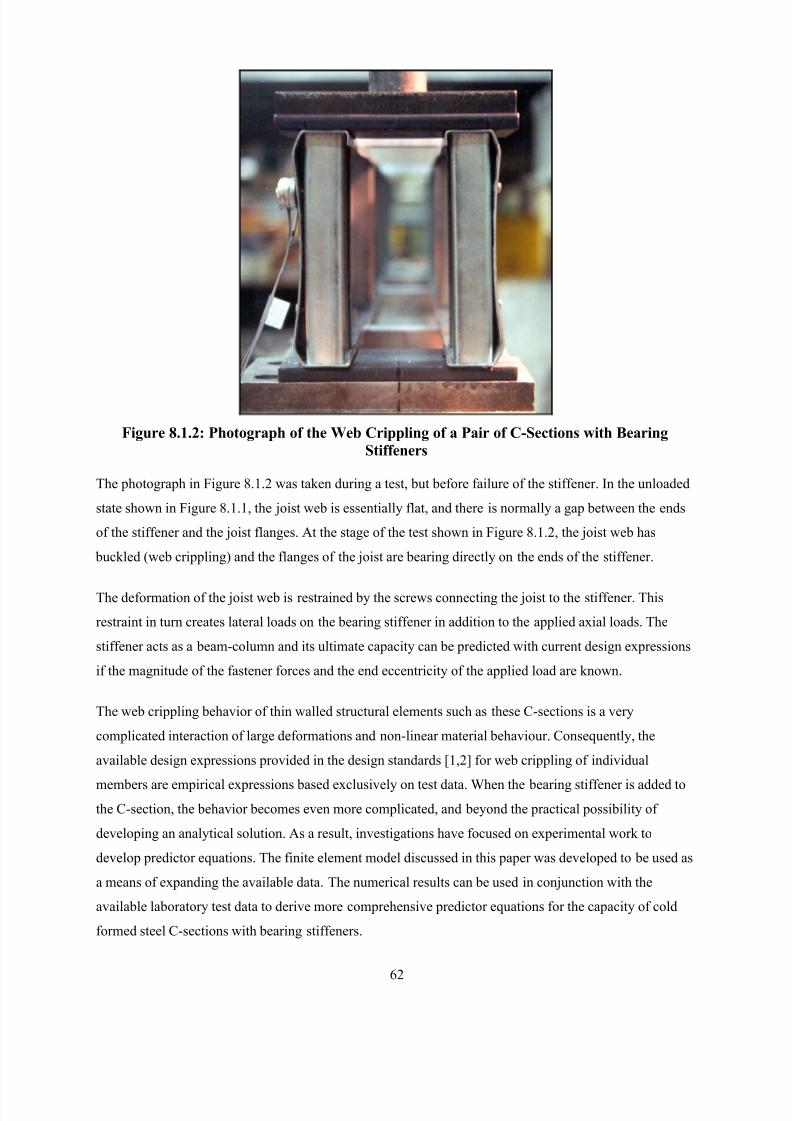
8/2/2019 Design of Bearing Stiffeners in Cold Formed C-Sections
http://slidepdf.com/reader/full/design-of-bearing-stiffeners-in-cold-formed-c-sections 76/151
62
Figure 8.1.2: Photograph of the Web Crippling of a Pair of C-Sections with Bearing
Stiffeners
The photograph in Figure 8.1.2 was taken during a test, but before failure of the stiffener. In the unloaded
state shown in Figure 8.1.1, the joist web is essentially flat, and there is normally a gap between the ends
of the stiffener and the joist flanges. At the stage of the test shown in Figure 8.1.2, the joist web has
buckled (web crippling) and the flanges of the joist are bearing directly on the ends of the stiffener.
The deformation of the joist web is restrained by the screws connecting the joist to the stiffener. This
restraint in turn creates lateral loads on the bearing stiffener in addition to the applied axial loads. The
stiffener acts as a beam-column and its ultimate capacity can be predicted with current design expressions
if the magnitude of the fastener forces and the end eccentricity of the applied load are known.
The web crippling behavior of thin walled structural elements such as these C-sections is a very
complicated interaction of large deformations and non-linear material behaviour. Consequently, the
available design expressions provided in the design standards [1,2] for web crippling of individual
members are empirical expressions based exclusively on test data. When the bearing stiffener is added to
the C-section, the behavior becomes even more complicated, and beyond the practical possibility of
developing an analytical solution. As a result, investigations have focused on experimental work to
develop predictor equations. The finite element model discussed in this paper was developed to be used as
a means of expanding the available data. The numerical results can be used in conjunction with the
available laboratory test data to derive more comprehensive predictor equations for the capacity of cold
formed steel C-sections with bearing stiffeners.
8/2/2019 Design of Bearing Stiffeners in Cold Formed C-Sections
http://slidepdf.com/reader/full/design-of-bearing-stiffeners-in-cold-formed-c-sections 77/151
63
8.1.2 Key Characteristics and Behavior to be Numerically Modeled
The finite element model must capture a number of key characteristics of the assembly and its behaviour
under load.
8.1.2.1 Deformed Shape
The results of the FEA must predict the basic deformed shape of the joist web in general agreement with
that observed during the laboratory tests.
8.1.2.2 Stiffener End Gap
A certain amount of gap between the stiffener and the joist is necessary to accommodate manufacturing
tolerances, and to make the assembly easier. The current industry standards for cold formed steel are the
AISI Standard for Cold-Formed Steel Framing - General Requirements [20], and the CSSBI 55-99
Residential Steel Framing Installation Manual [21]. These documents stipulate that a bearing stiffener
can only be 9 mm (3/8 in.) shorter than the joist depth. Taking into account the thickness of the joist
material, this corresponds to a gap of approximately 3 mm (1/8 in.) at each end of the stiffener.
8.1.2.3 Contact Area
During the deformation of the assembly under load, the joist web buckles in a complicated shape (as
illustrated in Figure 8.1.2). Typically, the area directly under the bearing plate will bulge outwards (away
from the stiffener), and the area near the centre of the web will deflect towards the stiffener. The presence
of the bearing stiffener, however, will restrict the inward deformation of the joist web. Since the web
crippling capacity and fastener forces are influenced by the deformed shape, it is important that the FEmodel account for the possibility that these two elements (the joist web and the stiffener) may come into
contact during the loading cycle.
8.1.2.4 Non-linearity
The FE model must also account for the geometric non-linearity resulting from large deformations, as
well as the material non-linearity in those areas where the strains goes beyond the elastic limit.
8.1.2.5 Fastener Flexibility
The stiffness of the fasteners connecting the joist web to the bearing stiffener will restrain the deformation
of the joist web, both locally and overall. The degree of restraint will be affected by the location of the
fastener in the joist web, as well as the material strength and thickness of the bearing stiffener to which
the fastener is connected.
8.1.3 Required Results/Output
The finite element model is primarily being used to supply only the following two results.
8/2/2019 Design of Bearing Stiffeners in Cold Formed C-Sections
http://slidepdf.com/reader/full/design-of-bearing-stiffeners-in-cold-formed-c-sections 78/151
64
8.1.3.1 Web Crippling Capacity
Since there is a gap between the bearing stiffener and the joist flanges, the joist web will buckle (web
crippling) at a load that can be significantly less than the ultimate load of the entire assembly. This
condition would be a serviceability limit state for the assembly. In practice, the assembly should be
designed to avoid web crippling at service loads for aesthetic reasons as well as the implications for
accumulated deformations through multiple storeys, and the possible affects on brittle connected finishes.
One of the required results from the FEA will be the web crippling capacity of the joist.
8.1.3.2 Fastener Forces
The capacity of the bearing stiffener is a function of the axial load, the end eccentricity and the lateral
loads at the screw locations. The FEA must provide the fastener forces, which can be used in subsequent
studies to determine the strength limit state for the stiffened assembly.
8.2 GENERAL FEATURES OF THE FINITE ELEMENT MODELING
8.2.1 FE Program
The finite element program used for this analysis was the ANSYS 5.6 program. This is a commercially
available computer program that provides for a wide range of analyzes, including the features necessary
for this study. No attempt was made to compare alternative programs. The ANSYS program was installed
and run on a personal computer.
8.2.2 Element Types
8.2.2.1 Shell Elements
The basic behavior to be modeled was the deflected shape of thin sheet steel elements representing the
joist. It was necessary to account for both the in-plane stresses and bending behavior, as well as model the
curvature of the deflected shape with the fewest elements. Shell93 elements were used, which have mid-
side nodes (8 node quadrilateral) with six degrees of freedom at each node (3 displacement and 3
rotation). These elements were used to mesh all of the surface areas.
8.2.2.2 Contact ElementsThe ANSYS 5.6 program is able to model contact between designated target and contact areas utilizing
elements that are overlaid on the Shell93 meshed areas. The contact pairs used were the Targe170 for the
area that is taken to be stationary, and Conta174 elements for the area that changes its position. The target
area represents the bearing stiffener and the contact area is an area of the joist web.
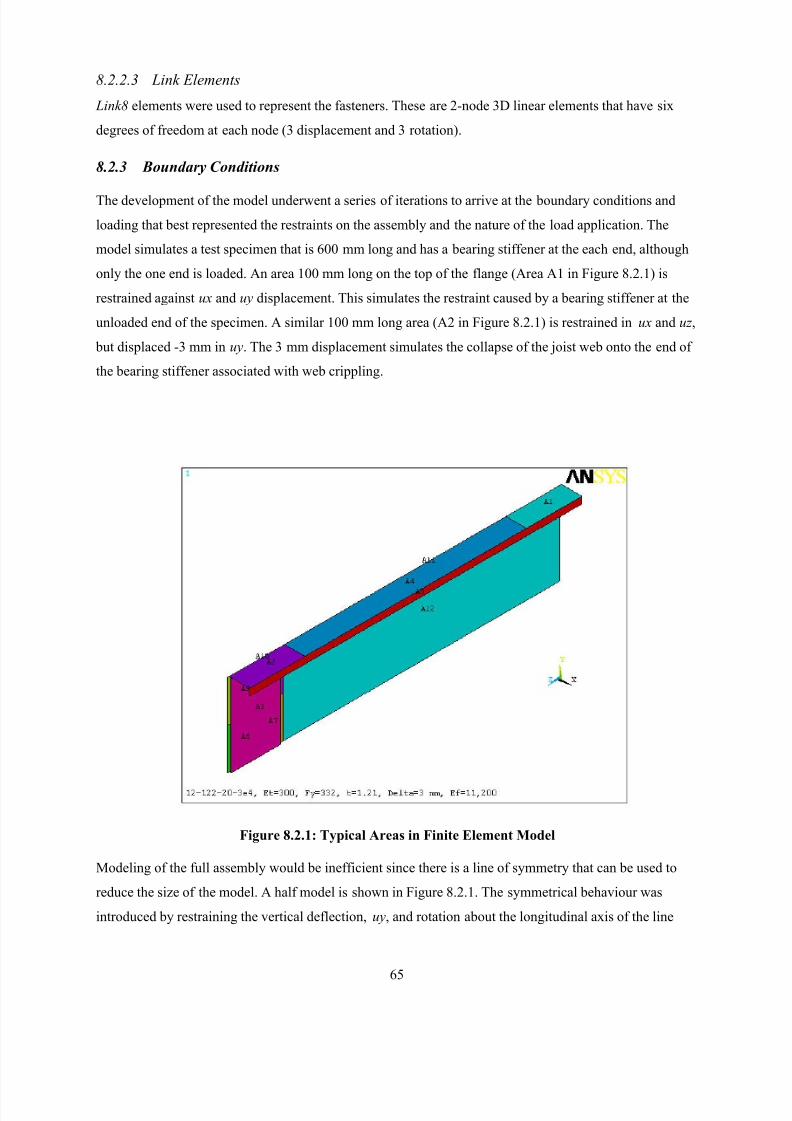
8/2/2019 Design of Bearing Stiffeners in Cold Formed C-Sections
http://slidepdf.com/reader/full/design-of-bearing-stiffeners-in-cold-formed-c-sections 79/151
65
8.2.2.3 Link Elements
Link8 elements were used to represent the fasteners. These are 2-node 3D linear elements that have six
degrees of freedom at each node (3 displacement and 3 rotation).
8.2.3 Boundary Conditions
The development of the model underwent a series of iterations to arrive at the boundary conditions and
loading that best represented the restraints on the assembly and the nature of the load application. The
model simulates a test specimen that is 600 mm long and has a bearing stiffener at the each end, although
only the one end is loaded. An area 100 mm long on the top of the flange (Area A1 in Figure 8.2.1) is
restrained against ux and uy displacement. This simulates the restraint caused by a bearing stiffener at the
unloaded end of the specimen. A similar 100 mm long area (A2 in Figure 8.2.1) is restrained in ux and uz ,
but displaced -3 mm in uy. The 3 mm displacement simulates the collapse of the joist web onto the end of
the bearing stiffener associated with web crippling.
Figure 8.2.1: Typical Areas in Finite Element Model
Modeling of the full assembly would be inefficient since there is a line of symmetry that can be used to
reduce the size of the model. A half model is shown in Figure 8.2.1. The symmetrical behaviour was
introduced by restraining the vertical deflection, uy, and rotation about the longitudinal axis of the line
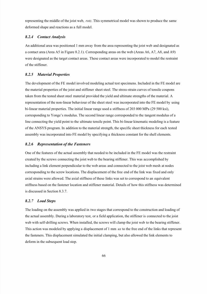
8/2/2019 Design of Bearing Stiffeners in Cold Formed C-Sections
http://slidepdf.com/reader/full/design-of-bearing-stiffeners-in-cold-formed-c-sections 80/151
66
representing the middle of the joist web, rotz . This symmetrical model was shown to produce the same
deformed shape and reactions as a full model.
8.2.4 Contact Analysis
An additional area was positioned 1 mm away from the area representing the joist web and designated as
a contact area (Area A5 in Figure 8.2.1). Corresponding areas on the web (Areas A6, A7, A8, and A9)
were designated as the target contact areas. These contact areas were incorporated to model the restraint
of the stiffener.
8.2.5 Material Properties
The development of the FE model involved modeling actual test specimens. Included in the FE model are
the material properties of the joist and stiffener sheet steel. The stress-strain curves of tensile coupons
taken from the tested sheet steel material provided the yield and ultimate strengths of the material. A
representation of the non-linear behaviour of the sheet steel was incorporated into the FE model by using
bi-linear material properties. The initial linear range used a stiffness of 203 000 MPa (29 500 ksi),
corresponding to Yonge’s modulus. The second linear range corresponded to the tangent modulus of a
line connecting the yield point to the ultimate tensile point. This bi-linear kinematic modeling is a feature
of the ANSYS program. In addition to the material strength, the specific sheet thickness for each tested
assembly was incorporated into FE model by specifying a thickness constant for the shell elements.
8.2.6 Representation of the Fasteners
One of the features of the actual assembly that needed to be included in the FE model was the restraintcreated by the screws connecting the joist web to the bearing stiffener. This was accomplished by
including a link element perpendicular to the web areas and connected to the joist web mesh at nodes
corresponding to the screw locations. The displacement of the free end of the link was fixed and only
axial strains were allowed. The axial stiffness of these links was set to correspond to an equivalent
stiffness based on the fastener location and stiffener material. Details of how this stiffness was determined
is discussed in Section 8.3.7.
8.2.7 Load Steps
The loading on the assembly was applied in two stages that correspond to the construction and loading of
the actual assembly. During a laboratory test, or a field application, the stiffener is connected to the joist
web with self-drilling screws. When installed, the screws will clamp the joist web to the bearing stiffener.
This action was modeled by applying a displacement of 1 mm ux to the free end of the links that represent
the fasteners. This displacement simulated the initial clamping, but also allowed the link elements to
deform in the subsequent load step.
8/2/2019 Design of Bearing Stiffeners in Cold Formed C-Sections
http://slidepdf.com/reader/full/design-of-bearing-stiffeners-in-cold-formed-c-sections 81/151
67
The second load step was a –3 mm uy displacement of the area under the bearing surface. This
corresponds to the application of the applied load above the bearing stiffener. Three millimetres of
deflection was used to model the deformation exhibited in the laboratory tests. The two load steps were
applied sequentially.
8.2.8 Meshing the Model
The model was meshed with the two contrary objectives: to create a sufficiently fine mesh to model the
essential features of the deformed shape, and minimize the number of elements to reduce computation
time. The shell elements with mid-side nodes can represent curved surfaces, but in areas where the
curvature is higher, a finer mesh is warranted. The area under the bearing surface requires a finer mesh
since this coincides with the area with the most out-of-plane web buckling (as illustrated in Figure 8.1.2).
8.2.9 Range of FE Models Developed
FE models were developed corresponding to assemblies with the following variables:
• 203 and 305 mm (8 and 12 in.) deep joists of different thickness and material properties,
• 3-screw and 4-screw fastener patterns,
• variations in the location of the fastener(s) closest to the top flange (h/4, h/6 and h/12).
In all there were 48 different assemblies modeled as illustrated in Figure 8.2.2.
Figure 8.2.2 General Configuration of the Assemblies Modeled
8.2.10 Degree of Accuracy
An important criterion in the development and verification of the FE model will be the required accuracy
of the results. In this application, accuracy is defined as the relationship between the tested results and the
numerical results for the web crippling and fastener loads.
In cold formed steel research it is quite common to have results reported with coefficients of variation
(COV) up to 20 percent. A COV less that 10 percent is considered very good. Variations will be caused
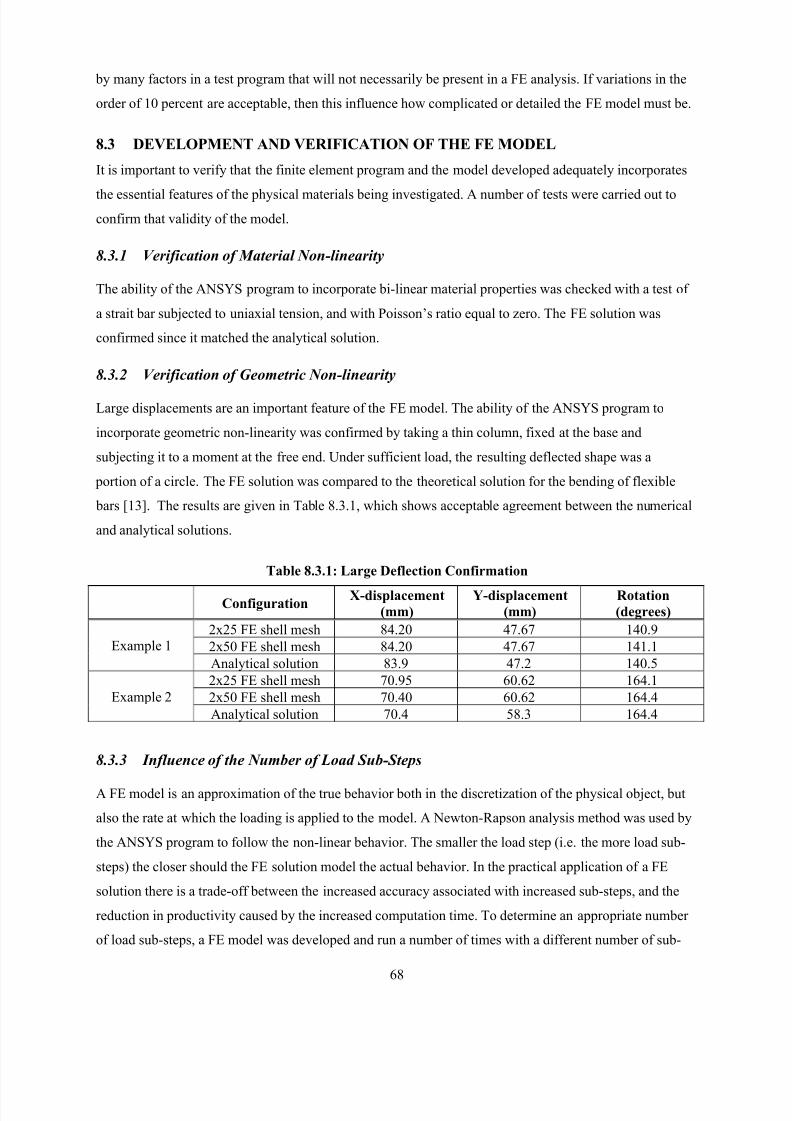
8/2/2019 Design of Bearing Stiffeners in Cold Formed C-Sections
http://slidepdf.com/reader/full/design-of-bearing-stiffeners-in-cold-formed-c-sections 82/151
68
by many factors in a test program that will not necessarily be present in a FE analysis. If variations in the
order of 10 percent are acceptable, then this influence how complicated or detailed the FE model must be.
8.3 DEVELOPMENT AND VERIFICATION OF THE FE MODEL
It is important to verify that the finite element program and the model developed adequately incorporates
the essential features of the physical materials being investigated. A number of tests were carried out to
confirm that validity of the model.
8.3.1 Verification of Material Non-linearity
The ability of the ANSYS program to incorporate bi-linear material properties was checked with a test of
a strait bar subjected to uniaxial tension, and with Poisson’s ratio equal to zero. The FE solution was
confirmed since it matched the analytical solution.
8.3.2 Verification of Geometric Non-linearity
Large displacements are an important feature of the FE model. The ability of the ANSYS program to
incorporate geometric non-linearity was confirmed by taking a thin column, fixed at the base and
subjecting it to a moment at the free end. Under sufficient load, the resulting deflected shape was a
portion of a circle. The FE solution was compared to the theoretical solution for the bending of flexible
bars [13]. The results are given in Table 8.3.1, which shows acceptable agreement between the numerical
and analytical solutions.
Table 8.3.1: Large Deflection Confirmation
ConfigurationX-displacement
(mm)
Y-displacement
(mm)
Rotation
(degrees)
2x25 FE shell mesh 84.20 47.67 140.9
2x50 FE shell mesh 84.20 47.67 141.1Example 1
Analytical solution 83.9 47.2 140.5
2x25 FE shell mesh 70.95 60.62 164.1
2x50 FE shell mesh 70.40 60.62 164.4Example 2
Analytical solution 70.4 58.3 164.4
8.3.3 Influence of the Number of Load Sub-Steps
A FE model is an approximation of the true behavior both in the discretization of the physical object, but
also the rate at which the loading is applied to the model. A Newton-Rapson analysis method was used by
the ANSYS program to follow the non-linear behavior. The smaller the load step (i.e. the more load sub-
steps) the closer should the FE solution model the actual behavior. In the practical application of a FE
solution there is a trade-off between the increased accuracy associated with increased sub-steps, and the
reduction in productivity caused by the increased computation time. To determine an appropriate number
of load sub-steps, a FE model was developed and run a number of times with a different number of sub-
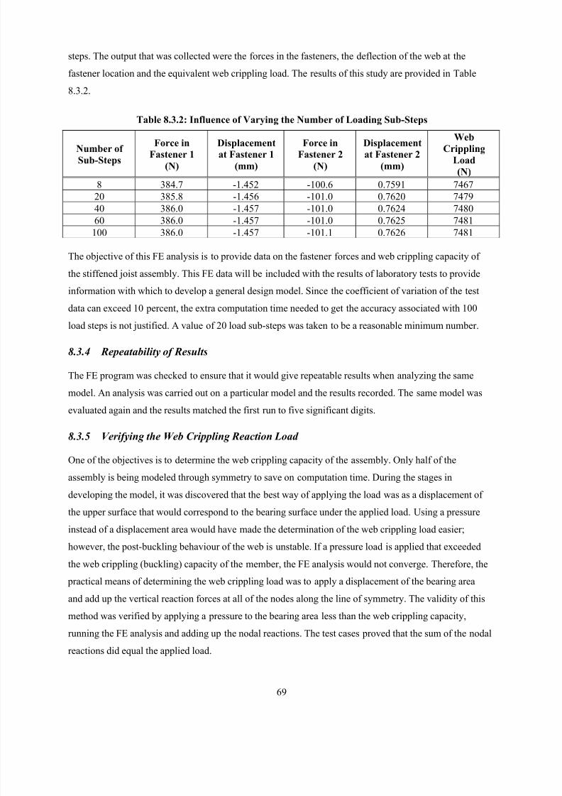
8/2/2019 Design of Bearing Stiffeners in Cold Formed C-Sections
http://slidepdf.com/reader/full/design-of-bearing-stiffeners-in-cold-formed-c-sections 83/151
69
steps. The output that was collected were the forces in the fasteners, the deflection of the web at the
fastener location and the equivalent web crippling load. The results of this study are provided in Table
8.3.2.
Table 8.3.2: Influence of Varying the Number of Loading Sub-Steps
Number of
Sub-Steps
Force in
Fastener 1
(N)
Displacement
at Fastener 1
(mm)
Force in
Fastener 2
(N)
Displacement
at Fastener 2
(mm)
WebCrippling
Load
(N)
8 384.7 -1.452 -100.6 0.7591 7467
20 385.8 -1.456 -101.0 0.7620 7479
40 386.0 -1.457 -101.0 0.7624 7480
60 386.0 -1.457 -101.0 0.7625 7481
100 386.0 -1.457 -101.1 0.7626 7481
The objective of this FE analysis is to provide data on the fastener forces and web crippling capacity of
the stiffened joist assembly. This FE data will be included with the results of laboratory tests to provideinformation with which to develop a general design model. Since the coefficient of variation of the test
data can exceed 10 percent, the extra computation time needed to get the accuracy associated with 100
load steps is not justified. A value of 20 load sub-steps was taken to be a reasonable minimum number.
8.3.4 Repeatability of Results
The FE program was checked to ensure that it would give repeatable results when analyzing the same
model. An analysis was carried out on a particular model and the results recorded. The same model was
evaluated again and the results matched the first run to five significant digits.
8.3.5 Verifying the Web Crippling Reaction Load
One of the objectives is to determine the web crippling capacity of the assembly. Only half of the
assembly is being modeled through symmetry to save on computation time. During the stages in
developing the model, it was discovered that the best way of applying the load was as a displacement of
the upper surface that would correspond to the bearing surface under the applied load. Using a pressure
instead of a displacement area would have made the determination of the web crippling load easier;
however, the post-buckling behaviour of the web is unstable. If a pressure load is applied that exceeded
the web crippling (buckling) capacity of the member, the FE analysis would not converge. Therefore, the
practical means of determining the web crippling load was to apply a displacement of the bearing area
and add up the vertical reaction forces at all of the nodes along the line of symmetry. The validity of this
method was verified by applying a pressure to the bearing area less than the web crippling capacity,
running the FE analysis and adding up the nodal reactions. The test cases proved that the sum of the nodal
reactions did equal the applied load.
8/2/2019 Design of Bearing Stiffeners in Cold Formed C-Sections
http://slidepdf.com/reader/full/design-of-bearing-stiffeners-in-cold-formed-c-sections 84/151
70
8.3.6 Effect of Varying the Tangent Modulus
The non-linear material properties of the joist material is modeled by a bi-linear stress-strain curve. The
initial elastic properties use a modulus of elasticity of 203 000 MPa, which is consistent with the current
design standards for cold formed steel. The tangent modulus after the yield point was measured from the
actual stress-strain curves of the material used in the laboratory tests, and with which the FE model was
being verified. A typical value of the tangent modulus was measured from the stress-strain curve to be
300 MPa. A study was done to determine the sensitivity of the FE model results to a change in the tangent
modulus. The results of this comparison are provided in Table 8.3.3.
Table 8.3.3: Influence of Varying the Tangent Modulus
Tangent
Modulus
(MPa)
Force in
Fastener 1
(N)
Displacement
at Fastener 1
(mm)
Force in
Fastener 2
(N)
Displacement
at Fastener 2
(mm)
Web
Crippling
Load
(N)
300 306 -0.86 -120 0.67 8130500 307 -0.86 -120 0.67 8160
1000 308 -0.86 -121 0.67 8260
2000 311 -0.87 -121 0.68 8440
5000 319 -0.89 -124 0.69 8930
10000 330 -0.92 -127 0.71 9614 Note: Model 12203e4, E=203000, Ef =14,800, t=1.21, Fy=332, Delta=0.5
The results show that a 10 times increase in the tangent modulus causes only a 10% increase in the web
crippling load. These findings justify the simplification of using a tangent modulus of 300 MPa for all
materials.
A similar study was carried out to determine if a multi-linear stress-strain model was warranted. An actual
stress-strain curve is very non-linear beyond the yield stress. This curvature would be better described by
a multi-linear model than a bi-linear model. A FEA was carried out on the same model but with the
following two different material properties:
(1) bi-linear model with E = 203 000, Fy = 332, Et = 300; and,
(2) multi-linear model with E = 203 000, Fy = 332, Et1 = 300, Fu = 400, Et2 = 10.
The results are provided in Table 8.3.4, and indicate that a multi-linear model is not necessary.
Table 8.3.4: Influence of a Multi-Linear Tangent Modulus
Tangent
Modulus
Force in
Fastener 1
(N)
Displacement
at Fastener 1
(mm)
Force in
Fastener 2
(N)
Displacement
at Fastener 2
(mm)
Web
Crippling
Load
(N)
Bi-linear 306 -0.86 -120 0.67 8130
Multi-linear 304 -0.85 -119 0.67 8000
8/2/2019 Design of Bearing Stiffeners in Cold Formed C-Sections
http://slidepdf.com/reader/full/design-of-bearing-stiffeners-in-cold-formed-c-sections 85/151
71
8.3.7 Fastener Flexibility
In early studies, the fasteners connecting the joist web to the stiffener were modeled as fixed degrees of
freedom at the nodes corresponding to the screw locations in the joist web. This assumption is not entirely
correct since the deformation of the joist web will put tension on the fastener, which in turn is connected
to the web of the stiffener. As the web buckles, the web deformation will be restrained by the fastener, but
the degree of restraint depends on the thickness and strength of the stiffener material.
Two lengths of stiffeners were used in the laboratory testing (203 and 305 mm, 8 and 12 in.) in two
thicknesses (0.85 and 1.50 mm, 0.033 and 0.059 in.). In addition, there were two types of fastener
arrangements (3v and 4h) as well as three fastener spacings (h/4, h/6 and h/12). These configurations are
illustrated in Figure 8.3.1. In all, 24 stiffener and fastener configurations were modeled.
Figure 8.3.1: FE Model for Determining Fastener Stiffness
The FE model of a typical stiffener is shown in Figure 8.3.1. The holes are 4 mm (5/32 in.) in diameter
corresponding to the size of a #10 self-drilling sheet metal screw. Loads were applied to the nodes around
the holes and the resulting deflections determined.
The flexibility of the fastener restraining the web is incorporated into the FE model of the joist by
including a link element perpendicular to the joist web, connected to the joist mesh at the node
representing the fastener, and fixed at its other end. The modulus of elasticity of this link was set to
correspond to the stiffness resulting from the load-deflection FE analysis.
8/2/2019 Design of Bearing Stiffeners in Cold Formed C-Sections
http://slidepdf.com/reader/full/design-of-bearing-stiffeners-in-cold-formed-c-sections 86/151
72
The following example describes how this link stiffness was determined:
1) Apply a load at screw location in FE model of stiffener of 2,400 N (540 lbs) (see Figure 4.7.1).
2) From the FE analysis, determine the average deflection of nodes around screw hole at maximum load
to be 8.1 mm (0.32 in.).
3) The length of FE link representing the screw is 50 mm and the area is 1 mm2.
4) The strain in FE link corresponding to the average deflection would be 8.1/50 = 0.162.
5) The stress in FE link corresponding to maximum load would be 2,400/1 = 2,400 N/mm2.
6) The equivalent stiffness of FE link would be 2,400/0.162 = 14,800 N/mm2.
The equivalent elastic modulus for each of the 24 stiffener configurations were calculated in this manner,
as summarized in Table 8.3.5.
Table 8.3.5: Equivalent Elastic Modulus Values for FE Links
Assembly Designation Equivalent Modulus(MPa)
Assembly Designation Equivalent Modulus(MPa)
3v1220e4 14,800 3v1216e4 29,600
3v820e4 13,900 3v816e4 38,500
4h1220e4 10,400 4h1216e4 32,000
4h820e4 13,800 4h816e4 49,500
3v1220e6 12,050 3v1216e6 32,920
3v820e6 14,800 3v816e6 41,240
4h1220e6 13,290 4h1216e6 41,030
4h820e6 16,260 4h816e6 52,290
3v1220e12 14,980 3v1216e12 42,330
3v820e12 17,320 3v816e12 53,330
4h1220e12 14,650 4h1216e12 49,6904h820e12 16,060 4h816e12 57,140
1 MPa = 0.145 ksi
A series of laboratory tests were conducted to verify the FE model of the fastener stiffness. The basic test
set-up is shown in Figure 8.3.2. A 305 mm (12 in.) length of stud representing the stiffener was clamping
in a universal testing machine. A #10 self-drilling sheet metal screw was installed at a location
corresponding to the location of a fastener in the FE model of the stiffened joist assembly. A bearing cap
was fixed on the end of the screw against which the actuator could push. A load cell and LVDT measured
the applied load and the resulting deflection of the screw. Three tests were conducted on two differentthicknesses of stiffener (0.88 and 1.19 mm, 0.035 and 0.047 in.). The load-deflection curves for each test
are given in Figure 8.3.3 and 8.3.4.
The purpose of doing these laboratory tests was to provide a comparison to the FE solution. Two FE
models were developed of the stiffener corresponding to the tested configurations. The FE analysis was
conducted and the resulting load-deflection relationship recorded. This data is also shown in Figures 8.3.3
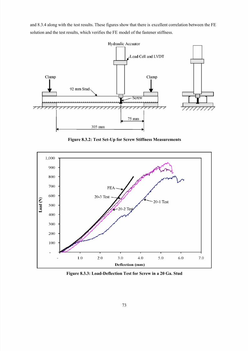
8/2/2019 Design of Bearing Stiffeners in Cold Formed C-Sections
http://slidepdf.com/reader/full/design-of-bearing-stiffeners-in-cold-formed-c-sections 87/151
73
and 8.3.4 along with the test results. These figures show that there is excellent correlation between the FE
solution and the test results, which verifies the FE model of the fastener stiffness.
Figure 8.3.2: Test Set-Up for Screw Stiffness Measurements
Figure 8.3.3: Load-Deflection Test for Screw in a 20 Ga. Stud
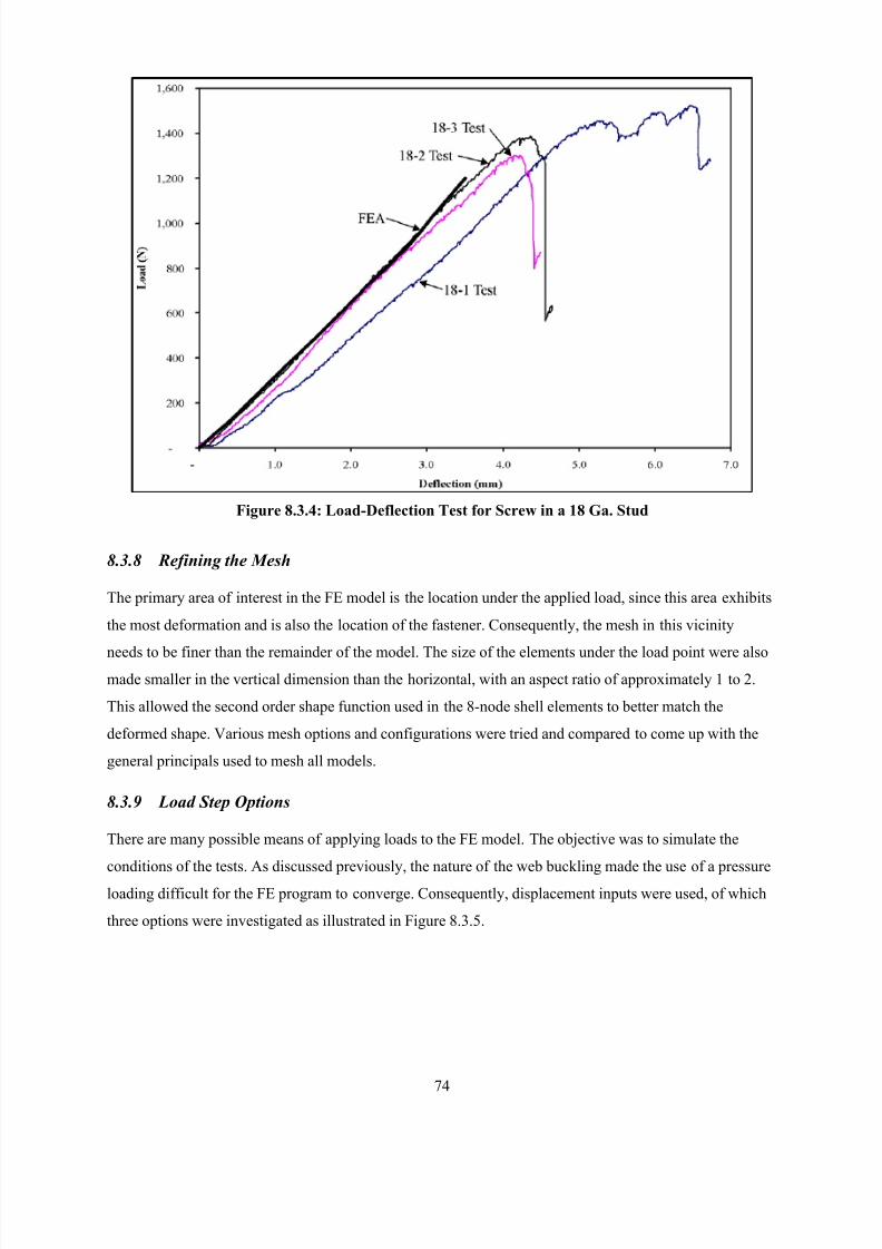
8/2/2019 Design of Bearing Stiffeners in Cold Formed C-Sections
http://slidepdf.com/reader/full/design-of-bearing-stiffeners-in-cold-formed-c-sections 88/151
74
Figure 8.3.4: Load-Deflection Test for Screw in a 18 Ga. Stud
8.3.8 Refining the Mesh
The primary area of interest in the FE model is the location under the applied load, since this area exhibits
the most deformation and is also the location of the fastener. Consequently, the mesh in this vicinity
needs to be finer than the remainder of the model. The size of the elements under the load point were alsomade smaller in the vertical dimension than the horizontal, with an aspect ratio of approximately 1 to 2.
This allowed the second order shape function used in the 8-node shell elements to better match the
deformed shape. Various mesh options and configurations were tried and compared to come up with the
general principals used to mesh all models.
8.3.9 Load Step Options
There are many possible means of applying loads to the FE model. The objective was to simulate the
conditions of the tests. As discussed previously, the nature of the web buckling made the use of a pressure
loading difficult for the FE program to converge. Consequently, displacement inputs were used, of which
three options were investigated as illustrated in Figure 8.3.5.
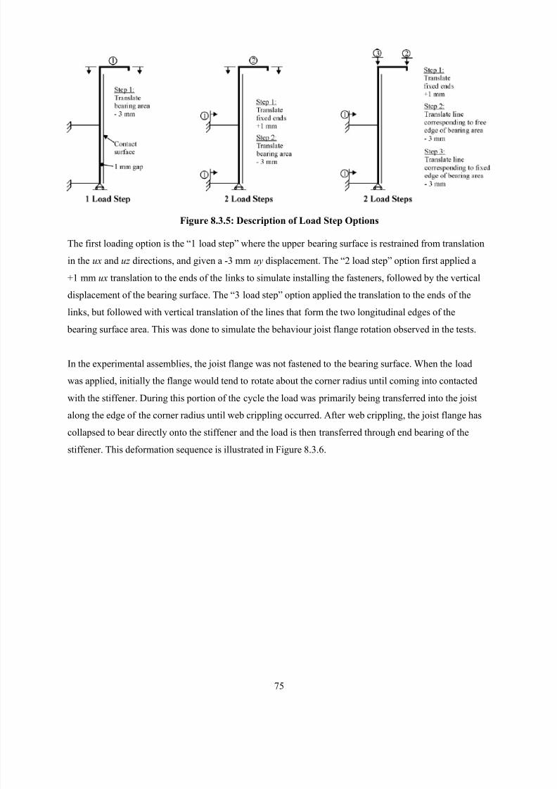
8/2/2019 Design of Bearing Stiffeners in Cold Formed C-Sections
http://slidepdf.com/reader/full/design-of-bearing-stiffeners-in-cold-formed-c-sections 89/151
75
Figure 8.3.5: Description of Load Step Options
The first loading option is the “1 load step” where the upper bearing surface is restrained from translation
in the ux and uz directions, and given a -3 mm uy displacement. The “2 load step” option first applied a
+1 mm ux translation to the ends of the links to simulate installing the fasteners, followed by the vertical
displacement of the bearing surface. The “3 load step” option applied the translation to the ends of the
links, but followed with vertical translation of the lines that form the two longitudinal edges of the
bearing surface area. This was done to simulate the behaviour joist flange rotation observed in the tests.
In the experimental assemblies, the joist flange was not fastened to the bearing surface. When the load
was applied, initially the flange would tend to rotate about the corner radius until coming into contacted
with the stiffener. During this portion of the cycle the load was primarily being transferred into the joist
along the edge of the corner radius until web crippling occurred. After web crippling, the joist flange has
collapsed to bear directly onto the stiffener and the load is then transferred through end bearing of the
stiffener. This deformation sequence is illustrated in Figure 8.3.6.
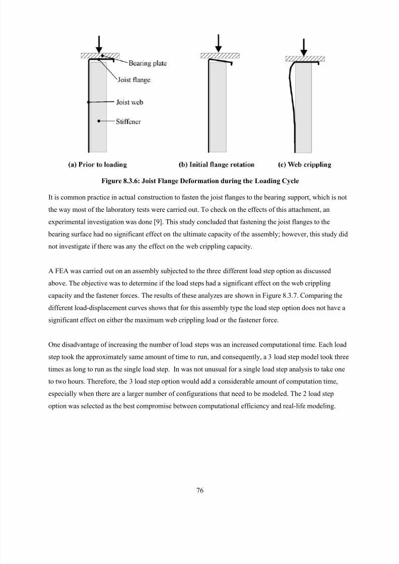
8/2/2019 Design of Bearing Stiffeners in Cold Formed C-Sections
http://slidepdf.com/reader/full/design-of-bearing-stiffeners-in-cold-formed-c-sections 90/151
76
Figure 8.3.6: Joist Flange Deformation during the Loading Cycle
It is common practice in actual construction to fasten the joist flanges to the bearing support, which is not
the way most of the laboratory tests were carried out. To check on the effects of this attachment, an
experimental investigation was done [9]. This study concluded that fastening the joist flanges to the
bearing surface had no significant effect on the ultimate capacity of the assembly; however, this study did
not investigate if there was any the effect on the web crippling capacity.
A FEA was carried out on an assembly subjected to the three different load step option as discussed
above. The objective was to determine if the load steps had a significant effect on the web crippling
capacity and the fastener forces. The results of these analyzes are shown in Figure 8.3.7. Comparing the
different load-displacement curves shows that for this assembly type the load step option does not have a
significant effect on either the maximum web crippling load or the fastener force.
One disadvantage of increasing the number of load steps was an increased computational time. Each load
step took the approximately same amount of time to run, and consequently, a 3 load step model took three
times as long to run as the single load step. In was not unusual for a single load step analysis to take one
to two hours. Therefore, the 3 load step option would add a considerable amount of computation time,
especially when there are a larger number of configurations that need to be modeled. The 2 load stepoption was selected as the best compromise between computational efficiency and real-life modeling.
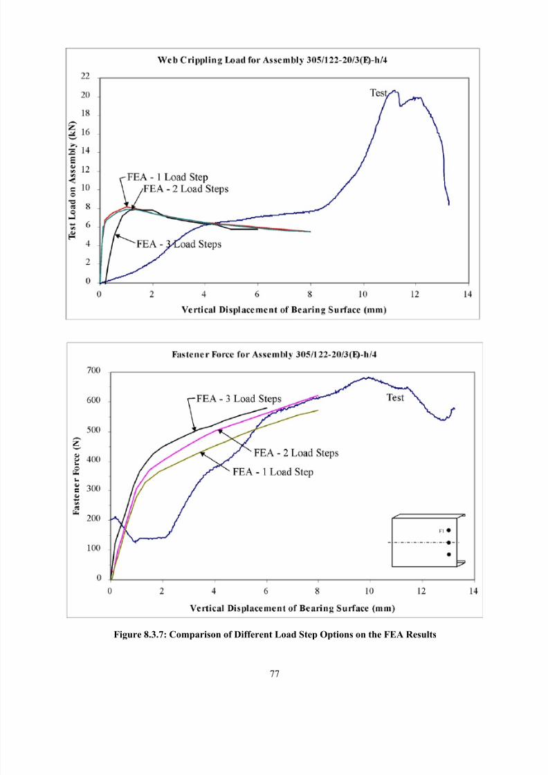
8/2/2019 Design of Bearing Stiffeners in Cold Formed C-Sections
http://slidepdf.com/reader/full/design-of-bearing-stiffeners-in-cold-formed-c-sections 91/151
77
Figure 8.3.7: Comparison of Different Load Step Options on the FEA Results
8/2/2019 Design of Bearing Stiffeners in Cold Formed C-Sections
http://slidepdf.com/reader/full/design-of-bearing-stiffeners-in-cold-formed-c-sections 92/151
78
8.4 COMPARISONS OF FEA MODEL WITH TEST DATA
8.4.1 Measuring the Web Crippling Loads and Fastener Forces by Test
One of the key objectives of the FE study is to develop a numerical model that can reasonably predict the
web crippling capacity of a joist with a bearing stiffener. In order to verify that the FE model is providingacceptable results, a series of laboratory tests were carried out [19] that measured the load-deflection
characteristics of various stiffened joist assemblies. The details of these tests were presented in Section 5.
8.4.2 Comparing the FEA and Tested Load-Deflection Curves
The results of the FE solution were compared to the load deflection curves measured in the laboratory
tests. Figures 8.4.1, 8.4.2, 8.4.3 and 8.4.4 provide some representative comparisons.
The FE results for the web crippling capacity were generally higher that the tested values. This can be due
to a number of causes.
1. The discretization of the assembly in the FE process will naturally yield a stiffer model than the
actual specimen. If a finer FE mesh were used this difference could be reduced, but at the cost of
added computational time.
2. The FE model does not take into account the many initial imperfections that are present in the
physical model. Initial imperfections could be built into the FE model, but the imperfections
present in a physical model could not be completely predicted.
3. The FE model does not accurately model the initial flange rotation of the joist prior to web
crippling. This rotation will have the effect of applying an initial curvature to the joist web, which
would reduce the buckling capacity.
4. The FEA also does not model the test specimen having two separate joist members loaded
simultaneously. The test set-up endeavored to load the assembly symmetrically, but no
measurement was made of the load carried by each individual joist. Consequently, it is likely that
the load would not be perfected distributed and one joist would be carrying more of the load than
the other. This would tend to precipitate a failure in the joist with the higher load, and lead to a
lower average load for the pair than would be the case if the load was equally divided between the
two specimens.
The plots of the FE and tested web crippling loads in Figures 8.4.1 through 8.4.4, are similar in shape to
column buckling curves with different degrees of initial imperfections. As the imperfections increase, the
load-deflection curve develops a more rounded shape. This phenomenon is consistent with the earlier
discussion about the differences between the FE model and the physical model. Even though the FE
8/2/2019 Design of Bearing Stiffeners in Cold Formed C-Sections
http://slidepdf.com/reader/full/design-of-bearing-stiffeners-in-cold-formed-c-sections 93/151
79
solution will normally yield higher ultimate loads, the results are still useful as long as they are consistent
and calibrated to the test data.
The plots in Figures 8.4.1 through 8.4.4 show that the fastener forces predicted by the FE analysis
generally agree with the test results both in the magnitude and general shape of the load-deflection curves.
There are, however, a number of variables in the physical test that are not included in the FE analysis.1. When the screws were installed they were given an initial pre-load that would correspond to the
clamping force generated during the normal screw installation. The load-deflection curves for the
tests shown in the figures all start from a load corresponding to this pre-load. The attached load
cell will not begin to record any additional load until the force generated in the fastener, as a
result of web buckling, has exceeded the pre-load amount. In the three-screw configurations
illustrated in Figure 5.3.1, the screw at the centre of the joist does not carry any additional load
since the deformation of the joist web is towards the stiffener, not away from it.
2. In order for the load cell under the screw head to measure any force, a pilot hole was drilled in the joist web that was larger than the diameter of the screw but smaller than the diameter of the load
cell. This created a situation where the clamping action between the stiffener and the joist web
was transferred through the load cell. While this allowed the measurement of the screw force, it
also changed the buckling behavior of the joist web. The hole around the screw allowed the joist
web to move slightly relative to the stiffener, which would have an effect of changing the stress
distribution. This phenomenon was most apparent when the fasteners were located nearest the
flange (i.e. h/12).
The comparisons of the FE and test load-deflection curves agree sufficiently to provide a degree of
confidence in the numerical solution within the limitations to be discussed later in section 8.4.6.
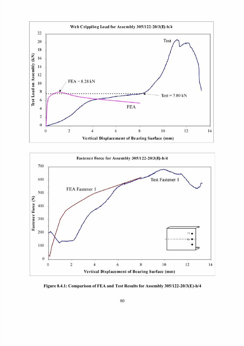
8/2/2019 Design of Bearing Stiffeners in Cold Formed C-Sections
http://slidepdf.com/reader/full/design-of-bearing-stiffeners-in-cold-formed-c-sections 94/151
80
Figure 8.4.1: Comparison of FEA and Test Results for Assembly 305/122-20/3(E)-h/4
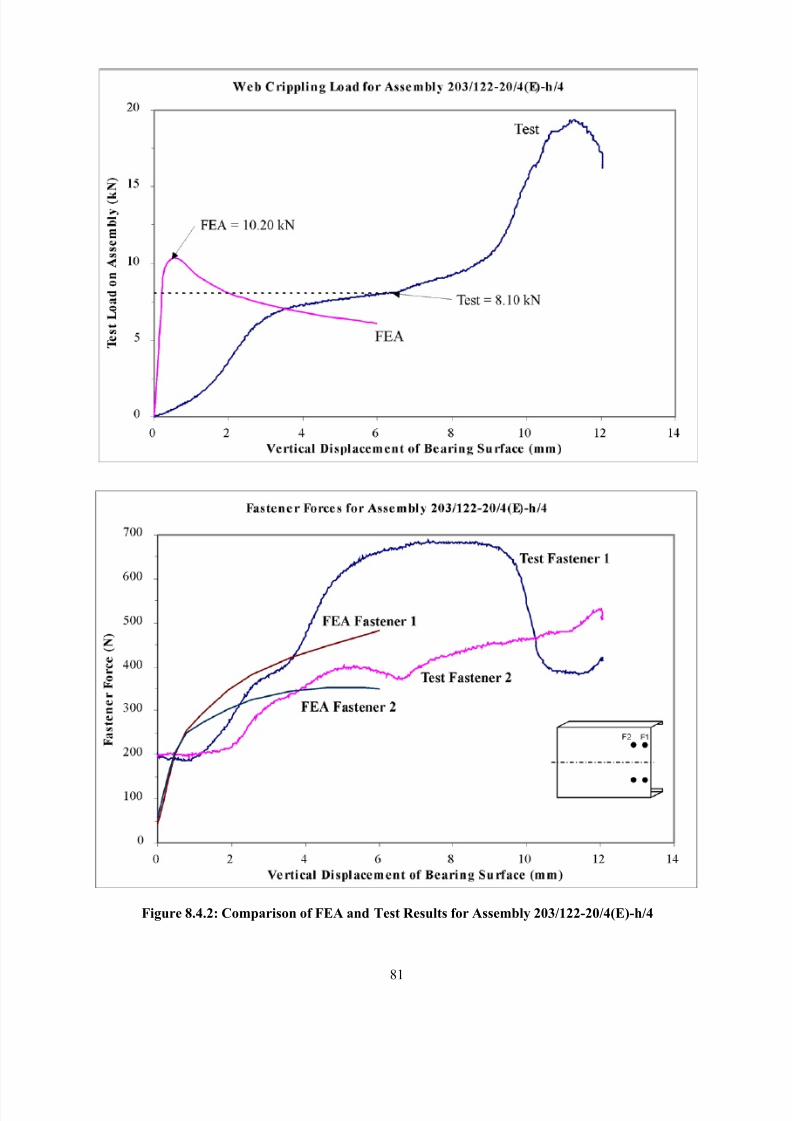
8/2/2019 Design of Bearing Stiffeners in Cold Formed C-Sections
http://slidepdf.com/reader/full/design-of-bearing-stiffeners-in-cold-formed-c-sections 95/151
81
Figure 8.4.2: Comparison of FEA and Test Results for Assembly 203/122-20/4(E)-h/4
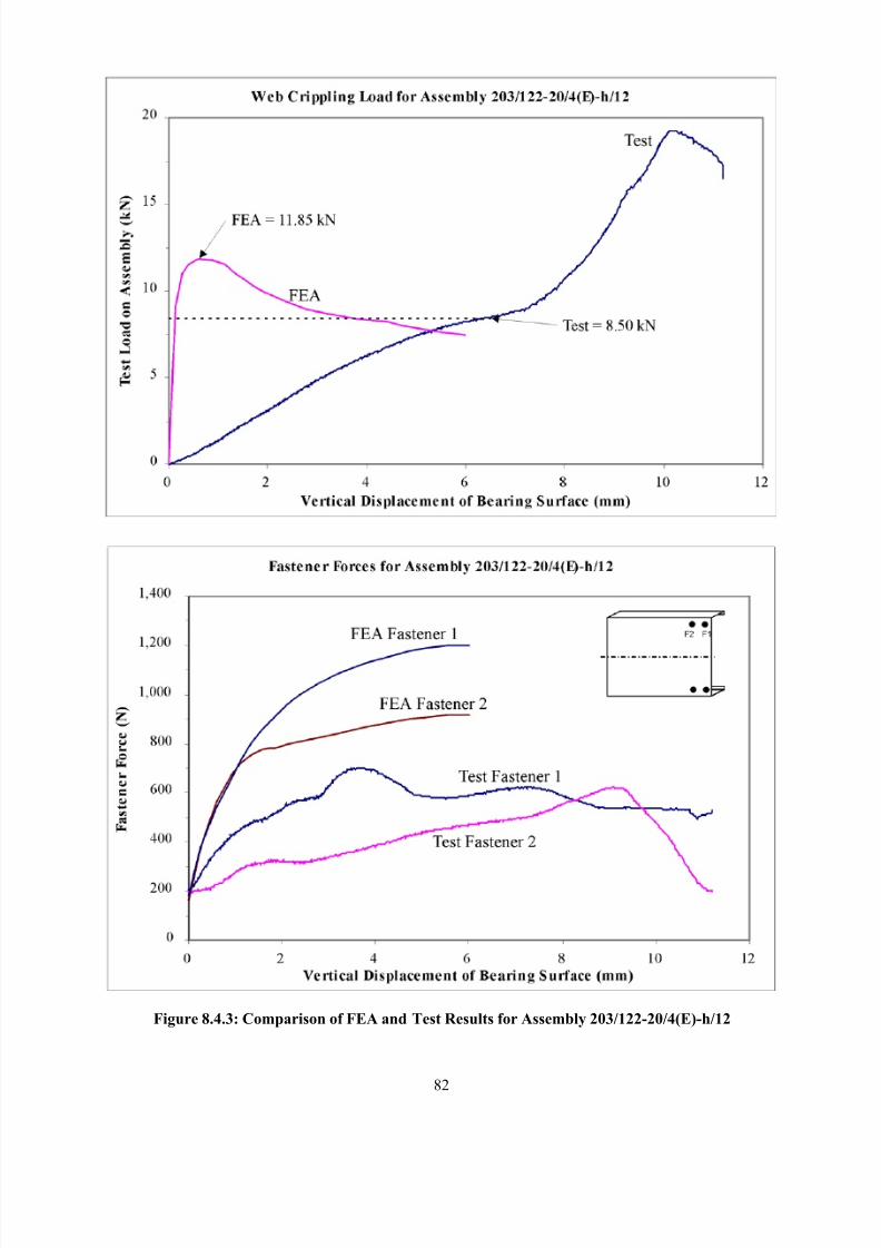
8/2/2019 Design of Bearing Stiffeners in Cold Formed C-Sections
http://slidepdf.com/reader/full/design-of-bearing-stiffeners-in-cold-formed-c-sections 96/151
82
Figure 8.4.3: Comparison of FEA and Test Results for Assembly 203/122-20/4(E)-h/12
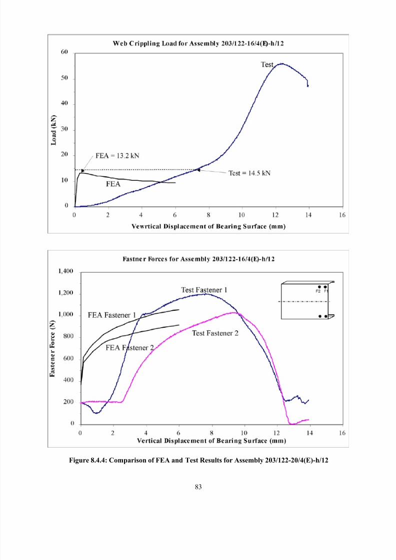
8/2/2019 Design of Bearing Stiffeners in Cold Formed C-Sections
http://slidepdf.com/reader/full/design-of-bearing-stiffeners-in-cold-formed-c-sections 97/151
83
Figure 8.4.4: Comparison of FEA and Test Results for Assembly 203/122-20/4(E)-h/12
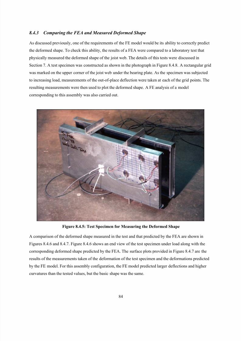
8/2/2019 Design of Bearing Stiffeners in Cold Formed C-Sections
http://slidepdf.com/reader/full/design-of-bearing-stiffeners-in-cold-formed-c-sections 98/151
84
8.4.3 Comparing the FEA and Measured Deformed Shape
As discussed previously, one of the requirements of the FE model would be its ability to correctly predict
the deformed shape. To check this ability, the results of a FEA were compared to a laboratory test that
physically measured the deformed shape of the joist web. The details of this tests were discussed inSection 7. A test specimen was constructed as shown in the photograph in Figure 8.4.8. A rectangular grid
was marked on the upper corner of the joist web under the bearing plate. As the specimen was subjected
to increasing load, measurements of the out-of-place deflection were taken at each of the grid points. The
resulting measurements were then used to plot the deformed shape. A FE analysis of a model
corresponding to this assembly was also carried out.
Figure 8.4.5: Test Specimen for Measuring the Deformed Shape
A comparison of the deformed shape measured in the test and that predicted by the FEA are shown in
Figures 8.4.6 and 8.4.7. Figure 8.4.6 shows an end view of the test specimen under load along with the
corresponding deformed shape predicted by the FEA. The surface plots provided in Figure 8.4.7 are the
results of the measurements taken of the deformation of the test specimen and the deformations predicted
by the FE model. For this assembly configuration, the FE model predicted larger deflections and higher
curvatures than the tested values, but the basic shape was the same.
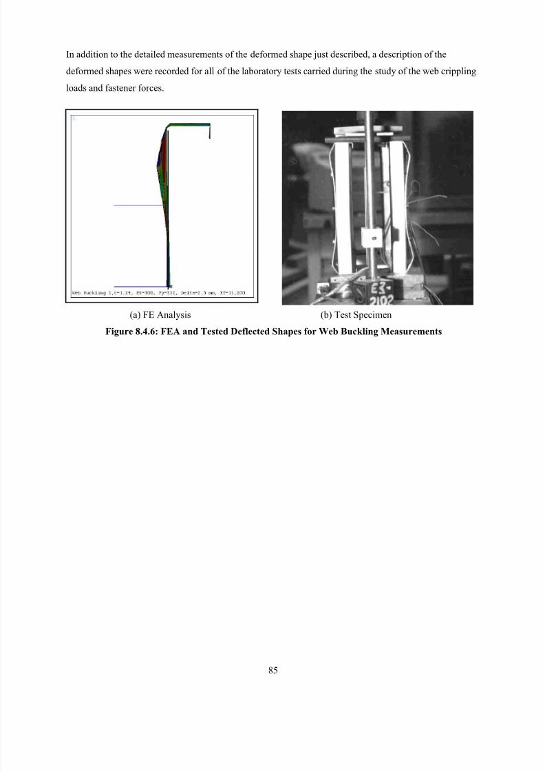
8/2/2019 Design of Bearing Stiffeners in Cold Formed C-Sections
http://slidepdf.com/reader/full/design-of-bearing-stiffeners-in-cold-formed-c-sections 99/151
85
In addition to the detailed measurements of the deformed shape just described, a description of the
deformed shapes were recorded for all of the laboratory tests carried during the study of the web crippling
loads and fastener forces.
(a) FE Analysis (b) Test Specimen
Figure 8.4.6: FEA and Tested Deflected Shapes for Web Buckling Measurements
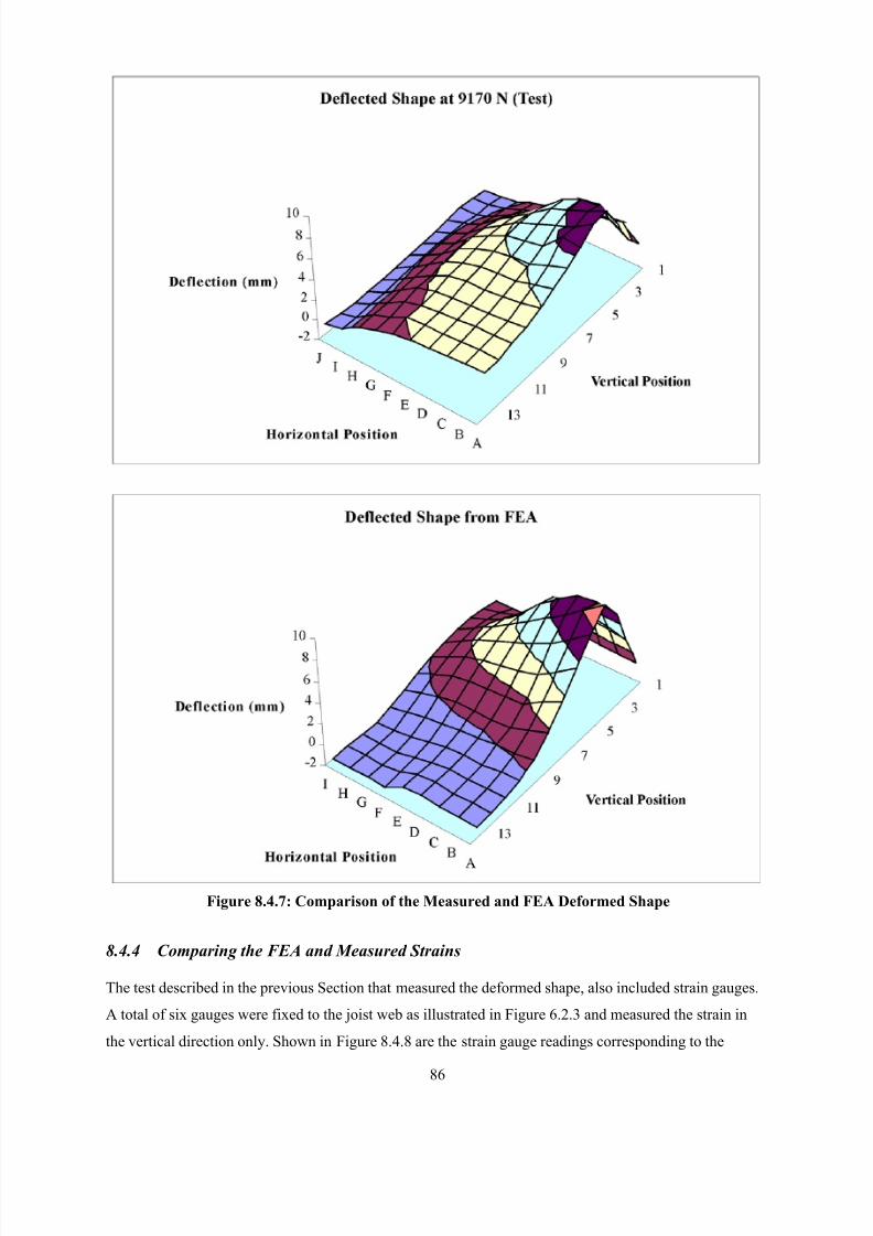
8/2/2019 Design of Bearing Stiffeners in Cold Formed C-Sections
http://slidepdf.com/reader/full/design-of-bearing-stiffeners-in-cold-formed-c-sections 100/151
86
Figure 8.4.7: Comparison of the Measured and FEA Deformed Shape
8.4.4 Comparing the FEA and Measured Strains
The test described in the previous Section that measured the deformed shape, also included strain gauges.
A total of six gauges were fixed to the joist web as illustrated in Figure 6.2.3 and measured the strain in
the vertical direction only. Shown in Figure 8.4.8 are the strain gauge readings corresponding to the
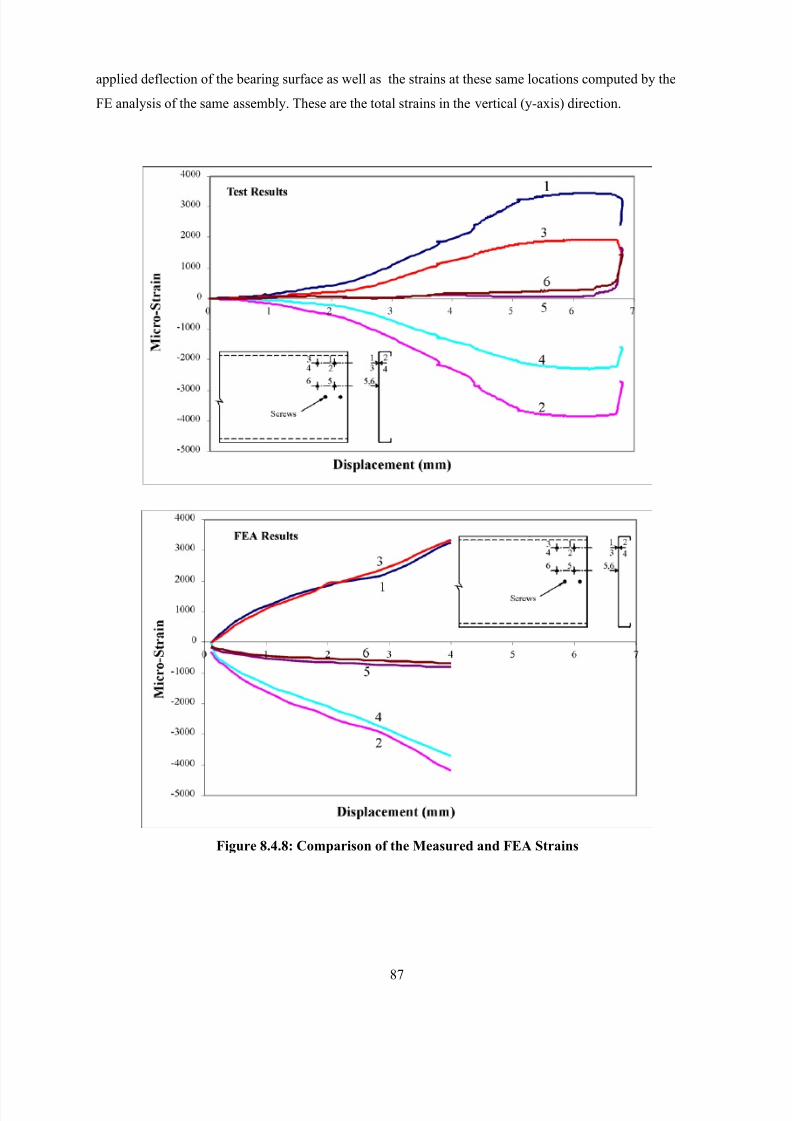
8/2/2019 Design of Bearing Stiffeners in Cold Formed C-Sections
http://slidepdf.com/reader/full/design-of-bearing-stiffeners-in-cold-formed-c-sections 101/151
87
applied deflection of the bearing surface as well as the strains at these same locations computed by the
FE analysis of the same assembly. These are the total strains in the vertical (y-axis) direction.
Figure 8.4.8: Comparison of the Measured and FEA Strains
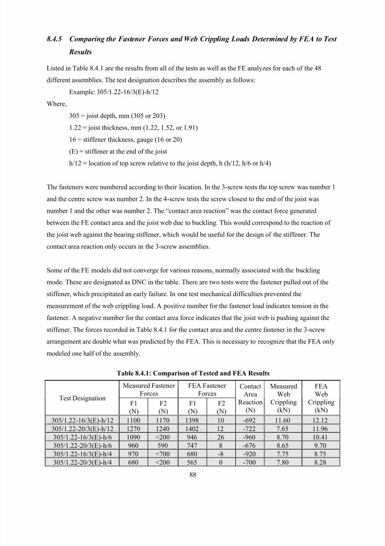
8/2/2019 Design of Bearing Stiffeners in Cold Formed C-Sections
http://slidepdf.com/reader/full/design-of-bearing-stiffeners-in-cold-formed-c-sections 102/151
88
8.4.5 Comparing the Fastener Forces and Web Crippling Loads Determined by FEA to Test
Results
Listed in Table 8.4.1 are the results from all of the tests as well as the FE analyzes for each of the 48
different assemblies. The test designation describes the assembly as follows:
Example: 305/1.22-16/3(E)-h/12
Where,
305 = joist depth, mm (305 or 203)
1.22 = joist thickness, mm (1.22, 1.52, or 1.91)
16 = stiffener thickness, gauge (16 or 20)
(E) = stiffener at the end of the joist
h/12 = location of top screw relative to the joist depth, h (h/12, h/6 or h/4)
The fasteners were numbered according to their location. In the 3-screw tests the top screw was number 1
and the centre screw was number 2. In the 4-screw tests the screw closest to the end of the joist was
number 1 and the other was number 2. The “contact area reaction” was the contact force generated
between the FE contact area and the joist web due to buckling. This would correspond to the reaction of
the joist web against the bearing stiffener, which would be useful for the design of the stiffener. The
contact area reaction only occurs in the 3-screw assemblies.
Some of the FE models did not converge for various reasons, normally associated with the buckling
mode. These are designated as DNC in the table. There are two tests were the fastener pulled out of the
stiffener, which precipitated an early failure. In one test mechanical difficulties prevented the
measurement of the web crippling load. A positive number for the fastener load indicates tension in the
fastener. A negative number for the contact area force indicates that the joist web is pushing against the
stiffener. The forces recorded in Table 8.4.1 for the contact area and the centre fastener in the 3-screw
arrangement are double what was predicted by the FEA. This is necessary to recognize that the FEA only
modeled one half of the assembly.
Table 8.4.1: Comparison of Tested and FEA Results
Measured Fastener
Forces
FEA Fastener
ForcesTest Designation
F1
(N)
F2
(N)
F1
(N)
F2
(N)
Contact
Area
Reaction
(N)
Measured
Web
Crippling
(kN)
FEA
Web
Crippling
(kN)
305/1.22-16/3(E)-h/12 1100 1170 1398 10 -692 11.60 12.12
305/1.22-20/3(E)-h/12 1270 1240 1402 12 -722 7.65 11.96
305/1.22-16/3(E)-h/6 1090 <200 946 26 -960 8.70 10.41
305/1.22-20/3(E)-h/6 960 590 747 8 -676 8.65 9.70
305/1.22-16/3(E)-h/4 970 <700 680 -8 -920 7.75 8.75
305/1.22-20/3(E)-h/4 680 <200 565 0 -700 7.80 8.28
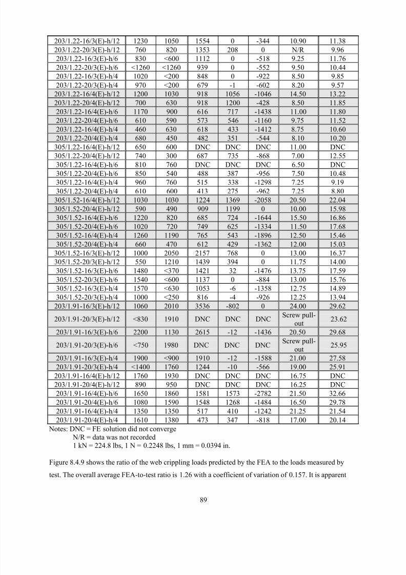
8/2/2019 Design of Bearing Stiffeners in Cold Formed C-Sections
http://slidepdf.com/reader/full/design-of-bearing-stiffeners-in-cold-formed-c-sections 103/151
89
203/1.22-16/3(E)-h/12 1230 1050 1554 0 -344 10.90 11.38
203/1.22-20/3(E)-h/12 760 820 1353 208 0 N/R 9.96
203/1.22-16/3(E)-h/6 830 <600 1112 0 -518 9.25 11.76
203/1.22-20/3(E)-h/6 <1260 <1260 939 0 -552 9.50 10.44
203/1.22-16/3(E)-h/4 1020 <200 848 0 -922 8.50 9.85
203/1.22-20/3(E)-h/4 970 <200 679 -1 -602 8.20 9.57
203/1.22-16/4(E)-h/12 1200 1030 918 1056 -1046 14.50 13.22
203/1.22-20/4(E)-h/12 700 630 918 1200 -428 8.50 11.85
203/1.22-16/4(E)-h/6 1170 900 616 717 -1438 11.00 11.80
203/1.22-20/4(E)-h/6 610 590 573 546 -1160 9.75 11.52
203/1.22-16/4(E)-h/4 460 630 618 433 -1412 8.75 10.60
203/1.22-20/4(E)-h/4 680 450 482 351 -544 8.10 10.20
305/1.22-16/4(E)-h/12 650 600 DNC DNC DNC 11.00 DNC
305/1.22-20/4(E)-h/12 740 300 687 735 -868 7.00 12.55
305/1.22-16/4(E)-h/6 810 760 DNC DNC DNC 6.50 DNC
305/1.22-20/4(E)-h/6 850 540 488 387 -956 7.50 10.48
305/1.22-16/4(E)-h/4 960 760 515 338 -1298 7.25 9.19
305/1.22-20/4(E)-h/4 610 600 413 275 -962 7.25 8.80
305/1.52-16/4(E)-h/12 1030 1030 1224 1369 -2058 20.50 22.04305/1.52-20/4(E)-h/12 590 490 909 1199 0 10.00 15.98
305/1.52-16/4(E)-h/6 1220 820 685 724 -1644 15.50 16.86
305/1.52-20/4(E)-h/6 1020 720 749 625 -1334 11.50 17.68
305/1.52-16/4(E)-h/4 1260 1190 765 543 -1896 12.50 15.46
305/1.52-20/4(E)-h/4 660 470 612 429 -1362 12.00 15.03
305/1.52-16/3(E)-h/12 1000 2050 2157 768 0 13.00 16.37
305/1.52-20/3(E)-h/12 550 1210 1439 394 0 11.75 14.00
305/1.52-16/3(E)-h/6 1480 <370 1421 32 -1476 13.75 17.59
305/1.52-20/3(E)-h/6 1540 <600 1137 0 -884 13.00 15.76
305/1.52-16/3(E)-h/4 1570 <630 1053 -6 -1358 12.75 14.89
305/1.52-20/3(E)-h/4 1000 <250 816 -4 -926 12.25 13.94
203/1.91-16/3(E)-h/12 1060 2010 3536 -802 0 24.00 29.62
203/1.91-20/3(E)-h/12 <830 1910 DNC DNC DNCScrew pull-
out23.62
203/1.91-16/3(E)-h/6 2200 1130 2615 -12 -1436 20.50 29.68
203/1.91-20/3(E)-h/6 <750 1980 DNC DNC DNCScrew pull-
out25.95
203/1.91-16/3(E)-h/4 1900 <900 1910 -12 -1588 21.00 27.58
203/1.91-20/3(E)-h/4 <1400 1760 1244 -10 -566 19.00 25.91
203/1.91-16/4(E)-h/12 1760 1930 DNC DNC DNC 16.75 DNC
203/1.91-20/4(E)-h/12 890 950 DNC DNC DNC 16.25 DNC
203/1.91-16/4(E)-h/6 1650 1860 1581 1573 -2782 21.50 32.66
203/1.91-20/4(E)-h/6 1080 1590 1548 1268 -1484 16.50 29.78203/1.91-16/4(E)-h/4 1350 1350 517 410 -1242 21.25 21.54
203/1.91-20/4(E)-h/4 1610 1380 473 347 -818 17.00 20.14
Notes: DNC = FE solution did not converge
N/R = data was not recorded
1 kN = 224.8 lbs, 1 N = 0.2248 lbs, 1 mm = 0.0394 in.
Figure 8.4.9 shows the ratio of the web crippling loads predicted by the FEA to the loads measured by
test. The overall average FEA-to-test ratio is 1.26 with a coefficient of variation of 0.157. It is apparent
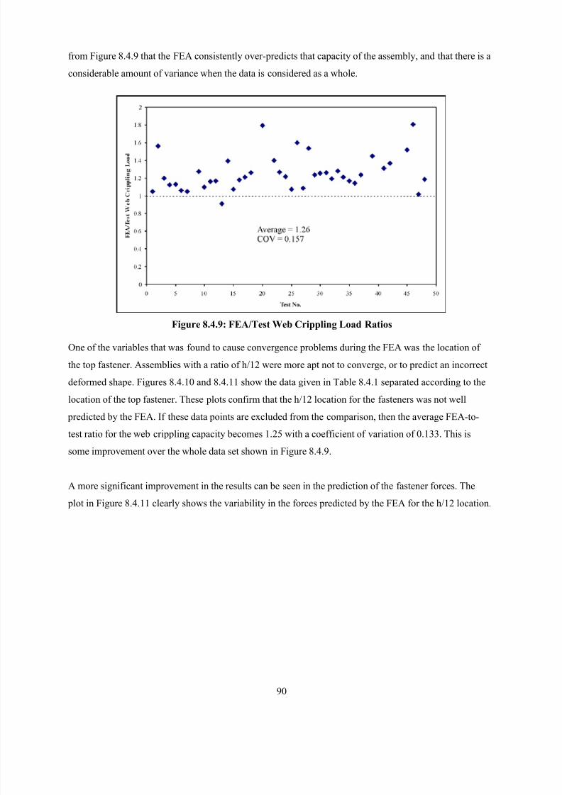
8/2/2019 Design of Bearing Stiffeners in Cold Formed C-Sections
http://slidepdf.com/reader/full/design-of-bearing-stiffeners-in-cold-formed-c-sections 104/151
90
from Figure 8.4.9 that the FEA consistently over-predicts that capacity of the assembly, and that there is a
considerable amount of variance when the data is considered as a whole.
Figure 8.4.9: FEA/Test Web Crippling Load Ratios
One of the variables that was found to cause convergence problems during the FEA was the location of
the top fastener. Assemblies with a ratio of h/12 were more apt not to converge, or to predict an incorrect
deformed shape. Figures 8.4.10 and 8.4.11 show the data given in Table 8.4.1 separated according to the
location of the top fastener. These plots confirm that the h/12 location for the fasteners was not well
predicted by the FEA. If these data points are excluded from the comparison, then the average FEA-to-
test ratio for the web crippling capacity becomes 1.25 with a coefficient of variation of 0.133. This is
some improvement over the whole data set shown in Figure 8.4.9.
A more significant improvement in the results can be seen in the prediction of the fastener forces. The
plot in Figure 8.4.11 clearly shows the variability in the forces predicted by the FEA for the h/12 location.
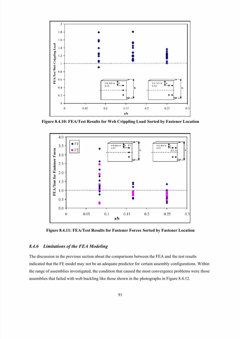
8/2/2019 Design of Bearing Stiffeners in Cold Formed C-Sections
http://slidepdf.com/reader/full/design-of-bearing-stiffeners-in-cold-formed-c-sections 105/151
91
Figure 8.4.10: FEA/Test Results for Web Crippling Load Sorted by Fastener Location
Figure 8.4.11: FEA/Test Results for Fastener Forces Sorted by Fastener Location
8.4.6 Limitations of the FEA Modeling
The discussion in the previous section about the comparisons between the FEA and the test results
indicated that the FE model may not be an adequate predictor for certain assembly configurations. Within
the range of assemblies investigated, the condition that caused the most convergence problems were those
assemblies that failed with web buckling like those shown in the photographs in Figure 8.4.12.
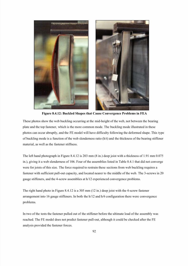
8/2/2019 Design of Bearing Stiffeners in Cold Formed C-Sections
http://slidepdf.com/reader/full/design-of-bearing-stiffeners-in-cold-formed-c-sections 106/151
92
Figure 8.4.12: Buckled Shapes that Cause Convergence Problems in FEA
These photos show the web buckling occurring at the mid-height of the web, not between the bearing
plate and the top fastener, which is the more common mode. The buckling mode illustrated in these
photos can occur abruptly, and the FE model will have difficulty following the deformed shape. This type
of buckling mode is a function of the web slenderness ratio (h/t) and the thickness of the bearing stiffener material, as well as the fastener stiffness.
The left hand photograph in Figure 8.4.12 is 203 mm (8 in.) deep joist with a thickness of 1.91 mm 0.075
in.), giving it a web slenderness of 106. Four of the assemblies listed in Table 8.4.1 that did not converge
were for joists of this size. The force required to restrain these sections from web buckling requires a
fastener with sufficient pull-out capacity, and located nearer to the middle of the web. The 3-screws in 20
gauge stiffeners, and the 4-screw assemblies at h/12 experienced convergence problems.
The right hand photo in Figure 8.4.12 is a 305 mm (12 in.) deep joist with the 4-screw fastener
arrangement into 16 gauge stiffeners. In both the h/12 and h/6 configuration there were convergence
problems.
In two of the tests the fastener pulled out of the stiffener before the ultimate load of the assembly was
reached. The FE model does not predict fastener pull-out, although it could be checked after the FE
analysis provided the fastener forces.
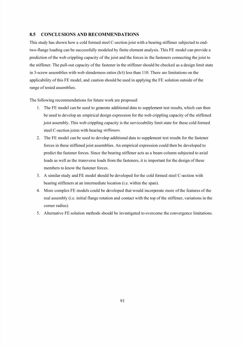
8/2/2019 Design of Bearing Stiffeners in Cold Formed C-Sections
http://slidepdf.com/reader/full/design-of-bearing-stiffeners-in-cold-formed-c-sections 107/151
93
8.5 CONCLUSIONS AND RECOMMENDATIONS
This study has shown how a cold formed steel C-section joist with a bearing stiffener subjected to end-
two-flange loading can be successfully modeled by finite element analysis. This FE model can provide a
prediction of the web crippling capacity of the joist and the forces in the fasteners connecting the joist to
the stiffener. The pull-out capacity of the fastener in the stiffener should be checked as a design limit state
in 3-screw assemblies with web slenderness ratios (h/t) less than 110. There are limitations on the
applicability of this FE model, and caution should be used in applying the FE solution outside of the
range of tested assemblies.
The following recommendations for future work are proposed:
1. The FE model can be used to generate additional data to supplement test results, which can then
be used to develop an empirical design expression for the web crippling capacity of the stiffened
joist assembly. This web crippling capacity is the serviceability limit state for these cold formed
steel C-section joists with bearing stiffeners.
2. The FE model can be used to develop additional data to supplement test results for the fastener
forces in these stiffened joist assemblies. An empirical expression could then be developed to
predict the fastener forces. Since the bearing stiffener acts as a beam column subjected to axial
loads as well as the transverse loads from the fasteners, it is important for the design of these
members to know the fastener forces.
3. A similar study and FE model should be developed for the cold formed steel C-section with
bearing stiffeners at an intermediate location (i.e. within the span).
4. More complex FE models could be developed that would incorporate more of the features of the
real assembly (i.e. initial flange rotation and contact with the top of the stiffener, variations in the
corner radius).
5. Alternative FE solution methods should be investigated to overcome the convergence limitations.
8/2/2019 Design of Bearing Stiffeners in Cold Formed C-Sections
http://slidepdf.com/reader/full/design-of-bearing-stiffeners-in-cold-formed-c-sections 108/151
94
9 ANALYSIS OF TEST RESULTS
9.1 COMPARISON OF VARIOUS PREDICTOR METHODS TO TEST RESULTS
Described in this section are comparisons of various predictor methods used to model the test results.
9.2 CURRENT AISI METHOD
The current AISI method was described in Section 2.2. This method assumes that the stiffener is fully
effective and that a portion of the joist web acts together with the stiffener to carry the load. This method
does not apply to the stud and track stiffeners since these members are not fully effective; however, the
channel stiffeners do meet the requirements of the Specification and should be designed accordingly.
Only a limited number of tests were carried out on the channel stiffeners since these types of sections
were not the primary focus of this research effort. The channels were tested to provide a comparison to
the capacities predicted by the current Specification. The summary of the test-to-predicted ratios are
reported in Table 9.2.1 and illustrated in Figure 9.2.1. Only tests with the stiffener at the end location
were carried out.
Table 9.2.1: Test-to-Predicted Results for the AISI Method with Channel Stiffeners
Configuration No. of TestsMean Test-to-
PredictedC.O.V.
Track-End-Inside 16 0.59 0.236
Track-End-Outside 12 0.74 0.096
Figure 9.2.1: Plots of the Test-to-Predicted Ratios for the AISI Method with Channel Stiffeners
The results would indicated that the current design method over-estimates the capacity of these sections,
particularly for the end-inside configuration. The differences between the tested capacities and those
predicted by the Specification can be attributed to the following factors:
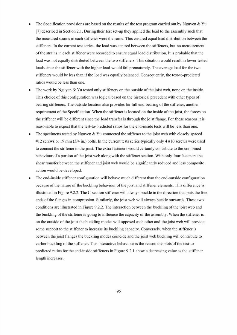
8/2/2019 Design of Bearing Stiffeners in Cold Formed C-Sections
http://slidepdf.com/reader/full/design-of-bearing-stiffeners-in-cold-formed-c-sections 109/151
95
• The Specification provisions are based on the results of the test program carried out by Nguyen & Yu
[7] described in Section 2.1. During their test set-up they applied the load to the assembly such that
the measured strains in each stiffener were the same. This ensured equal load distribution between the
stiffeners. In the current test series, the load was centred between the stiffeners, but no measurement
of the strains in each stiffener were recorded to ensure equal load distribution. It is probable that the
load was not equally distributed between the two stiffeners. This situation would result in lower tested
loads since the stiffener with the higher load would fail prematurely. The average load for the two
stiffeners would be less than if the load was equally balanced. Consequently, the test-to-predicted
ratios would be less than one.
• The work by Nguyen & Yu tested only stiffeners on the outside of the joist web, none on the inside.
This choice of this configuration was logical based on the historical precedent with other types of
bearing stiffeners. The outside location also provides for full end bearing of the stiffener, another
requirement of the Specification. When the stiffener is located on the inside of the joist, the forces on
the stiffener will be different since the load transfer is through the joist flange. For these reasons it is
reasonable to expect that the test-to-predicted ratios for the end-inside tests will be less than one.
• The specimens tested by Nguyen & Yu connected the stiffener to the joist web with closely spaced
#12 screws or 19 mm (3/4 in.) bolts. In the current tests series typically only 4 #10 screws were used
to connect the stiffener to the joist. The extra fasteners would certainly contribute to the combined
behaviour of a portion of the joist web along with the stiffener section. With only four fasteners the
shear transfer between the stiffener and joist web would be significantly reduced and less composite
action would be developed.
• The end-inside stiffener configuration will behave much different than the end-outside configuration
because of the nature of the buckling behaviour of the joist and stiffener elements. This difference is
illustrated in Figure 9.2.2. The C-section stiffener will always buckle in the direction that puts the free
ends of the flanges in compression. Similarly, the joist web will always buckle outwards. These two
conditions are illustrated in Figure 9.2.2. The interaction between the buckling of the joist web and
the buckling of the stiffener is going to influence the capacity of the assembly. When the stiffener is
on the outside of the joist the buckling modes will opposed each other and the joist web will provide
some support to the stiffener to increase its buckling capacity. Conversely, when the stiffener is
between the joist flanges the buckling modes coincide and the joist web buckling will contribute to
earlier buckling of the stiffener. This interactive behaviour is the reason the plots of the test-to-
predicted ratios for the end-inside stiffeners in Figure 9.2.1 show a decreasing value as the stiffener
length increases.
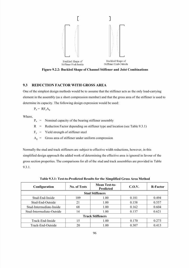
8/2/2019 Design of Bearing Stiffeners in Cold Formed C-Sections
http://slidepdf.com/reader/full/design-of-bearing-stiffeners-in-cold-formed-c-sections 110/151
96
Figure 9.2.2: Buckled Shape of Channel Stiffener and Joist Combinations
9.3 REDUCTION FACTOR WITH GROSS AREA
One of the simplest design methods would be to assume that the stiffener acts as the only load-carrying
element in the assembly (as a short compression member) and that the gross area of the stiffener is used to
determine its capacity. The following design expression would be used:
Pn = RFyAg
Where,
Pn = Nominal capacity of the bearing stiffener assembly
R = Reduction Factor depending on stiffener type and location (see Table 9.3.1)
Fy = Yield strength of stiffener steel
Ag = Gross area of stiffener under uniform compression
Normally the stud and track stiffeners are subject to effective width reductions, however, in this
simplified design approach the added work of determining the effective area is ignored in favour of the
gross section properties. The comparisons for all of the stud and track assemblies are provided in Table
9.3.1.
Table 9.3.1: Test-to-Predicted Results for the Simplified Gross Area Method
Configuration No. of Tests
Mean Test-to-
Predicted C.O.V. R-Factor
Stud Stiffeners
Stud-End-Inside 109 1.00 0.181 0.494
Stud-End-Outside 21 1.00 0.158 0.557
Stud-Intermediate-Inside 68 1.00 0.162 0.604
Stud-Intermediate-Outside 14 1.00 0.137 0.621
Track Stiffeners
Track-End-Inside 15 1.00 0.170 0.273
Track-End-Outside 20 1.00 0.307 0.413
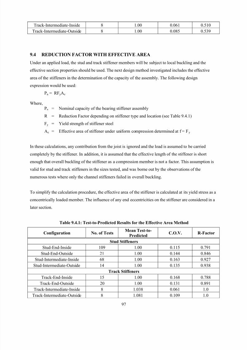
8/2/2019 Design of Bearing Stiffeners in Cold Formed C-Sections
http://slidepdf.com/reader/full/design-of-bearing-stiffeners-in-cold-formed-c-sections 111/151
97
Track-Intermediate-Inside 8 1.00 0.061 0.510
Track-Intermediate-Outside 8 1.00 0.085 0.539
9.4 REDUCTION FACTOR WITH EFFECTIVE AREA
Under an applied load, the stud and track stiffener members will be subject to local buckling and the
effective section properties should be used. The next design method investigated includes the effective
area of the stiffeners in the determination of the capacity of the assembly. The following design
expression would be used:
Pn = RFyAe
Where,
Pn = Nominal capacity of the bearing stiffener assembly
R = Reduction Factor depending on stiffener type and location (see Table 9.4.1)
Fy = Yield strength of stiffener steel
Ae = Effective area of stiffener under uniform compression determined at f = Fy
In these calculations, any contribution from the joist is ignored and the load is assumed to be carried
completely by the stiffener. In addition, it is assumed that the effective length of the stiffener is short
enough that overall buckling of the stiffener as a compression member is not a factor. This assumption is
valid for stud and track stiffeners in the sizes tested, and was borne out by the observations of the
numerous tests where only the channel stiffeners failed in overall buckling.
To simplify the calculation procedure, the effective area of the stiffener is calculated at its yield stress as a
concentrically loaded member. The influence of any end eccentricities on the stiffener are considered in a
later section.
Table 9.4.1: Test-to-Predicted Results for the Effective Area Method
Configuration No. of TestsMean Test-to-
PredictedC.O.V. R-Factor
Stud Stiffeners
Stud-End-Inside 109 1.00 0.115 0.791
Stud-End-Outside 21 1.00 0.144 0.846
Stud-Intermediate-Inside 68 1.00 0.163 0.927
Stud-Intermediate-Outside 14 1.00 0.135 0.938
Track Stiffeners
Track-End-Inside 15 1.00 0.168 0.788
Track-End-Outside 20 1.00 0.131 0.891
Track-Intermediate-Inside 8 1.038 0.061 1.0
Track-Intermediate-Outside 8 1.081 0.109 1.0
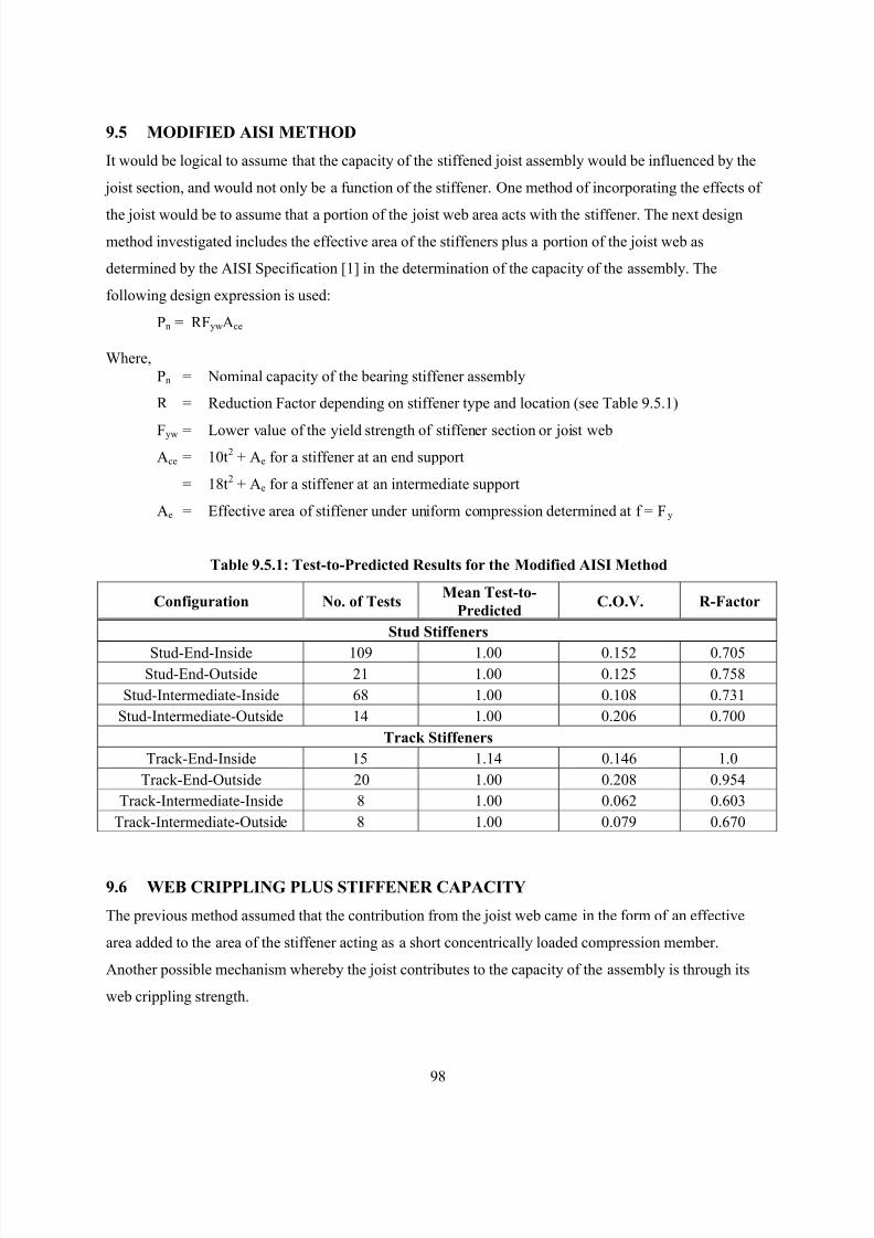
8/2/2019 Design of Bearing Stiffeners in Cold Formed C-Sections
http://slidepdf.com/reader/full/design-of-bearing-stiffeners-in-cold-formed-c-sections 112/151
98
9.5 MODIFIED AISI METHOD
It would be logical to assume that the capacity of the stiffened joist assembly would be influenced by the
joist section, and would not only be a function of the stiffener. One method of incorporating the effects of
the joist would be to assume that a portion of the joist web area acts with the stiffener. The next design
method investigated includes the effective area of the stiffeners plus a portion of the joist web as
determined by the AISI Specification [1] in the determination of the capacity of the assembly. The
following design expression is used:
Pn = RFywAce
Where,
Pn = Nominal capacity of the bearing stiffener assembly
R = Reduction Factor depending on stiffener type and location (see Table 9.5.1)
Fyw = Lower value of the yield strength of stiffener section or joist webAce = 10t2 + Ae for a stiffener at an end support
= 18t2 + Ae for a stiffener at an intermediate support
Ae = Effective area of stiffener under uniform compression determined at f = Fy
Table 9.5.1: Test-to-Predicted Results for the Modified AISI Method
Configuration No. of TestsMean Test-to-
PredictedC.O.V. R-Factor
Stud Stiffeners
Stud-End-Inside 109 1.00 0.152 0.705Stud-End-Outside 21 1.00 0.125 0.758
Stud-Intermediate-Inside 68 1.00 0.108 0.731
Stud-Intermediate-Outside 14 1.00 0.206 0.700
Track Stiffeners
Track-End-Inside 15 1.14 0.146 1.0
Track-End-Outside 20 1.00 0.208 0.954
Track-Intermediate-Inside 8 1.00 0.062 0.603
Track-Intermediate-Outside 8 1.00 0.079 0.670
9.6 WEB CRIPPLING PLUS STIFFENER CAPACITY
The previous method assumed that the contribution from the joist web came in the form of an effective
area added to the area of the stiffener acting as a short concentrically loaded compression member.
Another possible mechanism whereby the joist contributes to the capacity of the assembly is through its
web crippling strength.
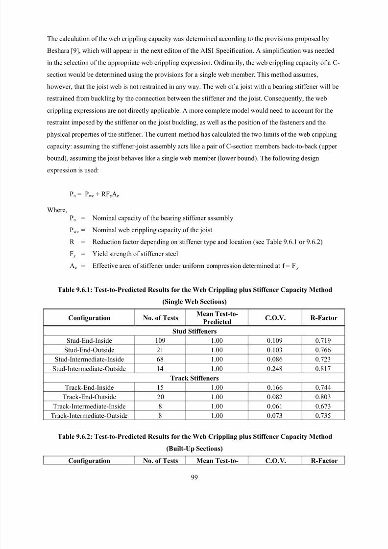
8/2/2019 Design of Bearing Stiffeners in Cold Formed C-Sections
http://slidepdf.com/reader/full/design-of-bearing-stiffeners-in-cold-formed-c-sections 113/151
99
The calculation of the web crippling capacity was determined according to the provisions proposed by
Beshara [9], which will appear in the next editon of the AISI Specification. A simplification was needed
in the selection of the appropriate web crippling expression. Ordinarily, the web crippling capacity of a C-
section would be determined using the provisions for a single web member. This method assumes,
however, that the joist web is not restrained in any way. The web of a joist with a bearing stiffener will be
restrained from buckling by the connection between the stiffener and the joist. Consequently, the web
crippling expressions are not directly applicable. A more complete model would need to account for the
restraint imposed by the stiffener on the joist buckling, as well as the position of the fasteners and the
physical properties of the stiffener. The current method has calculated the two limits of the web crippling
capacity: assuming the stiffener-joist assembly acts like a pair of C-section members back-to-back (upper
bound), assuming the joist behaves like a single web member (lower bound). The following design
expression is used:
Pn = Pwc + RFyAe
Where,
Pn = Nominal capacity of the bearing stiffener assembly
Pwc = Nominal web crippling capacity of the joist
R = Reduction factor depending on stiffener type and location (see Table 9.6.1 or 9.6.2)
Fy = Yield strength of stiffener steel
Ae = Effective area of stiffener under uniform compression determined at f = Fy
Table 9.6.1: Test-to-Predicted Results for the Web Crippling plus Stiffener Capacity Method
(Single Web Sections)
Configuration No. of TestsMean Test-to-
PredictedC.O.V. R-Factor
Stud Stiffeners
Stud-End-Inside 109 1.00 0.109 0.719
Stud-End-Outside 21 1.00 0.103 0.766
Stud-Intermediate-Inside 68 1.00 0.086 0.723
Stud-Intermediate-Outside 14 1.00 0.248 0.817
Track Stiffeners
Track-End-Inside 15 1.00 0.166 0.744
Track-End-Outside 20 1.00 0.082 0.803
Track-Intermediate-Inside 8 1.00 0.061 0.673
Track-Intermediate-Outside 8 1.00 0.073 0.735
Table 9.6.2: Test-to-Predicted Results for the Web Crippling plus Stiffener Capacity Method
(Built-Up Sections)
Configuration No. of Tests Mean Test-to- C.O.V. R-Factor
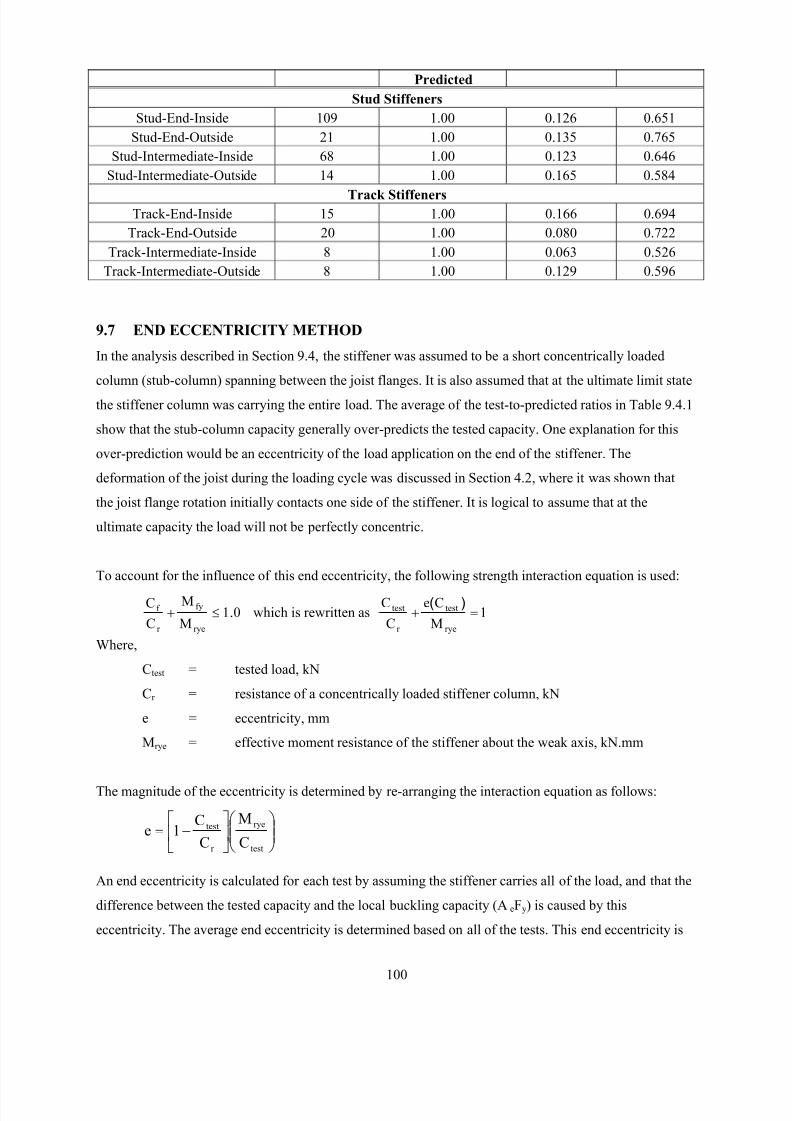
8/2/2019 Design of Bearing Stiffeners in Cold Formed C-Sections
http://slidepdf.com/reader/full/design-of-bearing-stiffeners-in-cold-formed-c-sections 114/151
100
Predicted
Stud Stiffeners
Stud-End-Inside 109 1.00 0.126 0.651
Stud-End-Outside 21 1.00 0.135 0.765
Stud-Intermediate-Inside 68 1.00 0.123 0.646
Stud-Intermediate-Outside 14 1.00 0.165 0.584
Track StiffenersTrack-End-Inside 15 1.00 0.166 0.694
Track-End-Outside 20 1.00 0.080 0.722
Track-Intermediate-Inside 8 1.00 0.063 0.526
Track-Intermediate-Outside 8 1.00 0.129 0.596
9.7 END ECCENTRICITY METHOD
In the analysis described in Section 9.4, the stiffener was assumed to be a short concentrically loaded
column (stub-column) spanning between the joist flanges. It is also assumed that at the ultimate limit state
the stiffener column was carrying the entire load. The average of the test-to-predicted ratios in Table 9.4.1
show that the stub-column capacity generally over-predicts the tested capacity. One explanation for this
over-prediction would be an eccentricity of the load application on the end of the stiffener. The
deformation of the joist during the loading cycle was discussed in Section 4.2, where it was shown that
the joist flange rotation initially contacts one side of the stiffener. It is logical to assume that at the
ultimate capacity the load will not be perfectly concentric.
To account for the influence of this end eccentricity, the following strength interaction equation is used:
01M
M
C
C
rye
fy
r
f .≤+ which is rewritten as 1M
Ce
C
C
rye
test
r
test =+)(
Where,
Ctest = tested load, kN
Cr = resistance of a concentrically loaded stiffener column, kN
e = eccentricity, mm
Mrye = effective moment resistance of the stiffener about the weak axis, kN.mm
The magnitude of the eccentricity is determined by re-arranging the interaction equation as follows:
−=
test
rye
r
test
C
M
C
C1e
An end eccentricity is calculated for each test by assuming the stiffener carries all of the load, and that the
difference between the tested capacity and the local buckling capacity (AeFy) is caused by this
eccentricity. The average end eccentricity is determined based on all of the tests. This end eccentricity is
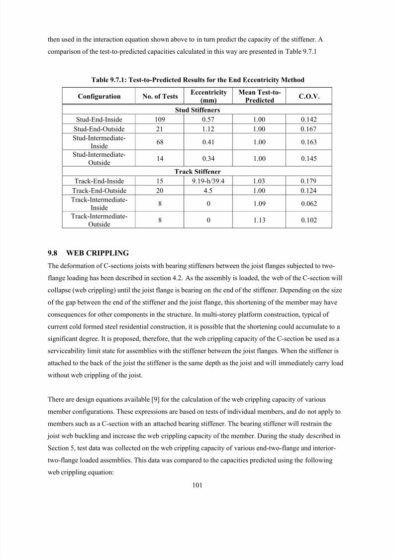
8/2/2019 Design of Bearing Stiffeners in Cold Formed C-Sections
http://slidepdf.com/reader/full/design-of-bearing-stiffeners-in-cold-formed-c-sections 115/151
101
then used in the interaction equation shown above to in turn predict the capacity of the stiffener. A
comparison of the test-to-predicted capacities calculated in this way are presented in Table 9.7.1
Table 9.7.1: Test-to-Predicted Results for the End Eccentricity Method
Configuration No. of Tests
Eccentricity
(mm)
Mean Test-to-
Predicted C.O.V.
Stud Stiffeners
Stud-End-Inside 109 0.57 1.00 0.142
Stud-End-Outside 21 1.12 1.00 0.167
Stud-Intermediate-
Inside68 0.41 1.00 0.163
Stud-Intermediate-
Outside14 0.34 1.00 0.145
Track Stiffener
Track-End-Inside 15 9.19-h/39.4 1.03 0.179
Track-End-Outside 20 4.5 1.00 0.124
Track-Intermediate-
Inside8 0 1.09 0.062
Track-Intermediate-
Outside8 0 1.13 0.102
9.8 WEB CRIPPLING
The deformation of C-sections joists with bearing stiffeners between the joist flanges subjected to two-
flange loading has been described in section 4.2. As the assembly is loaded, the web of the C-section will
collapse (web crippling) until the joist flange is bearing on the end of the stiffener. Depending on the sizeof the gap between the end of the stiffener and the joist flange, this shortening of the member may have
consequences for other components in the structure. In multi-storey platform construction, typical of
current cold formed steel residential construction, it is possible that the shortening could accumulate to a
significant degree. It is proposed, therefore, that the web crippling capacity of the C-section be used as a
serviceability limit state for assemblies with the stiffener between the joist flanges. When the stiffener is
attached to the back of the joist the stiffener is the same depth as the joist and will immediately carry load
without web crippling of the joist.
There are design equations available [9] for the calculation of the web crippling capacity of various
member configurations. These expressions are based on tests of individual members, and do not apply to
members such as a C-section with an attached bearing stiffener. The bearing stiffener will restrain the
joist web buckling and increase the web crippling capacity of the member. During the study described in
Section 5, test data was collected on the web crippling capacity of various end-two-flange and interior-
two-flange loaded assemblies. This data was compared to the capacities predicted using the following
web crippling equation:
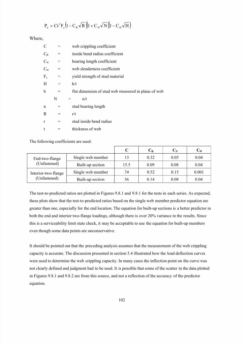
8/2/2019 Design of Bearing Stiffeners in Cold Formed C-Sections
http://slidepdf.com/reader/full/design-of-bearing-stiffeners-in-cold-formed-c-sections 116/151
102
) ) )HC1 NC1R C1FCtP H NR y
2
n −+−=
Where,
C = web crippling coefficient
CR = inside bend radius coefficient
C N = bearing length coefficient
CH = web slenderness coefficient
Fy = yield strength of stud material
H = h/t
h = flat dimension of stud web measured in plane of web
N = n/t
n = stud bearing length
R = r/t
r = stud inside bend radius
t = thickness of web
The following coefficients are used:
C CR CN CH
Single web member 13 0.32 0.05 0.04End-two-flange
(Unfastened) Built-up section 15.5 0.09 0.08 0.04
Single web member 24 0.52 0.15 0.001Interior-two-flange
(Unfastened)Built-up section 36 0.14 0.08 0.04
The test-to-predicted ratios are plotted in Figures 9.8.1 and 9.8.1 for the tests in each series. As expected,
these plots show that the test-to-predicted ratios based on the single web member predictor equation are
greater than one, especially for the end location. The equation for built-up sections is a better predictor in
both the end and interior two-flange loadings, although there is over 20% variance in the results. Since
this is a serviceability limit state check, it may be acceptable to use the equation for built-up members
even though some data points are unconservative.
It should be pointed out that the preceding analysis assumes that the measurement of the web crippling
capacity is accurate. The discussion presented in section 5.4 illustrated how the load deflection curves
were used to determine the web crippling capacity. In many cases the inflection point on the curve was
not clearly defined and judgment had to be used. It is possible that some of the scatter in the data plotted
in Figures 9.8.1 and 9.8.2 are from this source, and not a reflection of the accuracy of the predictor
equation.
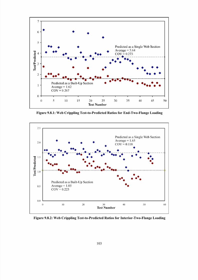
8/2/2019 Design of Bearing Stiffeners in Cold Formed C-Sections
http://slidepdf.com/reader/full/design-of-bearing-stiffeners-in-cold-formed-c-sections 117/151
103
Figure 9.8.1: Web Crippling Test-to-Predicted Ratios for End-Two-Flange Loading
Figure 9.8.2: Web Crippling Test-to-Predicted Ratios for Interior-Two-Flange Loading
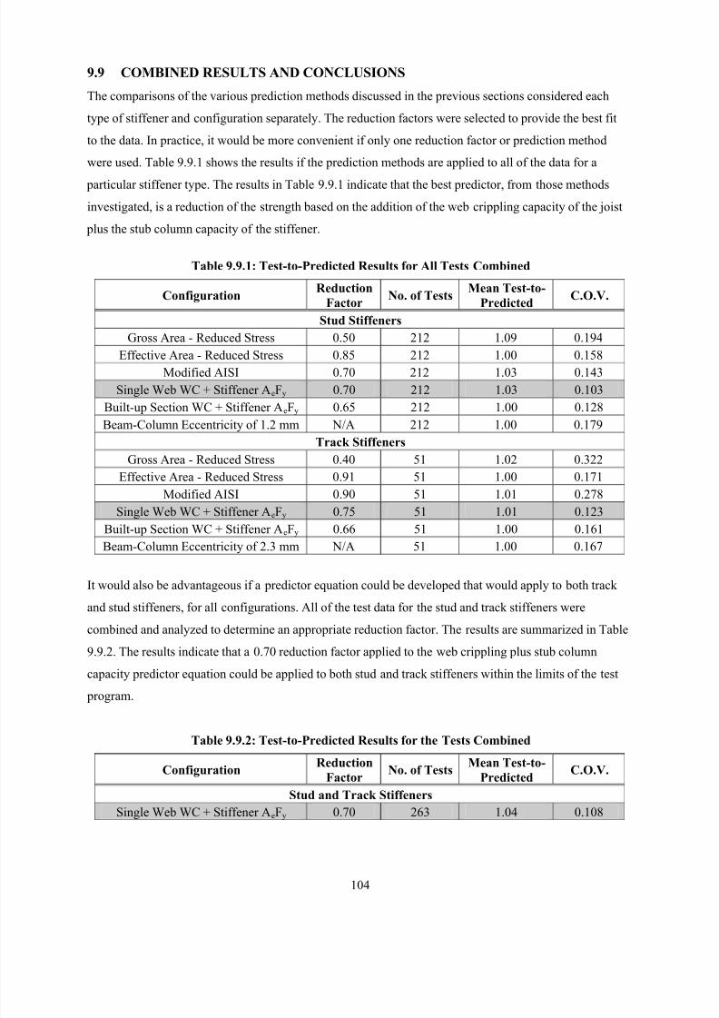
8/2/2019 Design of Bearing Stiffeners in Cold Formed C-Sections
http://slidepdf.com/reader/full/design-of-bearing-stiffeners-in-cold-formed-c-sections 118/151
104
9.9 COMBINED RESULTS AND CONCLUSIONS
The comparisons of the various prediction methods discussed in the previous sections considered each
type of stiffener and configuration separately. The reduction factors were selected to provide the best fit
to the data. In practice, it would be more convenient if only one reduction factor or prediction method
were used. Table 9.9.1 shows the results if the prediction methods are applied to all of the data for a
particular stiffener type. The results in Table 9.9.1 indicate that the best predictor, from those methods
investigated, is a reduction of the strength based on the addition of the web crippling capacity of the joist
plus the stub column capacity of the stiffener.
Table 9.9.1: Test-to-Predicted Results for All Tests Combined
ConfigurationReduction
FactorNo. of Tests
Mean Test-to-
PredictedC.O.V.
Stud Stiffeners
Gross Area - Reduced Stress 0.50 212 1.09 0.194
Effective Area - Reduced Stress 0.85 212 1.00 0.158Modified AISI 0.70 212 1.03 0.143
Single Web WC + Stiffener AeFy 0.70 212 1.03 0.103
Built-up Section WC + Stiffener AeFy 0.65 212 1.00 0.128
Beam-Column Eccentricity of 1.2 mm N/A 212 1.00 0.179
Track Stiffeners
Gross Area - Reduced Stress 0.40 51 1.02 0.322
Effective Area - Reduced Stress 0.91 51 1.00 0.171
Modified AISI 0.90 51 1.01 0.278
Single Web WC + Stiffener AeFy 0.75 51 1.01 0.123
Built-up Section WC + Stiffener AeFy 0.66 51 1.00 0.161Beam-Column Eccentricity of 2.3 mm N/A 51 1.00 0.167
It would also be advantageous if a predictor equation could be developed that would apply to both track
and stud stiffeners, for all configurations. All of the test data for the stud and track stiffeners were
combined and analyzed to determine an appropriate reduction factor. The results are summarized in Table
9.9.2. The results indicate that a 0.70 reduction factor applied to the web crippling plus stub column
capacity predictor equation could be applied to both stud and track stiffeners within the limits of the test
program.
Table 9.9.2: Test-to-Predicted Results for the Tests Combined
ConfigurationReduction
FactorNo. of Tests
Mean Test-to-
PredictedC.O.V.
Stud and Track Stiffeners
Single Web WC + Stiffener AeFy 0.70 263 1.04 0.108
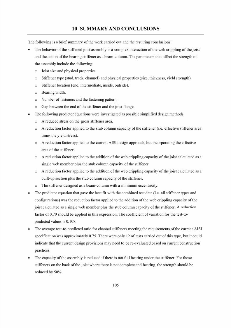
8/2/2019 Design of Bearing Stiffeners in Cold Formed C-Sections
http://slidepdf.com/reader/full/design-of-bearing-stiffeners-in-cold-formed-c-sections 119/151
105
10 SUMMARY AND CONCLUSIONS
The following is a brief summary of the work carried out and the resulting conclusions:
• The behavior of the stiffened joist assembly is a complex interaction of the web crippling of the joist
and the action of the bearing stiffener as a beam-column. The parameters that affect the strength of
the assembly include the following:
o Joist size and physical properties.
o Stiffener type (stud, track, channel) and physical properties (size, thickness, yield strength).
o Stiffener location (end, intermediate, inside, outside).
o Bearing width.
o Number of fasteners and the fastening pattern.
o Gap between the end of the stiffener and the joist flange.
• The following predictor equations were investigated as possible simplified design methods:
o A reduced stress on the gross stiffener area.
o A reduction factor applied to the stub column capacity of the stiffener (i.e. effective stiffener area
times the yield stress).
o A reduction factor applied to the current AISI design approach, but incorporating the effective
area of the stiffener.
o A reduction factor applied to the addition of the web crippling capacity of the joist calculated as a
single web member plus the stub column capacity of the stiffener.
o A reduction factor applied to the addition of the web crippling capacity of the joist calculated as a built-up section plus the stub column capacity of the stiffener.
o The stiffener designed as a beam-column with a minimum eccentricity.
• The predictor equation that gave the best fit with the combined test data (i.e. all stiffener types and
configurations) was the reduction factor applied to the addition of the web crippling capacity of the
joist calculated as a single web member plus the stub column capacity of the stiffener. A reduction
factor of 0.70 should be applied in this expression. The coefficient of variation for the test-to-
predicted values is 0.108.
• The average test-to-predicted ratio for channel stiffeners meeting the requirements of the current AISIspecification was approximately 0.75. There were only 12 of tests carried out of this type, but it could
indicate that the current design provisions may need to be re-evaluated based on current construction
practices.
• The capacity of the assembly is reduced if there is not full bearing under the stiffener. For those
stiffeners on the back of the joist where there is not complete end bearing, the strength should be
reduced by 50%.
8/2/2019 Design of Bearing Stiffeners in Cold Formed C-Sections
http://slidepdf.com/reader/full/design-of-bearing-stiffeners-in-cold-formed-c-sections 120/151
106
• Fastening the joist flanges to the support does not have a significant effect on the strength of the
assembly.
• The gap between the stiffener and the joist flange (inside locations) does not have a significant effect
on the ultimate strength of the assembly, however, this gap could lead to serviceability problems. It is
recommended that the length of the stiffener should be not less than the depth of the joist minus 10
mm (3/8 in.). This will provide sufficient clearance for installation and limit the deformations.
• The fasteners should be spaced at least a distance of h/6 (where h = depth of the joist) away from the
joist flanges.
• The web crippling capacity of the joist should be considered as the serviceability limit state for the
assembly. From the data collected, the web crippling capacity of the stiffened joist can be predicted
using the new AISI design expression for built-up members. This expression will over-estimate the
capacity, however, this conservatism may be justified given the scatter in the test data.
• A finite element model of the joist has been developed and calibrated to test results. This model can
predict the web crippling capacity of the joist as well as the forces developed in the fasteners
connecting the joist to the stiffener. This model will be used in future work to run parametric studies
on the influence of varying factors such as fastener location and material properties, and eventually to
develop a design expression to calculate the web crippling capacity of joists with bearing stiffeners.
• If a more comprehensive model of the stiffener were to be developed, it would need to recognize that
the stiffener behaves as a beam-column acted upon forces in the fasteners connecting the stiffener to
the joist as well as an eccentric axial load. The finite element model could be used to provide data to
support the development of a design method.
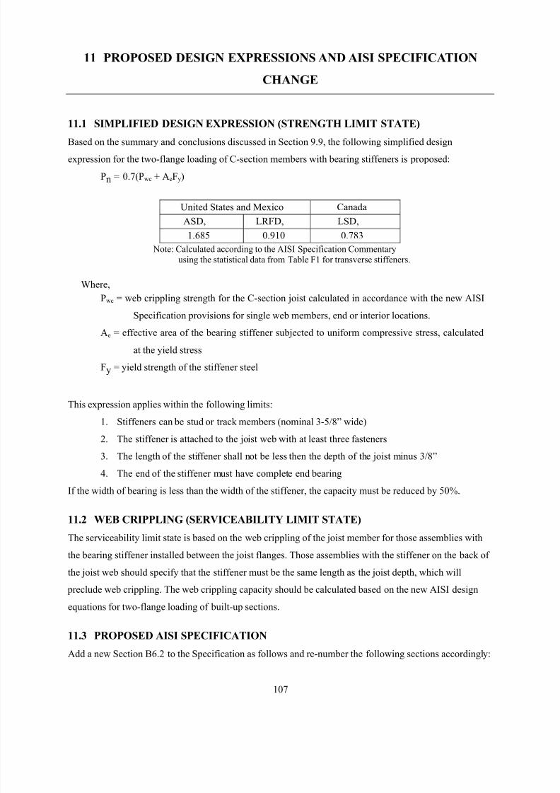
8/2/2019 Design of Bearing Stiffeners in Cold Formed C-Sections
http://slidepdf.com/reader/full/design-of-bearing-stiffeners-in-cold-formed-c-sections 121/151
107
11 PROPOSED DESIGN EXPRESSIONS AND AISI SPECIFICATION
CHANGE
11.1 SIMPLIFIED DESIGN EXPRESSION (STRENGTH LIMIT STATE)
Based on the summary and conclusions discussed in Section 9.9, the following simplified design
expression for the two-flange loading of C-section members with bearing stiffeners is proposed:
Pn = 0.7(Pwc + AeFy)
United States and Mexico Canada
ASD, LRFD, LSD,
1.685 0.910 0.783
Note: Calculated according to the AISI Specification Commentary
using the statistical data from Table F1 for transverse stiffeners.
Where,
Pwc = web crippling strength for the C-section joist calculated in accordance with the new AISI
Specification provisions for single web members, end or interior locations.
Ae = effective area of the bearing stiffener subjected to uniform compressive stress, calculated
at the yield stress
Fy = yield strength of the stiffener steel
This expression applies within the following limits:
1. Stiffeners can be stud or track members (nominal 3-5/8” wide)
2. The stiffener is attached to the joist web with at least three fasteners
3. The length of the stiffener shall not be less then the depth of the joist minus 3/8”
4. The end of the stiffener must have complete end bearing
If the width of bearing is less than the width of the stiffener, the capacity must be reduced by 50%.
11.2 WEB CRIPPLING (SERVICEABILITY LIMIT STATE)
The serviceability limit state is based on the web crippling of the joist member for those assemblies with
the bearing stiffener installed between the joist flanges. Those assemblies with the stiffener on the back of
the joist web should specify that the stiffener must be the same length as the joist depth, which will
preclude web crippling. The web crippling capacity should be calculated based on the new AISI design
equations for two-flange loading of built-up sections.
11.3 PROPOSED AISI SPECIFICATION
Add a new Section B6.2 to the Specification as follows and re-number the following sections accordingly:
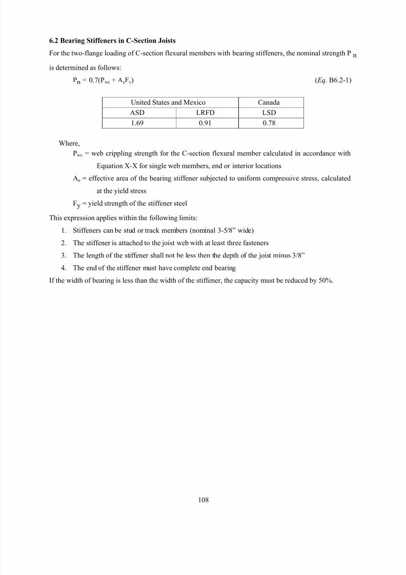
8/2/2019 Design of Bearing Stiffeners in Cold Formed C-Sections
http://slidepdf.com/reader/full/design-of-bearing-stiffeners-in-cold-formed-c-sections 122/151
108
6.2 Bearing Stiffeners in C-Section Joists
For the two-flange loading of C-section flexural members with bearing stiffeners, the nominal strength Pn
is determined as follows:
Pn = 0.7(Pwc + AeFy) ( Eq. B6.2-1)
United States and Mexico Canada
ASD LRFD LSD
1.69 0.91 0.78
Where,
Pwc = web crippling strength for the C-section flexural member calculated in accordance with
Equation X-X for single web members, end or interior locations
Ae = effective area of the bearing stiffener subjected to uniform compressive stress, calculated
at the yield stress
Fy = yield strength of the stiffener steel
This expression applies within the following limits:
1. Stiffeners can be stud or track members (nominal 3-5/8” wide)
2. The stiffener is attached to the joist web with at least three fasteners
3. The length of the stiffener shall not be less then the depth of the joist minus 3/8”
4. The end of the stiffener must have complete end bearing
If the width of bearing is less than the width of the stiffener, the capacity must be reduced by 50%.
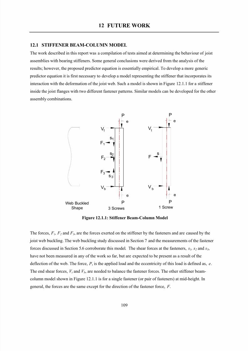
8/2/2019 Design of Bearing Stiffeners in Cold Formed C-Sections
http://slidepdf.com/reader/full/design-of-bearing-stiffeners-in-cold-formed-c-sections 123/151
109
12 FUTURE WORK
12.1 STIFFENER BEAM-COLUMN MODEL
The work described in this report was a compilation of tests aimed at determining the behaviour of joist
assemblies with bearing stiffeners. Some general conclusions were derived from the analysis of the
results; however, the proposed predictor equation is essentially empirical. To develop a more generic
predictor equation it is first necessary to develop a model representing the stiffener that incorporates its
interaction with the deformation of the joist web. Such a model is shown in Figure 12.1.1 for a stiffener
inside the joist flanges with two different fastener patterns. Similar models can be developed for the other
assembly combinations.
Figure 12.1.1: Stiffener Beam-Column Model
The forces, F 1 , F 2 and F 3, are the forces exerted on the stiffener by the fasteners and are caused by the
joist web buckling. The web buckling study discussed in Section 7 and the measurements of the fastener
forces discussed in Section 5.6 corroborate this model. The shear forces at the fasteners, s1 , s2 and s3,
have not been measured in any of the work so far, but are expected to be present as a result of the
deflection of the web. The force, P , is the applied load and the eccentricity of this load is defined as, e.
The end shear forces, V t and V b, are needed to balance the fastener forces. The other stiffener beam-
column model shown in Figure 12.1.1 is for a single fastener (or pair of fasteners) at mid-height. In
general, the forces are the same except for the direction of the fastener force, F .
e
P
Vt
1F1s
2F
3Fs3
bV
P
e
V
F
V
P
e
e
P
Web Buckled
Shape 3 Screws 1 Screw
t
s2
b
s
8/2/2019 Design of Bearing Stiffeners in Cold Formed C-Sections
http://slidepdf.com/reader/full/design-of-bearing-stiffeners-in-cold-formed-c-sections 124/151
110
The design of this stiffener could be carried out according to the current provisions of the AISI
Specification for beam-columns if the eccentricity of the applied load and the fastener forces were known.
This information could be obtained through the following process:
Step 1: Use the finite element model described in Section 8 to run a parametric study on the influence of
fastener location and fastener stiffness on the fastener forces.
Step 2: Statistically analyze the results of the FE parametric study to develop a multiple regression
equation that can be used to predict the fastener forces in a stiffener assembly.
Step 3: Use the regression equation from Step 2 to determine the forces in the fasteners for each of the
assemblies tested. Once the fastener forces are known the equivalent eccentricity of the load can be
calculated based on the beam-column interaction equation. A relationship can be developed relating
relevant parameters of the assembly to the resulting eccentricity.
Step 4: The predictor equation for the fastener forces along with the predictor equation for the end
eccentricity can be incorporated into a beam-column design expression that could be included in the AISI
Specification as an alternative to the simplified design expressions.
The overall column buckling capacity of the stiffener will also be a consideration. The discussions so far
have focused on stiffeners that fail through local buckling, but there are other stiffeners (i.e. channel
members) that will fail by overall column buckling. A stability check on the stiffener will need to be
included for these smaller stiffeners. One task will be to find the limiting slenderness where overall
buckling takes over from local buckling.
12.2 STIFFENED PLATE MODEL
The tests of the channel stiffeners have shown that one of the failure modes is overall buckling of the
stiffener and joist web. This type of failure mechanism is quite different from the local buckling type of
failure observed for the stud and track stiffeners. The buckling mode of failure lends itself to an
alternative model of the assembly, specifically a stiffened plate model.
The bucking of plates subject to edge loading has been investigated by many researchers over the years.
The exact solution for the critical elastic buckling stress is possible for very simple plates and loadingconfiguration, but for more complicated assemblies, approximate solutions must be used or the assembly
must be tested. There have been a large number of research projects carried out investigating the web
crippling capacity of cold formed steel structural members. There have also been many studies of the
behavior of stiffened plates, originating with the ship building industry and then expanded upon
considerably by the aircraft designers.
8/2/2019 Design of Bearing Stiffeners in Cold Formed C-Sections
http://slidepdf.com/reader/full/design-of-bearing-stiffeners-in-cold-formed-c-sections 125/151
111
The development of the stiffened plate model for the stiffened C-section could consider the interactive
buckling of a stiffener connected to a plate by discrete fasteners. The reason for pursuing this type of
study would be to determine the limit when an assembly stops behaving like a stiffener plate subjected to
patch loading, and starts to behave like a stiffener subjected to eccentric loads and fastener forces.
12.3 SERVICABILITY LIMIT STATEThe discussion in Section 9.8 indicated that web crippling of the joist could be considered as a
serviceability limit state. A design expression to calculate this capacity could be determine using the
following methodology:
Step 1: The finite element model described in Section 8 can be used to run a parametric study on the
influence of fastener location and stiffness on the web crippling capacity of the joist.
Step 2: The results of the FE parametric study can be statistically analyzed to develop a multiple
regression equation that can be used to predict the web crippling capacity of the joist in a stiffenedassembly. This predictor equation would be of the same form as the AISI Specification (see section 9.8)
and would incorporate parameters such as the fastener pattern and location, joist properties, stiffener
properties.
12.4 OTHER ASSEMBLIES AND STIFFENER TYPES
The following are suggestions for future research topics:
• A cold formed steel C-section with a bearing stiffener is normally part of an assembly that can
include a rim track and a plywood sub-floor. Additional testing needs to be carried out on these
assemblies to determine what additional capacity is developed.
• The use of other types of bearing stiffeners such as clip angles should be investigated.
• All of the tests carried out as part of this research have been two-flange loading. This was selected
since it is the most severe loading condition that a stiffener will experience. In practice there are
situations where the member is subjected to one flange loading, or a combination of one and two
flange loading. These conditions also need to be investigated.
• Additional data would be useful for the track stiffeners.
8/2/2019 Design of Bearing Stiffeners in Cold Formed C-Sections
http://slidepdf.com/reader/full/design-of-bearing-stiffeners-in-cold-formed-c-sections 126/151
112
13 ACKNOWLEDGMENTS
This project is funded by the American Iron and Steel Institute and the Canadian Sheet Steel Building
Institute. Project direction is provided by Sub-committee 10 of the AISI Committee on Specifications,
and by the CSSBI Research & Development Committee. The support of these two organizations is greatly
appreciated. The University of Waterloo, Department of Civil Engineering and the Canadian Cold
Formed Steel Research Group are also recognized for their support of this research activity.
8/2/2019 Design of Bearing Stiffeners in Cold Formed C-Sections
http://slidepdf.com/reader/full/design-of-bearing-stiffeners-in-cold-formed-c-sections 127/151
113
14 REFERENCES
1. American Iron and Steel Institute, Specification for the Design of Cold-Formed Steel Structural
Members with the 1999 Supplement, Washington, D.C. , June, 1997
2. Canadian Standards Association, CSA-S136-94 Cold Formed Steel Structural Members, Rexdale(Toronto), Ontario, Canada 1994
3. LaBoube, R.A., and Yu, W.W., Structural Behavior of Beam Webs Subjected toBending Stress,
final report, civil engineering study 78-1, University of Missouri-Rolla, June 1978
4. LaBoube, R.A., and Yu, W.W., Structural Behavior of Beam Webs Subjected Primarily to Shear ,
final report, civil engineering study 78-2, University of Missouri-Rolla, June 1978
5. LaBoube, R.A., and Yu, W.W., Structural Behavior of Beam Webs Subjected to a Combination of
Bending and Shear , final report, civil engineering study 78-3, University of Missouri-Rolla, June
1978.
6. Hetrakul, N., and Yu, W.W., Structural Behavior of Beam Webs Subjected to Web Crippling and
a Combination of Web Crippling and Bending, final report, civil engineering study 78-4,
University of Missouri-Rolla, June 1978
7. Nguyen, P., and Yu, W.W., Structural Behavior of Transversely Reinforced Beam Webs, final
report, Civil Engineering Study 78-5, University of Missouri-Rolla, USA, June 1978
8. Nguyen, P., and Yu, W.W., Structural Behavior of Longitudinally Reinforced Beam Webs, final
report, Civil Engineering Study 78-6, University of Missouri-Rolla, USA, June 1978
9. Beshara, B., Web Crippling of Cold Formed Steel Members, M.A.Sc. Thesis, University of
Waterloo, Canada, 1999
10. American Iron and Steel Institute, Specification for the Design of Cold-Formed Steel Structural
Members, Washington, D.C., June, 1997, Including Supplement No.1, July 30, 1999
11. Canadian Standards Association, CSA-S136-94 Cold Formed Steel Structural Members, Rexdale
(Toronto), 1994
12. Nguyen, P., and Yu, W.W., Structural Behavior of Transversely Reinforced Beam Webs, final
report, Civil Engineering Study 78-5, University of Missouri-Rolla, USA, June 1978
13. Fox, S.R and Schuster, R.M., “Tests of Cold Formed Steel Floor Joists With Bearing Stiffeners”,
Proceedings of the 14th International Specialty Conference on Cold Formed Steel Structures,
University of Missouri-Rolla, October 1998
14. Fox, S.R. and Schuster, R.M. “First Summary Report: Bearing Stiffeners in Cold Formed Steel
C-Sections”, American Iron and Steel Institute, Washington, D.C., February, 2000
15. Fox, S.R and Schuster, R.M., “Strength of Bearing Stiffeners in Cold Formed Steel C-Sections”,
Proceedings of the 15th International Specialty Conference on Cold Formed Steel Structures,University of Missouri-Rolla, October 2000
8/2/2019 Design of Bearing Stiffeners in Cold Formed C-Sections
http://slidepdf.com/reader/full/design-of-bearing-stiffeners-in-cold-formed-c-sections 128/151
114
16. Fox, S.R., “Effect of End Gap and Screw Pattern on the Bearing Capacity of Stiffened Cold
Formed Steel C-sections”, Canadian Cold Formed Steel Research Group report, University of
Waterloo, Waterloo, Ontario, Canada, October 1999
17. Fox, S.R., “Effect of Bearing Width on the Bearing Capacity of Stiffened Cold Formed Steel C-
sections”, Canadian Cold Formed Steel Research Group report, University of Waterloo,
Waterloo, Ontario, Canada, October 1999
18. Fox, S.R., “Effects of Material Thickness and Fastening the Joist Flanges on the Capacity of
Bearing Stiffeners in Cold Formed Steel C-sections”, Canadian Cold Formed Steel Research
Group report, University of Waterloo, Waterloo, Ontario, Canada, May 2000
19. Fox, S.R., “Measurement of the Fastener Forces and Web Crippling Capacity of Bearing
Stiffeners in Cold Formed Steel C-Sections”, Canadian Cold Formed Steel Research Group
report, University of Waterloo, Waterloo, Ontario, Canada, February 2001
20. American Iron and Steel Institute, AISI/COFS/GP 2001, Standard for Cold-Formed Steel
Framing – General Provisions, Washington, D.C., 2001
21. Canadian Sheet Steel Building Institute, Residential Steel Framing – Installation Manual , CSSBI
55-99, Cambridge, Ontario, August 1999.
22. Frisch-Fay, R., Flexible Bars, Butterworths Scientific Publications, London, 1962

8/2/2019 Design of Bearing Stiffeners in Cold Formed C-Sections
http://slidepdf.com/reader/full/design-of-bearing-stiffeners-in-cold-formed-c-sections 129/151
115
APPENDIX A:
TEST SPECIMEN MATERIAL PROPERTIES AND STIFFENER
DIMENSIONS
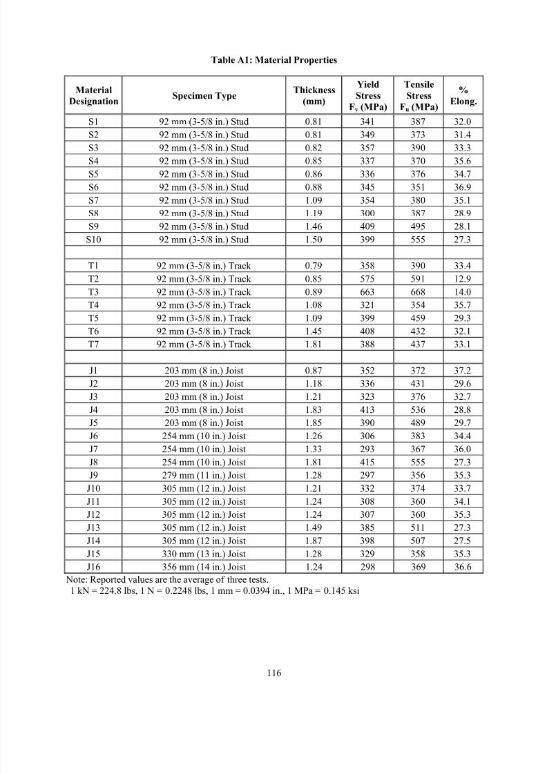
8/2/2019 Design of Bearing Stiffeners in Cold Formed C-Sections
http://slidepdf.com/reader/full/design-of-bearing-stiffeners-in-cold-formed-c-sections 130/151
116
Table A1: Material Properties
Material
DesignationSpecimen Type
Thickness
(mm)
Yield
Stress
Fy (MPa)
Tensile
Stress
Fu (MPa)
%
Elong.
S1 92 mm (3-5/8 in.) Stud 0.81 341 387 32.0
S2 92 mm (3-5/8 in.) Stud 0.81 349 373 31.4S3 92 mm (3-5/8 in.) Stud 0.82 357 390 33.3
S4 92 mm (3-5/8 in.) Stud 0.85 337 370 35.6
S5 92 mm (3-5/8 in.) Stud 0.86 336 376 34.7
S6 92 mm (3-5/8 in.) Stud 0.88 345 351 36.9
S7 92 mm (3-5/8 in.) Stud 1.09 354 380 35.1
S8 92 mm (3-5/8 in.) Stud 1.19 300 387 28.9
S9 92 mm (3-5/8 in.) Stud 1.46 409 495 28.1
S10 92 mm (3-5/8 in.) Stud 1.50 399 555 27.3
T1 92 mm (3-5/8 in.) Track 0.79 358 390 33.4
T2 92 mm (3-5/8 in.) Track 0.85 575 591 12.9
T3 92 mm (3-5/8 in.) Track 0.89 663 668 14.0
T4 92 mm (3-5/8 in.) Track 1.08 321 354 35.7
T5 92 mm (3-5/8 in.) Track 1.09 399 459 29.3
T6 92 mm (3-5/8 in.) Track 1.45 408 432 32.1
T7 92 mm (3-5/8 in.) Track 1.81 388 437 33.1
J1 203 mm (8 in.) Joist 0.87 352 372 37.2
J2 203 mm (8 in.) Joist 1.18 336 431 29.6
J3 203 mm (8 in.) Joist 1.21 323 376 32.7
J4 203 mm (8 in.) Joist 1.83 413 536 28.8
J5 203 mm (8 in.) Joist 1.85 390 489 29.7
J6 254 mm (10 in.) Joist 1.26 306 383 34.4
J7 254 mm (10 in.) Joist 1.33 293 367 36.0
J8 254 mm (10 in.) Joist 1.81 415 555 27.3
J9 279 mm (11 in.) Joist 1.28 297 356 35.3
J10 305 mm (12 in.) Joist 1.21 332 374 33.7
J11 305 mm (12 in.) Joist 1.24 308 360 34.1
J12 305 mm (12 in.) Joist 1.24 307 360 35.3
J13 305 mm (12 in.) Joist 1.49 385 511 27.3
J14 305 mm (12 in.) Joist 1.87 398 507 27.5J15 330 mm (13 in.) Joist 1.28 329 358 35.3
J16 356 mm (14 in.) Joist 1.24 298 369 36.6
Note: Reported values are the average of three tests.
1 kN = 224.8 lbs, 1 N = 0.2248 lbs, 1 mm = 0.0394 in., 1 MPa = 0.145 ksi
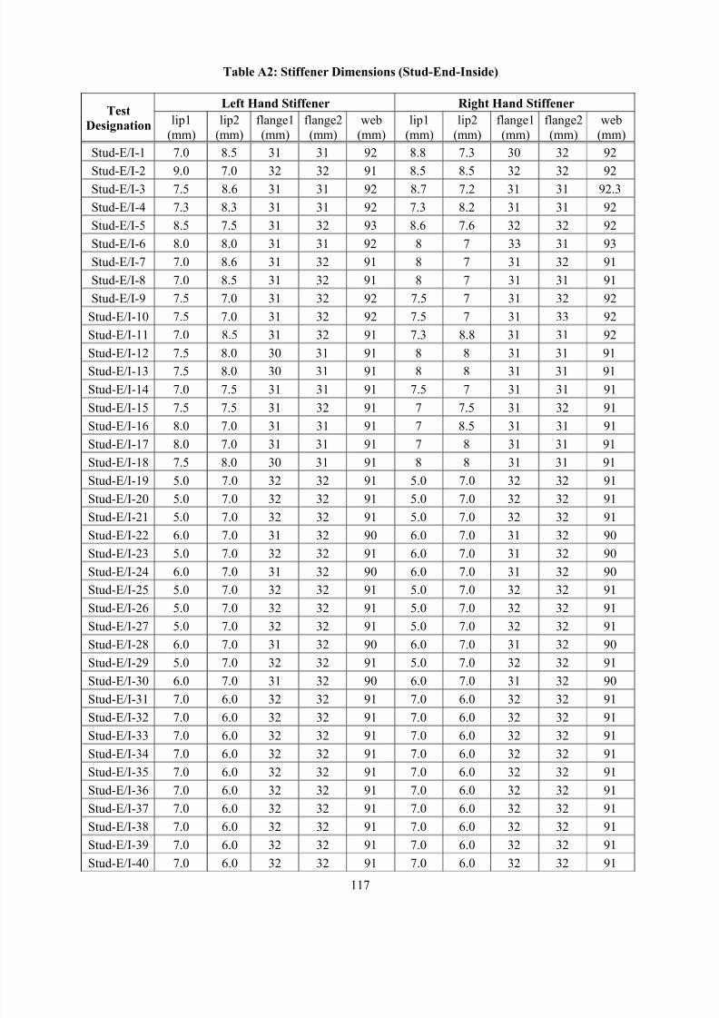
8/2/2019 Design of Bearing Stiffeners in Cold Formed C-Sections
http://slidepdf.com/reader/full/design-of-bearing-stiffeners-in-cold-formed-c-sections 131/151
117
Table A2: Stiffener Dimensions (Stud-End-Inside)
Left Hand Stiffener Right Hand StiffenerTest
Designation lip1
(mm)
lip2
(mm)
flange1
(mm)
flange2
(mm)
web
(mm)
lip1
(mm)
lip2
(mm)
flange1
(mm)
flange2
(mm)
web
(mm)
Stud-E/I-1 7.0 8.5 31 31 92 8.8 7.3 30 32 92
Stud-E/I-2 9.0 7.0 32 32 91 8.5 8.5 32 32 92
Stud-E/I-3 7.5 8.6 31 31 92 8.7 7.2 31 31 92.3
Stud-E/I-4 7.3 8.3 31 31 92 7.3 8.2 31 31 92
Stud-E/I-5 8.5 7.5 31 32 93 8.6 7.6 32 32 92
Stud-E/I-6 8.0 8.0 31 31 92 8 7 33 31 93
Stud-E/I-7 7.0 8.6 31 32 91 8 7 31 32 91
Stud-E/I-8 7.0 8.5 31 32 91 8 7 31 31 91
Stud-E/I-9 7.5 7.0 31 32 92 7.5 7 31 32 92
Stud-E/I-10 7.5 7.0 31 32 92 7.5 7 31 33 92
Stud-E/I-11 7.0 8.5 31 32 91 7.3 8.8 31 31 92
Stud-E/I-12 7.5 8.0 30 31 91 8 8 31 31 91Stud-E/I-13 7.5 8.0 30 31 91 8 8 31 31 91
Stud-E/I-14 7.0 7.5 31 31 91 7.5 7 31 31 91
Stud-E/I-15 7.5 7.5 31 32 91 7 7.5 31 32 91
Stud-E/I-16 8.0 7.0 31 31 91 7 8.5 31 31 91
Stud-E/I-17 8.0 7.0 31 31 91 7 8 31 31 91
Stud-E/I-18 7.5 8.0 30 31 91 8 8 31 31 91
Stud-E/I-19 5.0 7.0 32 32 91 5.0 7.0 32 32 91
Stud-E/I-20 5.0 7.0 32 32 91 5.0 7.0 32 32 91
Stud-E/I-21 5.0 7.0 32 32 91 5.0 7.0 32 32 91
Stud-E/I-22 6.0 7.0 31 32 90 6.0 7.0 31 32 90Stud-E/I-23 5.0 7.0 32 32 91 6.0 7.0 31 32 90
Stud-E/I-24 6.0 7.0 31 32 90 6.0 7.0 31 32 90
Stud-E/I-25 5.0 7.0 32 32 91 5.0 7.0 32 32 91
Stud-E/I-26 5.0 7.0 32 32 91 5.0 7.0 32 32 91
Stud-E/I-27 5.0 7.0 32 32 91 5.0 7.0 32 32 91
Stud-E/I-28 6.0 7.0 31 32 90 6.0 7.0 31 32 90
Stud-E/I-29 5.0 7.0 32 32 91 5.0 7.0 32 32 91
Stud-E/I-30 6.0 7.0 31 32 90 6.0 7.0 31 32 90
Stud-E/I-31 7.0 6.0 32 32 91 7.0 6.0 32 32 91
Stud-E/I-32 7.0 6.0 32 32 91 7.0 6.0 32 32 91
Stud-E/I-33 7.0 6.0 32 32 91 7.0 6.0 32 32 91
Stud-E/I-34 7.0 6.0 32 32 91 7.0 6.0 32 32 91
Stud-E/I-35 7.0 6.0 32 32 91 7.0 6.0 32 32 91
Stud-E/I-36 7.0 6.0 32 32 91 7.0 6.0 32 32 91
Stud-E/I-37 7.0 6.0 32 32 91 7.0 6.0 32 32 91
Stud-E/I-38 7.0 6.0 32 32 91 7.0 6.0 32 32 91
Stud-E/I-39 7.0 6.0 32 32 91 7.0 6.0 32 32 91
Stud-E/I-40 7.0 6.0 32 32 91 7.0 6.0 32 32 91
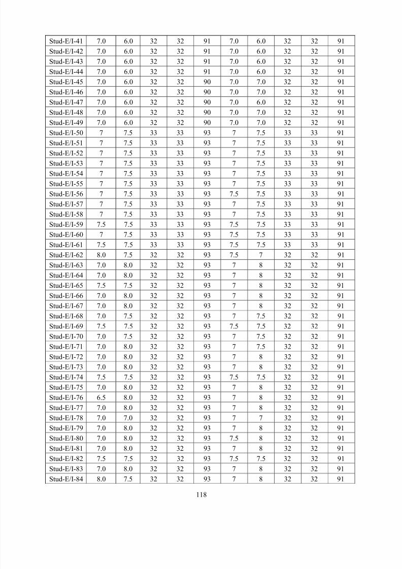
8/2/2019 Design of Bearing Stiffeners in Cold Formed C-Sections
http://slidepdf.com/reader/full/design-of-bearing-stiffeners-in-cold-formed-c-sections 132/151
118
Stud-E/I-41 7.0 6.0 32 32 91 7.0 6.0 32 32 91
Stud-E/I-42 7.0 6.0 32 32 91 7.0 6.0 32 32 91
Stud-E/I-43 7.0 6.0 32 32 91 7.0 6.0 32 32 91
Stud-E/I-44 7.0 6.0 32 32 91 7.0 6.0 32 32 91
Stud-E/I-45 7.0 6.0 32 32 90 7.0 7.0 32 32 91
Stud-E/I-46 7.0 6.0 32 32 90 7.0 7.0 32 32 91
Stud-E/I-47 7.0 6.0 32 32 90 7.0 6.0 32 32 91
Stud-E/I-48 7.0 6.0 32 32 90 7.0 7.0 32 32 91
Stud-E/I-49 7.0 6.0 32 32 90 7.0 7.0 32 32 91
Stud-E/I-50 7 7.5 33 33 93 7 7.5 33 33 91
Stud-E/I-51 7 7.5 33 33 93 7 7.5 33 33 91
Stud-E/I-52 7 7.5 33 33 93 7 7.5 33 33 91
Stud-E/I-53 7 7.5 33 33 93 7 7.5 33 33 91
Stud-E/I-54 7 7.5 33 33 93 7 7.5 33 33 91
Stud-E/I-55 7 7.5 33 33 93 7 7.5 33 33 91
Stud-E/I-56 7 7.5 33 33 93 7.5 7.5 33 33 91
Stud-E/I-57 7 7.5 33 33 93 7 7.5 33 33 91
Stud-E/I-58 7 7.5 33 33 93 7 7.5 33 33 91
Stud-E/I-59 7.5 7.5 33 33 93 7.5 7.5 33 33 91
Stud-E/I-60 7 7.5 33 33 93 7.5 7.5 33 33 91
Stud-E/I-61 7.5 7.5 33 33 93 7.5 7.5 33 33 91
Stud-E/I-62 8.0 7.5 32 32 93 7.5 7 32 32 91
Stud-E/I-63 7.0 8.0 32 32 93 7 8 32 32 91
Stud-E/I-64 7.0 8.0 32 32 93 7 8 32 32 91
Stud-E/I-65 7.5 7.5 32 32 93 7 8 32 32 91
Stud-E/I-66 7.0 8.0 32 32 93 7 8 32 32 91Stud-E/I-67 7.0 8.0 32 32 93 7 8 32 32 91
Stud-E/I-68 7.0 7.5 32 32 93 7 7.5 32 32 91
Stud-E/I-69 7.5 7.5 32 32 93 7.5 7.5 32 32 91
Stud-E/I-70 7.0 7.5 32 32 93 7 7.5 32 32 91
Stud-E/I-71 7.0 8.0 32 32 93 7 7.5 32 32 91
Stud-E/I-72 7.0 8.0 32 32 93 7 8 32 32 91
Stud-E/I-73 7.0 8.0 32 32 93 7 8 32 32 91
Stud-E/I-74 7.5 7.5 32 32 93 7.5 7.5 32 32 91
Stud-E/I-75 7.0 8.0 32 32 93 7 8 32 32 91
Stud-E/I-76 6.5 8.0 32 32 93 7 8 32 32 91Stud-E/I-77 7.0 8.0 32 32 93 7 8 32 32 91
Stud-E/I-78 7.0 7.0 32 32 93 7 7 32 32 91
Stud-E/I-79 7.0 8.0 32 32 93 7 8 32 32 91
Stud-E/I-80 7.0 8.0 32 32 93 7.5 8 32 32 91
Stud-E/I-81 7.0 8.0 32 32 93 7 8 32 32 91
Stud-E/I-82 7.5 7.5 32 32 93 7.5 7.5 32 32 91
Stud-E/I-83 7.0 8.0 32 32 93 7 8 32 32 91
Stud-E/I-84 8.0 7.5 32 32 93 7 8 32 32 91
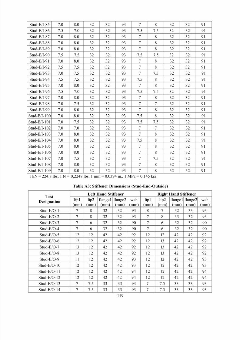
8/2/2019 Design of Bearing Stiffeners in Cold Formed C-Sections
http://slidepdf.com/reader/full/design-of-bearing-stiffeners-in-cold-formed-c-sections 133/151
119
Stud-E/I-85 7.0 8.0 32 32 93 7 8 32 32 91
Stud-E/I-86 7.5 7.0 32 32 93 7.5 7.5 32 32 91
Stud-E/I-87 7.0 8.0 32 32 93 7 8 32 32 91
Stud-E/I-88 7.0 8.0 32 32 93 7 8 32 32 91
Stud-E/I-89 7.0 8.0 32 32 93 7 8 32 32 91
Stud-E/I-90 7.5 7.5 32 32 93 7.5 7.5 32 32 91
Stud-E/I-91 7.0 8.0 32 32 93 7 8 32 32 91
Stud-E/I-92 7.5 7.5 32 32 93 7 8 32 32 91
Stud-E/I-93 7.0 7.5 32 32 93 7 7.5 32 32 91
Stud-E/I-94 7.5 7.5 32 32 93 7.5 8 32 32 91
Stud-E/I-95 7.0 8.0 32 32 93 7 8 32 32 91
Stud-E/I-96 7.5 7.0 32 32 93 7.5 7.5 32 32 91
Stud-E/I-97 7.0 8.0 32 32 93 7 8 32 32 91
Stud-E/I-98 7.0 7.5 32 32 93 7 7 32 32 91
Stud-E/I-99 7.0 8.0 32 32 93 7 8 32 32 91
Stud-E/I-100 7.0 8.0 32 32 93 7.5 8 32 32 91
Stud-E/I-101 7.0 7.5 32 32 93 7.5 7.5 32 32 91
Stud-E/I-102 7.0 7.0 32 32 93 7 7 32 32 91
Stud-E/I-103 7.0 8.0 32 32 93 7 8 32 32 91
Stud-E/I-104 7.0 8.0 32 32 93 7.5 8 32 32 91
Stud-E/I-105 7.0 8.0 32 32 93 7 8 32 32 91
Stud-E/I-106 7.0 8.0 32 32 93 7 8 32 32 91
Stud-E/I-107 7.0 7.5 32 32 93 7 7.5 32 32 91
Stud-E/I-108 7.0 8.0 32 32 93 7 8 32 32 91
Stud-E/I-109 7.0 8.0 32 32 93 7 8 32 32 91
1 kN = 224.8 lbs, 1 N = 0.2248 lbs, 1 mm = 0.0394 in., 1 MPa = 0.145 ksi
Table A3: Stiffener Dimensions (Stud-End-Outside)
Left Hand Stiffener Right Hand StiffenerTest
Designation lip1
(mm)
lip2
(mm)
flange1
(mm)
flange2
(mm)
web
(mm)
lip1
(mm)
lip2
(mm)
flange1
(mm)
flange2
(mm)
web
(mm)
Stud-E/O-1 7 8 32 32 93 8 7 32 33 93
Stud-E/O-2 7 8 32 32 93 7 8 33 32 93
Stud-E/O-3 7 6 32 32 90 7 6 32 32 90
Stud-E/O-4 7 6 32 32 90 7 6 32 32 90
Stud-E/O-5 12 12 42 42 92 12 12 42 42 92
Stud-E/O-6 12 12 42 42 92 12 13 42 42 92
Stud-E/O-7 13 12 42 42 92 12 13 42 42 92
Stud-E/O-8 13 12 42 42 92 12 13 42 42 92
Stud-E/O-9 11 12 42 42 93 12 12 42 42 93
Stud-E/O-10 12 12 42 42 93 12 12 42 42 93
Stud-E/O-11 12 12 42 42 94 12 12 42 42 94
Stud-E/O-12 12 12 42 42 94 12 12 42 42 94
Stud-E/O-13 7 7.5 33 33 93 7 7.5 33 33 93
Stud-E/O-14 7 7.5 33 33 93 7 7.5 33 33 93
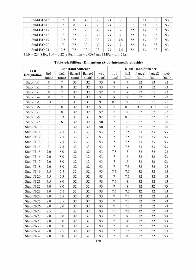
8/2/2019 Design of Bearing Stiffeners in Cold Formed C-Sections
http://slidepdf.com/reader/full/design-of-bearing-stiffeners-in-cold-formed-c-sections 134/151
120
Stud-E/O-15 7 8 33 33 93 7 8 33 33 93
Stud-E/O-16 7 8 33 33 93 7 8 33 33 93
Stud-E/O-17 7 7.5 33 33 93 7 7.5 33 33 93
Stud-E/O-18 7 7.5 33 33 93 7 7.5 33 33 93
Stud-E/O-19 7.5 7.5 33 33 93 7.5 7.5 33 33 93
Stud-E/O-20 7 7.5 33 33 93 7 7.5 33 33 93
Stud-E/O-21 7.5 7.5 33 33 93 7.5 7.5 33 33 93
1 kN = 224.8 lbs, 1 N = 0.2248 lbs, 1 mm = 0.0394 in., 1 MPa = 0.145 ksi
Table A4: Stiffener Dimensions (Stud-Intermediate-Inside)
Left Hand Stiffener Right Hand StiffenerTest
Designation lip1
(mm)
lip2
(mm)
flange1
(mm)
flange2
(mm)
web
(mm)
lip1
(mm)
lip2
(mm)
flange1
(mm)
flange2
(mm)
web
(mm)
Stud-I/I-1 8 7 33 32 93 8 7 32 33 92
Stud-I/I-2 7 8 32 32 93 7 8 33 32 93
Stud-I/I-3 8 7 32 32 92 7 8 32 31 92
Stud-I/I-4 8 7 31 32 91 8 7 32 32 92Stud-I/I-5 8.3 7 31 31 91 8.3 7 31 31 91
Stud-I/I-6 7 8 32 32 91 7 8.3 31.5 31.5 91
Stud-I/I-7 7 8 32 32 92 7 8 32 32 92
Stud-I/I-8 7 8.3 31 31 92 7 8.3 31 32 92
Stud-I/I-9 7 6 32 32 90 7 6 32 32 90
Stud-I/I-10 7 7 32 32 90 7 6 32 32 90
Stud-I/I-11 7 7.5 33 33 93 7 7.5 33 33 93
Stud-I/I-12 7 7.5 33 33 93 7 7.5 33 33 93
Stud-I/I-13 7 7.5 33 33 93 7 7.5 33 33 93
Stud-I/I-14 7 7.5 33 33 93 7 7.5 33 33 93
Stud-I/I-15 7.0 8.0 32 32 93 7.5 7 32 32 93
Stud-I/I-16 7.0 8.0 32 32 93 7 8 32 32 93
Stud-I/I-17 7.0 8.0 32 32 93 7 8 32 32 93
Stud-I/I-18 7.0 8.0 32 32 93 7 7.5 32 32 93
Stud-I/I-19 7.5 7.5 32 32 93 7.5 7.5 32 32 93
Stud-I/I-20 7.5 7.5 32 32 93 7 7.5 32 32 93
Stud-I/I-21 7.5 8.0 32 32 93 7.5 8 32 32 93
Stud-I/I-22 7.0 8.0 32 32 93 7 8 32 32 93
Stud-I/I-23 7.0 7.5 32 32 93 7.5 7.5 32 32 93
Stud-I/I-24 7.0 7.5 32 32 93 7 7.5 32 32 93
Stud-I/I-25 7.0 7.5 32 32 93 7 7.5 32 32 93
Stud-I/I-26 7.0 8.0 32 32 93 7 7.5 32 32 93
Stud-I/I-27 7.5 7.5 32 32 93 7.5 7.5 32 32 93
Stud-I/I-28 7.0 8.0 32 32 93 7 8 32 32 93
Stud-I/I-29 7.0 8.0 32 32 93 7 8 32 32 93
Stud-I/I-30 7.0 8.0 32 32 93 7 8 32 32 93
Stud-I/I-31 7.0 7.5 32 32 93 7 7.5 32 32 93
Stud-I/I-32 7.0 8.0 32 32 93 7 8 32 32 93
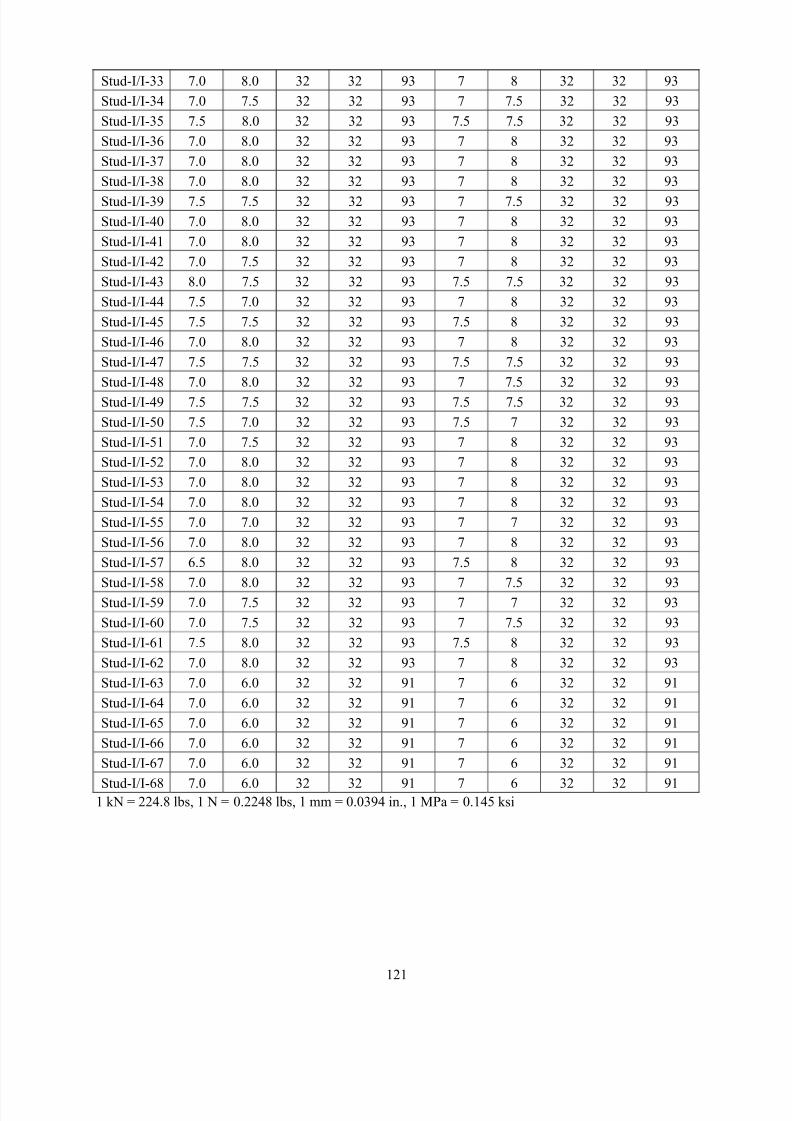
8/2/2019 Design of Bearing Stiffeners in Cold Formed C-Sections
http://slidepdf.com/reader/full/design-of-bearing-stiffeners-in-cold-formed-c-sections 135/151
121
Stud-I/I-33 7.0 8.0 32 32 93 7 8 32 32 93
Stud-I/I-34 7.0 7.5 32 32 93 7 7.5 32 32 93
Stud-I/I-35 7.5 8.0 32 32 93 7.5 7.5 32 32 93
Stud-I/I-36 7.0 8.0 32 32 93 7 8 32 32 93
Stud-I/I-37 7.0 8.0 32 32 93 7 8 32 32 93
Stud-I/I-38 7.0 8.0 32 32 93 7 8 32 32 93
Stud-I/I-39 7.5 7.5 32 32 93 7 7.5 32 32 93
Stud-I/I-40 7.0 8.0 32 32 93 7 8 32 32 93
Stud-I/I-41 7.0 8.0 32 32 93 7 8 32 32 93
Stud-I/I-42 7.0 7.5 32 32 93 7 8 32 32 93
Stud-I/I-43 8.0 7.5 32 32 93 7.5 7.5 32 32 93
Stud-I/I-44 7.5 7.0 32 32 93 7 8 32 32 93
Stud-I/I-45 7.5 7.5 32 32 93 7.5 8 32 32 93
Stud-I/I-46 7.0 8.0 32 32 93 7 8 32 32 93
Stud-I/I-47 7.5 7.5 32 32 93 7.5 7.5 32 32 93
Stud-I/I-48 7.0 8.0 32 32 93 7 7.5 32 32 93
Stud-I/I-49 7.5 7.5 32 32 93 7.5 7.5 32 32 93
Stud-I/I-50 7.5 7.0 32 32 93 7.5 7 32 32 93
Stud-I/I-51 7.0 7.5 32 32 93 7 8 32 32 93
Stud-I/I-52 7.0 8.0 32 32 93 7 8 32 32 93
Stud-I/I-53 7.0 8.0 32 32 93 7 8 32 32 93
Stud-I/I-54 7.0 8.0 32 32 93 7 8 32 32 93
Stud-I/I-55 7.0 7.0 32 32 93 7 7 32 32 93
Stud-I/I-56 7.0 8.0 32 32 93 7 8 32 32 93
Stud-I/I-57 6.5 8.0 32 32 93 7.5 8 32 32 93
Stud-I/I-58 7.0 8.0 32 32 93 7 7.5 32 32 93Stud-I/I-59 7.0 7.5 32 32 93 7 7 32 32 93
Stud-I/I-60 7.0 7.5 32 32 93 7 7.5 32 32 93
Stud-I/I-61 7.5 8.0 32 32 93 7.5 8 32 32 93
Stud-I/I-62 7.0 8.0 32 32 93 7 8 32 32 93
Stud-I/I-63 7.0 6.0 32 32 91 7 6 32 32 91
Stud-I/I-64 7.0 6.0 32 32 91 7 6 32 32 91
Stud-I/I-65 7.0 6.0 32 32 91 7 6 32 32 91
Stud-I/I-66 7.0 6.0 32 32 91 7 6 32 32 91
Stud-I/I-67 7.0 6.0 32 32 91 7 6 32 32 91
Stud-I/I-68 7.0 6.0 32 32 91 7 6 32 32 911 kN = 224.8 lbs, 1 N = 0.2248 lbs, 1 mm = 0.0394 in., 1 MPa = 0.145 ksi
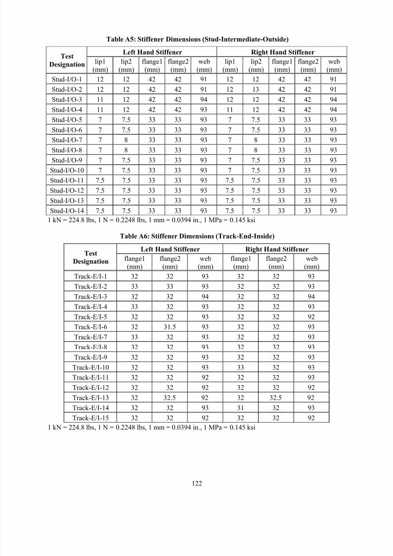
8/2/2019 Design of Bearing Stiffeners in Cold Formed C-Sections
http://slidepdf.com/reader/full/design-of-bearing-stiffeners-in-cold-formed-c-sections 136/151
122
Table A5: Stiffener Dimensions (Stud-Intermediate-Outside)
Left Hand Stiffener Right Hand StiffenerTest
Designation lip1
(mm)
lip2
(mm)
flange1
(mm)
flange2
(mm)
web
(mm)
lip1
(mm)
lip2
(mm)
flange1
(mm)
flange2
(mm)
web
(mm)
Stud-I/O-1 12 12 42 42 91 12 12 42 42 91
Stud-I/O-2 12 12 42 42 91 12 13 42 42 91
Stud-I/O-3 11 12 42 42 94 12 12 42 42 94
Stud-I/O-4 11 12 42 42 93 11 12 42 42 94
Stud-I/O-5 7 7.5 33 33 93 7 7.5 33 33 93
Stud-I/O-6 7 7.5 33 33 93 7 7.5 33 33 93
Stud-I/O-7 7 8 33 33 93 7 8 33 33 93
Stud-I/O-8 7 8 33 33 93 7 8 33 33 93
Stud-I/O-9 7 7.5 33 33 93 7 7.5 33 33 93
Stud-I/O-10 7 7.5 33 33 93 7 7.5 33 33 93
Stud-I/O-11 7.5 7.5 33 33 93 7.5 7.5 33 33 93
Stud-I/O-12 7.5 7.5 33 33 93 7.5 7.5 33 33 93
Stud-I/O-13 7.5 7.5 33 33 93 7.5 7.5 33 33 93
Stud-I/O-14 7.5 7.5 33 33 93 7.5 7.5 33 33 93
1 kN = 224.8 lbs, 1 N = 0.2248 lbs, 1 mm = 0.0394 in., 1 MPa = 0.145 ksi
Table A6: Stiffener Dimensions (Track-End-Inside)
Left Hand Stiffener Right Hand StiffenerTest
Designation flange1
(mm)
flange2
(mm)
web
(mm)
flange1
(mm)
flange2
(mm)
web
(mm)
Track-E/I-1 32 32 93 32 32 93
Track-E/I-2 33 33 93 32 32 93
Track-E/I-3 32 32 94 32 32 94
Track-E/I-4 33 32 93 32 32 93
Track-E/I-5 32 32 93 32 32 92
Track-E/I-6 32 31.5 93 32 32 93
Track-E/I-7 33 32 93 32 32 93
Track-E/I-8 32 32 93 32 32 93
Track-E/I-9 32 32 93 32 32 93
Track-E/I-10 32 32 93 33 32 93
Track-E/I-11 32 32 92 32 32 93
Track-E/I-12 32 32 92 32 32 92Track-E/I-13 32 32.5 92 32 32.5 92
Track-E/I-14 32 32 93 31 32 93
Track-E/I-15 32 32 92 32 32 92
1 kN = 224.8 lbs, 1 N = 0.2248 lbs, 1 mm = 0.0394 in., 1 MPa = 0.145 ksi
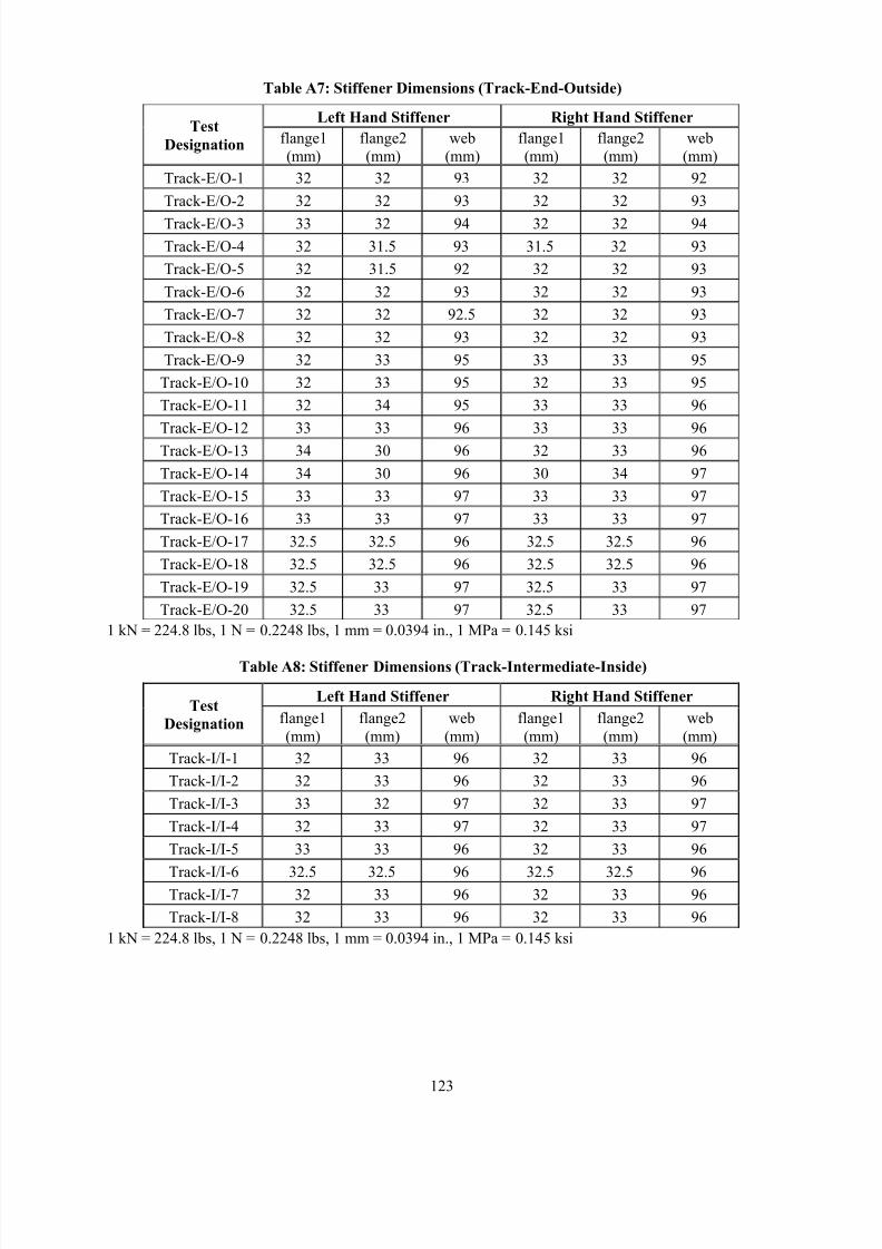
8/2/2019 Design of Bearing Stiffeners in Cold Formed C-Sections
http://slidepdf.com/reader/full/design-of-bearing-stiffeners-in-cold-formed-c-sections 137/151
123
Table A7: Stiffener Dimensions (Track-End-Outside)
Left Hand Stiffener Right Hand StiffenerTest
Designation flange1
(mm)
flange2
(mm)
web
(mm)
flange1
(mm)
flange2
(mm)
web
(mm)
Track-E/O-1 32 32 93 32 32 92
Track-E/O-2 32 32 93 32 32 93
Track-E/O-3 33 32 94 32 32 94
Track-E/O-4 32 31.5 93 31.5 32 93
Track-E/O-5 32 31.5 92 32 32 93
Track-E/O-6 32 32 93 32 32 93
Track-E/O-7 32 32 92.5 32 32 93
Track-E/O-8 32 32 93 32 32 93
Track-E/O-9 32 33 95 33 33 95
Track-E/O-10 32 33 95 32 33 95
Track-E/O-11 32 34 95 33 33 96
Track-E/O-12 33 33 96 33 33 96
Track-E/O-13 34 30 96 32 33 96
Track-E/O-14 34 30 96 30 34 97
Track-E/O-15 33 33 97 33 33 97
Track-E/O-16 33 33 97 33 33 97
Track-E/O-17 32.5 32.5 96 32.5 32.5 96
Track-E/O-18 32.5 32.5 96 32.5 32.5 96
Track-E/O-19 32.5 33 97 32.5 33 97
Track-E/O-20 32.5 33 97 32.5 33 97
1 kN = 224.8 lbs, 1 N = 0.2248 lbs, 1 mm = 0.0394 in., 1 MPa = 0.145 ksi
Table A8: Stiffener Dimensions (Track-Intermediate-Inside)
Left Hand Stiffener Right Hand StiffenerTest
Designation flange1
(mm)
flange2
(mm)
web
(mm)
flange1
(mm)
flange2
(mm)
web
(mm)
Track-I/I-1 32 33 96 32 33 96
Track-I/I-2 32 33 96 32 33 96
Track-I/I-3 33 32 97 32 33 97
Track-I/I-4 32 33 97 32 33 97
Track-I/I-5 33 33 96 32 33 96
Track-I/I-6 32.5 32.5 96 32.5 32.5 96Track-I/I-7 32 33 96 32 33 96
Track-I/I-8 32 33 96 32 33 96
1 kN = 224.8 lbs, 1 N = 0.2248 lbs, 1 mm = 0.0394 in., 1 MPa = 0.145 ksi
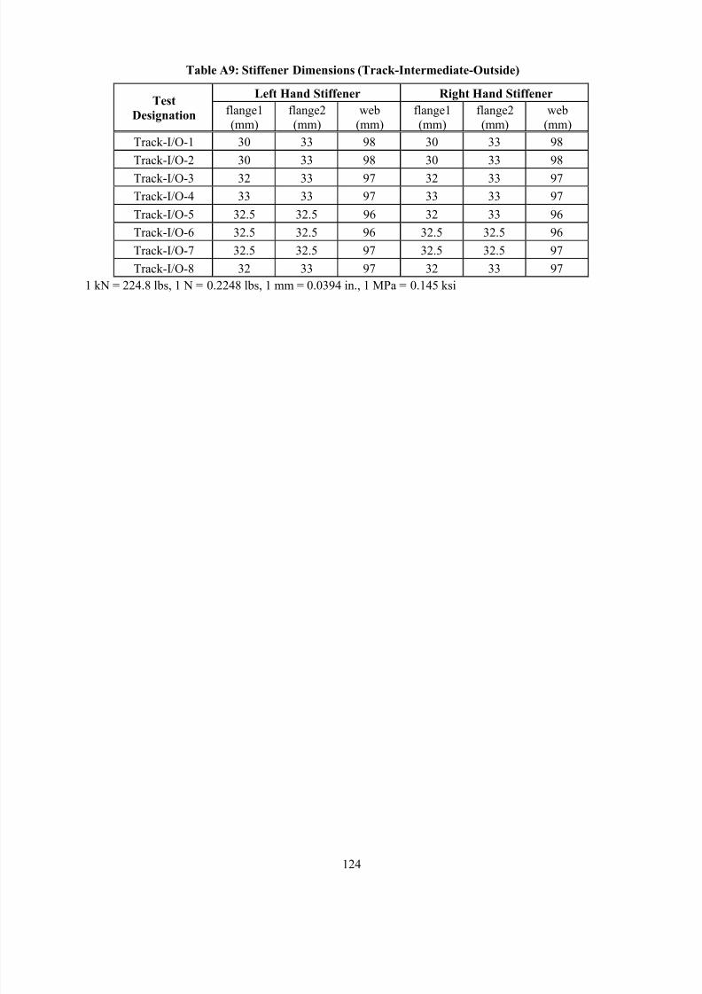
8/2/2019 Design of Bearing Stiffeners in Cold Formed C-Sections
http://slidepdf.com/reader/full/design-of-bearing-stiffeners-in-cold-formed-c-sections 138/151
124
Table A9: Stiffener Dimensions (Track-Intermediate-Outside)
Left Hand Stiffener Right Hand StiffenerTest
Designation flange1
(mm)
flange2
(mm)
web
(mm)
flange1
(mm)
flange2
(mm)
web
(mm)
Track-I/O-1 30 33 98 30 33 98
Track-I/O-2 30 33 98 30 33 98
Track-I/O-3 32 33 97 32 33 97
Track-I/O-4 33 33 97 33 33 97
Track-I/O-5 32.5 32.5 96 32 33 96
Track-I/O-6 32.5 32.5 96 32.5 32.5 96
Track-I/O-7 32.5 32.5 97 32.5 32.5 97
Track-I/O-8 32 33 97 32 33 97
1 kN = 224.8 lbs, 1 N = 0.2248 lbs, 1 mm = 0.0394 in., 1 MPa = 0.145 ksi

8/2/2019 Design of Bearing Stiffeners in Cold Formed C-Sections
http://slidepdf.com/reader/full/design-of-bearing-stiffeners-in-cold-formed-c-sections 139/151
125
APPENDIX B:
TESTED CAPACITIES AND CALCULATED PROPERTIES
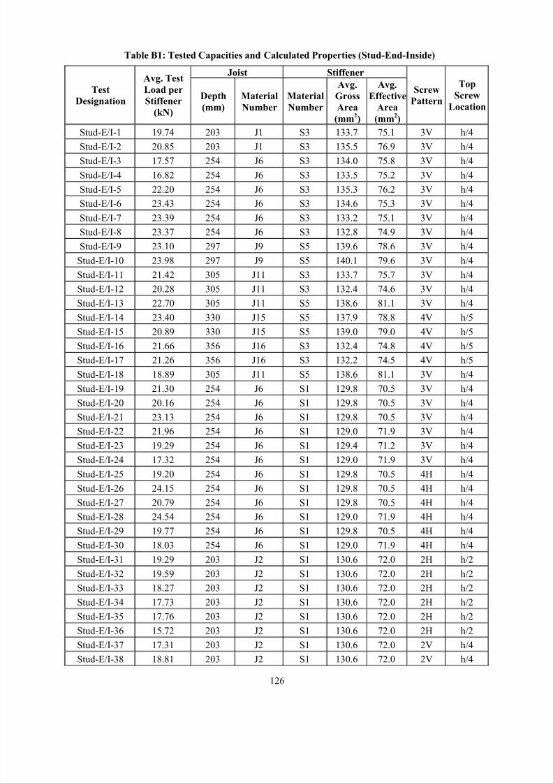
8/2/2019 Design of Bearing Stiffeners in Cold Formed C-Sections
http://slidepdf.com/reader/full/design-of-bearing-stiffeners-in-cold-formed-c-sections 140/151
126
Table B1: Tested Capacities and Calculated Properties (Stud-End-Inside)
Joist Stiffener
Test
Designation
Avg. Test
Load per
Stiffener
(kN)
Depth
(mm)
Material
Number
Material
Number
Avg.
Gross
Area
(mm2)
Avg.
Effective
Area
(mm2)
Screw
Pattern
Top
Screw
Location
Stud-E/I-1 19.74 203 J1 S3 133.7 75.1 3V h/4Stud-E/I-2 20.85 203 J1 S3 135.5 76.9 3V h/4
Stud-E/I-3 17.57 254 J6 S3 134.0 75.8 3V h/4
Stud-E/I-4 16.82 254 J6 S3 133.5 75.2 3V h/4
Stud-E/I-5 22.20 254 J6 S3 135.3 76.2 3V h/4
Stud-E/I-6 23.43 254 J6 S3 134.6 75.3 3V h/4
Stud-E/I-7 23.39 254 J6 S3 133.2 75.1 3V h/4
Stud-E/I-8 23.37 254 J6 S3 132.8 74.9 3V h/4
Stud-E/I-9 23.10 297 J9 S5 139.6 78.6 3V h/4
Stud-E/I-10 23.98 297 J9 S5 140.1 79.6 3V h/4
Stud-E/I-11 21.42 305 J11 S3 133.7 75.7 3V h/4Stud-E/I-12 20.28 305 J11 S3 132.4 74.6 3V h/4
Stud-E/I-13 22.70 305 J11 S5 138.6 81.1 3V h/4
Stud-E/I-14 23.40 330 J15 S5 137.9 78.8 4V h/5
Stud-E/I-15 20.89 330 J15 S5 139.0 79.0 4V h/5
Stud-E/I-16 21.66 356 J16 S3 132.4 74.8 4V h/5
Stud-E/I-17 21.26 356 J16 S3 132.2 74.5 4V h/5
Stud-E/I-18 18.89 305 J11 S5 138.6 81.1 3V h/4
Stud-E/I-19 21.30 254 J6 S1 129.8 70.5 3V h/4
Stud-E/I-20 20.16 254 J6 S1 129.8 70.5 3V h/4
Stud-E/I-21 23.13 254 J6 S1 129.8 70.5 3V h/4
Stud-E/I-22 21.96 254 J6 S1 129.0 71.9 3V h/4
Stud-E/I-23 19.29 254 J6 S1 129.4 71.2 3V h/4
Stud-E/I-24 17.32 254 J6 S1 129.0 71.9 3V h/4
Stud-E/I-25 19.20 254 J6 S1 129.8 70.5 4H h/4
Stud-E/I-26 24.15 254 J6 S1 129.8 70.5 4H h/4
Stud-E/I-27 20.79 254 J6 S1 129.8 70.5 4H h/4
Stud-E/I-28 24.54 254 J6 S1 129.0 71.9 4H h/4
Stud-E/I-29 19.77 254 J6 S1 129.8 70.5 4H h/4
Stud-E/I-30 18.03 254 J6 S1 129.0 71.9 4H h/4Stud-E/I-31 19.29 203 J2 S1 130.6 72.0 2H h/2
Stud-E/I-32 19.59 203 J2 S1 130.6 72.0 2H h/2
Stud-E/I-33 18.27 203 J2 S1 130.6 72.0 2H h/2
Stud-E/I-34 17.73 203 J2 S1 130.6 72.0 2H h/2
Stud-E/I-35 17.76 203 J2 S1 130.6 72.0 2H h/2
Stud-E/I-36 15.72 203 J2 S1 130.6 72.0 2H h/2
Stud-E/I-37 17.31 203 J2 S1 130.6 72.0 2V h/4
Stud-E/I-38 18.81 203 J2 S1 130.6 72.0 2V h/4
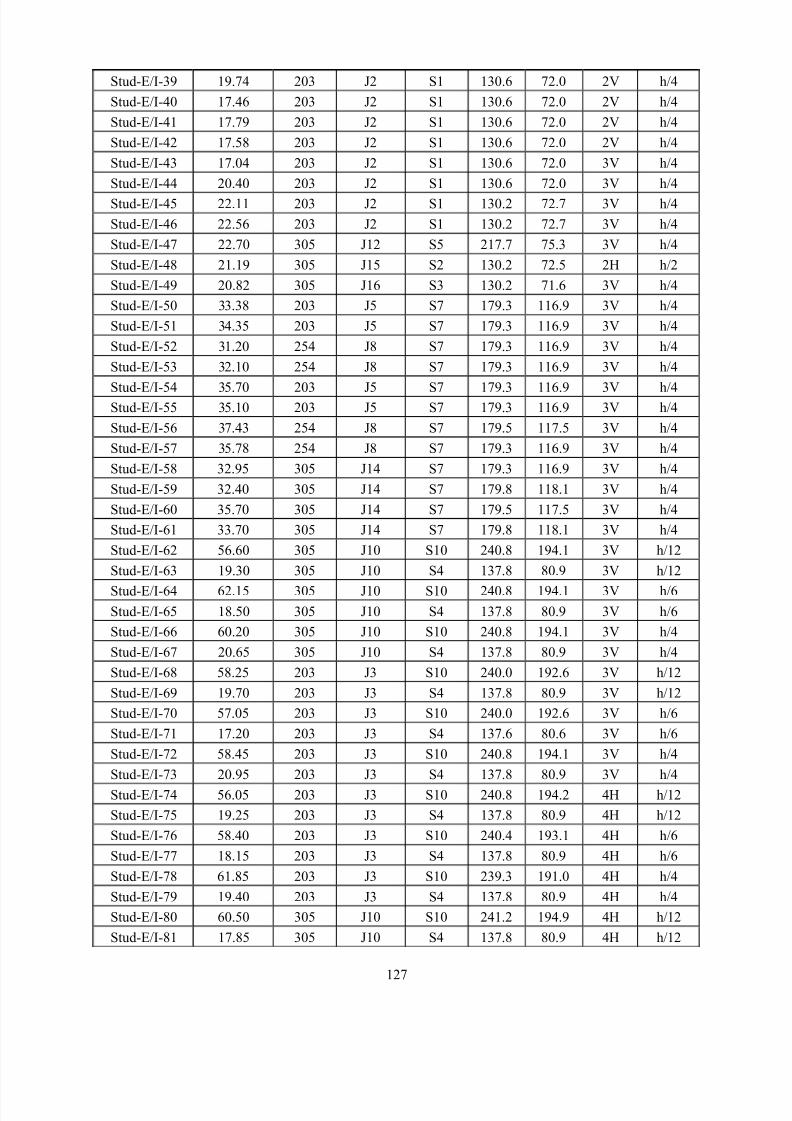
8/2/2019 Design of Bearing Stiffeners in Cold Formed C-Sections
http://slidepdf.com/reader/full/design-of-bearing-stiffeners-in-cold-formed-c-sections 141/151
127
Stud-E/I-39 19.74 203 J2 S1 130.6 72.0 2V h/4
Stud-E/I-40 17.46 203 J2 S1 130.6 72.0 2V h/4
Stud-E/I-41 17.79 203 J2 S1 130.6 72.0 2V h/4
Stud-E/I-42 17.58 203 J2 S1 130.6 72.0 2V h/4
Stud-E/I-43 17.04 203 J2 S1 130.6 72.0 3V h/4
Stud-E/I-44 20.40 203 J2 S1 130.6 72.0 3V h/4
Stud-E/I-45 22.11 203 J2 S1 130.2 72.7 3V h/4
Stud-E/I-46 22.56 203 J2 S1 130.2 72.7 3V h/4
Stud-E/I-47 22.70 305 J12 S5 217.7 75.3 3V h/4
Stud-E/I-48 21.19 305 J15 S2 130.2 72.5 2H h/2
Stud-E/I-49 20.82 305 J16 S3 130.2 71.6 3V h/4
Stud-E/I-50 33.38 203 J5 S7 179.3 116.9 3V h/4
Stud-E/I-51 34.35 203 J5 S7 179.3 116.9 3V h/4
Stud-E/I-52 31.20 254 J8 S7 179.3 116.9 3V h/4
Stud-E/I-53 32.10 254 J8 S7 179.3 116.9 3V h/4
Stud-E/I-54 35.70 203 J5 S7 179.3 116.9 3V h/4Stud-E/I-55 35.10 203 J5 S7 179.3 116.9 3V h/4
Stud-E/I-56 37.43 254 J8 S7 179.5 117.5 3V h/4
Stud-E/I-57 35.78 254 J8 S7 179.3 116.9 3V h/4
Stud-E/I-58 32.95 305 J14 S7 179.3 116.9 3V h/4
Stud-E/I-59 32.40 305 J14 S7 179.8 118.1 3V h/4
Stud-E/I-60 35.70 305 J14 S7 179.5 117.5 3V h/4
Stud-E/I-61 33.70 305 J14 S7 179.8 118.1 3V h/4
Stud-E/I-62 56.60 305 J10 S10 240.8 194.1 3V h/12
Stud-E/I-63 19.30 305 J10 S4 137.8 80.9 3V h/12
Stud-E/I-64 62.15 305 J10 S10 240.8 194.1 3V h/6
Stud-E/I-65 18.50 305 J10 S4 137.8 80.9 3V h/6
Stud-E/I-66 60.20 305 J10 S10 240.8 194.1 3V h/4
Stud-E/I-67 20.65 305 J10 S4 137.8 80.9 3V h/4
Stud-E/I-68 58.25 203 J3 S10 240.0 192.6 3V h/12
Stud-E/I-69 19.70 203 J3 S4 137.8 80.9 3V h/12
Stud-E/I-70 57.05 203 J3 S10 240.0 192.6 3V h/6
Stud-E/I-71 17.20 203 J3 S4 137.6 80.6 3V h/6
Stud-E/I-72 58.45 203 J3 S10 240.8 194.1 3V h/4
Stud-E/I-73 20.95 203 J3 S4 137.8 80.9 3V h/4
Stud-E/I-74 56.05 203 J3 S10 240.8 194.2 4H h/12
Stud-E/I-75 19.25 203 J3 S4 137.8 80.9 4H h/12
Stud-E/I-76 58.40 203 J3 S10 240.4 193.1 4H h/6
Stud-E/I-77 18.15 203 J3 S4 137.8 80.9 4H h/6
Stud-E/I-78 61.85 203 J3 S10 239.3 191.0 4H h/4
Stud-E/I-79 19.40 203 J3 S4 137.8 80.9 4H h/4
Stud-E/I-80 60.50 305 J10 S10 241.2 194.9 4H h/12
Stud-E/I-81 17.85 305 J10 S4 137.8 80.9 4H h/12
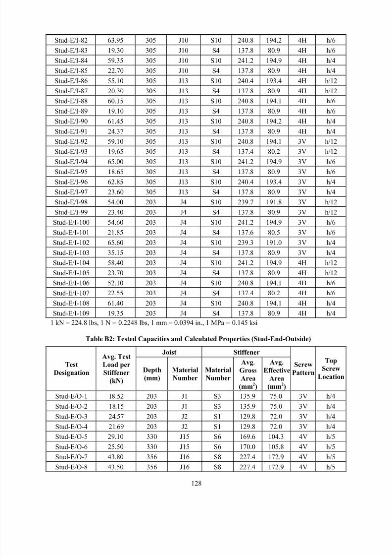
8/2/2019 Design of Bearing Stiffeners in Cold Formed C-Sections
http://slidepdf.com/reader/full/design-of-bearing-stiffeners-in-cold-formed-c-sections 142/151
128
Stud-E/I-82 63.95 305 J10 S10 240.8 194.2 4H h/6
Stud-E/I-83 19.30 305 J10 S4 137.8 80.9 4H h/6
Stud-E/I-84 59.35 305 J10 S10 241.2 194.9 4H h/4
Stud-E/I-85 22.70 305 J10 S4 137.8 80.9 4H h/4
Stud-E/I-86 55.10 305 J13 S10 240.4 193.4 4H h/12
Stud-E/I-87 20.30 305 J13 S4 137.8 80.9 4H h/12
Stud-E/I-88 60.15 305 J13 S10 240.8 194.1 4H h/6
Stud-E/I-89 19.10 305 J13 S4 137.8 80.9 4H h/6
Stud-E/I-90 61.45 305 J13 S10 240.8 194.2 4H h/4
Stud-E/I-91 24.37 305 J13 S4 137.8 80.9 4H h/4
Stud-E/I-92 59.10 305 J13 S10 240.8 194.1 3V h/12
Stud-E/I-93 19.65 305 J13 S4 137.4 80.2 3V h/12
Stud-E/I-94 65.00 305 J13 S10 241.2 194.9 3V h/6
Stud-E/I-95 18.65 305 J13 S4 137.8 80.9 3V h/6
Stud-E/I-96 62.85 305 J13 S10 240.4 193.4 3V h/4
Stud-E/I-97 23.60 305 J13 S4 137.8 80.9 3V h/4Stud-E/I-98 54.00 203 J4 S10 239.7 191.8 3V h/12
Stud-E/I-99 23.40 203 J4 S4 137.8 80.9 3V h/12
Stud-E/I-100 54.60 203 J4 S10 241.2 194.9 3V h/6
Stud-E/I-101 21.85 203 J4 S4 137.6 80.5 3V h/6
Stud-E/I-102 65.60 203 J4 S10 239.3 191.0 3V h/4
Stud-E/I-103 35.15 203 J4 S4 137.8 80.9 3V h/4
Stud-E/I-104 58.40 203 J4 S10 241.2 194.9 4H h/12
Stud-E/I-105 23.70 203 J4 S4 137.8 80.9 4H h/12
Stud-E/I-106 52.10 203 J4 S10 240.8 194.1 4H h/6
Stud-E/I-107 22.55 203 J4 S4 137.4 80.2 4H h/6
Stud-E/I-108 61.40 203 J4 S10 240.8 194.1 4H h/4
Stud-E/I-109 19.35 203 J4 S4 137.8 80.9 4H h/4
1 kN = 224.8 lbs, 1 N = 0.2248 lbs, 1 mm = 0.0394 in., 1 MPa = 0.145 ksi
Table B2: Tested Capacities and Calculated Properties (Stud-End-Outside)
Joist Stiffener
Test
Designation
Avg. Test
Load per
Stiffener
(kN)
Depth
(mm)
Material
Number
Material
Number
Avg.
Gross
Area
(mm
2
)
Avg.
Effective
Area
(mm
2
)
Screw
Pattern
Top
Screw
Location
Stud-E/O-1 18.52 203 J1 S3 135.9 75.0 3V h/4
Stud-E/O-2 18.15 203 J1 S3 135.9 75.0 3V h/4
Stud-E/O-3 24.57 203 J2 S1 129.8 72.0 3V h/4
Stud-E/O-4 21.69 203 J2 S1 129.8 72.0 3V h/4
Stud-E/O-5 29.10 330 J15 S6 169.6 104.3 4V h/5
Stud-E/O-6 25.50 330 J15 S6 170.0 105.8 4V h/5
Stud-E/O-7 43.80 356 J16 S8 227.4 172.9 4V h/5
Stud-E/O-8 43.50 356 J16 S8 227.4 172.9 4V h/5
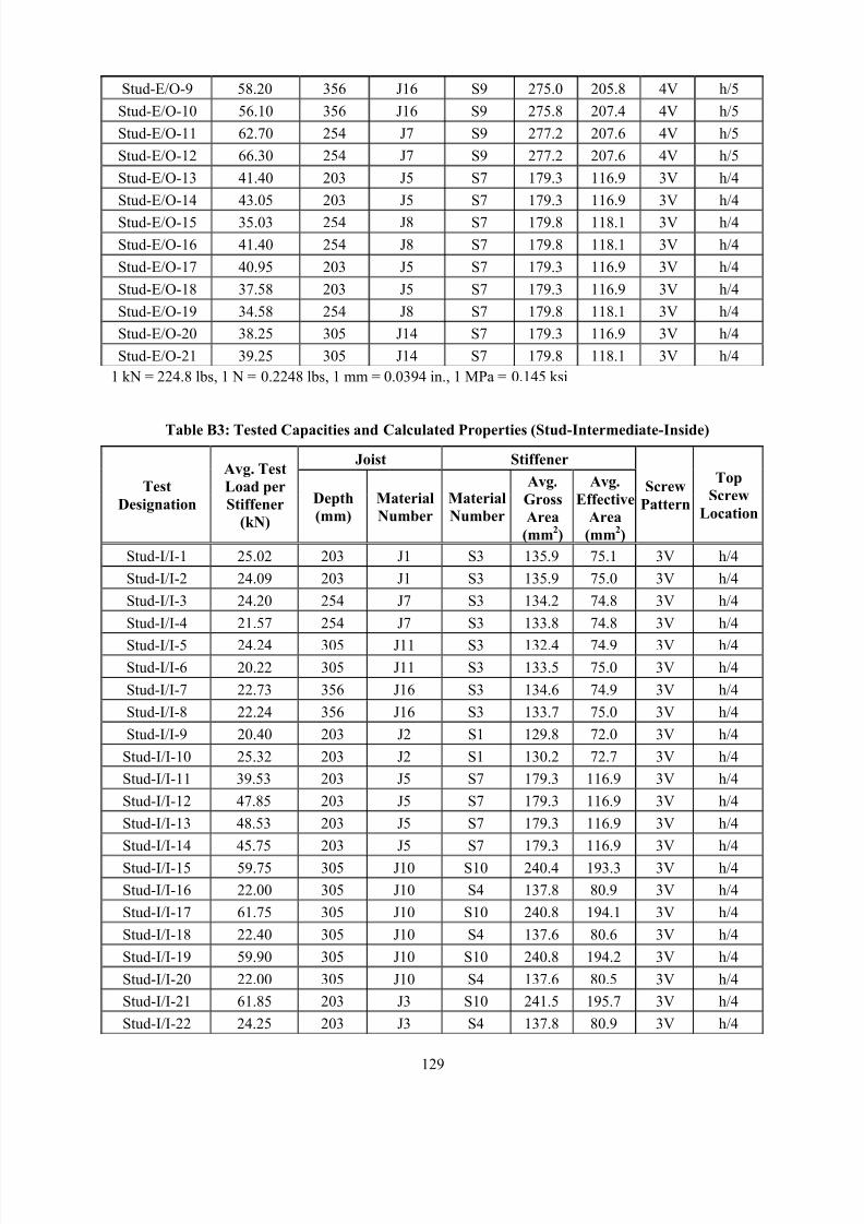
8/2/2019 Design of Bearing Stiffeners in Cold Formed C-Sections
http://slidepdf.com/reader/full/design-of-bearing-stiffeners-in-cold-formed-c-sections 143/151
129
Stud-E/O-9 58.20 356 J16 S9 275.0 205.8 4V h/5
Stud-E/O-10 56.10 356 J16 S9 275.8 207.4 4V h/5
Stud-E/O-11 62.70 254 J7 S9 277.2 207.6 4V h/5
Stud-E/O-12 66.30 254 J7 S9 277.2 207.6 4V h/5
Stud-E/O-13 41.40 203 J5 S7 179.3 116.9 3V h/4
Stud-E/O-14 43.05 203 J5 S7 179.3 116.9 3V h/4
Stud-E/O-15 35.03 254 J8 S7 179.8 118.1 3V h/4
Stud-E/O-16 41.40 254 J8 S7 179.8 118.1 3V h/4
Stud-E/O-17 40.95 203 J5 S7 179.3 116.9 3V h/4
Stud-E/O-18 37.58 203 J5 S7 179.3 116.9 3V h/4
Stud-E/O-19 34.58 254 J8 S7 179.8 118.1 3V h/4
Stud-E/O-20 38.25 305 J14 S7 179.3 116.9 3V h/4
Stud-E/O-21 39.25 305 J14 S7 179.8 118.1 3V h/4
1 kN = 224.8 lbs, 1 N = 0.2248 lbs, 1 mm = 0.0394 in., 1 MPa = 0.145 ksi
Table B3: Tested Capacities and Calculated Properties (Stud-Intermediate-Inside)
Joist Stiffener
Test
Designation
Avg. Test
Load per
Stiffener
(kN)
Depth
(mm)
Material
Number
Material
Number
Avg.
Gross
Area
(mm2)
Avg.
Effective
Area
(mm2)
Screw
Pattern
Top
Screw
Location
Stud-I/I-1 25.02 203 J1 S3 135.9 75.1 3V h/4
Stud-I/I-2 24.09 203 J1 S3 135.9 75.0 3V h/4
Stud-I/I-3 24.20 254 J7 S3 134.2 74.8 3V h/4
Stud-I/I-4 21.57 254 J7 S3 133.8 74.8 3V h/4
Stud-I/I-5 24.24 305 J11 S3 132.4 74.9 3V h/4
Stud-I/I-6 20.22 305 J11 S3 133.5 75.0 3V h/4
Stud-I/I-7 22.73 356 J16 S3 134.6 74.9 3V h/4
Stud-I/I-8 22.24 356 J16 S3 133.7 75.0 3V h/4
Stud-I/I-9 20.40 203 J2 S1 129.8 72.0 3V h/4
Stud-I/I-10 25.32 203 J2 S1 130.2 72.7 3V h/4
Stud-I/I-11 39.53 203 J5 S7 179.3 116.9 3V h/4
Stud-I/I-12 47.85 203 J5 S7 179.3 116.9 3V h/4
Stud-I/I-13 48.53 203 J5 S7 179.3 116.9 3V h/4
Stud-I/I-14 45.75 203 J5 S7 179.3 116.9 3V h/4
Stud-I/I-15 59.75 305 J10 S10 240.4 193.3 3V h/4
Stud-I/I-16 22.00 305 J10 S4 137.8 80.9 3V h/4
Stud-I/I-17 61.75 305 J10 S10 240.8 194.1 3V h/4
Stud-I/I-18 22.40 305 J10 S4 137.6 80.6 3V h/4
Stud-I/I-19 59.90 305 J10 S10 240.8 194.2 3V h/4
Stud-I/I-20 22.00 305 J10 S4 137.6 80.5 3V h/4
Stud-I/I-21 61.85 203 J3 S10 241.5 195.7 3V h/4
Stud-I/I-22 24.25 203 J3 S4 137.8 80.9 3V h/4
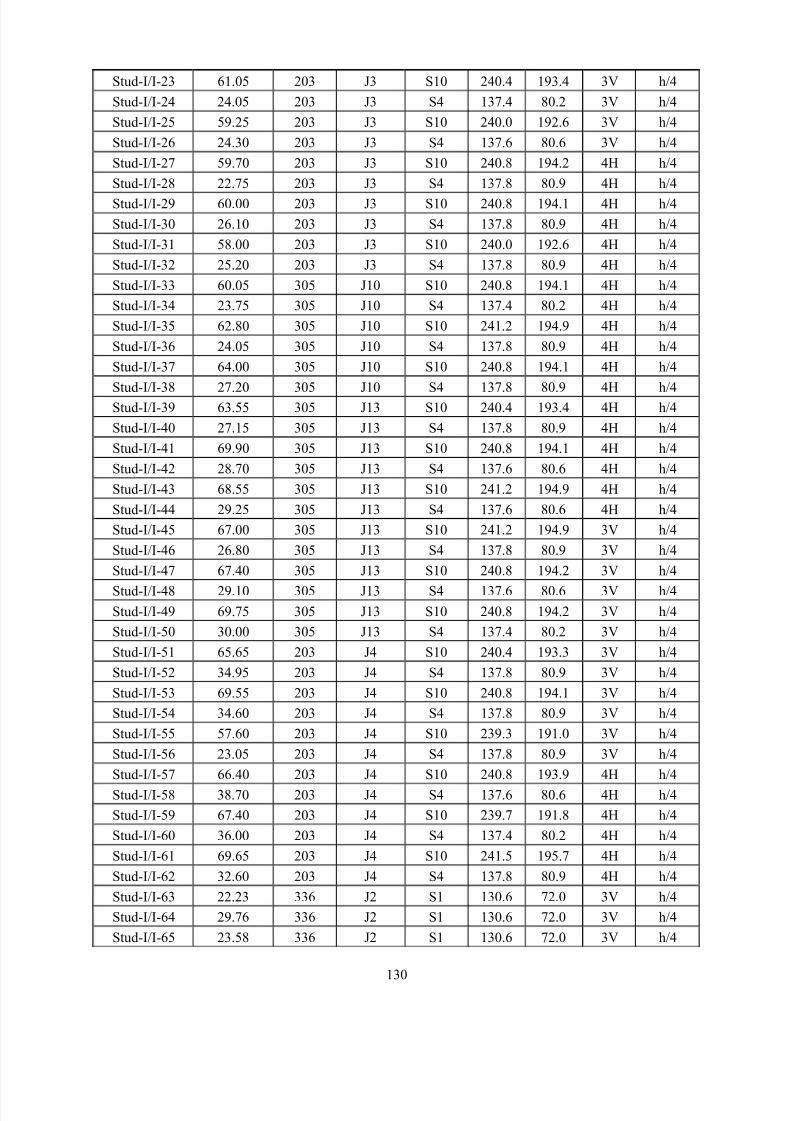
8/2/2019 Design of Bearing Stiffeners in Cold Formed C-Sections
http://slidepdf.com/reader/full/design-of-bearing-stiffeners-in-cold-formed-c-sections 144/151
130
Stud-I/I-23 61.05 203 J3 S10 240.4 193.4 3V h/4
Stud-I/I-24 24.05 203 J3 S4 137.4 80.2 3V h/4
Stud-I/I-25 59.25 203 J3 S10 240.0 192.6 3V h/4
Stud-I/I-26 24.30 203 J3 S4 137.6 80.6 3V h/4
Stud-I/I-27 59.70 203 J3 S10 240.8 194.2 4H h/4
Stud-I/I-28 22.75 203 J3 S4 137.8 80.9 4H h/4
Stud-I/I-29 60.00 203 J3 S10 240.8 194.1 4H h/4
Stud-I/I-30 26.10 203 J3 S4 137.8 80.9 4H h/4
Stud-I/I-31 58.00 203 J3 S10 240.0 192.6 4H h/4
Stud-I/I-32 25.20 203 J3 S4 137.8 80.9 4H h/4
Stud-I/I-33 60.05 305 J10 S10 240.8 194.1 4H h/4
Stud-I/I-34 23.75 305 J10 S4 137.4 80.2 4H h/4
Stud-I/I-35 62.80 305 J10 S10 241.2 194.9 4H h/4
Stud-I/I-36 24.05 305 J10 S4 137.8 80.9 4H h/4
Stud-I/I-37 64.00 305 J10 S10 240.8 194.1 4H h/4
Stud-I/I-38 27.20 305 J10 S4 137.8 80.9 4H h/4Stud-I/I-39 63.55 305 J13 S10 240.4 193.4 4H h/4
Stud-I/I-40 27.15 305 J13 S4 137.8 80.9 4H h/4
Stud-I/I-41 69.90 305 J13 S10 240.8 194.1 4H h/4
Stud-I/I-42 28.70 305 J13 S4 137.6 80.6 4H h/4
Stud-I/I-43 68.55 305 J13 S10 241.2 194.9 4H h/4
Stud-I/I-44 29.25 305 J13 S4 137.6 80.6 4H h/4
Stud-I/I-45 67.00 305 J13 S10 241.2 194.9 3V h/4
Stud-I/I-46 26.80 305 J13 S4 137.8 80.9 3V h/4
Stud-I/I-47 67.40 305 J13 S10 240.8 194.2 3V h/4
Stud-I/I-48 29.10 305 J13 S4 137.6 80.6 3V h/4
Stud-I/I-49 69.75 305 J13 S10 240.8 194.2 3V h/4
Stud-I/I-50 30.00 305 J13 S4 137.4 80.2 3V h/4
Stud-I/I-51 65.65 203 J4 S10 240.4 193.3 3V h/4
Stud-I/I-52 34.95 203 J4 S4 137.8 80.9 3V h/4
Stud-I/I-53 69.55 203 J4 S10 240.8 194.1 3V h/4
Stud-I/I-54 34.60 203 J4 S4 137.8 80.9 3V h/4
Stud-I/I-55 57.60 203 J4 S10 239.3 191.0 3V h/4
Stud-I/I-56 23.05 203 J4 S4 137.8 80.9 3V h/4
Stud-I/I-57 66.40 203 J4 S10 240.8 193.9 4H h/4
Stud-I/I-58 38.70 203 J4 S4 137.6 80.6 4H h/4
Stud-I/I-59 67.40 203 J4 S10 239.7 191.8 4H h/4
Stud-I/I-60 36.00 203 J4 S4 137.4 80.2 4H h/4
Stud-I/I-61 69.65 203 J4 S10 241.5 195.7 4H h/4
Stud-I/I-62 32.60 203 J4 S4 137.8 80.9 4H h/4
Stud-I/I-63 22.23 336 J2 S1 130.6 72.0 3V h/4
Stud-I/I-64 29.76 336 J2 S1 130.6 72.0 3V h/4
Stud-I/I-65 23.58 336 J2 S1 130.6 72.0 3V h/4
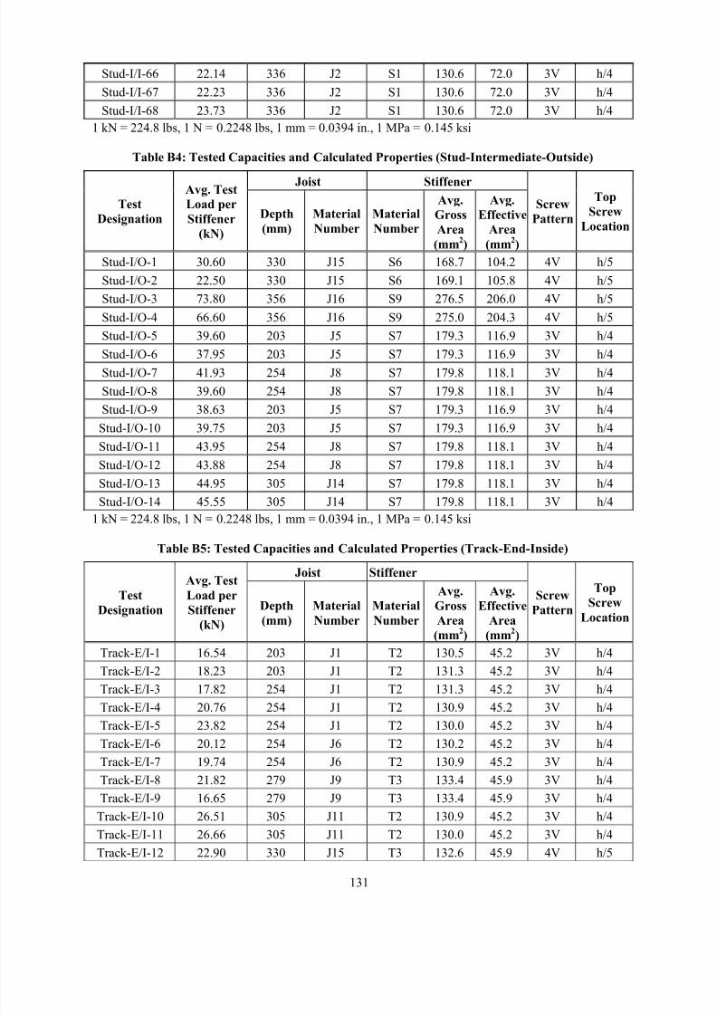
8/2/2019 Design of Bearing Stiffeners in Cold Formed C-Sections
http://slidepdf.com/reader/full/design-of-bearing-stiffeners-in-cold-formed-c-sections 145/151
131
Stud-I/I-66 22.14 336 J2 S1 130.6 72.0 3V h/4
Stud-I/I-67 22.23 336 J2 S1 130.6 72.0 3V h/4
Stud-I/I-68 23.73 336 J2 S1 130.6 72.0 3V h/4
1 kN = 224.8 lbs, 1 N = 0.2248 lbs, 1 mm = 0.0394 in., 1 MPa = 0.145 ksi
Table B4: Tested Capacities and Calculated Properties (Stud-Intermediate-Outside)
Joist Stiffener
Test
Designation
Avg. Test
Load per
Stiffener
(kN)
Depth
(mm)
Material
Number
Material
Number
Avg.
Gross
Area
(mm2)
Avg.
Effective
Area
(mm2)
Screw
Pattern
Top
Screw
Location
Stud-I/O-1 30.60 330 J15 S6 168.7 104.2 4V h/5
Stud-I/O-2 22.50 330 J15 S6 169.1 105.8 4V h/5
Stud-I/O-3 73.80 356 J16 S9 276.5 206.0 4V h/5
Stud-I/O-4 66.60 356 J16 S9 275.0 204.3 4V h/5
Stud-I/O-5 39.60 203 J5 S7 179.3 116.9 3V h/4
Stud-I/O-6 37.95 203 J5 S7 179.3 116.9 3V h/4Stud-I/O-7 41.93 254 J8 S7 179.8 118.1 3V h/4
Stud-I/O-8 39.60 254 J8 S7 179.8 118.1 3V h/4
Stud-I/O-9 38.63 203 J5 S7 179.3 116.9 3V h/4
Stud-I/O-10 39.75 203 J5 S7 179.3 116.9 3V h/4
Stud-I/O-11 43.95 254 J8 S7 179.8 118.1 3V h/4
Stud-I/O-12 43.88 254 J8 S7 179.8 118.1 3V h/4
Stud-I/O-13 44.95 305 J14 S7 179.8 118.1 3V h/4
Stud-I/O-14 45.55 305 J14 S7 179.8 118.1 3V h/4
1 kN = 224.8 lbs, 1 N = 0.2248 lbs, 1 mm = 0.0394 in., 1 MPa = 0.145 ksi
Table B5: Tested Capacities and Calculated Properties (Track-End-Inside)
Joist Stiffener
Test
Designation
Avg. Test
Load per
Stiffener
(kN)
Depth
(mm)
Material
Number
Material
Number
Avg.
Gross
Area
(mm2)
Avg.
Effective
Area
(mm2)
Screw
Pattern
Top
Screw
Location
Track-E/I-1 16.54 203 J1 T2 130.5 45.2 3V h/4
Track-E/I-2 18.23 203 J1 T2 131.3 45.2 3V h/4
Track-E/I-3 17.82 254 J1 T2 131.3 45.2 3V h/4
Track-E/I-4 20.76 254 J1 T2 130.9 45.2 3V h/4Track-E/I-5 23.82 254 J1 T2 130.0 45.2 3V h/4
Track-E/I-6 20.12 254 J6 T2 130.2 45.2 3V h/4
Track-E/I-7 19.74 254 J6 T2 130.9 45.2 3V h/4
Track-E/I-8 21.82 279 J9 T3 133.4 45.9 3V h/4
Track-E/I-9 16.65 279 J9 T3 133.4 45.9 3V h/4
Track-E/I-10 26.51 305 J11 T2 130.9 45.2 3V h/4
Track-E/I-11 26.66 305 J11 T2 130.0 45.2 3V h/4
Track-E/I-12 22.90 330 J15 T3 132.6 45.9 4V h/5
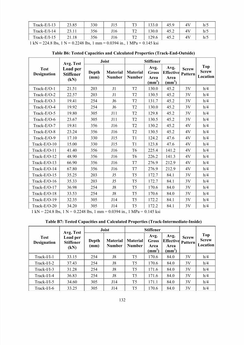
8/2/2019 Design of Bearing Stiffeners in Cold Formed C-Sections
http://slidepdf.com/reader/full/design-of-bearing-stiffeners-in-cold-formed-c-sections 146/151
132
Track-E/I-13 23.85 330 J15 T3 133.0 45.9 4V h/5
Track-E/I-14 23.11 356 J16 T2 130.0 45.2 4V h/5
Track-E/I-15 21.18 356 J16 T2 129.6 45.2 4V h/5
1 kN = 224.8 lbs, 1 N = 0.2248 lbs, 1 mm = 0.0394 in., 1 MPa = 0.145 ksi
Table B6: Tested Capacities and Calculated Properties (Track-End-Outside)
Joist Stiffener
Test
Designation
Avg. Test
Load per
Stiffener(kN)
Depth
(mm)
Material
Number
Material
Number
Avg.
Gross
Area
(mm2)
Avg.
Effective
Area
(mm2)
Screw
Pattern
Top
Screw
Location
Track-E/O-1 21.51 203 J1 T2 130.0 45.2 3V h/4
Track-E/O-2 22.57 203 J1 T2 130.5 45.2 3V h/4
Track-E/O-3 19.41 254 J6 T2 131.7 45.2 3V h/4
Track-E/O-4 19.92 254 J6 T2 130.0 45.2 3V h/4
Track-E/O-5 19.80 305 J11 T2 129.8 45.2 3V h/4
Track-E/O-6 23.67 305 J11 T2 130.5 45.2 3V h/4Track-E/O-7 19.81 356 J16 T2 130.2 45.2 4V h/4
Track-E/O-8 23.24 356 J16 T2 130.5 45.2 4V h/4
Track-E/O-9 17.10 330 J15 T1 124.2 47.6 4V h/4
Track-E/O-10 15.00 330 J15 T1 123.8 47.6 4V h/4
Track-E/O-11 41.40 356 J16 T6 225.4 141.2 4V h/4
Track-E/O-12 48.90 356 J16 T6 226.2 141.3 4V h/4
Track-E/O-13 66.90 356 J16 T7 276.9 212.9 4V h/4
Track-E/O-14 67.80 356 J16 T7 276.9 212.9 4V h/4
Track-E/O-15 35.25 203 J5 T5 172.7 84.1 3V h/4
Track-E/O-16 35.33 203 J5 T5 172.7 84.1 3V h/4Track-E/O-17 36.98 254 J8 T5 170.6 84.0 3V h/4
Track-E/O-18 33.53 254 J8 T5 170.6 84.0 3V h/4
Track-E/O-19 32.35 305 J14 T5 172.2 84.1 3V h/4
Track-E/O-20 34.20 305 J14 T5 172.2 84.1 3V h/4
1 kN = 224.8 lbs, 1 N = 0.2248 lbs, 1 mm = 0.0394 in., 1 MPa = 0.145 ksi
Table B7: Tested Capacities and Calculated Properties (Track-Intermediate-Inside)
Joist Stiffener
Test
Designation
Avg. Test
Load per
Stiffener(kN)
Depth(mm)
MaterialNumber
MaterialNumber
Avg.
GrossArea
(mm2)
Avg.
EffectiveArea
(mm2)
Screw
Pattern
Top
ScrewLocation
Track-I/I-1 33.15 254 J8 T5 170.6 84.0 3V h/4
Track-I/I-2 37.43 254 J8 T5 170.6 84.0 3V h/4
Track-I/I-3 31.28 254 J8 T5 171.6 84.0 3V h/4
Track-I/I-4 36.83 254 J8 T5 171.6 84.0 3V h/4
Track-I/I-5 34.60 305 J14 T5 171.1 84.0 3V h/4
Track-I/I-6 33.25 305 J14 T5 170.6 84.0 3V h/4
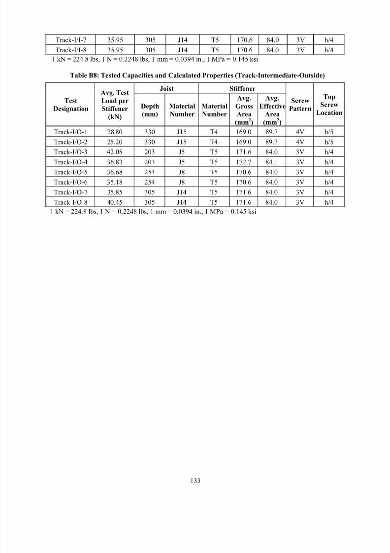
8/2/2019 Design of Bearing Stiffeners in Cold Formed C-Sections
http://slidepdf.com/reader/full/design-of-bearing-stiffeners-in-cold-formed-c-sections 147/151
133
Track-I/I-7 35.95 305 J14 T5 170.6 84.0 3V h/4
Track-I/I-8 35.95 305 J14 T5 170.6 84.0 3V h/4
1 kN = 224.8 lbs, 1 N = 0.2248 lbs, 1 mm = 0.0394 in., 1 MPa = 0.145 ksi
Table B8: Tested Capacities and Calculated Properties (Track-Intermediate-Outside)
Joist Stiffener
Test
Designation
Avg. Test
Load per
Stiffener
(kN)
Depth
(mm)
Material
Number
Material
Number
Avg.Gross
Area
(mm2)
Avg.Effective
Area
(mm2)
Screw
Pattern
TopScrew
Location
Track-I/O-1 28.80 330 J15 T4 169.0 89.7 4V h/5
Track-I/O-2 25.20 330 J15 T4 169.0 89.7 4V h/5
Track-I/O-3 42.08 203 J5 T5 171.6 84.0 3V h/4
Track-I/O-4 36.83 203 J5 T5 172.7 84.1 3V h/4
Track-I/O-5 36.68 254 J8 T5 170.6 84.0 3V h/4
Track-I/O-6 35.18 254 J8 T5 170.6 84.0 3V h/4
Track-I/O-7 35.85 305 J14 T5 171.6 84.0 3V h/4Track-I/O-8 40.45 305 J14 T5 171.6 84.0 3V h/4
1 kN = 224.8 lbs, 1 N = 0.2248 lbs, 1 mm = 0.0394 in., 1 MPa = 0.145 ksi
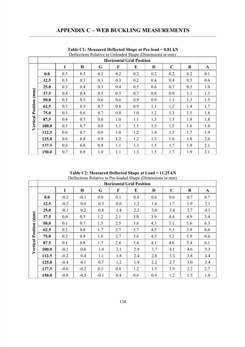
8/2/2019 Design of Bearing Stiffeners in Cold Formed C-Sections
http://slidepdf.com/reader/full/design-of-bearing-stiffeners-in-cold-formed-c-sections 148/151
134
APPENDIX C – WEB BUCKLING MEASUREMENTS
Table C1: Measured Deflected Shape at Pre-load = 0.81 kN
Deflections Relative to Unloaded Shape (Dimensions in mm)
Horizontal Grid PositionI H G F E D C B A
0.0 0.3 0.3 0.2 0.2 0.2 0.2 0.2 0.2 0.1
12.5 0.3 0.3 0.3 0.3 0.2 0.4 0.4 0.5 0.6
25.0 0.3 0.4 0.3 0.4 0.5 0.6 0.7 0.5 1.0
37.5 0.4 0.4 0.5 0.5 0.7 0.8 0.9 1.1 1.3
50.0 0.5 0.5 0.6 0.6 0.9 0.9 1.1 1.3 1.5
62.5 0.5 0.5 0.7 0.8 0.9 1.1 1.2 1.4 1.7
75.0 0.5 0.6 0.7 0.8 1.0 1.2 1.3 1.5 1.8
87.5 0.6 0.7 0.8 1.0 1.1 1.3 1.5 1.8 1.8100.0 0.5 0.7 0.8 1.1 1.1 1.3 1.5 1.6 1.8
112.5 0.6 0.7 0.9 1.0 1.2 1.4 1.5 1.7 1.9
125.0 0.6 0.8 0.9 1.2 1.2 1.3 1.6 1.8 2.0
137.5 0.6 0.8 0.9 1.1 1.3 1.5 1.7 1.9 2.1
V e r t i c a l P o s i t i o n ( m m )
150.0 0.7 0.8 1.0 1.1 1.3 1.5 1.7 1.9 2.1
Table C2: Measured Deflected Shape at Load = 11.25 kN
Deflections Relative to Pre-loaded Shape (Dimensions in mm)
Horizontal Grid Position
I H G F E D C B A
0.0 -0.2 -0.1 0.0 0.1 0.4 0.6 0.6 0.7 0.7
12.5 -0.2 0.0 0.3 0.6 1.2 1.6 1.7 1.9 2.1
25.0 -0.1 0.2 0.8 1.4 2.2 3.0 3.4 3.7 4.1
37.5 0.0 0.5 1.2 2.1 3.0 3.9 4.4 4.9 5.4
50.0 0.1 0.7 1.5 2.5 3.6 4.3 5.1 5.6 6.3
62.5 0.2 0.8 1.7 2.7 3.7 4.5 5.3 5.9 6.6
75.0 0.2 0.9 1.8 2.7 3.6 4.5 5.2 5.9 6.6
87.5 0.1 0.8 1.7 2.6 3.4 4.1 4.6 5.4 6.1100.0 -0.1 0.6 1.4 2.1 2.9 3.7 4.1 4.6 5.3
112.5 -0.2 0.4 1.1 1.8 2.4 2.8 3.3 3.8 4.4
125.0 -0.4 0.1 0.7 1.2 1.9 2.2 2.7 3.0 3.4
137.5 -0.6 -0.2 0.3 0.8 1.2 1.5 1.9 2.2 2.7
V e r t i c
a l P o s i t i o n ( m m )
150.0 -0.8 -0.5 -0.1 0.4 0.6 0.9 1.2 1.5 1.8
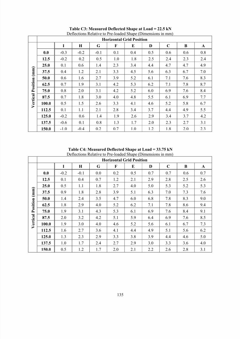
8/2/2019 Design of Bearing Stiffeners in Cold Formed C-Sections
http://slidepdf.com/reader/full/design-of-bearing-stiffeners-in-cold-formed-c-sections 149/151
135
Table C3: Measured Deflected Shape at Load = 22.5 kN
Deflections Relative to Pre-loaded Shape (Dimensions in mm)
Horizontal Grid Position
I H G F E D C B A
0.0 -0.3 -0.2 -0.1 0.1 0.4 0.5 0.6 0.6 0.8
12.5 -0.2 0.2 0.5 1.0 1.8 2.5 2.4 2.3 2.425.0 0.1 0.6 1.4 2.3 3.4 4.4 4.7 4.7 4.9
37.5 0.4 1.2 2.1 3.3 4.5 5.6 6.3 6.7 7.0
50.0 0.6 1.6 2.7 3.9 5.2 6.1 7.1 7.6 8.3
62.5 0.7 1.9 3.1 4.2 5.3 6.2 7.1 7.8 8.7
75.0 0.8 2.0 3.1 4.2 5.2 6.0 6.9 7.6 8.4
87.5 0.7 1.8 3.0 4.0 4.8 5.5 6.1 6.9 7.7
100.0 0.5 1.5 2.6 3.3 4.1 4.6 5.2 5.8 6.7
112.5 0.1 1.1 2.1 2.8 3.4 3.7 4.4 4.9 5.5
125.0 -0.2 0.6 1.4 1.9 2.6 2.9 3.4 3.7 4.2
137.5 -0.6 0.1 0.8 1.3 1.7 2.0 2.3 2.7 3.1
V e r t i c a l P o s i t i o n ( m m )
150.0 -1.0 -0.4 0.2 0.7 1.0 1.2 1.8 2.0 2.3
Table C4: Measured Deflected Shape at Load = 33.75 kN
Deflections Relative to Pre-loaded Shape (Dimensions in mm)
Horizontal Grid Position
I H G F E D C B A
0.0 -0.2 -0.1 0.0 0.2 0.5 0.7 0.7 0.6 0.7
12.5 0.1 0.4 0.7 1.2 2.1 2.9 2.8 2.5 2.6
25.0 0.5 1.1 1.8 2.7 4.0 5.0 5.3 5.2 5.3
37.5 0.9 1.8 2.8 3.9 5.1 6.3 7.0 7.3 7.6
50.0 1.4 2.4 3.5 4.7 6.0 6.8 7.8 8.3 9.0
62.5 1.8 2.9 4.0 5.2 6.2 7.1 7.8 8.6 9.4
75.0 1.9 3.1 4.3 5.3 6.1 6.9 7.6 8.4 9.1
87.5 2.0 3.2 4.2 5.1 5.9 6.4 6.9 7.6 8.5
100.0 1.9 3.0 4.0 4.6 5.2 5.6 6.1 6.7 7.3
112.5 1.6 2.7 3.6 4.1 4.4 4.9 5.1 5.6 6.2
125.0 1.3 2.3 2.9 3.3 3.8 3.9 4.4 4.6 5.0137.5 1.0 1.7 2.4 2.7 2.9 3.0 3.3 3.6 4.0
V e r t i c a l P o s i t i o n ( m m )
150.0 0.5 1.2 1.7 2.0 2.1 2.2 2.6 2.8 3.1
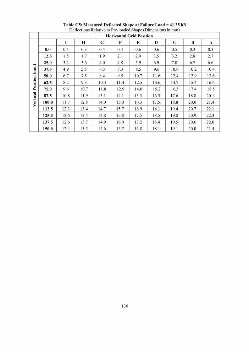
8/2/2019 Design of Bearing Stiffeners in Cold Formed C-Sections
http://slidepdf.com/reader/full/design-of-bearing-stiffeners-in-cold-formed-c-sections 150/151
136
Table C5: Measured Deflected Shape at Failure Load = 41.25 kN
Deflections Relative to Pre-loaded Shape (Dimensions in mm)
Horizontal Grid Position
I H G F E D C B A
0.0 0.4 0.3 0.4 0.4 0.6 0.6 0.5 0.3 0.3
12.5 1.5 1.7 1.9 2.1 2.9 3.5 3.2 2.8 2.7
25.0 3.2 3.6 4.0 4.8 5.9 6.9 7.0 6.7 6.6
37.5 4.9 5.5 6.3 7.3 8.5 9.6 10.0 10.2 10.4
50.0 6.7 7.5 8.4 9.5 10.7 11.6 12.4 12.9 13.6
62.5 8.2 9.3 10.3 11.4 12.5 13.6 14.7 15.4 16.6
75.0 9.6 10.7 11.8 12.9 14.0 15.2 16.3 17.4 18.5
87.5 10.8 11.9 13.1 14.1 15.3 16.5 17.6 18.8 20.1
100.0 11.7 12.8 14.0 15.0 16.3 17.5 18.8 20.0 21.4
112.5 12.3 13.4 14.7 15.7 16.9 18.1 19.4 20.7 22.1
125.0 12.6 13.4 14.8 15.8 17.5 18.5 19.8 20.9 22.3
137.5 12.6 13.7 14.9 16.0 17.2 18.4 19.5 20.6 22.0
V e r t i c a l P o s i t i o n ( m m )
150.0 12.4 13.5 14.6 15.7 16.8 18.1 19.1 20.0 21.4
8/2/2019 Design of Bearing Stiffeners in Cold Formed C-Sections
http://slidepdf.com/reader/full/design-of-bearing-stiffeners-in-cold-formed-c-sections 151/151
American Iron and Steel Institute
![Assessment of Cellular Beams with Transverse Stiffeners ...eprints.whiterose.ac.uk/85944/3/Paper_v5_GG_KDT.docx[1].pdf · Assessment of Cellular Beams with Transverse Stiffeners and](https://img.pdfslide.net/doc/110x75/5b33d3f97f8b9a6b548b717f/assessment-of-cellular-beams-with-transverse-stiffeners-1pdf-assessment.jpg)