Embed Size (px)
Citation preview

Design of
Blood-Lubricated Bearings Using Fluent
Presentation to the 2003 Fluent User Group Meeting
Cambridge Technology Development, Inc.CTDCTD
Edward Bullister, Ph.D.

Overview
Physics of Thin-Film Lubrication Governing Equations of the Lubrication Approximation Numerical Implementation in Nekton Fluent Example Problems
Steady Unsteady

Physics of Lubrication
Outflow < InflowCouette Flow Becomes Unbalanced when Plates are not Paralllel
U U

Approximation to N-S Equations Assumptions:
Laminar Flow, Re Small (no inertia) L/B - Large (reasonable; typically ~1000) No Slip Incompressible Case Presented Here

Lubrication Analogues
Physical Variable Computational Analogue
Pressure Temperature
Gap3/ Thermal Conductivity K
RHS Heat Source Q
Fluid Flux Heat Flux
Note:
μ

Implementation in Fluent
UDFs for: Material Properties Heat Source In Nonplanar Bearings,
Integration of Pressure x- and y- Components

Computational Work Comparison
Direct Solution Lubrication Approximation
Dimensions: 3 2
Equations: Full (Navier)-Stokes Energy

Force Predictions Comparison With Long–Bearing (L/D >> 1) Theory
L/D 1 10 100
Fluent Force Prediction (Newtons)
103 3860 42550
Exact Solution(Newtons)
Infinitely Long
428 4284 42840
Difference 76% 10% 0.6%
Conditions: No cavitation (continuous film) D = 40 mm; 3500 RPM; Gap = 2 mils; ε = 0.1; μ = 5 cp
Close Agreement where exact Solution is valid

Details of Journal Bearing at L/D = 1
Pressure (Pascal)

Cavitating Journal Bearing at L/D = 1
Pressure (Pascal)

Thrust Bearing
D = 40mm ω = 3500 RPM h = 1- 10 mils 4 Contoured Quadrants

Thrust Bearing – Steep Contours
Contours of Static Temperature (k)FLUENT 6.1 (2d, segregated, lam)
Apr 09, 2003
1.63e+06
1.55e+06
1.47e+06
1.39e+06
1.31e+06
1.22e+06
1.14e+06
1.06e+06
9.80e+05
8.98e+05
8.16e+05
7.35e+05
6.53e+05
5.71e+05
4.90e+05
4.08e+05
3.27e+05
2.45e+05
1.63e+05
8.16e+04
0.00e+00
Pressure Footprint Beneath Rotating Thrust Bearing (Plotted via its Temperature Analogue)
Computational Grid

Stiffened Thrust Bearing

Example: Unsteady Bearing
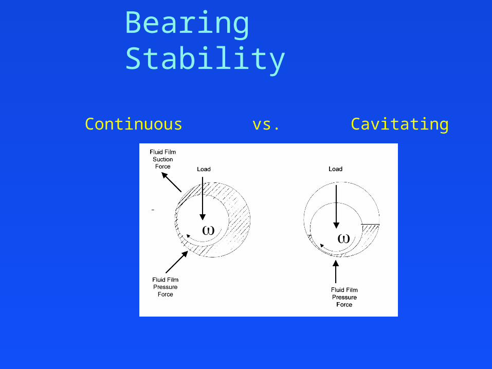
Bearing Stability
Continuous vs. Cavitating

Trajectories in Stable and Unstable Bearings

Stability Problem
Eigenvalue Analysis Predicts continuous film bearing neutrally stable:
= 0 + i /2
Simulations Use unsteady time stepping procedure Simulate with initial bearing eccentricity not at
equilibrium with steady applied load Track motion of piston in response to net forces

Unsteady Simulation Results
Bearing takes Circular Orbit around equilibrium position
Period of Orbit about ½ that of cylinder rotation consistent with:
• Eigenvalue Analysis
• Experimentally Observed “whirl” instability
Trajectory of Simulated Bearing

Recommendations
Design for sufficient load capacity to maintain allowable gaps at operating speeds
For continuous film bearings, avoid symmetry For unstable bearings, avoid symmetry

Design of Fluidic Devices Design Support and Analysis CFD Analysis
Brought to you by…
CTD @ attbi.com
781-790-1177


![Pressure Balanced Lubricated Plug Valves - API 6D Short ... · PDF fileSCV Pressure Balanced Lubricated Plug Valves - API 6D [Product Preview ] Pressure Balanced Lubricated Plug Valves](https://img.pdfslide.net/doc/110x75/5a9e06877f8b9a4a238da7ee/pressure-balanced-lubricated-plug-valves-api-6d-short-scv-pressure-balanced.jpg)