Embed Size (px)
Citation preview

Design of closed loop control for region 2 of a wind
turbine operated with CVT
1 Dept. of Electrical Engineering, Texas Tech University , Lubbock, TX 79409, US.2Dept. of Mechanical Engineering, University of North Carolina at Charlotte, NC 28223, USA.
3Dept. of Mechanical Engineering, Texas Tech University , Lubbock, TX 79409, US.
Santiago M. Novoa1, Nilabh Srivastava2, Luciano
Castillo3

Outline of the presentation
• Motivation for wind turbine speed control.
• Introduction to power electronics for grid integration of different
wind turbine topologies.
• The continuously variable transmission (CVT) as a feasible
solution.
• System Modeling. (Rotor – Drivetrain - Generator).
• CVT control (Open Loop – Development of closed loop control)
• Performance analysis of full modeled system (Simulations run with
10 minutes of wind data sampled at 50 Hz)

Motivation
Objectives
• Study findings can be used to develop a plan to reduce the
cost of wind energy, improve energy capture and mitigate
inverter reliability concerns.
• An economic feasibility study of CVT wind turbines
predicts that using a CVT would help reduce the cost
of energy by up to 11.2 % as compared with a DFIG
variable speed machine with PE [Cotrell, J. NREL].
Fundamental question
• Can we design a closed loop control system based on our
understanding of the dynamics of the CVT, that maximizes the
electric power generated by the wind turbine?

Regions of operation of variable speed wind
turbines
• In region 1, the wind speed is too low for the
turbine to generate power.
• Region 2 for each wind speed we need w such
that cp is MAX
• In region 3, the power output is limited by the
turbine; this occurs when the wind is sufficient
for the turbine to reach its rated output power.
• Region 4 is the period of stronger winds where
the power in the wind is so great that it could be
detrimental to the turbine, so the turbine shuts
down.

Control of Regions 2 and 3
We are particularly interested in studying the Region 2 control whose objective is to maximize wind energy
capture (Cp)
The power coefficient Cp (λ, β) is a function of the tip-speed ratio (TSR) λ and the blade pitch β. The turbine
operates at Cp Max at a certain pitch angle and TSR.
The pitch angle can be easily maintained at the optimal efficiency point, thus Region 2 control is primarily
concerned with varying the turbine speed to track the wind speed.
Region 3 control is typically performed via a separate pitch control loop.

Variable Speed operation
• Variable speed turbines can capture more power than fixed speed turbines operating in
the same wind conditions because they can track its maximum aerodynamic efficiency
point.
Methods for controlling a wind turbine system, By Andrew Rex and Katherine Johnson. August 2009
Power electronics in the feedback loop of a doubly
fed induction generator, in which the slip is
controlled.
Power electronics to rectify the variable speed
(variable frequency) AC produced by the
generator. And the invert it to match the grid
frequency.
CVT is an attractive alternative to power electronic
technologies

Wind turbine topologies in the market
Previous studies claim that using a CVT would reduce the cost of energy by up
to 11.2 % as compared to a DFIG variable speed machine.

Gearbox vs CVT
𝐼𝑟 * ω𝑟𝑜𝑡𝑜𝑟 = τ𝑤𝑖𝑛𝑑− τ𝑒𝑚
Where τ𝑒𝑚is a function exclusively of
generator currents (Ir and Is)
𝐼𝑟 * ω𝑟𝑜𝑡𝑜𝑟 = τ𝑤𝑖𝑛𝑑− τ𝑐𝑣𝑡,𝑝
𝐼𝑔 * ω𝑔𝑒𝑛 = τ𝑐𝑣𝑡,𝑠− τ𝑒𝑚
Control of CVT can be done
thru Fz1 and Fz2

Advantages of CVT
Allows the generator to operate at “fixed speed” while being driven by a
variable speed rotor. This brings
• A CVT can improve energy capture (wider speed range)
• A CVT can downsize pitch control
• A CVT can downsize switching electronics needed to ensure a constant grid frequency
of 60 Hz.

Active and reactive Power control

Real wind speed data
For our simulations instead of using a wind model typically involves specifying the
x-component hub-height wind speed we are using a sample of data recorded by
met towers at the Reese center just outside of Lubbock, Tx.
The recorded data was sampled at 50 Hz for 10 minutes.

Rotor Model
The Cp (λ,θ) curve is
approximated as follows as
proposed on ‘Power System
Modelling and Scripting’ By
Federico Milano
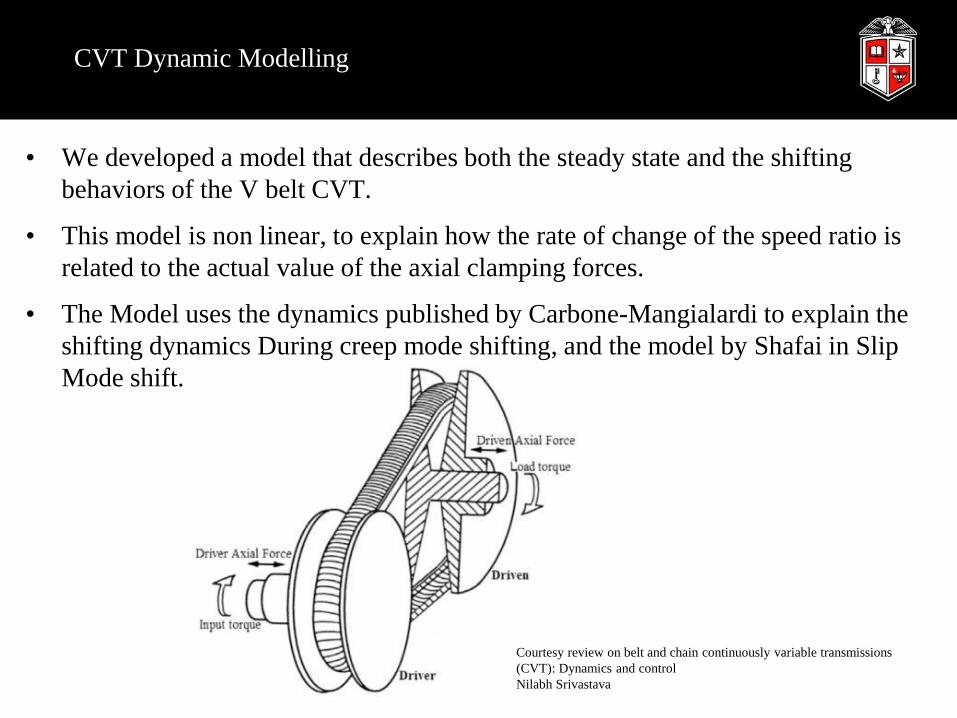
CVT Dynamic Modelling
• We developed a model that describes both the steady state and the shifting
behaviors of the V belt CVT.
• This model is non linear, to explain how the rate of change of the speed ratio is
related to the actual value of the axial clamping forces.
• The Model uses the dynamics published by Carbone-Mangialardi to explain the
shifting dynamics During creep mode shifting, and the model by Shafai in Slip
Mode shift.
Courtesy review on belt and chain continuously variable transmissions
(CVT): Dynamics and control
Nilabh Srivastava

Dynamic description of CVT behavior:
Similarly:
τf1 and τf2 are primary and secondary friction torques. The value they take during operation is not trivial and depends of other factors
(Belt-pulley contact normal force, belt running radius, direction of the relative velocity between the belt and pulley).
For example we use variables named ν1 and ν2 as slip indicators.
This EQ’s are important because they explain how the belt is related to the shifting gradients.

The CVT model recognizes two shifting regimes: 1) slow
shifting due to pulley bending, and 2) fast shifting due to
belt macroscopic slip.
We consider the system-level approach of Carbone to represent shifting under
creep or micro slip conditions.
Accordingly, the Shafai model is used to predict shifting dynamics under slip
conditions
Shifting models
The dimensionless parameter ADR as function of
the logarithms of the clamping forces
(Driver/Driven).
Courtesy of “Carbone, et al. 2005, "The influence
of pulley deformations on the shifting mechanism
of metal belt CVT.

Logarithm of the clamping force ratio as a function of the dimensionless torque load. Courtesy of:
“CVT Dynamics: Theory and experiments, by G.Carbone et al, in Mech. and Machine Theory, 42, 409, (2007)”
Logarithms of pulley thrust ratios versus speed ratios. Courtesy of “Vroemen, B. G.,
2001, Component control for the zero inertia powertrain”.

CVT Model

CVT, Rotor Side
• Tracking the wind maximum coefficient of performance requires maintaining the rotor blades at a
specific tip-speed ratio.
• This necessity of speed control makes controlling the wind turbine (WT) with a CVT a logical
choice, as load torques can be controlled through variation of the clamping forces on the primary
and secondary sides.

Control
• Typical wind turbine torque control is used but in the context of CVT actuation instead of the
usual generator torque.
Initial Conditions in all cases:
r1_init = 2.5 inches
r2_init = 5 inches
w1_init = 7*3.5/40;
w2_init = w1_init*(r1_init/r2_init)*1.2;
r1_max = 7 inches = r2_max
r1_min = 0.5 inches = r2_min

SLIDE REMOVED UNTIL OFFICIAL PUBLICATION OF
PAPER IN FALL 2015

SLIDE REMOVED UNTIL OFFICIAL PUBLICATION OF PAPER
IN FALL 2015
• The key objective of Region 2 is to track λopt while pitch is fixed.

SLIDE REMOVED UNTIL OFFICIAL PUBLICATION OF PAPER
IN FALL 2015