Embed Size (px)
Citation preview

International Research Journal of Engineering and Technology (IRJET) e-ISSN: 2395 -0056
Volume: 03 Issue: 03 | Mar-2016 www.irjet.net p-ISSN: 2395-0072
© 2016, IRJET | Impact Factor value: 4.45 | ISO 9001:2008 Certified Journal | Page 1407
Design Of Control System For Articulated Robot Using Leap Motion
Sensor
Mr. Rajesh D. Savatekar1, Mr. A.A.Dum 2
1 Student, Department of Electronics Technology Engg.,
Shivaji University, Kolhapur, Maharashtra, India [email protected]
2 Assistant Professor
Department of Electronics Technology Engg. Shivaji University, Kolhapur, Maharashtra, India
Email- [email protected]
---------------------------------------------------------------------***---------------------------------------------------------------------
Abstract - In this proposed System, The main aim of a making human hand tracking system, is to create interaction between human hand and robotic arm. Man–machine interaction gives the relation between human and computer. The idea shows the creation of a robotic arm which is as similar to the human arm as possible and not to limit the arm to one set of task. The arm is to be controlled using Leap motion[1] controller in X,Y and Z direction. Similarity of human hand with the robotic arm is the basic aim of the project but, there is an underlying aim which is to expand the functionality of the arm, once the basic model is created like as example spot-welding robot. At the same time when we use image processing technique, it is difficult to control, since it needs different identification schemes of hands such as pattern recognition, tracking, color identification and giving X and Y axis to the points. This drawback is removed by our system. We can Configure the Robot without Changing the Program, And also for multiple Operations but based on Application, which you want to use.
Key Words: Leap motion Sensor, Microcontroller,
Design Robotic Arm(Articulated Robot), Servo Motors, Programing Java and C++.
1.INTRODUCTION Nowadays, human-computer interaction is mainly based on the pointing or typewriter-style devices. This kind of interaction can limit the natural ways of manipulation using the hands, which may result in a complication of simple tasks. One of the overcomplicated control examples is rotating a three-dimensional object. Using a computer mouse, a user needs to grab the object and rotate it using the mouse, which can only operate in a two-dimensional space. The rotation operation represented by the mouse’s
movement is unintuitive for humans and users need a few attempts to understand how it works. In the real world, however, the rotation task is natural thus it is simple how to move hands to rotate the object in a desired way. The newest sensors provide data that can be
successfully used to recognize gestures and therefore
control a computer. Currently, there are several
devices that yield data useful for the gesture
recognition. An example of such a controller is
Microsoft Kinect . It provides a three-dimensional point
cloud of the observed scene, but was designed for
applications that interpret the movement of the whole
body of the user. That is why it lacks the needed
accuracy for hand gesture recognition.
Another device that is designed to track the movements of a hand and fingers is Leap Motion[1] Controller developed by Leap Motion, Inc. released in July 2013. The Leap Motion is a small device, which can be placed in front of a computer. It presents the opportunity for a new way of interacting with technology that is yet to be evaluated. The Leap Motion controller is a small device that can be connected to a computer using a USB. It can then sense hand movements in the air above it, and these movements are recognized and translated into actions for the computer to perform. The Leap Motion controller is said to be highly sensitive to very small movements, and is capable of mapping movements of the entire hand above it. The aim is produce efficient, affordable technology applications that can be easily accessed by the Industries of these workers. The Leap Motion

International Research Journal of Engineering and Technology (IRJET) e-ISSN: 2395 -0056
Volume: 03 Issue: 03 | Mar-2016 www.irjet.net p-ISSN: 2395-0072
© 2016, IRJET | Impact Factor value: 4.45 | ISO 9001:2008 Certified Journal | Page 1408
project has a high level aim of producing an application that can recognize hand movements.
Fig1: Diagram Of Proposed System
The main aim of making human hand tracking system is to create interaction between human hand and robotic arm. Man–machine interaction gives the relation between human and computer [2], [3]. The idea shows the creation of a robotic arm which is as similar to the human arm as possible and not to limit the arm to one set of task. Also, the arm is to be controlled using Leap motion controller in X,Y and Z direction. Similarity of human hand with the robotic arm is the basic aim of the project but, there is an underlying aim which is to expand the functionality of the arm once the basic model is created like as example spot-welding robot. The above fig1. Shows the proposed System ,We are using only one Leap motion Sensor for X,Y and Z axes motion, because it removes the drawback of Image processing technique and Improves the speed of work in real time, so we can place this system any where we want to place. Leap motion sensor is connected to PC through USB and PC is connected to Microcontroller. It gives the position of hand, fingers and palm. Hence, Captured Image frames from leap motion sensor are processed in PC using Java and it is given to Microcontroller and then this signals are send to Articulated Robot. This System introduce the technology used to track the Hand Arm and interface it to control the robotic arm for different activities. The motions can be controlled by the user by moving our hand in any direction. This proposed System is very important since it gives an intuitive way to develop human
centered forms of human machine interaction(HMI). At the same time when we use image processing technique, it is difficult to control, since it needs different identification schemes of hands such as pattern recognition, tracking, color identification and giving X and Y axis to the points [4]. This drawback is removed by our system. 2. LITETRATURE REVIEW
At present there is enormous amount of work is done in order to identify the motion of the hand. Lots of articles have been used in surveying the detection for the motion of hand. The different fields using this technique contain automatic hand language, automatic sketching, computer graphics and also industrial robots used to work instead of humans. This paper gives the most successful technique to use robotics. In these area two types of techniques[5], [6] are used: 1) contact type 2) non-contact type 1) Contact type: Contact type of devices contain data gloves, electromagnetic tracking system, exoskeleton etc. 2) Non-contact type: This type contains vision based system, speech recognition, camera based etc. Our technique comes under non-contact type since it uses a Leap motion sensor to track the hand and fingers. Unlike Microsoft Kinect, Leap Motion does not provide access to raw data in the form of a cloud of points. Captured data is processed by proprietary drivers supplied by vendor and accessible through API. Leap Motion was intended to be a human-computer interface, not general purpose3D scanner, so it is optimized for recognizing human hands and pointy objects. The main data container we get from Leap Motion API is a Frame. Average frame rate while using dual core laptop and USB 2.0 interface, is 50 frames per second. One frame consists of hands, fingers, pointables (objects directly visible by controller), and additional information, like gestures recognized by simple built-in recognition mechanism, frame timestamp, rotation, translation, and scaling data. For purposes of this project, we have created our own data format. It contains only in formation necessary for us and allows to easily save captured frames to file, and read them later for processing and testing purposes. An articulated robot is a robot with rotary joints. (e.g. a legged robot or an industrial robot). Articulated robots can range from simple two-jointed structures to systems with 10 or more interacting joints. They are powered by a variety of means, including electric
Serial to USB
Converter
Micro-
Controller

International Research Journal of Engineering and Technology (IRJET) e-ISSN: 2395 -0056
Volume: 03 Issue: 03 | Mar-2016 www.irjet.net p-ISSN: 2395-0072
© 2016, IRJET | Impact Factor value: 4.45 | ISO 9001:2008 Certified Journal | Page 1409
motors. Some types of robots, such as robotic arms, can be articulated or non-articulated.[7]
The Leap Motion works with two infrared (IR) cameras and three IR LEDs as a depth sensor in a limited field of view (FOV) (Figure2 ) of 8 cubic feet (approximately 61 cubic centimeters). Using the stereoscopy from both cameras, the device can minimize errors from tools, fingers and hand features and is built on a unique mathematical model to maximize speed and precision. As the device detects these features, it provides updates in frames of data. Each frame has a list of tracking data such as hands, fingers, tools, recognized gestures and factors describing the overall motion of the scene.
Figure 2. Leap Motion's Field Of View
This allows Leap Motion to recognize hand features such as hand palm orientation, fingers‟ length, width and orientation, hand opening and other non-hand features including tools and computer screen location. Furthermore, it incorporates in its Software Development Kit (SDK) the recognition of a few gestures including “circle gesture”, swipe and tap that are shown in its interface (Figure3 ). With respect to controllers like Nintendo Wii Remote and Microsoft Kinect, more focused on body and body members, Leap Motion provides a fine-grained hand control, which is clearly promising for building new DMIs.
Figure 3. Leap Motion SDK’s FOV and tracking features
Although it has a limited space to work with, the hand tracking is very precise. The Leap Motion SDK comes with three different presets of tracking: Robust mode, Low resource mode and Auto orientation device mode. Furthermore, it has also three different performance sets: High precision, High Speed and Balanced tracking. In the High Precision mode, the dataflow provides circa 50 data frames per second (data fps), representing about 20 milliseconds (ms) of delay in the computer music field. With the Balanced tracking its data fps increases by a factor of two, reducing the delay to 10 ms, combined with a still good precision. By choosing the High Speed mode, it loses a perceptible amount of precision with tracking but reduces the delay to 5 ms (approximately 200 fps).
Motion control is a sub-field of automation, in which the position or velocity of machines are controlled using some type of device such as a hydraulic pump, linear actuator, or electric motor, generally a servo. Motion control is an important part of robotics and CNC machine tools, however in these instances it is more complex than when used with specialized machines, where the kinematics are usually simpler. The latter is often called General Motion Control (GMC). Motion control is widely used in the packaging, printing, textile, semiconductor production, and assembly industries. But, these days, the focus of motion control is the special control technology of motion systems with electric actuators such as dc/ac servo motors. Control of robotic manipulators is also included in the field of motion control because most of robotic manipulators are driven by electrical servo motors and the key objective is the control of motion.[20]A motion controller to generate set points (the desired output or motion profile) and close a position or velocity feedback loop.[21]
Machine vision (MV) is the technology and methods used to provide imaging-based automatic inspection and analysis for such applications as automatic inspection, process control, and robot guidance in industry.[22]The scope of MV is broad.[23] MV is related to, though distinct from, computer vision.[24]Machine vision methods are defined as both the process of defining and creating an MV solution,[25] and as the technical process that occurs during the operation of the solution. Here the latter is addressed. As of 2006, there was little standardization in the interfacing and configurations used in MV. This includes user interfaces, interfaces for the integration

International Research Journal of Engineering and Technology (IRJET) e-ISSN: 2395 -0056
Volume: 03 Issue: 03 | Mar-2016 www.irjet.net p-ISSN: 2395-0072
© 2016, IRJET | Impact Factor value: 4.45 | ISO 9001:2008 Certified Journal | Page 1410
of multi-component systems and automated data interchange.[26] Nonetheless, the first step in the MV sequence of operation is acquisition of an image, typically using cameras, lenses, and lighting that has been designed to provide the differentiation required by subsequent processing.[27] MV software packages then employ various digital image processing techniques to extract the required information, and often make decisions (such as pass/fail) based on the extracted information.[28] A robotic arm is a robot manipulator, usually programmable, with similar functions to a human arm. The links of such a manipulator are connected by joints allowing either rotational motion (such as in an articulated robot) or translational (linear) displacement. The links of the manipulator can be considered to form a kinematic chain. The business end of the kinematic chain of the manipulator is called the end effectors and it is analogous to the human hand. The end effectors can be designed to perform any desired task such as welding, gripping, spinning etc., depending on the application. The robot arms can be autonomous or controlled manually and can be used to perform a variety of tasks with great accuracy. The robotic arm can be fixed or mobile (i.e. wheeled) and can be designed for industrial or home applications. Recognizing hand gestures for interaction can help in achieving the ease and naturalness desired for human computer interaction. Users generally use hand gestures for expression of their feelings and notifications of their thoughts. Researcher in his work reported that hand has been widely used in comparison to other body parts for gesturing as it is a natural form of medium for communication between human to human hence can best suited for human computer interaction. hand has been widely used in comparison to other body parts as medium for communication between human to human - Hand 21%, Fingers 10%, Head + Fingers 2%, foot 2%, Object + Finger 4%, Hand + Object 5%, Body 7%, Hand + Head 7%, Multiple hands 13% ,Others 9%. The values shows the different body parts or objects identified in the literature employed for gesturing.
3. THE CLASSIFICATION OF GESTURES
In another publication, Aigner et al. [8] presented classification, which are more tailored for hand gesture recognition purposes, drawing on concepts from Karam and schraefel work. They distinguished five categories of gestures:
3.1 Pointing
Used to point object or indicate direction. Formally,
it involve pointing to establish the identity or spatial location of an object within the context of the application domain [9].This applies not only to indicate by the index finger, but also by any finger or any number of fingers. It is also independent of finger orientation and curvature, while gesture has a indication meaning. Equivalent to deictic gesture in Karam and Schraefel literature.
3.2 Semaphoric
Group which consists of gesture posture and dynamics of gesture, which are used to convey specific meanings. Formally, semaphoric approaches may be referred to as “communicative” in that gestures serve as a universe of symbols to be communicated to the machine [10]. Due to the fact that semaphoric are symbolic gestures, their layout can be unrelated to their meaning. Distinguished three semaphoric gesture types of static, dynamic and strokes. The first one concerns specific hand posture, such as thumbs-up meaning approval symbol. Dynamic semaphorics convey their meaning through movement, for example waving of hand to greet somebody. The last one group are similar to dynamic semaphorics gesture, but this represents fast, stroke-like movements, such as swipe gesture.
3.3 Iconic
Used to demonstrate shape, size, curvature of object
or entities. In contrast to the semaphoric gestures, their layout or motion path is strictly related to their meaning. Iconic gestures can be divided into static and dynamic. The former group is performed by hand postures, such as rectangle formed by the thumb and forefingers of both hands. The latter group is often used to map edge line of objects by means of motion paths. For instance showing a simplified sine function characteristics with finger movements.
3.4 Pantomimic
Used to imitate per formation of specific task or activity without any tools or objects. Pantomimic gesture are characterized by a high variability of posture and movements. An example of this gesture type can be weapon reload or movement of a knife slicing bread.

International Research Journal of Engineering and Technology (IRJET) e-ISSN: 2395 -0056
Volume: 03 Issue: 03 | Mar-2016 www.irjet.net p-ISSN: 2395-0072
© 2016, IRJET | Impact Factor value: 4.45 | ISO 9001:2008 Certified Journal | Page 1411
Fig:4 Classification of Gestures
3.5 Manipulation
Used to control the position, rotation and scale of the object or entity in pace. Manipulation gestures constitute a direct interaction between the manipulated object and a hand or a tool that performs gesture. It follows, that the movement of the manipulated object must be strictly dependent on the motion gesture.
4. THEORY AND CONCEPT
4.1 Concept In this proposed System, The main aim of a
making human hand tracking system, is to create interaction between human hand and robotic arm. Man–machine interaction gives the relation between human and computer. The idea shows the creation of a robotic arm which is as similar to the human arm as possible and not to limit the arm to one set of task. The arm is to be controlled using Leap motion controller in X,Y and Z direction. Similarity of human hand with the robotic arm is the basic aim of the project but, there is an underlying aim which is to expand the functionality
of the arm once the basic model is created like as example spot-welding robot.
4.2 Proposed System In this system, we are using Leap motion sensor, because it analyzes the objects observed in the device’s field of view. It recognizes hands, fingers, and tools, reporting discrete positions, gestures, and motion. The controller’s field of view is an inverted pyramid centred on the device. The effective range of the controller extends from approximately 25 to 600 millimetres above the device (1 inch to 2 feet). The controller itself is accessed and programmed through Application Programming Interfaces (APIs), with support for a variety of programming languages, ranging from C, C++ to Python , JavaScript, Objective-C. Recently many robotic arm is used in industries which will work in accordance to the program, such as lifting the object, placing the object, drilling etc. but these robots are trained, any change in the working of robots will change the program, but with this idea we can function whatever we want to do without much change. So this drawback is removed by our project, we use Leap motion free space sensor for communicating with robotic Arm. Hence, due to this system we control the Robotic Arm without changing the Program or Giving training. We can Configure the Robot without Changing the Program, And also for multiple Operations but based on Application, which you want to use. Conventional methods for detecting human arm movements make use of mechanical sensors, such as accelerometer, proximity sensors, which increases the cost and it is dedicated to one person only but this proposed system uses Touch less Leap Motion sensor are used. Any human can arm movements can be replicated, there are no restrictions too. Due to the use of high signal processing, this system establishes synchronization between human arm movements and robotic arm movements. The Leap Motion Controller uses infrared (IR) imaging to determine the position of predefined objects in a limited space in real time. Technically, very few details are known about the precise nature of the algorithms used due to patent and trade secret restrictions. However, from inspection of the controller, it is clear that three separate IR LED emitters are used in conjunction with two IR cameras. Therefore, the controller can be categorized as an optical tracking system based on the stereo vision principle. According to the official information [11], the Leap software analyzes the objects observed in the
International Research Journal of Engineering and Technology (IRJET) e-ISSN: 2395 -0056
Volume: 03 Issue: 03 | Mar-2016 www.irjet.net p-ISSN: 2395-0072
© 2016, IRJET | Impact Factor value: 4.45 | ISO 9001:2008 Certified Journal | Page 1412
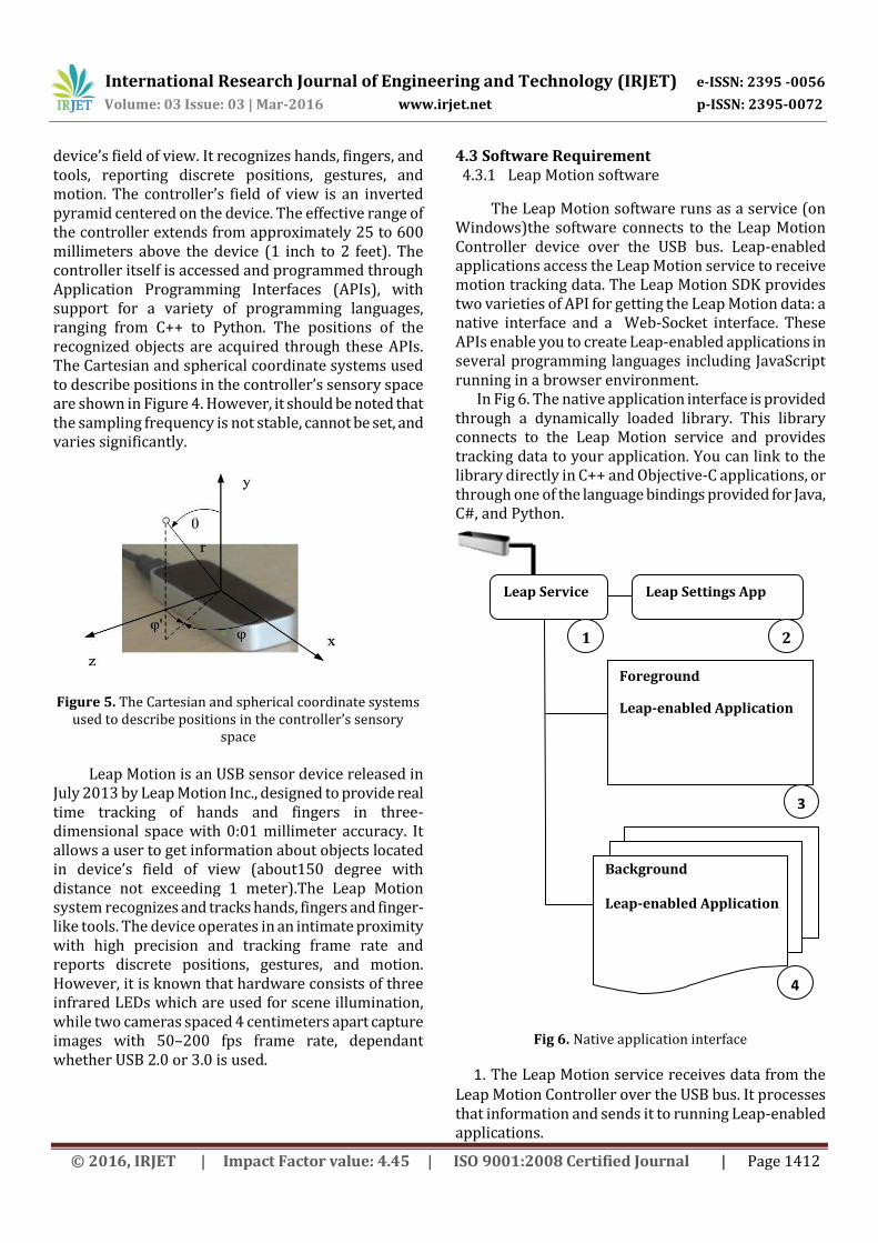
device’s field of view. It recognizes hands, fingers, and tools, reporting discrete positions, gestures, and motion. The controller’s field of view is an inverted pyramid centered on the device. The effective range of the controller extends from approximately 25 to 600 millimeters above the device (1 inch to 2 feet). The controller itself is accessed and programmed through Application Programming Interfaces (APIs), with support for a variety of programming languages, ranging from C++ to Python. The positions of the recognized objects are acquired through these APIs. The Cartesian and spherical coordinate systems used to describe positions in the controller’s sensory space are shown in Figure 4. However, it should be noted that the sampling frequency is not stable, cannot be set, and varies significantly.
Figure 5. The Cartesian and spherical coordinate systems
used to describe positions in the controller’s sensory space
Leap Motion is an USB sensor device released in July 2013 by Leap Motion Inc., designed to provide real time tracking of hands and fingers in three-dimensional space with 0:01 millimeter accuracy. It allows a user to get information about objects located in device’s field of view (about150 degree with distance not exceeding 1 meter).The Leap Motion system recognizes and tracks hands, fingers and finger-like tools. The device operates in an intimate proximity with high precision and tracking frame rate and reports discrete positions, gestures, and motion. However, it is known that hardware consists of three infrared LEDs which are used for scene illumination, while two cameras spaced 4 centimeters apart capture images with 50–200 fps frame rate, dependant whether USB 2.0 or 3.0 is used.
4.3 Software Requirement 4.3.1 Leap Motion software
The Leap Motion software runs as a service (on Windows)the software connects to the Leap Motion Controller device over the USB bus. Leap-enabled applications access the Leap Motion service to receive motion tracking data. The Leap Motion SDK provides two varieties of API for getting the Leap Motion data: a native interface and a Web-Socket interface. These APIs enable you to create Leap-enabled applications in several programming languages including JavaScript running in a browser environment. In Fig 6. The native application interface is provided through a dynamically loaded library. This library connects to the Leap Motion service and provides tracking data to your application. You can link to the library directly in C++ and Objective-C applications, or through one of the language bindings provided for Java, C#, and Python.
Fig 6. Native application interface
1. The Leap Motion service receives data from the Leap Motion Controller over the USB bus. It processes that information and sends it to running Leap-enabled applications.
Leap Service Leap Settings App
Foreground
Leap-enabled Application
Background
Leap-enabled Application
1 2
3
4

International Research Journal of Engineering and Technology (IRJET) e-ISSN: 2395 -0056
Volume: 03 Issue: 03 | Mar-2016 www.irjet.net p-ISSN: 2395-0072
© 2016, IRJET | Impact Factor value: 4.45 | ISO 9001:2008 Certified Journal | Page 1413
By default, the service only sends tracking data to the foreground application. However, applications can request that they receive data in the background. 2.The Leap Motion application runs separately from the service and allows the computer user to configure their Leap Motion installation 3. The foreground Leap-enabled application receives motion tracking data from the service. A Leap-enabled application can connect to the Leap Motion service using the Leap Motion native library. Application can link against the Leap Motion native library either directly (C++ and Objective-C) or through one of the available language wrapper libraries (Java, C#, and Python). 4.3.2 Processing Software
Processing is a simple programming environment that was created to make it easier to develop visually oriented applications with an emphasis on animation and providing users with instant feedback through interaction. The developers wanted a means to “sketch” ideas in code. As its capabilities have expanded over the past decade, Processing has come to be used for more advanced production-level work in addition to its sketching role. Originally built as a domain-specific extension to Java targeted towards artists and designers, Processing has evolved into a full-blown design and prototyping tool used for large-scale installation work, motion graphics, and complex data visualization. Processing is based on Java, but because program elements in Processing are fairly simple, you can learn to use it even if you don't know any Java. If you're familiar with Java, it's best to forget that Processing has anything to do with Java for a while, until you get the hang of how the API works. An important goal for the project was to make this type of programming accessible to a wider audience. For this reason, Processing is free to download, free to use, and open source. But projects developed using the Processing environment and core libraries can be used for any purpose. This model is identical to GCC, the GNU Compiler Collection. GCC and its associated libraries (e.g. lib c) are open source under the GNU Public License (GPL), which stipulates that changes to the code must be made available. However, programs created with GCC (examples too numerous to mention) are not themselves required to be open source.
Processing consists of:
The Processing Development Environment (PDE). This is the software that runs when you double-click the Processing icon. The PDE is an Integrated Development Environment (IDE) with a minimalist set of features designed as a simple introduction to programming or for testing one-off ideas.
A collection of functions (also referred to as commands or methods) that make up the “core” programming interface, or API, as well as several libraries that support more advanced features such as sending data over a network, reading live images from a webcam, and saving complex imagery in PDF format.
A language syntax, identical to Java but with a few modifications.
The Processing approach has also been applied to electronics through the Arduino and Wiring projects. Arduino uses a syntax inspired by that used with Processing, and continues to use a modified version of the Processing programming environment to make it easier for students to learn how to program robots and countless other electronics projects. The primary charge of the Foundation is to develop and distribute the Processing software. This includes the original Processing (Java), p5.js (Java-script), and Processing.py (Python). 4.3.3 The Interaction Box
The size of the Interaction Box is determined by the Leap Motion field of view and the user’s interaction height setting (in the Leap Motion control panel). The controller software adjusts the size of the box based on the height to keep the bottom corners within the filed of view. If you set the interaction height higher, then the box becomes larger. Users can set the interaction height based on the height they prefer to hold their hands when using the controller. Some users like to hold their hands much higher above the device than others. By using the Interaction Box to map the Leap Motion coordinate system to your application coordinate system, you can accommodate both types of user. A user can also set the interaction height to adjust automatically. If the user moves his or her hands below the current floor of the interaction box, the controller software lowers the height (until it reaches the minimum height); likewise if the user moves above the interaction box, the controller raises the box.

International Research Journal of Engineering and Technology (IRJET) e-ISSN: 2395 -0056
Volume: 03 Issue: 03 | Mar-2016 www.irjet.net p-ISSN: 2395-0072
© 2016, IRJET | Impact Factor value: 4.45 | ISO 9001:2008 Certified Journal | Page 1414
Fig:7 Interaction Box
4.3.4 Tracking Model:
The Leap Motion API defines a class representing each of the primary tracked objects
5. SYSTEM IMPLIMENTATION
In the fig:8 shows the Proposed system of articulated Robot. It is made up of Acrylic sheet. It’s part is Designed in Auto-CAD. Its design is given below.
Fig: 8 Implemented Robotic arm
5.1.1 Industrial Robot An industrial robot is a programmable, multi-functional manipulator designed to move materials, parts, tools, or special devices through variable programmed motions for the performance of a variety of tasks.
Interaction Box, depth(147mm) Y=317.5mm Interaction Box, Hight(235mm) Y=82.5mm Interaction Box, Center(0,200,0) Interaction Box, Width(235mm) Y=317.5mm Interaction Box, Hight(235mm) Y=82.5mm Interaction Box, Center(0,200,0)
Z=73.5mm Z=73.5mm
X=117.5mm X=117.5mm

International Research Journal of Engineering and Technology (IRJET) e-ISSN: 2395 -0056
Volume: 03 Issue: 03 | Mar-2016 www.irjet.net p-ISSN: 2395-0072
© 2016, IRJET | Impact Factor value: 4.45 | ISO 9001:2008 Certified Journal | Page 1415
5.1.2 Robot Construction
The manipulator of an industrial robot consists of a number of rigid links connected by joints of different types, controlled and monitored by a computer.
The link assembly is connected to the body, which is usually mounted on a base.
To a large extend, the physical construction of a robot resembles a human arm.
A wrist is attached to the arm. To facilitate gripping or handling, a hand is
attached at the end of the wrist, this hand is called an end-effector.
The complete motion of the end- effector is accomplished through a series of motions and positions of the links, joints, and wrist.
Robot construction is concerned with the types and sizes of joints, links and other aspects of the manipulator.
5.1.3 Joints and Links of Robots
• A joint of an industrial robot is similar to a joint in the human body: It provides relative motion between two parts of the body.
• Each joint, or axis as it is sometimes called, provides the robot with a so-called degree-of-freedom (D.O.F) of motion.
• In nearly all cases, only one degree-of-freedom is associated with a joint.
• Connected to each joint are two links, an input link and output link.
• Links are the rigid components of the robot manipulator.
• The purpose of the joint is to provide controlled relative movement between the input link and the output link.
Fig 9:Joints and Links of Robot
• Most of robots are mounted on a stationary base on the floor.
• The base and its connection to the first joint is Link 0.
• Link 0 is the input link of joint 1, the first joint of a series of joints used in the construction of the robot.
• The output link of joint 1 is the link 1. • Link 1 is the input link to joint 2, whose output
link is link 2, and so forth
5.1.4 PROPOSED METHODOLOGY
In our proposed system leap motion captures the frames 200fps frame rate and according to command using C++ or java scripting , we get coordinates of hand, fingers and palm angles. It gives 150° of freedom and 8 cubic feet length from sensor to move our hand.
Fig 10:Prposed Methodology
Then, this received data from the leap motion sensor send to the Microcontroller to control the articulated robot. Shown in fig-11. Depending on the axis location the angle can be trace by the leap motion to give signal to robotic arm. For the movement of the robotic arm the angle signal is transmitted from PC to the micro controller and process the signal. The processed signal is the transmitted to the robotic arm to perform various actions.

International Research Journal of Engineering and Technology (IRJET) e-ISSN: 2395 -0056
Volume: 03 Issue: 03 | Mar-2016 www.irjet.net p-ISSN: 2395-0072
© 2016, IRJET | Impact Factor value: 4.45 | ISO 9001:2008 Certified Journal | Page 1416
Leap
Motion Controller Plug in to PC
Serial
Communication
PWM Signal
Fig:11: Proposed System
In this above proposed System, Articulated Robot is Made up of Acrylic Sheet and some screws using Standard Servo Motors with different Torques. Base motor has 13Kg Torque, Shoulder Motor has 11Kg and Elbow Motor has 3.2Kg Torque respectively. So, This all servo motors worked on PWM signal and This PWM Signal is Provided by microcontroller Amega-328P,it Provides 6-PWM output pins. Controller Programming is based on C/C++ using Arduino-IDE. To send data of Human hand gestures we use Leap Motion[1] Sensor. The Leap Motion[1] Sensor designed to provide real time tracking of hands and fingers in three-dimensional space with 0:01 millimetre accuracy. It allows a user to get information about objects located in device’s field of view (about150 degree with distance not exceeding 1 meter).The Leap Motion system recognizes and tracks hands, fingers and finger-like tools. The device operates in an intimate proximity
with high precision and tracking frame rate and reports discrete positions, gestures, and motion. However, it is known that hardware consists of three infrared LEDs which are used for scene illumination, while two cameras spaced 4 centimetres apart capture images with 50–200 fps frame rate, dependant whether USB 2.0 or 3.0 is used. Then, the Processing-IDE used for java programming, this IDE used for to communicate with sensor. Import the all library files of sensor and write code for collecting data from sensor using Java programming language. Then this all data mapped in the format of 0-180° using java programming and then transmit through serial communication to micro-controller board to control servo motor. Hence, we connect human to machine(Robot) using this proposed system.
6. RESULTS
Fig:12:Without Grab Motion.
Fig 13:With Grab Motion

International Research Journal of Engineering and Technology (IRJET) e-ISSN: 2395 -0056
Volume: 03 Issue: 03 | Mar-2016 www.irjet.net p-ISSN: 2395-0072
© 2016, IRJET | Impact Factor value: 4.45 | ISO 9001:2008 Certified Journal | Page 1417
7. CONCLUSIONS
This Proposed System describes Controlling a articulated Robotic Arm using Leap Motion Sensor. It helps me to gain a deeper understanding of robots and the whole field of computer science. In this Proposed work, we get Proper (Gestures) Hand Motion Result ,Using Leap Motion Sensor in Real-time. We Observed that, our system is worked successfully and In Real-time, We get X,Y and Z hand motions data using Leap Motion sensor by using Java Programming and this data mapped with Angle and send with serial communication to Arduino Uno Platform(AT328PU). The new improvement in algorithm is necessary for small precision movement in the Robotics System
8. REFERENCES [1] Leap motion https://developer.leapmotion.com/
[2] Mrs. Belagali P P, “An interactive robot control using image processing method”, IOSR journal of electronics & communication engineering(IOSR-JECE), ISSN: 22782834.ISBN: 2278-8735, PP :31-35.
[3] Markossigalas, HarisBaitzakis and panostrahanias,”Foundation of research and technology” Hellas (FOURTH)
[4] Yoshishigesato, “study of intelligent control of an arm robot equipped with ac-mos camera using a new type of image processing”, tsuruoka national college of technology, Yamagata prefecture, PP: 997-8511.
[5] Euijungjung, Jachoon lee, Byungjuyi, Member ,IEEE, Jooyoung Park, Shin‟ichiyuta, fellow,IEEE, and Si tac nah, ”IEEE/ASME transactionon mechatronics , “Development of a laser range finder based human tracking and control algorithm for a marathoner service robot”, PP: 1083-4435 vol 19. No.6, December 2013
[6] Guanglong Du, Ping Zhang, and Di li, “human manipulator interface based on multisensory process via kalman filters”, IEEE transaction on industrial electronics, PP: 0278-0046 vol.61,no.10, October 2013.
[7] http://ieeexplore.ieee.org/stamp/stamp.jsp?tp=&arnumber=548386
[8] HrvojeBenko Michael Haller David Lindbauer Alexandra Ion Shengdong Zhao Roland Aigner, Daniel Wigdor and Jeffrey Tzu Kwan ValinoKoh. Understanding mid-air hand gestures: A study of human preferences in usage of gesture types for hci. Technical report, November 2012.
[9] Yun Liu, Zhijie Gan, and Yu Sun. Static hand gesture recognition and its application based on support vector machines. In Software Engineering, Artificial Intelligence, Networking, and Parallel/Distributed Computing, 2008. SNPD ’08. Ninth ACIS International Conference on, pages 517–521, 2008
[10] Francis Quek, David McNeill, Robert Bryll, Susan Duncan, Xin-Feng Ma, CemilKirbas, Karl E. McCullough,
and Rashid Ansari. Multimodal human discourse: Gesture and speech. ACM Trans. Comput.-Hum. Interact., 9(3):171–193, September 2002.
BIOGRAPHIES
Mr. Rajesh D. Savatekar1 M.Tech-Embedded Systems Dept. Of Tech., Shivaji University, Kolhapur. [email protected]
Mr. A. A. Dum2 Assistant Professor Department of Technology, Shivaji University, Kolhapur. Email- [email protected]


![Leap motion [Шаповалов В.О.]](https://img.pdfslide.net/doc/110x75/558b3c24d8b42a29058b45cc/leap-motion--558c2483ed9bd.jpg)


![[Pause Café] Leap Motion](https://img.pdfslide.net/doc/110x75/558c81d2d8b42adf268b4692/pause-cafe-leap-motion.jpg)