Embed Size (px)
Citation preview

SCI PUBLICATION P281
Design of Curved Steel
Charles King BSc MSc DIC MIStructE
David Brown BEng CEng MICE
Published by: The Steel Construction Institute Silwood Park Ascot Berkshire SL5 7QN Tel: 01344 623345 Fax: 01344 622944

ii
2001 The Steel Construction Institute
Apart from any fair dealing for the purposes of research or private study or criticism or review, as permitted under the Copyright Designs and Patents Act, 1988, this publication may not be reproduced, stored or transmitted, in any form or by any means, without the prior permission in writing of the publishers, or in the case of reprographic reproduction only in accordance with the terms of the licences issued by the UK Copyright Licensing Agency, or in accordance with the terms of licences issued by the appropriate Reproduction Rights Organisation outside the UK.
Enquiries concerning reproduction outside the terms stated here should be sent to the publishers, The Steel Construction Institute, at the address given on the title page.
Although care has been taken to ensure, to the best of our knowledge, that all data and information contained herein are accurate to the extent that they relate to either matters of fact or accepted practice or matters of opinion at the time of publication, The Steel Construction Institute, the authors and the reviewers assume no responsibility for any errors in or misinterpretations of such data and/or information or any loss or damage arising from or related to their use.
Publications supplied to the Members of the Institute at a discount are not for resale by them.
Publication Number: SCI P281
ISBN 1 85942 126 1
British Library Cataloguing-in-Publication Data. A catalogue record for this book is available from the British Library.

iii
FOREWORD
The principal authors of this guide were Charles King and David Brown of The Steel Construction Institute. Thomas Cosgrove and Nina Knudsen, both of the Institute, developed the worked examples.
A steering group, whose advice, input and comment are very gratefully acknowledged, supported the preparation of the publication. The steering group comprised:
Mike Banfi Arup Research and Development David Hamilton Anthony Hunt Associates Limited Tim McCarthy UMIST Abdul Malik The Steel Construction Institute Bill Gover The Angle Ring Company Ltd Russ Barnshaw Barnshaws Steel Bending Group Mark Jordan Barnshaws Steel Bending Group
The guide has been sponsored by The Angle Ring Company and Barnshaws Steel Bending Group with support from the European Regional Development Fund.
v
CONTENTS Page No.
SUMMARY vii
1 INTRODUCTION 1
2 USE OF CURVED STEEL IN CONSTRUCTION 2 2.1 History 2 2.2 Curved steel in construction 6
3 CURVING PROCESS 7 3.1 Introduction 7 3.2 Roller bending 7 3.3 Induction bending 8 3.4 Combined induction/roller bending 9 3.5 Bending radii 10 3.6 Multi-radius curvature and three-dimensional curvature 10
4 METALLURGICAL ISSUES 11 4.1 Stress-strain relationship 12
5 GENERAL DESIGN ISSUES 14 5.1 Introduction 14 5.2 Locked-in stresses (or residual stresses) 14 5.3 Out-of-plane bending of flanges due to curvature 16 5.4 Frame analysis – elastic or plastic? 20 5.5 Modelling curved members for analysis 21 5.6 Allowing for the differences between the analysis model
and the actual structure 23 5.7 Buckling checks in software 25
6 MEMBERS CURVED IN ELEVATION 26 6.1 General 26 6.2 Arches 26 6.3 Design yield strength 32 6.4 Axial compression 33 6.5 Bending 36 6.6 Combined axial load and bending 39
7 PORTALS WITH CURVED RAFTERS 40 7.1 General 40 7.2 Portal frame analysis 40 7.3 Design using plastic analysis 40
8 MEMBERS CURVED ON PLAN 43 8.1 Behaviour of members curved on plan 43 8.2 Choice of section type 43 8.3 Differences between analysis and reality 43 8.4 Serviceability limit state 44 8.5 Calculation of warping stress effects 44 8.6 Classification 49 8.7 Hollow section resistance checks 49 8.8 I section resistance checks 51
vi
9 WORKED EXAMPLES 53 Curved roof beam 54 Three-pin arch 64 Two-pin lattice arch 75 Portal frame 81 Ellipse 88 Curved balcony member 95
10 REFERENCES 106
APPENDIX A Lateral torsional buckling of curved beams 107
APPENDIX B Specialist contact details 111
APPENDIX C Photographic credits 112

vii
SUMMARY
This publication covers the design of common types of curved steel members used in building structures. The publication demonstrates how to take account of the curvature so that member checks can be made in accordance with BS 5950–1:2000 or suitable modifications of that Standard.
The curving process is described, together with the effect that this has on the material properties. Guidance is offered on when the changes in material properties are small enough to be neglected, and additional checks are described where necessary.
Where the behaviour of curved members differs from that of straight members, this is described in the publication. Where necessary, modified resistance checks are prescribed for curved members, together with straightforward methods to take account of additional effects, such as transverse bending stresses.
The design of steel members curved in elevation, such as arches, and portal frames with curved rafters, is described, with guidance on the choice of effective lengths, modelling for computer analysis and simple approaches to determine approximate maximum forces and moments for initial sizing of members.
Members curved on plan experience torsion in addition to bending effects. The publication provides two methods to design such members, allowing for the torsional effects by either a simplified approach or by using a detailed analysis model of the member. The design of both open (I and H) and hollow sections is covered.
The publication includes six worked examples demonstrating the design of curved steel members used in different applications, curved in elevation, and curved on plan.
Dimensionnement de profils courbes en acier
Résumé
Cette publication couvre le dimensionnement des types classiques de profils courbes utilisés dans les structures de bâtiments. Elle montre comment on peut prendre en compte la courbure dans la vérification des éléments de structure de manière à respecter la norme BS 5950-1:2000 ou propose quelques modifications à ce règlement.
La procédure de cintrage est décrite ainsi que ses effets sur les propriétés du matériau. La publication donne les limites pour lesquelles les modifications des propriétés des matériaux sont petites et peuvent être négligées ainsi que les vérifications additionnelles lorsque cela est nécessaire.
Les différences de comportement entre éléments courbes et éléments droits sont analysées et, lorsque cela est nécessaire, des vérifications particulières de la résistance sont prescrites pour les éléments courbes. Des méthodes simples telles que celle des contraintes transversales de flexion, sont également données.
Le dimensionnement d'éléments en acier courbés en élévation, tels que les arcs et les portiques à membrure courbe, est décrit avec des indications concernant le choix des longueurs effectives, la modélisation pour analyse numérique. Des approches simples permettent aussi de déterminer les efforts maxima et les moments afin de simplifier le prédimensionnement.
viii
Les éléments courbes en plan présentent de la torsion en plus des effets de flexion. La publication donne deux méthodes de dimensionnement qui tiennent compte des effets de torsion, de manière approchée, d'une part, et pour une analyse détaillée, d'autre part. Les méthodes couvrent les profils ouverts (I et H) ainsi que les profils creux.
Six exemples illustrent le dimensionnement des éléments courbes tant en plan qu'en élévation.
Berechnung von gebogenen Stahlbauteilen
Zusammenfassung
Diese Publikation beschäftigt sich mit der Berechnung gewöhnlicher, gebogener Stahlbauteile, die in Tragwerken von Gebäuden verwendet werden. Die Publikation zeigt auf, wie die Biegung berücksichtigt wird, um Bauteilnachweise in Übereinstimmung mit BS 5950-1:2000 oder passenden Änderungen dieser Vorschrift zu führen.
Der Prozeß der Biegung wird beschrieben, zusammen mit dessen Auswirkungen auf die Materialeigenschaften. Eine Anleitung wird angeboten für den Fall, daß die Änderungen der Materialeigenschaften klein sind und vernachlässigt werden können, und zusätzliche Nachweise werden beschrieben, wo sie notwendig sind.
Dort, wo sich das Verhalten gebogener Bauteile von dem gerader Bauteile unterscheidet, wird es in der Publikation beschrieben. Wo nötig, werden veränderte Nachweise der Tragfähigkeit für gebogene Bauteile vorgeschrieben, zusammen mit den einfachen Nachweisen, um zusätzliche Effekte wie Querspannungen zu berücksichtigen.
Die Berechnung von in der Ansicht gebogenen Stahlbauteilen, wie Bogen und Rahmen mit gebogenen Riegeln, wird beschrieben, mit Anleitung zur Wahl der Knicklänge, der Modellierung für eine Computerberechnung und einfacher Lösungen zur Bestimmung der maximalen Kräfte und Momente für eine erste Dimensionierung der Bauteile.
Im Grundriss gebogene Bauteile erhalten zusätzlich zu Biegeeffekten noch Torsion. Diese Publikation stellt zur Berücksichtigung der Torsionseffekte zwei Methoden bereit, entweder eine einfache Näherungslösung oder ein genaues Berechnungsmodell. Die Berechnung sowohl offener (I und H) als auch geschlossener Querschnitte wird behandelt.
Die Publikation beinhaltet sechs Berechnungsbeispiele und führt die Berechnung von sowohl in der Ansicht als auch im Grundriss gebogenen Stahlbauteile vor.

ix
Progettazione di elementi curvi in acciaio
Sommario
In questa pubblicazione si affronta la progettazione dei tipi più comuni di elementi curvi in acciaio usati nelle strutture degli edifici. La pubblicazione mostra come tenere in conto la curvatura in modo che le verifiche dell’elemento siano condotte in accordo alle norme BS 5950-1:2000 o in base a sue opportune modifiche.
Viene descritto il processo di curvatura, unitamente al suo effetto sulle proprietà del materiale. E’ proposta una guida per valutare se le alterazione nelle proprietà dei materiali risultano piccole da essere trascurate oppure se sono necessarie verifiche addizionali (proposte nella pubblicazione).
La pubblicazione descrive quando il comportamento degli elementi curvi differisce da quello degli elementi ad asse rettilineo. Nel caso in cui sia necessario, sono prescritte, assieme a quelle degli elementi ad asse rettilineo, verifiche di resistenza modificate per gli elementi curvi, per tenere in conto effetti addizionali, come le sollecitazioni flessionali trasversali.
Viene affrontata la progettazione di elementi curvi in elevazione, come archi e strutture a telaio con traverso curvo, e sono fornite indicazioni sulla scelta della lunghezza libera di inflessione, sulla modellazione per l’analisi automatica e sugli approcci semplificati per determinare in modo approssimato le massime forze e momenti da utilizzare nella fase di dimensionamento iniziale.
La curvatura dell’elemento nel piano orizzontale aggiunge effetti torsionali a quelli flessionali. La pubblicazione propone due metodi per la progettazione di questi elementi, tenendo in conto gli effetti torsionali mediante un approccio semplificato o utilizzando un raffinato modello di analisi dell’elemento. Viene trattata la progettazione sia di profili aperti (sezione a I e a H) sia di profili scatolari chiusi.
Questa pubblicazione include sei esempi applicativi, finalizzati all’uso di approcci progettuali per elementi curvi per differenti applicazioni, considerando la curvatura sia nel piano verticale sia in quello orizzontale.
Proyecto de acero curvado
Resumen
Esta publicación cubre el proyecto de tipos comunes de piezas curvadas de acero usadas en edificios. Se muestra como tener en cuenta la curvatura de modo que las comprobaciones puedan hacerse en la BS 5950–1:2000 ó modificaciones adecuadas de esa norma.
Se describe el proceso de incurvado, así como el efecto que tiene sobre las propiedades del material. Se dan orientaciones sobre cuando es posible despreciar los cambios en aquéllos así como comprobaciones adicionales en su caso.
Por la publicación se describen las diferencias de comportamiento entre las barras curvas y las rectas y donde se estima adecuado, se incluyen las modificaciones necesarias en las comprobaciones de resistencia para piezas curvas junto con métodos rápidos para tener en cuenta efectos adicionales como las tensiones de flexión transversales.
Se describe el proyecto de piezas de acero curvas en alzado tales como arcos y pórticos en dinteles curvos con consejos sobre la elección de longitudes efectivas, modelado para

x
cálculo con ordenador y métodos simplificados para determinar esfuerzos máximos que permitan el dimensionamiento inicial de las piezas.
Las barras curvas en planta sufren esfuerzos torsión, además de los de flexión. La publicación da dos métodos para proyectar tales piezas permitiendo la consideración de las torsiones bien mediante un método simplificado, bien mediante un estudio detallado de la pieza. Se contempla el estudio tanto de perfiles abiertos (I y H) como de secciones cerradas.
La publicación incluye 6 ejemplos desarrollados que muestran el proyecto de las piezas curvas de acero usadas en diferentes aplicaciones con curvatura tanto en planta como en alzado.

SCI-P281 Design of Curved Steel
1
1 INTRODUCTION
Although curved iron and steel structures have been in existence since the mid 19th Century, to date there has been little guidance covering the design of curved steel elements.
When forces and moments are applied to a curved steel member, a number of effects not present with straight members need to be considered. Different effects must be considered if the member is curved in elevation, or curved in plan.
The guidance in this publication has been developed to assist structural engineers in the design of curved steel members. The guidance covers the design of I sections (beams and columns) and structural hollow sections in building construction. The advice presented is to account for the effects of curvature in such a way that the design rules in BS 5950–1:2000[1] (with suitable modifications where necessary) can be used.
The publication includes a series of worked examples covering common applications and structural arrangements in buildings. In the examples, I sections are considered to be acting with the web vertical. The principles outlined in the text allow designers to adapt the guidance to suit other arrangements.
The publication covers the design of members with significant curvature. It is not intended that the recommendations apply to the very minor curvature arising from precambering. Particular care is required when designing very shallow arches, and advice is offered in Section 6.
The physical process of producing a curved member is generally known as “bending”, and is so described in Sections 2 and 3. To avoid confusion with the ordinary engineering design concepts of bending (for example “bending” moments), the later Sections refer to the steel as “curved” and the process as “curving”.

SCI-P281 Design of Curved Steel
2
2 USE OF CURVED STEEL IN CONSTRUCTION
2.1 History Before steel came into general use during the latter part of the 19th Century, curved structures were frequently constructed from iron, which was cast in liquid form in a curved profile (Figure 2.1) or built up from wrought iron components (Figure 2.2), either with shaped web plates or in the form of lattice trusses. Because wrought iron was very soft, blacksmiths could curve small components by hot forging.
During the 20th Century, rolled steel joists were curved for use as colliery arches to support underground workings. Hydraulic presses were used initially to curve the joists but eventually three-roll bending machines were introduced. Because joists have relatively thick webs, they are not susceptible to buckling during the bending operation.
Curved steel was also used in the fabrication of ship hulls. As early as 1910, bending equipment incorporating rollers was used to curve bulb flats, bulb angles and tees for marine use. During the period from 1930 to 1950, small curved steel components were also used in relatively simple building structures. Nissen huts, aircraft hangers and Dutch barns often had a supporting structure of curved steel angles, tees or small rolled I sections.
Source of figure
Figure 2.1 Curved cast iron roof trusses

SCI-P281 Design of Curved Steel
3
From the late 1940s, Universal Beams (I sections with parallel flanges) came into general use. These parallel flange sections, which had relatively thin webs (in comparison with joists), were particularly difficult to curve about the major axis because the force needed to bend a complete beam was actually greater than that which caused local buckling of the web. In the mid 1970s, bending machines with additional rolls to support the web were introduced. This development, which allowed large Universal Beams to be curved about the major axis economically and accurately, had a significant influence on the design of curved steel structures. Over the course of time, induction bending, a hot bending process that was developed originally for bending process pipework, has also been adapted to suit the needs of structural steelwork.
Apart from the limited uses mentioned above, very few building structures using curved steel were constructed until the late 1970s. However, during the last two decades of the 20th Century, the demand for curved steel members in building structures increased considerably. The focus of capital investment on commercial rather than industrial buildings, and the resultant construction of new offices, airport terminals, stations, superstores and leisure facilities, provided the market environment in which structural steel, in general, flourished.
More specifically, with the introduction of equipment able to curve steel accurately and economically, the inherent advantages of steel-framed construction were complemented by new design possibilities that had previously been confined to alternative forms of construction or limited by cost considerations. The main advantage of using curved members is the undoubted aesthetic appeal of curved steel sections and tubes, which has opened up new horizons for the creative design of steel structures.
Figure 2.2 Curved wrought iron with decorative cast iron inserts

SCI-P281 Design of Curved Steel
4
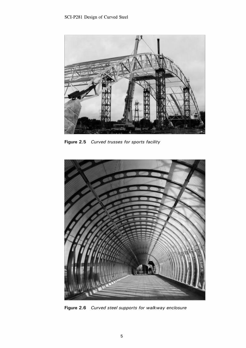
Modern building construction frequently uses curved steelwork for aesthetic appeal, structural efficiency or both. Typical examples are illustrated in Figures 2.3 to 2.7.
Figure 2.3 Curved roof steelwork to retail centre
Figure 2.4 Portal with curved rafters
SCI-P281 Design of Curved Steel
5
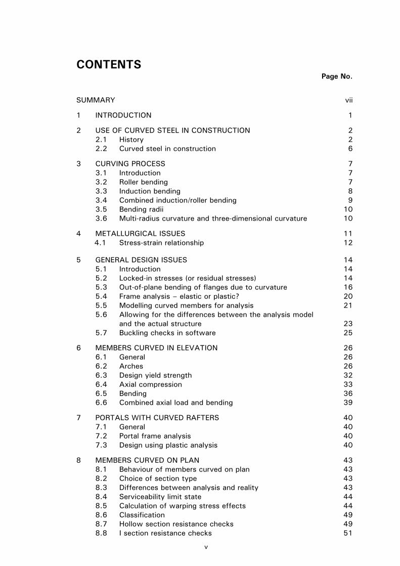
Figure 2.5 Curved trusses for sports facility
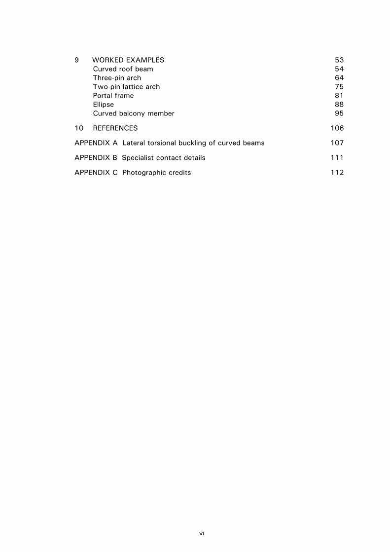
Figure 2.6 Curved steel supports for walkway enclosure

SCI-P281 Design of Curved Steel
6
2.2 Curved steel in construction The principal advantage of curved structural steel is its aesthetic appeal. It provides architects and designers with the opportunity to express a greater variety of forms than with straight members and makes exposed steelwork an attractive solution.
Curved steel structures are often designed to provide the users of the structure with natural light and a sense of spaciousness and grandeur in public facilities such as airports, stations, shopping malls and leisure centres. This has led to forms of structures in which relatively light curved steel trusses or arched frames support substantial areas of glazing. Even with clad structures, exposing the arching steelwork to view can enhance the sense of internal space.
Even for industrial and distribution buildings, curved roofs can provide an effective solution. Curved roofs avoid the aura of austerity that is often associated with “industrial warehouse” type buildings and may provide a solution that is attractive to local planners. Contrary to some expectations, curved steel structures need not be any more costly than other framed structures.
The additional cost of curving steelwork is usually small in relation to the overall cost of the structure, and can often be offset by savings in ridge detail and flashing costs and, for spans under approximately 25 m, by eliminating the need for an apex splice. Roof cladding on curved roof beams often does not need to be pre-curved, because many panels can follow the curvature of the roof during fixing without any special manipulation.
A curved external appearance can be produced by using faceted straight members, and by varying depth connections to the secondary members, but the additional fabrication costs for the faceted solution generally mean that a curved solution is more cost effective in addition to the aesthetic considerations.
Source of figure
Figure 2.7 Steel curved on plan

SCI-P281 Design of Curved Steel
7
3 CURVING PROCESS
3.1 Introduction Rolled steel sections are usually curved by a process using rollers or an induction bending process. The induction process is generally more expensive than the cold process, although smaller radii can be achieved and lighter sections can be curved. The different processes produce different finishes, depending on the member, the material and the radius. Structural designers are advised to contact the specialist companies that offer these processes (see Appendix B) for project-specific advice.
3.2 Roller bending The majority of curved steel for use in construction is curved by roller bending, which is a cold process.
Roller bending involves progressive bending of a section by passing the member through a set of bending rolls.
The rolls are shaped to the cross section of the steel member being curved (see Figure 3.1). Force is applied across opposing sets of rolls as shown in Figure 3.2, and more curvature is introduced on each pass through the rolls. The process is repeated until the required curvature is achieved.
Figure 3.1 Shaped rolls for circular hollow section
Figure 3.2 Three point bending

SCI-P281 Design of Curved Steel
8
Figure 3.2 shows the normal arrangement for a hollow section. When curving open (I or H) sections, the flanges can exert a considerable force on the web, leading to local web buckling if thin webs are not supported. For sections susceptible to this, additional rolls are located on the inside of the tension flange, which prevent the flange from pulling in towards the inside of the curve and crushing the web. The arrangement of rolls is shown diagrammatically in Figure 3.3, with additional rolls loading both sides of the tension flange. Figure 3.4 shows bending of an I section in progress, with additional rolls being used to prevent web buckling.
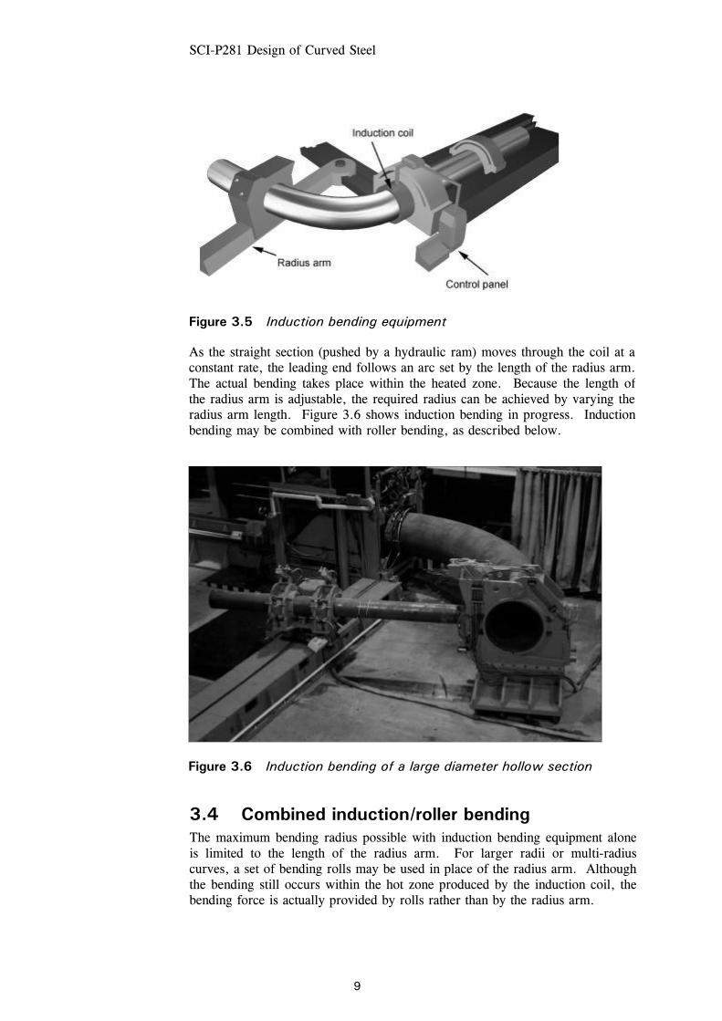
3.3 Induction bending In induction bending, the section (pipe, tube, hollow section or open section) to be curved is passed through an electric coil. The coil induces electrical currents in the section, which heat up the entire cross section over a narrow band (approximately 50 mm wide) to between 700 and 1050ºC. Air or water is used to cool the material immediately adjacent to the heated zone. The leading end of the section is clamped to a pivoted radius arm. The form of the equipment is shown in Figure 3.5.
Source of figure
Section A - AAdditional rolls
A
A
Figure 3.3 Arrangement of rolls to prevent web buckling of I section
Figure 3.4 Bending of an open section showing additional rolls to prevent web buckling
SCI-P281 Design of Curved Steel
9
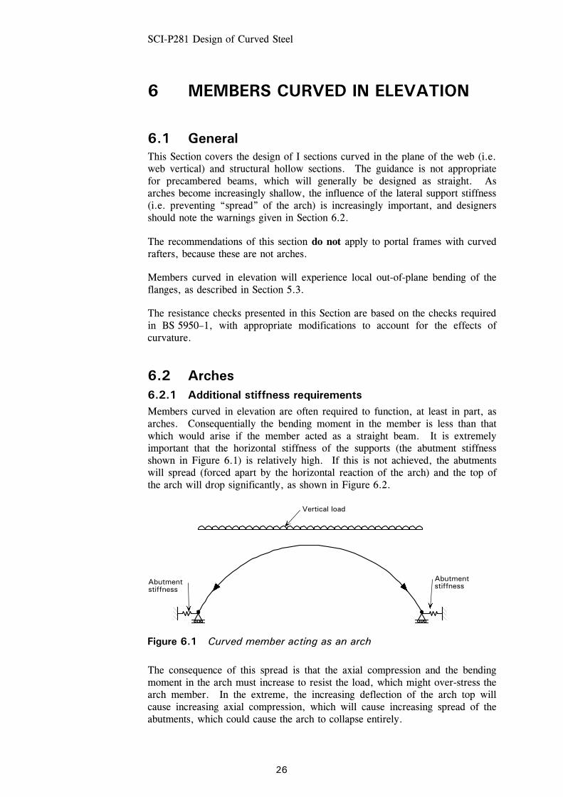
3.4 Combined induction/roller bending The maximum bending radius possible with induction bending equipment alone is limited to the length of the radius arm. For larger radii or multi-radius curves, a set of bending rolls may be used in place of the radius arm. Although the bending still occurs within the hot zone produced by the induction coil, the bending force is actually provided by rolls rather than by the radius arm.
Figure 3.5 Induction bending equipment
As the straight section (pushed by a hydraulic ram) moves through the coil at a constant rate, the leading end follows an arc set by the length of the radius arm. The actual bending takes place within the heated zone. Because the length of the radius arm is adjustable, the required radius can be achieved by varying the radius arm length. Figure 3.6 shows induction bending in progress. Induction bending may be combined with roller bending, as described below.
Figure 3.6 Induction bending of a large diameter hollow section

SCI-P281 Design of Curved Steel
10
3.5 Bending radii The “minimum radius” to which a section can be curved without significant distortion depends on the section properties of the member and the bending methods used. Advances in technology and curving techniques mean that minimum radii continue to be reduced. For this reason, tables of minimum radii are not included in this publication. However, the curving specialists can respond very quickly to requests regarding radii currently possible. The information can often be obtained directly from their websites (see Appendix B).
It is worth noting that the radius to which a structural section can be curved is unlikely to be the limiting factor in considering the use of curved steel for structural building applications.
When curving a member, there is always a straight length of material remaining at each end of the bar. If a perfect curve is required, these straight lengths must be cut off. In many circumstances, it is possible to retain these straight lengths, as the effect is not noticeable.
Specifiers are recommended to consult the curving specialists for further information on radii, finishes and costs. Discussion with specialists during the project design stage can often save considerable time and money later on.
3.6 Multi-radius curvature and three-dimensional curvature
In general, open sections, solid sections and hollow sections can be curved to single-radius curves, to multi-radius curves, to parabolic or elliptical curves or even to specified co-ordinates. Within limits, they can also be curved in two planes or to form spirals. There are, however, a number of physical constraints that limit the degree to which three-dimensional curvature is possible in practical terms. It is therefore important that any requirements for three-dimensional curves are discussed in detail at the enquiry stage.

SCI-P281 Design of Curved Steel
11
4 METALLURGICAL ISSUES
During the cold curving process, the material is strained beyond the elastic limit, and a permanent set is created in the material. In the case of a beam, the outside flange is stretched and the inner flange is compressed.
For normal low carbon steels, including structural steel used in orthodox structural applications, the strain undergone during the curving process is not detrimental, as after curving the material exhibits the same elastic characteristics in the elastic range as it did before bending. Some strain capacity has, however, been used, as described in Section 4.1.
The steel sections become strain hardened when using the cold curving process. The amount of strain hardening depends on the curvature achieved and the geometry of the section. A tensile test on a sample of steel that has been cold roller curved will show a small loss in ductility but a higher ultimate tensile strength. Even though there is a loss of ductility, for normal structural applications the effect is minimal and for most applications can be ignored.
There are no UK, European or American Standards that predefine or limit the radius to which structural sections can be cold curved for use in construction. However, BS 5500[2] (the UK pressure vessel Standard) permits carbon steel pressure components to be cold strained up to approximately 5% without the specific need for post-bend heat treatment. Similarly, some specifications for offshore construction allow cold-curving strains up to approximately 5%. In the absence of suitable construction industry Standards, it is not unreasonable to compare the requirements of what are, generally, much more exacting environments, with the needs of structural steelwork. It should be noted that the minimum radius to which most structural parallel flange (Universal) beams can be cold curved about their major axis equates to a maximum theoretical strain of much less than 5% – well in line with the strictest requirements elsewhere.
If the curved steel is to be used in an unusual environment such as low temperature, or subject to fatigue, mechanical testing can be carried out if required. Where significant ductility is required by the design, for example in plastic hinge locations, it is recommended that additional consideration be given to the loss of ductility due to the curving process. It may be possible to avoid hinges in the curved member or to have the actual material tested subsequently to determine its actual properties. Further information about the plastic design of curved members is given in Section 5.4.1.
Changes in mechanical properties also occur during hot bending but in this case it is the rates of temperature change in heating and post-bend cooling that provide the greatest influence, rather than the material strain, which is the dominant factor in cold bending. Quite significant changes to material properties can occur during the induction bending process. Post-bending heat treatment can usually be undertaken to restore the properties if necessary. The specialist contractors (Appendix B) should be consulted.

SCI-P281 Design of Curved Steel
12
4.1 Stress-strain relationship An idealised stress-strain graph for structural steel is shown in Figure 4.1. A more realistic stress-strain graph is shown in Figure 4.2, in which the yield point is not clearly defined. The lack of clear definition of the yield point in Figure 4.2 may arise from a variety of causes, including the chemistry of the steel, processing of the steel into the final product and post-processing such as roll-straightening at the mills.
Figure 4.3 shows a stress-strain plot similar to Figure 4.1 with a typical stress-strain path for cold bending. As the strain increases, the stress rises from A to the yield point at B then remains almost constant along the yield plateau as the section passes through the bending rolls. As the section passes beyond the bending rolls, the section unloads elastically, from C to D. When the section is next stressed, the stress-strain path rises elastically from D back up towards C, where it resumes the stress-strain path as in Figure 4.1. Some of the strain capacity (ductility) of the material has been used by the curving process.
Source of figure
Figure 4.1 Idealised stress-strain curve for structural steel
Figure 4.2 Typical actual stress-strain curve, without a clear yield point
Upperyield
Strain
Stress
Yield
0.2% Strain
Stress

SCI-P281 Design of Curved Steel
13
Source of figure
Figure 4.3 Stress-strain curve showing the effect of cold bending
B
A D
C
Strain
Stress

5 GENERAL DESIGN ISSUES
5.1 IntroductionThis Section reviews the following general design issues that affect curved steelmembers:
• Locked-in stresses from curving — their magnitude and effect.
• Out-of-plane bending of flanges.
• Frame analysis — should elastic or plastic analysis be used?
• Modelling issues when using software for analysis.
• Differences between the analysis model and the actual structure.
• Buckling checks in software.
Detailed guidance on the design of members curved in elevation, portal framesand members curved on plan is given in Sections 6, 7 and 8 respectively.
5.2 Locked-in stresses (or residual stresses)5.2.1 GeneralBoth induction bending and cold bending affect the residual stresses inmembers. The application of heat in the induction bending process allows therelaxation of any residual stresses; residual stresses in a member curved byinduction bending should be no more important than those in a straight member.
Cold curving changes the residual stresses in members. The magnitude of theseresidual stresses remaining after the curving process depends on the sectionproperties in the plane of curvature. Residual stresses do not affect thecross-sectional resistance of a section.
As a member passes through the bending rolls, the strain exceeds the yieldstrain, so that some plastic deformation occurs. As the member passes out ofthe bending rolls, it springs back elastically, so that there is equilibrium at thecross section. Figure 5.1 shows the stress distribution assuming that theextreme fibre strain reaches Kc, where C), is the yield strain of the steel. Figure5.1 also demonstrates that not all of the section reaches yield stress. Close tothe neutral axis, stresses remain in the elastic region. Figure 5.2 shows themoment induced by the curving, Mbr, and the elastic "spring-back" moment,MSb, which restores equilibrium such that:
Mbr + MSb = 0
14

SCI-P281 Design of Curved Steel
15
The “spring-back” moment is elastic, so the spring-back strains at the extreme fibres exceed yield strain. The residual stresses at the extreme fibre, pr, are therefore of opposite sense to the stresses induced by the bending rolls and are given by:
pr =
Z
M bs – py
To estimate the residual stresses, the bending moment caused by the bending rolls can be taken (conservatively) as the plastic moment Mp (= pyS).
The “spring-back” stresses, psb, are then given by:
psb Z = pyS and hence psb =
Z
Spy
σy σy
y yK
Stress Strain
D/2
K ε ε
D2
1 .K
Figure 5.1 Strain and stress – passing through rolls
Source of figure yp
M Zsb
yp M Zsb
yp
yp
p r
p r
Stress distributionin bending rolls
Residual stresses"Spring-back"stress distribution
Figure 5.2 Stresses from bending, “spring-back” and the residual stresses

SCI-P281 Design of Curved Steel
16
The residual stresses at the extreme fibre are therefore given by:
pr = psb – py = yy
pZ
Sp− =
− 1y Z
Sp
5.2.2 Stresses in members curved in elevation For Universal Beams curved in elevation, the ratio Sx / Zx is typically 1.12, so
pr = (1.12 – 1) py = 0.12 py
This level of residual stress is well within the range commonly found in straight beams due to the differential rate of cooling at the mills between the web and the flange tip. Because the curving process induces strains in excess of the yield strain, the curving process will remove the residual stresses from the straight beam. The residual stresses will therefore be limited to those caused by the curving process, and are not in addition to those in a straight beam.
For Universal Columns, Sx / Zx is commonly somewhat greater than for Universal Beams, giving pr up to 0.22 py for very heavy sections.
For structural hollow sections, pr ≈ 0.2 py typically.
5.2.3 Stresses in members curved on plan For I sections curved on plan, the ratio Sy / Zy is approximately 1.5, so
pr = (1.5 – 1) py = 0.5 py
If serviceability limit state (SLS) stresses are typically 0.6py, the additional residual stresses could lead to some plasticity at working load. However, in most cases deflections are likely to be the governing criteria and the SLS stresses will not exceed yield.
For structural hollow sections, the ratio Sy / Zy is lower and, typically, pr ≈ 0.2 py to 0.3py. For rectangular hollow sections (RHS) curved about the minor axis, pr is even less.
5.3 Out-of-plane bending of flanges due to curvature
The flanges of curved members subject to in-plane bending or axial loads must also resist the out-of-plane component of loads resulting from the curvature of the member. This applies to both open sections and box sections.
Figure 5.3 shows a typical I section subject to bending. Figure 5.4 shows a slice of the same I section, in which the slice is cut parallel to the web between the planes AA and BB. Due to the direct stresses σ1, the forces at the ends of these slices are not in equilibrium because they are inclined. This inclination causes a radial component of load all along the slice, which must be resisted by out-of-plane bending in the flange, as shown in Figure 5.5. A similar effect occurs in box sections, as shown in Figure 5.6.

SCI-P281 Design of Curved Steel
17
Source of figure
Figure 5.3 Curved I section resisting bending moment
Source of figure
SectionElevation
σ1σ1
σ1σ1
B A
B A
Figure 5.4 Slice of curved I section
Source of figure
σ1
σ1
σ1
σ1
θ
Radialloads
Radialloads
Bendingmoments
Elevation
Figure 5.5 Out-of-plane bending of I section flanges
Source of figure
σ1
σ1
σ1
σ1
Radialloads
Bendingmoments
B
Elevation
Figure 5.6 Out-of-plane bending of box-section walls
SectionElevation

SCI-P281 Design of Curved Steel
18
For the flanges of an I section in which the overall bending stress is σ1, the out-of-plane bending stress is derived from the loading shown in Figure 5.7, as follows:
Radial load on the flange = R
T 1σ
where:
R is the radius of curvature of the flange T is the thickness of the flange.
The bending moment, M, per unit length of flange at distance b from the flange tip is therefore given by
M =
2
21 b
R
Tσ
The elastic section modulus per unit length of flange, Z, is given by Z = 6
2T
Hence, the out-of-plane bending stress
σ2 = ZM
=
6
22
21
T
R
bTσ
= RT
b 213σ
(5.1)
For the flanges of box sections, conservatively assuming simple supports at the box corners, the maximum moment cannot exceed:
M =
8
21 B
R
Tσ
The out-of-plane bending stress is then given by
σ2 = RT
B
4
3 21σ
(5.2)
The out-of-plane stresses, σ2, are indicated in Figure 5.8.
Source of figure T
R
b
Radial load
Figure 5.7 Derivation of out-of-plane bending stresses

SCI-P281 Design of Curved Steel
19
Strictly, in equations 5.1 and 5.2 the radius R is the radius of the flange. In most practical cases, the difference caused by using the radius of the neutral axis of the beam will be negligible, because the effect of σ2 is accounted for via the von Mises yield criterion, where the influence of changes in σ2 is modest. Furthermore, when calculating the reduced section capacity due to these out-of-plane stresses, the calculations are based on the rather conservative use of the elastic modulus of the flange (rather than the plastic modulus). The calculation of the reduced section capacity is shown in Section 6.3.2.
In thin-walled circular hollow sections, the overall bending moments may cause a reduction in capacity due to ovalisation. Ovalisation is the slight flattening and widening of the profile as shown in Figure 5.9. Ovalisation under an applied bending moment occurs in both curved and straight members. It will generally not be a concern for orthodox members curved by normal processes for use in orthodox buildings, and is not considered further in this document.
5.3.2 Effect of out-of-plane bending stresses The out-of-plane loads reduce the cross-sectional resistance of a member because of the transverse bending stresses, σ2, and are accounted for by use of the von Mises relationship. However, at the flange tips of an I section (see Figure 5.5), the out-of-plane bending stresses are zero. Therefore, in an I section, these stresses do not affect the resistance to either lateral torsional buckling, Mb, or lateral buckling about the minor axis, Pcy, because both are based on the stresses at the tips of the flanges. The out-of-plane bending stresses do reduce the in-plane buckling resistance, Pcx, and the local bending resistance, Mcx, and must be taken into account as explained in subsequent Sections. Out-of-plane bending stresses should always be taken into account when calculating any resistance of a hollow section.
Some out-of-plane stresses are locked in during the cold rolling process. These are small enough to be ignored.
Source of figure
Box section
2σ 2σ
I section
Figure 5.8 Out-of-plane stresses in flanges
Source of figure Original circular cross section
Figure 5.9 Ovalisation of a circular hollow section

SCI-P281 Design of Curved Steel
20
5.4 Frame analysis – elastic or plastic? 5.4.1 Frames with members curved in elevation Elastic frame analysis may be used for any frame with members curved in elevation, provided that the geometry of the curved elements is allowed for as described in Section 5.5.
Plastic analysis, which is the most common analysis method for single-storey portal frames constructed with straight members, can also be used for single-storey portal frames with rafters having modest curvatures. The guidance in this publication is appropriate for frames with curved rafters, which, if made with straight members, would have modest rafter slopes, say of the order of 10º.
Some ductility is lost during the curving process, and this should be considered when assuming that plastic hinges can develop in the members. In frames with the modest curvatures described above, constructed with typical rafters, the strain during the curving process is typically of the order of 1%. It has been suggested that strains up to 5% have no significant effect on the material properties[3], but a strain limit of 2½% appears to be more appropriate, based on anecdotal UK evidence. Rafters of modest curvature will fall well within this limit.
An alternative approach is to reduce the allowable rotation at hinge locations, and check that the collapse mechanism does not rely on rotations greater than the (reduced) limit. In ordinary (straight) steelwork, 6o of rotation at a plastic hinge is generally considered to be a maximum allowable limit. For a mildly curved member, a limit of 3o is recommended, to allow for the strain that has already taken place. The rotations predicted by the analysis should be checked against this reduced limit. This should not be seen as an unduly onerous reduction as, in practice, even this reduced limit is unlikely to be critical in frames with orthodox geometry.
Plastic hinges should not be allowed in members curved to small radii, unless the properties of the “as curved” steel are tested.
5.4.2 Frames with members curved on plan Elastic analysis should be used for all structures with members curved on plan. It is recommended that plastic analysis is not used for members curved on plan, for the following reasons:
• Members curved on plan are often governed by deflection criteria, either from code limits or to avoid unsightly visible deflections. There is no point in using plastic design for a more economical ultimate limit state (ULS) design if SLS design governs.
• Outstands of flanges that are curved on plan are less stable than for straight members.
• Large torsional displacements may result if plasticity occurs and this could have disproportionately weakening effects on the stability of the frame.

SCI-P281 Design of Curved Steel
21
5.5 Modelling curved members for analysis 5.5.1 General Computer software can normally only model straight lengths of elements. It is possible to use a series of short straight segments to model a curved member (see Figure 5.10) but there are several issues that should be considered. The major issues are discussed below.
5.5.2 Number of straight segments representing a curved member
The accuracy of the model will improve with the number of analysis elements, provided that these are chosen so that the off-set between the curved member and the segments is minimised. As a guide, when modelling a semi-circular member, five segments will give a rather coarse model, ten segments will give a reasonable model and twenty segments will give a very good model.
The choice of the number of elements will depend largely on the curvature of each curved member. For members with only very slight curvature, there is normally no need to divide the model into a large number of analysis elements, as the differences between the analysis model and the actual structure can be accounted for simply. In the curved truss chord shown in Figure 5.11, the small offset of the real curved member from the single straight line analysis element between nodes can be allowed for by adding the appropriate moment in the strength check of the boom, as explained in Section 5.6. However, as the curvature increases, or as the need for accuracy increases, more segments are needed to model each member.
Source of figure
Figure 5.10 Straight segments to model curved member AB
Source of figure
Figure 5.11 Straight line model of a truss with a curved steel chord
Straight segments
BA
Intermediatenodes
P1
e 1
e
P2
P
P
3
4
e
e2 3
4

SCI-P281 Design of Curved Steel
22
5.5.3 Support conditions It is important that the actual support conditions of each member are modelled as accurately as possible. It must be remembered that the actual support conditions vary considerably among all three directions. In most structures, the effect of the support conditions has a much greater influence on the performance of curved members than on the performance of straight members. Two examples are:
Members curved in elevation
If a member is curved in elevation and the support has significant stiffness in the line of the member (i.e. the supports are stiff laterally and prevent “spread”), the member will tend to behave as an arch. If the support stiffness is modelled inaccurately, the model will give inaccurate results. If the model over-estimates this stiffness at the supports, the arching action will be over-estimated. This could result in a serious under-estimate both of the vertical deflection of the arch and of the bending moment induced in the member. Full lateral fixity should not be assumed and modelled without careful consideration of the real support stiffness. Support stiffness for arches is discussed in more detail in Section 6.4.
Beams curved on plan
Beams curved on plan have to resist the torsions resulting from the curvature. If the end connections are not stiff in the plane of the torsion, the beam will be free to twist and cause deflections. These may be unsightly in themselves and may cause cracks in the nearby finishes. Particular care should be taken in the stiffness assumed in each plane, and to ensure that analysis assumptions are compatible with the real details.
5.5.4 Warping stiffness Warping stiffness is the stiffness resisting twist that comes from direct stresses along the member, in contrast with pure torsional stiffness that comes from shear stresses around the cross section. An example of resistance to twisting by warping is where a twisting moment (torque) is applied to a beam at midspan of an I section. The applied moment is resisted mainly by lateral bending of the flanges, as shown in Figure 5.12, rather than by pure torsion. Both warping and torsion occur in most practical cases. Warping will resist most of the torsion in many cases where an open section member is short and the support conditions allow lateral bending moments to develop.
Most software will not include warping stiffness in line elements. This means that the stiffness of the member against twist is under-estimated and there will be consequential errors in the evaluation of stresses.

SCI-P281 Design of Curved Steel
23
5.5.5 Interpretation of analysis results The results of a computer analysis are normally given in local element axes. It should be remembered that these will not be the axes of the plane of the cross section of the actual member at the node points. This is because the local element axes are based on the line from node to node of the straight element, which cannot be tangential to the actual curved member at the nodes. This means that to find the torque and moment in the actual section, the computer output must be resolved about the different axes. It also means that the moment and torque output from one element at a node will be slightly different from the output from the other element. In practice, where a reasonable number of elements has been used to model each curved member, the differences will be small enough to be covered by slightly conservative use of the worst values of moment and torque occurring at each node.
Particular care should also be taken with deflection output. Deflections are frequently quoted relative to the ends on the analysis element, rather than absolute deflections relative to the supports of the frame.
5.6 Allowing for the differences between the analysis model and the actual structure
5.6.1 General Significant differences between the analysis model and the actual structure must be accounted for in the strength checks of the members. The following Sections illustrate how to include for the effects of modelling curved members with straight elements, and for the influence of warping stiffness.
Source of figure
a) Undeformed beam
M
TM h
TM h
h
MT
b) Torque on section
d) Flanges deformed by lateral bending
Tc) Horizontal forces equivalent to applied torque, M
Figure 5.12 Resistance to twist by warping

SCI-P281 Design of Curved Steel
24
5.6.2 Offsets Where the analysis model is a series of straight segments used to simulate a curved member (commonly used when analysing a pin-jointed truss), the effect of the offset between the straight and the curve must be included. In axially loaded members, the difference can be included by adding a moment equal to the axial load, P, multiplied by the offset, e, as shown in Figure 5.13. In trusses with continuous curved members, the simple calculation demonstrated in Figure 5.13 gives a conservative estimate of the additional moment if only one straight segment is used between points of intersection of the chord and the bracings, as shown in Figure 5.14. An alternative approach, shown in Figure 5.15, is to consider the continuity of the chord, which produces a smaller additional moment to be allowed for in the design of the member.
Source of figure
Figure 5.13 Additional bending moments in curved chords
Source of figure
Figure 5.14 Simple estimate of additional moments in continuous
chords
Source of figure
Figure 5.15 More accurate distribution of additional moments in
continuous chords
e
P Structure
pe
Additional bending to be addedto the analysis output
P1
e 1
e
P2
P
P
3
4
e
e2 3
4 p e
P1
e 1
e
P2
P
P
3
4
e
e2 3
4 ep

SCI-P281 Design of Curved Steel
25
5.6.3 Warping Warping is described in Section 5.5.4. Most frame analysis software will not include the effect of warping. This will have no effect on the analysis of circular hollow sections (CHS) because their warping stiffness is zero. It will have an insignificant effect on rectangular hollow sections (RHS) because their warping stiffness is small and their torsional stiffness is high. However, the warping stiffness of I sections is very important, as their torsional stiffness is low.
The omission of the warping stiffness when analysing I sections will lead to an over-estimate of deflections and of the shear stresses from torsion. The over-estimate of the torsional stresses will normally lead to an under-estimate of the cross-sectional resistance of the member. However, the omission of the warping stresses, which are predominantly longitudinal direct stresses, may lead to a serious over-estimate of the resistance to lateral-torsional or lateral buckling. For this reason, the warping stresses should be included in the resistance checks as described in Sections 8.5.3 and 8.5.4.
5.7 Buckling checks in software Most structural analysis software includes modules for checking member resistance according to BS 5950–1. However, these facilities may be very misleading for the following reasons:
• Most software packages do not have resistance checks appropriate for curved members.
• BS 5950–1 considers only straight members, which gives unsafe results if applied to certain cases of curved beams.
• Some software packages perform the stability check on the length of each straight segment. Where more than one straight segment is used to model a curved element, this will lead to a major error in the value of the effective length.
SCI-P281 Design of Curved Steel
26
6 MEMBERS CURVED IN ELEVATION
6.1 General This Section covers the design of I sections curved in the plane of the web (i.e. web vertical) and structural hollow sections. The guidance is not appropriate for precambered beams, which will generally be designed as straight. As arches become increasingly shallow, the influence of the lateral support stiffness (i.e. preventing “spread” of the arch) is increasingly important, and designers should note the warnings given in Section 6.2.
The recommendations of this section do not apply to portal frames with curved rafters, because these are not arches.
Members curved in elevation will experience local out-of-plane bending of the flanges, as described in Section 5.3.
The resistance checks presented in this Section are based on the checks required in BS 5950–1, with appropriate modifications to account for the effects of curvature.
6.2 Arches 6.2.1 Additional stiffness requirements Members curved in elevation are often required to function, at least in part, as arches. Consequentially the bending moment in the member is less than that which would arise if the member acted as a straight beam. It is extremely important that the horizontal stiffness of the supports (the abutment stiffness shown in Figure 6.1) is relatively high. If this is not achieved, the abutments will spread (forced apart by the horizontal reaction of the arch) and the top of the arch will drop significantly, as shown in Figure 6.2.
The consequence of this spread is that the axial compression and the bending moment in the arch must increase to resist the load, which might over-stress the arch member. In the extreme, the increasing deflection of the arch top will cause increasing axial compression, which will cause increasing spread of the abutments, which could cause the arch to collapse entirely.
Source of figure
Figure 6.1 Curved member acting as an arch
Vertical load
Abutmentstiffness
Abutmentstiffness

SCI-P281 Design of Curved Steel
27
Under axial compression, the member will shorten, which also reduces the height of the arch, again leading towards collapse unless the effect is accounted for in design.
Both effects are more critical in arches with low rises compared with their span. In the extreme, a flat arch with very low support stiffness behaves as a simply supported beam.
This reduction in the height of the arch can be considered in two different ways. The first and simplest approach is to consider how the reduction in height must be limited to ensure that normal first-order (small deflection) frame analysis is appropriate. The second, more complicated, approach is to find the actual deflection and axial compression resulting from the increasing spread of the abutments as the arch height reduces. This requires a second-order (large deflection) analysis. This publication considers only the first approach – that of defining a limit such that first-order analysis is appropriate.
If the deflection of the apex of the arch under ultimate limit state loading is less than 2½% of the height of the apex above the line of thrust between the abutments, first-order analysis will be sufficiently accurate and second-order effects may be ignored. This assumes (as is commonly the case) that the analysis software takes into account the axial shortening of the member due to the compressive stress. This may be verified by applying a load to a strut, as shown in Figure 6.3, and checking that the software indicates that the strut shortens.
Source of figure h
h
δ
Deflected shape
Initial shape
Figure 6.2 Reduction of arch height under load
Source of figure
Figure 6.3 Simple analysis model to check axial shortening

SCI-P281 Design of Curved Steel
28
The simple check of arch deflection also assumes that a reasonable estimate of support stiffness has been used in the analysis, which is matched in the real structure. The importance of support stiffness increases as the rise:span ratio decreases.
Where the apex deflection is greater than 2½% of the height of the arch, the increase in the arch force and the coincident bending moment should be considered.
6.2.2 Load cases The critical load case for an arch is not always easy to identify. It is important that the different cases are considered carefully, taking into account both the loading and the horizontal stiffness of the abutments. In many cases, the load case with maximum bending moment is the critical load case. To allow rapid initial sizing, the calculation of approximate maximum axial forces and moments is demonstrated below.
Maximum axial compression
The maximum axial compression in an arch normally occurs when there is a uniformly distributed load across the full span, as shown in Figure 6.4. If the arch is parabolic in elevation, with abutments “fixed” in position, the horizontal component, FH, of the compressive force in the arch is approximately
= h
wL
8
2
= h
wL8
2
The maximum compressive force occurs at the springing of the arch and is the vector sum of the horizontal component, FH, of the compressive force and the vertical reaction, Fv:
Fmax = 2V
2H FF +
where FV = 2
wL for the simplified loading shown in Figure 6.4.
Source of figure
Figure 6.4 Parabolic arch under full span uniformly distributed load
midspanatarchofHeightbeamsupportedsimplyaofmomentbendingMidspan
≈≈HF
L
F
h
w/unit length

SCI-P281 Design of Curved Steel
29
The bending moments in this load case are usually small, provided that the abutments do not spread significantly. However, if the abutments can spread significantly, and the arch is stiff in major axis bending, the bending stress will become important.
Maximum bending from gravity loads
The maximum bending from gravity loads normally occurs from partial loading, as shown in Figure 6.5, in which the arch is loaded over only half of the span.
The half span loading of w/unit length can be expressed as the sum of full span loading of (w/2)/unit length plus asymmetric loading of downward and upward loads of (w/2)/unit length, as shown in Figure 6.6. By considering the applied loads in this way, an approximate axial load and bending moment may be calculated for initial sizing.
Source of figure
h
w/unit length
L
L/2 L/2
Figure 6.5 Parabolic arch with half span loading
Source of figure
w/2
w/2
w/2
+
=
=w
(w/2)/unit length
(w/2)/unit length
(w/2)/unit length
Figure 6.6 Equivalent loading to half span loading

SCI-P281 Design of Curved Steel
30
The compressive force in the arch is caused by the full-span component of the loading. The bending moment on a simply supported beam is shown in Figure 6.7.
Therefore, the horizontal component, FH, of the compressive force in the arch is approximately:
= h
wL
16
2
= h
wL16
2
The bending moment in the arch is approximately equal to the bending moment from the asymmetric component of the loads, as shown in Figure 6.7. This is at its maximum at the quarter points.
Therefore bending moment, M ≈ 8
22
2
Lw
= 64
2wL
This type of partial loading normally gives the greatest bending moment in an arch, although it is probable that the worst bending will occur with partial loading up to a point that is not exactly at half span, depending on the distribution of the loading and the geometry of the arch.
Maximum bending from wind loads
Wind loads on arches are asymmetrical when the wind blows along the span of the arch. A possible wind pressure diagram is shown in Figure 6.8.
Source of figure
(w/2) /unit length
L
L/2L/2
wL²/16
wL²/64
BMD drawn oncompression side
BMD drawn oncompression side
(w/2) /unit length
(w/2) /unit length
Figure 6.7 Bending moment diagrams
midspan at arch of Height beam supported simply a of moment bending Midspan
H ≈ F

SCI-P281 Design of Curved Steel
31
The point of change from pressure to suction is likely to be uncertain, so more than one case, within the envelope of cases shown in Figure 6.9, may need to be considered in sensitive designs.
As a guide to estimating the magnitude of the bending moments induced, a load case with equal pressure and suction is shown in Figure 6.10.
Source of figure
Arch
Suction
Pressure
Wind direction
Figure 6.8 Possible wind pressure diagram
Source of figure Wind direction
Suctionenvelope
Pressureenvelope
Figure 6.9 Possible envelope of wind pressure
Source of figure Suctionw/unit length
Pressure w/unit length
0.5L 0.5L
L
wL²/32
Figure 6.10 Approximate bending moment from wind loads from one direction

SCI-P281 Design of Curved Steel
32
The length of the arch around its curve is taken as “L”, so the approximate bending moment is given by:
M = 82
w2
L
= 32
w 2L
6.3 Design yield strength 6.3.1 General When members are curved in elevation, the out-of-plane bending stresses in the flanges (see Section 5.3) may be accounted for by calculating a reduced design strength, pyd. This reduced design strength is used when calculating Mcx or Pcx of I sections, and in all resistance calculations for hollow sections. Table 6.1 summarises where the reduced value should be used, although pyd may be used (conservatively) in every check.
Table 6.1 Design strength to be used in resistance calculations for members curved in elevation
Members curved in elevation
Resistance calculation
I sections Hollow sections
Mcx pyd pyd Pcx pyd pyd Mcy py* pyd Pcy py pyd Mb py pyd
py is the design strength, as defined in Clause 3.1.1 of BS 5950–1.
pyd is a reduced value of design strength, as given in Section 6.3.2 below.
* If py is used for the minor axis cross-sectional resistance, the resistance should be limited to the elastic capacity, pyZy. The plastic modulus Sy may only be used with the reduced design stress, pyd.
6.3.2 Calculation of reduced design strength for I sections curved in elevation
When curved I sections are loaded, out-of-plane bending stresses will be induced in the flanges, as described in Section 5.3. Where these out-of-plane bending stresses are tensile, they will combine with the longitudinal compressive stress to reduce the effective yield of the section. To allow for this, a reduced design strength, pyd, must be calculated, as follows:
i. Calculate the out-of-plane bending stress, σ2, from Section 5.3 (equation 5.1)
ii. Calculate the reduced design strength, pyd, from:
pyd = 2
32
3 2
50
22
22 σ+
τ−
σ−
.
yp (6.1)

where:
a2 is the out-of-plane bending stress calculated above. To calculate themaximum reduction in design strength, 02, should be taken as negativeif p is taken as positive.
t is the coexistent shear stress. In most cases, this can be ignoredbecause the shear stress in the flanges is small. In addition, this methodonly considers the combination of compressive longitudinal stresses andtensile out-of-plane bending stresses that occur on one face of theflange, which is conservative. On the other face of the flange, there isa partly compensating combination of compressive longitudinal stressesand compressive out-of-plane bending stresses, which is ignored in thisapproach.
The formula above is derived from the von Mises formula:
a02 — a12 + a22 — a1a2 + 3t2
which can be expressed as:
2 — 2 2Py — Pyd + 02 Pyd02 + .)t
6.3.3 Hollow sectionsAll resistances should be calculated using the reduced design yield, Pyd,calculated as described in Section 6.3.2. In determining the reduced designstrength, the out-of-plane bending stresses, 02, should be calculated usingequation 5.2 in Section 5.3.
6.4 Axial compression6.4.1 GeneralFor simplicity in design, it is desirable to use the same design process forcurved members as for straight members. The following Sections give guidanceon effective lengths and design strengths.
6.4.2 Effective lengths in planeEffective lengths for buckling in plane are given in Figure 6.11 to 6.14, whichare taken from DIN 18 800 Part Four types of arch are shown. Eachfigure shows the relationship of h:l (arch rise:span) and , the effective lengthfactor. In every case, the effective length is the developed length from thesupport to the crown of the arch (shown as s in the figures), multiplied by .
Each figure shows the effective lengths for two forms of curve:
• circular (the Kr curve)
• parabolic (the a curve).
33

SCI-P281 Design of Curved Steel
34
Source of figure 1.3
0.50.40.30.20.100.8
0.9
1.0
1.1
1.2
l
sKr
Pa
β
h
h/l
Two-pin arch
Figure 6.11 Two-pin arch
Source of figure
0.50.40.30.20.10
l
s
β0.9
Fixed supports
0.8
0.7
0.6
0.5
0.4
Pa
Kr
h
h/l
Figure 6.12 Fixed supports
Source of figure 1.3
0.50.40.30.20.100.8
0.9
1.0
1.1
1.2
l
s
Pa
β Kr
h
h/l
Three-pin arch
Figure 6.13 Three-pin arch
Source of figure
0.50.40.30.20.10
l
s
β0.9
0.8
0.7
0.6
0.5
1.0
Fixed supports,single pin
Kr
Pah
h/l
Figure 6.14 Fixed supports, one-pin arch

SCI-P281 Design of Curved Steel
35
The graphs assume no spread of the supports. This is a key assumption, particularly at low rise to arch ratios, where spread of supports could lead to catastrophic failure of the arch. For this reason, a grey zone has been overlaid in each figure, at rise to span ratios less than 0.1. For arch geometry falling in this zone, designers are reminded of the need to pay careful attention to the effects described in Section 6.2.1.
From Figure 6.11, and assuming a rise to span ratio of 0.4, the effective length of a circular arch is 1.1 × (developed length from support to apex).
Similarly from Figure 6.12, for the same arch form and rise to span ratio, the effective length is 0.7 × (developed length from support to apex).
For normal construction, being neither fully fixed nor truly pinned, an effective length between the two extremes could be assumed, and an effective length of 1.0 × (developed length from support to apex) is suggested. In each case, this assumes no significant spread of supports.
The reason for the fundamental distance being from abutment to apex in continuous arches is shown in Figure 6.15. For an arch with insignificant spread of the supports, buckling into the arch at one point is only possible if there is buckling out of the arch elsewhere. This asymmetric buckled form is shown in Figure 6.15
If the supports can spread significantly, the use of Figure 6.11 to 6.14 is not appropriate, as the figures assume no spread of supports. As supports spread, the effective length will become greater, tending to the full length of the arch in the extremes of support spread or flatness of the arch.
It is not appropriate to calculate the effective length for buckling based on the distance to the point of inflection of either the bending moment diagram or the deflected shape. Neither the bending moment diagram nor the deflected shape necessarily gives the buckling mode (and hence effective length) of the arch.
6.4.3 Effective lengths out of plane The effective lengths for out-of-plane buckling may be assessed in the same way as normally used for straight members, but using the length around the curve. Normally, the effective length should be taken as:
1.0 × (developed length between points of restraint to both flanges).
Source of figure Undeformedshape
Buckledshape
Figure 6.15 Approximate buckled form for a normal continuous arch
SCI-P281 Design of Curved Steel
36
6.4.4 Design compressive strengths for I sections curved in the plane of the web
Buckling in the plane of the web (major axis buckling)
The design compressive strength, pcx, for buckling in the plane of the web may be taken as pc for a straight member but using a reduced design strength pyd as given in equation 6.1 in Section 6.3.2.
Buckling in the plane of the flanges (minor axis buckling)
The design compressive strength, pcy, for buckling in the plane of the flanges may be taken as pc for a straight member with no reduction of design strength.
6.5 Bending 6.5.1 Cross-sectional resistance of I sections curved in
elevation For major axis cross-sectional resistance, the design strength should be reduced to account for the out-of-plane bending stresses as described in Section 6.3.2. If the minor axis cross-sectional resistance is checked based on the first-yield resistance, i.e. Mcy = py Zy, the design strength may be taken as py because the out-of-plane bending stresses are zero at the edge of the flange outstands (the critical point for elastic capacity). If the minor axis cross-sectional resistance is checked using the plastic resistance, i.e. Mcy = pyd Sy, the design strength should be taken as pyd, because the plastic capacity depends on yield throughout the section, including the zones affected by out-of-plane bending stresses. 6.5.2 Buckling resistance of I sections curved in elevation The resistance of straight members to lateral torsional buckling is given in Section 4.3 of BS 5950–1 as Mb. A modified approach must be used for beams curved in elevation because the curvature affects the stability (lateral torsional buckling resistance) of the member. The derivation of the modified approach is given in Appendix A, and the design method is described in Section 6.5.3.
Beams that are curved in elevation and carry moment such that the convex flange is in compression, as shown in Figure 6.16, are less stable than if they were straight. Conversely, beams that are curved in elevation and carry moment such that the concave flange is in compression, as shown in Figure 6.17, are more stable than if they were straight. However, in the latter case, it is recommended that the resistance is assumed to be no greater than for a straight member, for the reasons given in Appendix A.1.
Design strength
Lateral torsional buckling is governed by onset of yield at the edge of the flange outstands due to lateral bending. At the edge of the outstand, the stresses from out-of-plane bending, described in Section 5.3, are zero. Therefore the buckling strength, pb, need not be reduced to allow for out-of-plane bending stresses.

37
6.5.3 Modified lateral torsional buckling resistance BS 5950–1 assumes that members are straight before loading. To allow the Standard to be used for curved members, the value of LT must be modified to calculate the correct resistance. The modified value of LT is used in Clause 4.3.6.5 of BS 5950–1 to calculate pb and hence Mb.
For all segments of members in which the compression flange is the convex flange of a curved member, it is important that the modified LT is used, because use of LT directly from BS 5950–1 will over-estimate the member resistance.
For segments of members in which the compression flange is the concave flange of a curved member, it is recommended that the member is designed as if it were straight.
of figure
Figure 6.16 Convex flange in compression – less stable than if
straight
Source of figure
Figure 6.17 Concave flange in compression – more stable than if
straight
R
Compression
Tension
MM
R
Compression
Tension
MM

38
For curved members where the convex flange is in compression, the modified value of LT, for use in Clause 4.3.6.5 of BS 5950–1, can be calculated as follows:
LT =
yE
2cx
pMEπM
(6.2)
in which:
Mcx is the moment capacity of the section, assuming low shear, as given by Clause 4.2.5.2 of BS 5950–1
py is the design strength as given by Clause 4.1.3 of BS 5950–1
ME is the elastic critical buckling moment for a curved member, given by
ME = 2
14 22
22
ab
RLRc
Rc
(6.3)
where:
a = E Iy
b = GJ + 2 EH / L2
c = a + b
R is the radius of the neutral axis of the member when loaded. R is positive when the convex flange is in compression
where:
E is the modulus of elasticity of steel (205 000 N/mm2)
Iy is the second moment of area about the minor axis
G is the shear modulus = 12
E
J is the torsional constant of section
H is the warping constant of section
L is the distance between torsional restraints
v is Poisson’s ratio (0.30).
Although the radius will change as load is applied, the effect on ME is small if the member has significant curvature, so this effect can be neglected in most cases. R may therefore be taken as the unstressed curvature. Where the outer flange is in compression, the stresses tend to straighten the member, which increases the stability. Therefore, it is always safe to take R as the unstressed radius of curvature.

SCI-P281 Design of Curved Steel
39
6.6 Combined axial load and bending 6.6.1 Cross-sectional capacity The cross-sectional capacity of tension members with moments may be checked using Clause 4.8.2 of BS 5950–1. The cross-sectional capacity of compression members with moments may be checked using Clause 4.8.3.2 of BS 5950–1. Where appropriate, the values of Mcx and Mcy should be modified in accordance with Table 6.1.
6.6.2 Member buckling resistance The member buckling resistance may be checked using Clause 4.8.3.3.1 Simplified method of BS 5950–1, but with Pcx, Pcy, and Mb modified, where appropriate, in accordance with Table 6.1.

SCI-P281 Design of Curved Steel
40
7 PORTALS WITH CURVED RAFTERS
7.1 General Increasing numbers of portal frames are being constructed with curved rafters. Curved rafters might be chosen for aesthetic appeal, or for the simplicity of construction. The simplicity arises from avoiding the need for the ridge detail in the sheeting and the ridge splice in the rafters. Universal Beams are commonly used for the curved rafters.
When curving a member, there is always a straight length of material remaining at each end of the bar. Where a perfect curved member is required, these straight lengths must be cut off. However, for greatest economy, these straight lengths should be included in the final member length. This avoids wasting the straight end lengths and making the additional cuts. In practice, the effect of curvature at the end of rafters is difficult to observe, so it is possible that retaining the straight lengths will be acceptable. Straight lengths in the haunch region will also simplify fabrication of the haunch.
The extent of the straight length depends on the member size and degree of curvature. Designers wishing to utilise the straight lengths should consult specialist contractors for further information (see Appendix B).
7.2 Portal frame analysis Design based on an elastic analysis may be used for all structures with curved members, including portal frames. The member resistance checks for structures designed elastically are described in Section 6. Plastic analysis is common for portal frames with straight members, and may also be used, within limits, to analyse portal frames with curved rafters.
7.3 Design using plastic analysis When considering the plastic analysis of portal frames with curved rafters, the following differences from frames with straight members need to be noted and accounted for in design as necessary:
• Rotation of plastic hinges.
• Stability adjacent to plastic hinges.
The following guidance relates to portal frames of modest curvature, where an equivalent frame with straight members would have no more than a 10º roof slope.
7.3.1 Rotation of plastic hinges As described in Section 5.4.1, some ductility is lost in the curving process. For modest curvatures, the strain is small, and anecdotal evidence suggests that the change in material properties is small enough to be ignored. If detailed consideration is required, Section 5.4.1 proposes limiting the maximum rotation at plastic hinges to 3º.

SCI-P281 Design of Curved Steel
41
In many frame designs, serviceability limit state checks (particularly for column top deflection) result in the use of larger sections, which in turn may mean that the frame remains elastic at ultimate limit state (ULS), i.e. no hinges form. Hinges that form in the rafter above ULS need not be considered. Similarly, if a frame is sized such that the only hinge to form in the rafter is the last hinge, completing the mechanism, no restriction on rotation need be imposed.
7.3.2 Stable lengths adjacent to plastic hinges There are no test results for the stable length of members with plastic hinges, which casts some doubt on whether it is appropriate to use “straight” rules for curved members. However, the lateral torsional buckling stability of a section is increased by curvature when the compression flange is on the inside of the curve (the concave flange). This means that the resistance to lateral torsional buckling of hinges in the haunch regions is increased where the curve of the rafters is as shown in Figure 7.1. Despite this effect, due to the lack of test results for plastic hinge behaviour in curved members, it is recommended that the stable length is never assumed to be greater than for straight members.
This cautious approach is because there is no simple method yet available for treating the destabilising effect of the radial compression in the web when the inner flange is in compression and the outer flange is in tension. Although, for the curvatures common in portal frames, the compression is small, it remains unwise to increase the stable length of the member. This radial compressive force should also be remembered when checking the need for stiffeners according to BS 5950–1 Clause 5.2.3.7.
In the zone around the apex of the rafter, the sagging bending moment causes compression in the convex face of the member, which reduces the member resistance. It is recommended that plastic hinges should not be allowed to form when the applied bending moment produces compression on the convex face of the member. For the structure shown in Figure 7.1, however, the hinge in the apex zone will be the last to form under gravity loading, and is therefore not required to rotate. In these circumstances, the requirement is simply that the reduced member resistance must exceed the applied moment.
In general, rotating hinges below ULS should not be allowed where the bending moment produces compression on the convex face.
Source of figure
R
Figure 7.1 Typical curved rafter portal frame

SCI-P281 Design of Curved Steel
42
One form of curved rafter that is sometimes used is shown in Figure 7.2. In the eaves region of this frame, the hogging bending moment at the eaves produces compression on the inside, convex, flange. In this case, the resistance to lateral torsional buckling is reduced. In these circumstances, the stable length checks for straight members given in BS 5950–1 may not be conservative and plastic hinges in the eaves region should be avoided.
In the form of structure shown in Figure 7.2, this can be achieved by ensuring that the relative sizes of rafter and columns mean that all hinges rotating below ULS are in the columns, or by designing the complete frame elastically.
7.3.3 Use of finite element analysis
It is possible to produce finite element analyses of curved members that seriously over-estimate the lateral torsional buckling resistance of the member. Therefore, finite element analysis should only be used after background research into the problems and calibration of the analysis results.
Source of figure
R
R R1 1
2
Figure 7.2 Doubly curved rafter – design should ensure no hinges in the rafter below ULS

SCI-P281 Design of Curved Steel
43
8 MEMBERS CURVED ON PLAN
8.1 Behaviour of members curved on plan Members curved on plan are subject to unusual load effects, and need careful design and detailing in order to provide satisfactory service. It is particularly important that the actual support conditions are modelled in the analysis, in all planes. The supports for members curved on plan are generally fixed in the vertical plane, with the member itself acting as a fixed-ended beam. Vertical loads are applied eccentric to the straight line between supports, and therefore produce twisting of the member. The end connections may be detailed to resist this torque, or may be considered free to rotate, producing quite different bending moments and deflections. I sections resist twisting primarily by their stiffness against warping (see Section 5.5.4), which depends on the lateral bending resistance of the flanges; the support conditions in the horizontal plane are therefore important. When fully built-in supports are assumed in design, actual deflections could be greatly increased by any slip or twist of the end connections in the real structure.
8.2 Choice of section type Where members are curved on plan, it is simplest to use structural hollow sections or box sections, because they have high torsional stiffness and are not sensitive to lateral torsional buckling. More generally, the following guidance can help designers to choose sections that minimise problems.
Table 8.1 Choice of section type
Loading Curvature Section
Light Slight Hollow sections or I sections
Light Severe Hollow sections or heavy I sections
Heavy Slight Hollow sections or heavy I sections
Heavy Severe Hollow sections
For torsional resistance, Universal Columns are the most efficient I sections and square hollow sections are usually the most efficient hollow sections.
8.3 Differences between analysis and reality Most analyses will assume simple line elements without the warping stiffness that exists in reality, as described in Section 5.5.4. Therefore, the analysis will carry all applied torques by torsion, ignoring the warping restraint. Consequently, the torsional stresses will be over-estimated and the direct stresses will be under-estimated.

SCI-P281 Design of Curved Steel
44
In members that are stiff in torsion (e.g. most box sections and hollow sections), the difference between the analysis and reality will be relatively small. However, in members that have low torsional stiffness, (e.g. I sections and other “open” sections), the difference between the analysis and reality is significant and the longitudinal stresses at the extreme lateral fibres will be under-estimated. Under lateral torsional buckling, failure occurs in an I section when the edges of the compression flange yield. The section will yield prematurely if the warping stresses have been neglected.
It is important to include a torsional stiffness value in the member properties in case analysis software defaults to infinite torsional stiffness when no value is specified.
8.4 Serviceability limit state As explained in Section 5.2.3, I sections curved in plan will have high residual stresses, up to 0.5 py, from the curving process if this is by cold curving. For this reason, it is wise to check that the stresses at serviceability limit state do not exceed 0.5 py, so that yield does not occur at working load. Yield at working load could cause greater deflections than calculated and could damage finishes to the beam.
If an accurate value of deflection is essential, it is recommended that a curved beam model is used as described in Section 8.5.
8.5 Calculation of warping stress effects 8.5.1 General Hollow sections have a relatively high torsional rigidity compared with I sections. In many hollow sections the torsional rigidity is so great that the warping stresses need not be calculated and the cross-sectional capacity may be checked as described in Section 8.5.2.
Other types of beams curved on plan must be checked for resistance to any warping effects. This can be done by
• using a more detailed model of the beam, as described in Section 8.5.3 or
• calculating the warping stresses, as described in Section 8.5.4 or
• a detailed finite element analysis.
A detailed finite element analysis is not often a practical or commercially acceptable solution for building structures.
8.5.2 Hollow sections Major axis bending induces radial forces, w, as shown in Figure 8.1. In hollow sections, the torsional stiffness is sufficiently large to maintain equilibrium of the radial forces by torsion, shown as T in Figure 8.1.
The torsional rigidity of the section reduces the twist of the section to almost nothing. In turn this means that the warping strains are very small and the warping stresses are very small.

C
w-4—
T
__ _—w
Figure 8.1 Equilibrium of hollow section element
For hollow sections with a height to breadth ratio not exceeding 2, the increasein direct stresses due to warping stresses is normally less than 2%, which maybe ignored provided that
• the bending capacity is limited to the elastic section capacity and
• the effect of shear stresses from the shear force, and torsional stresses, areboth properly accounted for by using the von Mises relationship:
a12 +a2 —a1a2 +3t2 �Py2where:
a1 is the direct stress along the member
a2 is any out-of-plane stress due to externally applied loads. Out-of-planestresses may arise from, for example, point loading on the face or the flangeof the section, leading to bending stresses in the section wall. Out-of-planestresses due to curvature, as described in Section 5.3, may be ignored whendesigning orthodox members curved on plan.
'r is the total shear stress, summed from the shear stress due to shear and theshear stress from the torsion.
In the most common cases where there is no significant out-of-plane stress, thevon Mises equation reduces to:
a12 +3t2 �Py2For sections that are relatively high compared with their breadth, warpingstresses could become significant. For rectangular hollow sections in which theheight to breadth ratio exceeds 2, it is recommended that the effect of warpingstresses is considered and allowed for by either adopting low design stresses orby the methods described in Section 8.5.3 or 8.5.4. For hollow sections, themethod in Section 8.5.3 will be much less conservative than the method inSection 8.5.4.
8.5.3 I section beam model for warping stress outputThe majority of analyses use line elements that ignore warping stiffness. It ispossible to construct an improved model comprising line elements for the topand the bottom flanges, and a web. In software in which no "plate" elementsare available to form the web, the web can be modelled as a web member of atruss (lattice girder). The properties of the elements must be chosen careftilly togive a good model of the real beam. It is recommended that a straight versionof this beam model should be compared with output from a single line element(or with classic formula solutions) to check that the beam model is sufficiently
45

SCI-P281 Design of Curved Steel
46
accurate. This “truss” model of the beam will often give greater deflections in members under shear because many line element models ignore the shear flexibility of beams, unless specifically requested to take this into account.
Where the member is modelled as a truss (lattice), the properties of the components should be as follows:
Flange elements (top and bottom flanges)
Area = flange area of real beam (this is the simplest assumption)
Iy = ½ (Iy of real beam)
Ix = small, say 0.1 × (Ix of real beam)
J = ½ (J of real beam).
The above properties have ignored the longitudinal stiffness of the web. Therefore, they will under-estimate the area of the real beam and the section modulus. These may be corrected by adding some area, but the effect on stiffness should be checked.
A better approximation is to use:
Area of flange = Z / h
where:
Z is the elastic modulus
h is the height between the flanges in the computer model.
Note that this might lead to an over-estimate of the stiffness of the element because the Ix of each flange model is added to the effective second moment of area arising from the flange area.
Web elements
Area = large An area of the same order as the flange area would be a reasonable value. The shear flexibility of beams is usually ignored, so the effect should be checked by calibration with a plain beam if the effect is critical.
Iy = 0
Ix = 0
J = 0
It is recommended that the “truss” model is created using a 3-dimensional frame option instead of a truss option, as truss options may use pin-jointed connections throughout, including the flange elements, that cannot perform properly in this form of curved beam model.
8.5.4 Calculating warping stresses from line element output A conservative approximation to the warping stresses can be calculated for I sections, as follows:
Step 1. Calculate an equivalent flange force, see Figure 8.2.
F = ( )TD
M−

SCI-P281 Design of Curved Steel
47
In general, this force F varies along the length of the member.
Step 2. Calculate the radial component, wR, of the equivalent flange force, as illustrated in Figure 8.3, where
wR = RF
Step 3. Apply the radial loads, wR, to the flanges along the length of the member, and calculate the horizontal bending moment diagram for the flanges. Generally, the support conditions should be taken as free to rotate on plan. These moments give a conservative approximation of the warping stresses.
Figure 8.4 illustrates the steps to determine the horizontal bending moment in the compression flange of a semicircular beam.
Source of figure
F T
T
DM
R
Figure 8.2 Equivalent flange forces
Source of figure
F
F
F
F
R
R
Radialcomponent,w
R
Radialcomponent,w
Figure 8.3 Radial component of flange force

SCI-P281 Design of Curved Steel
48
Step 4. The additional major axis bending moment M caused by the axial forces F from this analysis acting on a lever-arm equal to the distance between the flange centroids (D–T) is given by:
M = F (D –T )
This additional moment should be added to the major axis moments from the vertical loads. This is conservative.
Where one flange is frequently connected to a substantial slab, the slab will resist the top flange radial component. However, the other flange needs to be checked as above between points of restraint.
Source of figure
Plan on beam
Vertical bendingmoment diagram
Radial load ontop flange
Horizontal bendingmoment diagram
Figure 8.4 Approximate bending and warping effects in a member, semi-circular on plan

8.6 ClassificationThe flanges of I sections curved on plan are less stable than for straightmembers51 so the classification requirements are more onerous.
Flange outstand to thickness ratios (b / I) for I sections curved on plan shouldnot exceed 8.5, where = (275 / p)°5.
8.7 Hollow section resistance checks8.7.1 GeneralWhere hollow sections are used as beams curved on plan, the size is oftengoverned by deflection criteria rather than strength. For this reason, design tothe elastic moment capacity normally has no cost impact.
Plastic design is not recommended for members curved on plan becauseextensive plasticity might magnify deflections and the effect of torsion makescalculation of the cross-sectional resistance much more complicated.
It is recommended that, in general, the moment capacity should be limited tothe elastic capacity, in order to:
• reduce deflections
• simplify the resistance checks that commonly involve major axis bending,shear and torsion. These checks become extremely complicated if there isplasticity.
For hollow sections with height to breadth ratios not exceeding 2, it isrecommended that the resistance is checked using a modified version of theSimplified Method BS 5950—i Section 4.8 Members with combined moment andaxial force, with the resistances reduced to allow for shear stresses, as describedin Section 8.7.2.
8.7.2 Design strengthThe maximum direct stresses normally occur at the corners of hollow sections.At these locations, the shear stresses arising from the shear force and torsionare near their maximum values. Therefore the effect of the shear stresses mustbe taken into account by calculating a reduced design strength, Pyd
Pyd = (2 ..3t2)05
where t is the coexistent shear stress, being the sum of the shear stresses fromboth shear force and torsion. The shear stresses are calculated bydividing the shear force by the shear area, defined in Clause 4.2.3 ofBS 5950—1. The shear stresses due to torsion are calculated by dividingthe torsion by the torsional constant, C.
49
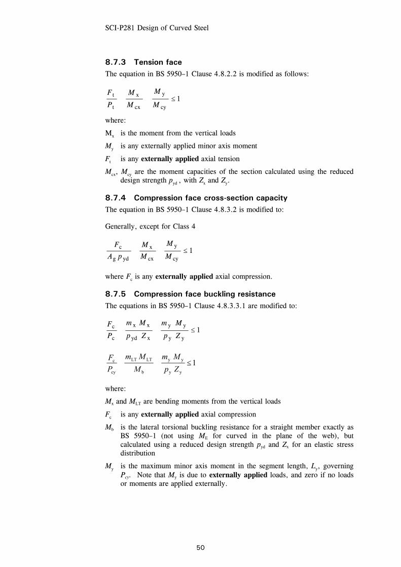
SCI-P281 Design of Curved Steel
50
8.7.3 Tension face The equation in BS 5950–1 Clause 4.8.2.2 is modified as follows:
1cy
y
cx
x
t
t ≤++M
M
M
M
P
F
where:
Mx is the moment from the vertical loads
My is any externally applied minor axis moment
Ft is any externally applied axial tension
Mcx, Mcy are the moment capacities of the section calculated using the reduced design strength pyd , with Zx and Zy.
8.7.4 Compression face cross-section capacity The equation in BS 5950–1 Clause 4.8.3.2 is modified to:
Generally, except for Class 4
1cy
y
cx
x
ydg
c ≤++M
M
M
M
pA
F
where Fc is any externally applied axial compression.
8.7.5 Compression face buckling resistance The equations in BS 5950–1 Clause 4.8.3.3.1 are modified to:
1yy
yy
xyd
xx
c
c ≤++Zp
Mm
Zp
Mm
P
F
1yy
yy
b
LTLT
cy
c ≤++Zp
Mm
M
Mm
PF
where:
Mx and MLT are bending moments from the vertical loads
Fc is any externally applied axial compression
Mb is the lateral torsional buckling resistance for a straight member exactly as BS 5950–1 (not using ME for curved in the plane of the web), but calculated using a reduced design strength pyd and Zx for an elastic stress distribution
My is the maximum minor axis moment in the segment length, Ly, governing Pcy. Note that My is due to externally applied loads, and zero if no loads or moments are applied externally.
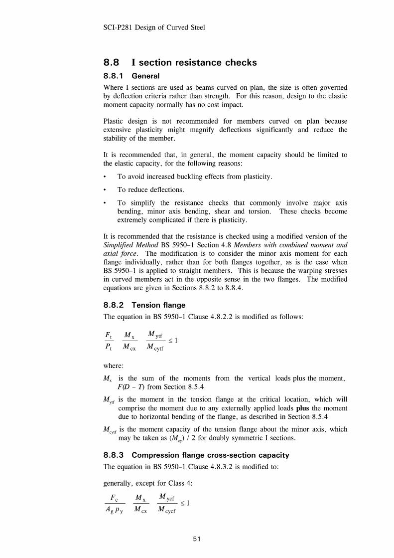
SCI-P281 Design of Curved Steel
51
8.8 I section resistance checks 8.8.1 General Where I sections are used as beams curved on plan, the size is often governed by deflection criteria rather than strength. For this reason, design to the elastic moment capacity normally has no cost impact.
Plastic design is not recommended for members curved on plan because extensive plasticity might magnify deflections significantly and reduce the stability of the member.
It is recommended that, in general, the moment capacity should be limited to the elastic capacity, for the following reasons:
• To avoid increased buckling effects from plasticity.
• To reduce deflections.
• To simplify the resistance checks that commonly involve major axis bending, minor axis bending, shear and torsion. These checks become extremely complicated if there is plasticity.
It is recommended that the resistance is checked using a modified version of the Simplified Method BS 5950–1 Section 4.8 Members with combined moment and axial force. The modification is to consider the minor axis moment for each flange individually, rather than for both flanges together, as is the case when BS 5950–1 is applied to straight members. This is because the warping stresses in curved members act in the opposite sense in the two flanges. The modified equations are given in Sections 8.8.2 to 8.8.4.
8.8.2 Tension flange The equation in BS 5950–1 Clause 4.8.2.2 is modified as follows:
1cytf
ytf
cx
x
t
t ≤++M
M
M
M
P
F
where:
Mx is the sum of the moments from the vertical loads plus the moment, F(D – T) from Section 8.5.4
Mytf is the moment in the tension flange at the critical location, which will comprise the moment due to any externally applied loads plus the moment due to horizontal bending of the flange, as described in Section 8.5.4
Mcytf is the moment capacity of the tension flange about the minor axis, which may be taken as (Mcy) / 2 for doubly symmetric I sections.
8.8.3 Compression flange cross-section capacity The equation in BS 5950–1 Clause 4.8.3.2 is modified to:
generally, except for Class 4:
1cycf
ycf
cx
x
yg
c ≤++M
M
M
M
pA
F

SCI-P281 Design of Curved Steel
52
where:
Mx is the sum of the moments from the vertical loads plus the moment, F(D – T) from Section 8.5.4
Mycf is the moment in the compression flange at the critical location, which will comprise the moment due to any externally applied loads plus the moment due to horizontal bending of the flange, as described in Section 8.5.4
Mcycf is the moment capacity of the compression flange about the minor axis, which may be taken as (Mcy) / 2 for doubly symmetric I sections.
8.8.4 Compression flange buckling resistance The equations in BS 5950–1:2000 Section 4.8.3.3.1 are modified to:
1ycfy
ycfy
xy
xx
c
c ≤++Zp
Mm
Zp
Mm
P
F
1ycfy
ycfy
b
LTLT
cy
c ≤++Zp
Mm
M
Mm
PF
where:
Mx and MLT are the sum of the bending moments from the vertical loads plus the moment due to horizontal bending of the flange, as described in Section 8.5.4
Mb is the lateral torsional resistance moment for a straight member exactly as BS 5950–1:2000 (not using ME for curved in the plane of the web)
Mycf is the maximum minor axis moment in the segment length, Ly, governing Pcy, which will comprise the moment due to any externally applied loads plus the moment due to horizontal bending of the flange, as described in Section 8.5.4
Zycf is the section modulus of the compression flange, which may be taken as (Zy) / 2 for doubly symmetric I sections.

SCI-P281 Design of Curved Steel
53
9 WORKED EXAMPLES
The following six worked examples demonstrate the design process for a number of different curved steel members. Reference is made to the previous Sections of this publication, and commentary is provided within the worked examples. The examples are not intended to demonstrate the entire design requirements. They generally demonstrate the calculation process based on only one load case, although other load cases would need to be checked in reality. In addition, the examples generally only cover ultimate limit state design, although serviceability limit state considerations of deflection will frequently be an important, if not critical, part of the design.
The table below provides a contents list for this section, showing the structural form of the member being considered and the key features demonstrated in the design.
Example number
Page number
Structural form
Key design issues
1 54 Curved roof beam
Calculation of λLT for a curved member to determine a reduced Mb, no axial load
2 64 Three-pin arch
Inclusion of out-of-plane bending stresses, and design of members subject to combined axial load and moment
3 75 Two-pin lattice arch
Modelling of curved truss members
4 81 Portal frame
Curved rafter subject to axial load and moment
5 88 Ellipse Curved I section subject to axial load and moment
6 95 Curved balcony member
I section and hollow section curved on plan. Modelling of I section to include warping effects. Inclusion of torsional stresses in design of hollow sections
All references to Standards are to BS 5950-1:2000[1].
Section properties and member resistances are taken from Design guide to BS 5950-1:2000 Volume 1, 6th Edition[6].

4
CURVED ROOF BEAMS
This example illustrates the design of curved members subject to a bendingmoment. For this example, any axial load in the member has been ignored. Theexample demonstrates the determination of a revised ALT for the calculation oflateral torsional buckling resistance. The calculations follow therecommendations given in Section 6.5.3
As the curve is relatively shallow in this example, the continuous beam was simplymodelled as a straight member to produce the shear and bending momentdiagrams. A uniformly distributed load has been used for simplicity
Having determined the shear forces and bending moments, the member capacitiesin shear and bending are checked. The major part of this example is thecalculation of the lateral torsional buckling resistance, demonstrating thatcompared with a straight member, the resistance must be reduced if compressionis on the convex side. If compression due to bending is on the concave side, theresistance is taken as that of a straight member
In this example, the out-of-plane stresses in the flanges of curved beams (seeSection 5.3) have been ignored because the governing effect is lateral torsionalbuckling, which is not affected by out-of-plane bending stresses (see Section 5.3.2)
54
The SteelCOnstructionInstitute
4__Silwood Park, Ascot, Berks SL5 7QN
Job No. BCC 842 Sheet 1 of 10 Rev
Job Title Design example no. 1
Subject Curved roof beam
Telephone: (01344) 623345Fax: (01344) 622944
CALCULATION SHEETChent Made by
SCI Checked by
TCC Date Feb 2001
ASM Date Mar 2001

55
Job No. BCC 842 Sheet 2 of 10 Rev
Job Title Design example no. 1
Subject Curved roof beam
Made by TCC Date Feb 2001
Silwood Park, Ascot, Berks SL5 7QN Telephone: (01344) 623345 Fax: (01344) 622944 CALCULATION SHEET
Client
SCI Checked by ASM Date Mar 2001
Curved roof – plan and cross section
R 17
.05
m≈
R 17
.05
m≈
sop
sop
u/s roofbeam
Continuous roof beam
1 2 3 4 5
Column
CHS ties(lateralrestraint)
Overhang1 2 3 4 5
533 UBValley beam
Roof plan - Internal bays
Cross section
1.5 m
7 m
20 m 20 m 20 m 20 m2.5 m 2.5 m
8 m
8 m
5 m 5 m 5 m 5 m10 m
533 x 210 x 122 UB - S355 Continuous roof beam

56
Job No. BCC 842 Sheet 3 of 10 Rev
Job Title Design example no. 1
Subject Curved roof beam
Made by TCC Date Feb 2001
Silwood Park, Ascot, Berks SL5 7QN Telephone: (01344) 623345 Fax: (01344) 622944 CALCULATION SHEET
Client
SCI Checked by ASM Date Mar 2001
2.5 m 20 m 20 m 20 m 20 m 2.5 m
1 2 3 4 5
105
Loading
33
138122
155
33
155138
122 105
F = 0Σ v
• Loading 13 kN/m - ULS
• Reactions (kN)
41
546 546
378
41
381
192 192
381
0.4 m 0.4 m4.315.3 m 5.2 10.9 m 3.9 3.9 10.9 m 5.2 4.3 15.3 m
2.5 m 20 m 20 m 20 m 20 m 2.5 m
Continuous roof beam
1 2 3 4 5
137 kN 294 kN 243 kN 294 kN 137 kN
8.1 11.9 10.7 9.3 9.3 10.7 11.9 8.1
• Shear force (kN)
• Bending moments (kNm)
Loading, reactions, shears and bending moments
Loading 13 kN/m – ultimate limit state
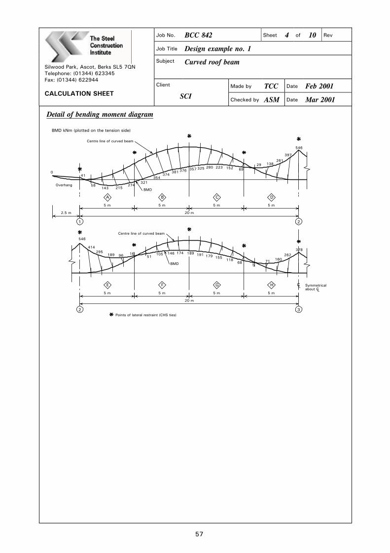
57
Job No. BCC 842 Sheet 4 of 10 Rev
Job Title Design example no. 1
Subject Curved roof beam
Made by TCC Date Feb 2001
Silwood Park, Ascot, Berks SL5 7QN Telephone: (01344) 623345 Fax: (01344) 622944 CALCULATION SHEET
Client
SCI Checked by ASM Date Mar 2001
Detail of bending moment diagram
041
58
69
143274
215321
354374
381 376 357 325 280 223 15229
261
546
397
138
BMD kNm (plotted on the tension side)
Overhang
21
A B C D
E F G H
546
414295
189 96 51105 146 189174 191 179 155
11868 71 160
37826216
5
2 3
CL Symmetrical about CL
5 m 5 m 5 m 5 m
2.5 m 20 m
5 m 5 m 5 m 5 m
20 m
Centre line of curved beam
BMD
BMD
Centre line of curved beam
Points of lateral restraint (CHS ties)

58
Job No. BCC 842 Sheet 5 of 10 Rev
Job Title Design example no. 1
Subject Curved roof beam
Made by TCC Date Feb 2001
Silwood Park, Ascot, Berks SL5 7QN Telephone: (01344) 623345 Fax: (01344) 622944 CALCULATION SHEET
Client
SCI Checked by ASM Date Mar 2001
Design – try 533 × 210 × 122 UB – S355
Section properties SCI P202
T = 21.3 mm Iy = 3390 cm4
Sx = 3200 cm3 H = 2.32 dm6
J = 178 cm4 ry = 4.67 cm
Design strength
T = 21.3 mm, therefore py = 345 N/mm2 3.1.1 Table 9
Shear capacity 4.2.3
For 533 × 210 × 122 UB – S355, Pv = 1430 kN SCI P202
0.6 Pv = 0.6 × 1430 = 858 kN 4.2.5.3
Fv = 155 kN, < 858 kN, therefore low shear 4.2.5.2
Moment capacity
For 533 × 210 × 122 UB – S355, section is Class 1 plastic SCI P202
Mcx = 1100 kNm
Mmax = 546 kNm, < 1100 kNm OK
Although out-of-plane stresses do reduce Mcx, as described in Section 5.3.2, the reduction is small and will not be critical in this case, when the applied moment is so much smaller than the capacity
Lateral torsional buckling 4.3
Check beam segment A (see Sheet 4)
BMD
321 kNm
BeamR
Plotted on the tension side
A
1
R 17.05 m≈
φ
5.0 mL

Aix = 109/27.6 = 3.9
v (Table 19), with ,
17.053 x2gx17.05 = 5.075m360
= 0.5; v 0.86
Section is Class 1 (plastic) under bending
= 1.0
ALT =
= 0.878x0.86x109xi[
Given ALT = 82 and pPb
= 82
= 345 N/mm2
Table 19
Table 16
Then Mb = Pb5x = 181x3200x103106
59
= 579kNm4.3.6.4
I'The SteelConstructionhstituto
4.—.Silwood Park, Ascot, Berks SL5 7QN
Job No. BCC 842 Sheet 6 of 10 Rev
Job Title Design example no. 1
Subject Curved roof beam
Telephone: (01344) 623345Fax: (01344) 622944
CALCULATION SHEET
Client 1Made by
SCI Checked by
TCC
ASM
IDate
Date
Feb 2001
Mar 2001
1 5.0= Sin17.05
developed length of segment =
= 17.053°
Because for this part of the member, the compression due to bending is on theconcave side of the member, the lateral torsional resistance moment is simplytaken as that for a straight member
2 = LE/r = 5075 = 10946.7
u = 0.878
x = 27.6
4.3.6.7
Sd P202
Sd P202
= 181 N/mm2
SCI P202
4.3.6.9
4.3.6.5

60
Job No. BCC 842 Sheet 7 of 10 Rev
Job Title Design example no. 1
Subject Curved roof beam
Made by TCC Date Feb 2001
Silwood Park, Ascot, Berks SL5 7QN Telephone: (01344) 623345 Fax: (01344) 622944 CALCULATION SHEET
Client
SCI Checked by ASM Date Mar 2001
Equivalent uniform moment factor 4.3.6.6
The equivalent uniform moment factor m is calculated for the general case
4.3.6.6; Table 18
Beam segment AM1 = 41M2 = 80M3 = 181M4 = 261M5 = 321
BMD (kNm)
M2 M3 M4M1
41
M5
274215
143
58
321
5075 mm - curved5000 mm - straight
mLT = m = 321
26115.01815.08015.02.0
××++××++××++
mLT = 0.64, > 0.44 OK
kNm90564.0
579
m
M
LT
b ==== 4.3.6.2
905 kNm > 321 kNm, OK
Mcx = 1100 kNm, > 321 kNm OK
Section is satisfactory for segment A
When the compression due to bending is on the concave side of the member, the member may be conservatively designed as straight. When the compression is on the convex side of the member, the lateral torsional buckling resistance moment is smaller than that of the equivalent straight section and must be calculated. This is demonstrated in the next part of the example
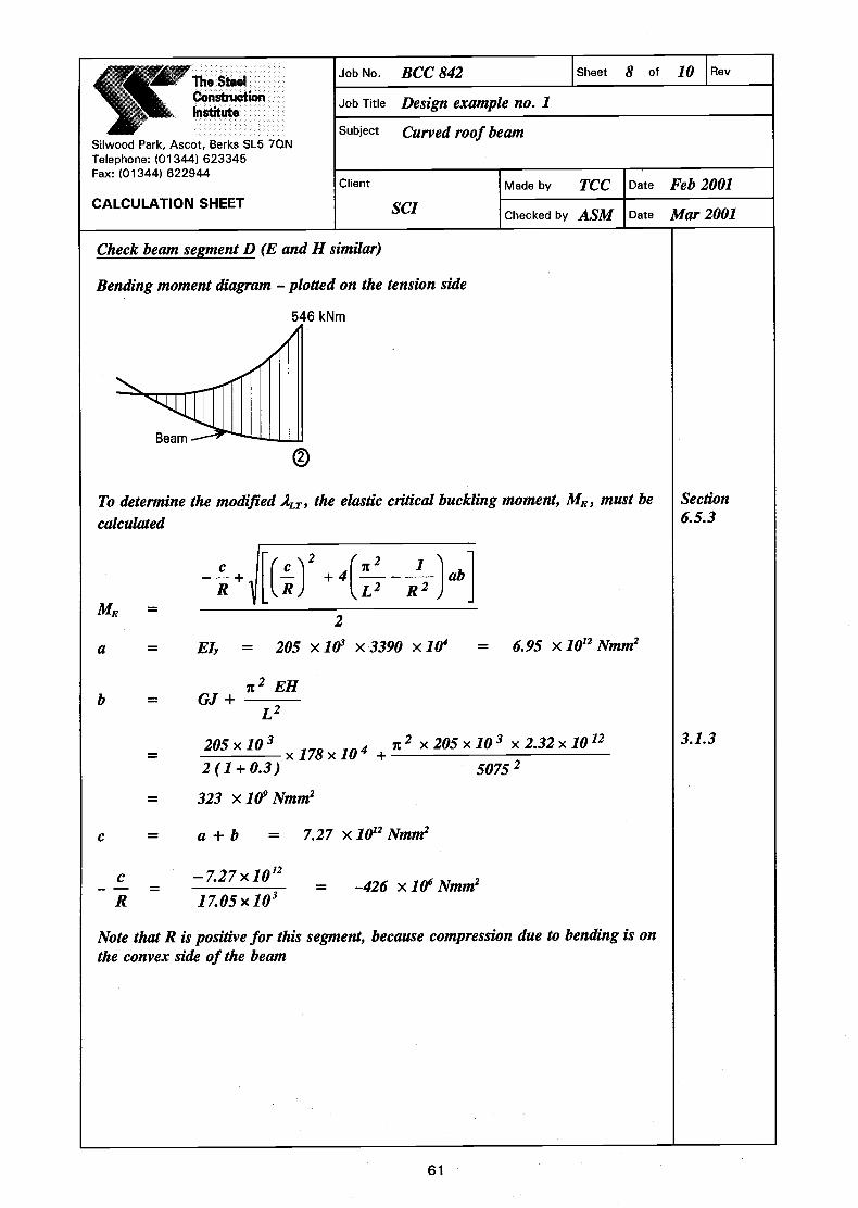
'The SteelConstructionInstitute
Silwood Park, Ascot, Berks SL5 7QN
Job No. BCC 842 Sheet 8 of 10 Rev
Job Title Design example no. 1
Subject Curved roof beam
Telephone: (01344) 623345Fax: (01344) 622944
CALCULATION SHEETClient I Made by TCC I Date Feb 2001
SCI Checked by ASM Date Mar 2001
Check beam segment D (E and H similar)
Bending moment diagram - plotted on the tension side
kNm
To determine the modified ALT, the elastic critical buckling moment, ME, must be
calculated
b
I, '2 12I(c1 litIl—ILR)
—7.27 x10¹²
17.05x10³
Note that R is positive for this segment, because compression due to bending is onthe convex side of the beam
61
3.1.3
Beam
c
R1
R2
Section6.5.3
J ab]ME 2a = EI = 205 x 101 x 3390 x 101 = 6.95 x 10¹² Nmm2
it2EH= GJ+L2
205x103 x205x10 x2.32x1012= x178x10 +2(1+0.3) 50752
= 323 xl01Nmm2
c = a + b = 7.27 xlO'2Nmm2
_________ = -426 xlO6Nmm2C
R

I
ME
—426 x106 + I(426x1o6y+41 2L50752
2
—1
')x6.95x323x1021170502)
= /Mcx It2EME Py
/iioo 2 x205x103= I xV 735 345
Pb
= 93.7 and p
= 483kNm
Equivalent uniform moment factor
5000 mm - straight
Beam segment DMl = 69M2 = 55M3 = 198M4 = 362M5 = 546
' The SteelConstructionInstitute
4—Silwood Park, Ascot, Berks SL5 7QN
Job No. BCC 842 Sheet 9 of 10 Rev
Job Title Design example no. 1
Subject Curved roof beam
Telephone: (01344) 623345Fax: (01344) 622944
CALCULATION SHEETClient 'Made by TCC IDate Feb 2001
SCI Checked by ASM Date Mar 2001
= 735 xlO'Nmm= 735 kNm
Then ALT
ALT
For ALT
93.7
= 345 N/mm2
= 151 N/mm2
Mb = PbSX— 151x3200x103
106
4.3.6.5
Table 16
4.3.6.4
k >15075 mm - curved
1< >1
546
BMD (kNm)
397
26
138
29
69Ml M2 M3 M4
274321MS
62

63
Job No. BCC 842 Sheet 10 of 10 Rev
Job Title Design example no. 1
Subject Curved roof beam
Made by TCC Date Feb 2001
Silwood Park, Ascot, Berks SL5 7QN Telephone: (01344) 623345 Fax: (01344) 622944 CALCULATION SHEET
Client
SCI Checked by ASM Date Mar 2001
mLT = 546
36215.01985.05515.02.0
×+×+×+
4.3.6.6 Table 18
= 0.5, > 0.44 OK
kNm9665.0
483
m
M
LT
b == 4.3.6.2
966 kNm, > 546 kNm OK
Mcx = 1100 kNm, > 546 kNm OK
Section is satisfactory
If a point of contraflexure lies within the length of a curved member between restraints, as shown below, a conservative approach is to assume that the whole of the convex side is in compression and take R as positive. This results in a safe lateral torsional buckling resistance moment
R
Convex side in compression
Lateral-torsional restraint
Take R as positiveConcave sidein compression

64
Job No. BCC 842 Sheet 1 of 11 Rev
Job Title Design example no. 2
Subject Three-pin arch
Made by TCC Date Feb 2001
Silwood Park, Ascot, Berks SL5 7QN Telephone: (01344) 623345 Fax: (01344) 622944 CALCULATION SHEET
Client
SCI Checked by DGB Date Mar 2001
THREE-PIN ARCH
This example demonstrates the design of curved members where the member carries significant axial load in addition to bending. The determination of in-plane effective lengths is covered, following the guidance in Section 6.4.2
In this example, the (small) effects of the out-of-plane bending stresses are taken into account when calculating the cross-sectional resistance, following the guidance in Section 5.3
This example also serves as a warning that support conditions must be considered very carefully. Supports that are flexible in reality, but modelled as fixed, produce an entirely different set of moments and forces. Realistic behaviour must be modelled. In this example, a tie between supports has been introduced to prevent spread
Although the supports are tied, the deflection of the apex has been checked following the guidance in Section 6.2.1 to confirm that first-order analysis remains appropriate

65
Job No. BCC 842 Sheet 2 of 11 Rev
Job Title Design example no. 2
Subject Three-pin arch
Made by TCC Date Feb 2001
Silwood Park, Ascot, Berks SL5 7QN Telephone: (01344) 623345 Fax: (01344) 622944 CALCULATION SHEET
Client
SCI Checked by DGB Date Mar 2001
Three-pin arch – cross section
Pin
PinPin
5.4 m 7.8 m 7.8 m 7.8 m 5.4 m
34.2 m span
17.1 m 17.1 m
Seating
sop
Flooring
Crown
LC
R = 18.6 m
LC
C of archL
Column
Ris
e
5.0
m
11.2
82 m
457 x 191 x 98 UBS275
Continuous floorbeam/tie
Stressed skin sheeting
sop
LC
LC
R =
186
00
17100 17100
11282
7318 Pin
Crown
348
348
1
3
2
4
5
67
89
1112
14 15 1617
18
3233
Pin
19 20 2122
2423
2526
2728
29
30
31*
*
**
*
*13 **
**
*
*
10
1615141312
1110
98
7
65
4
3
21
14 @ 1500 21696
18 1917
20 2122
2324
25
2627
28
29
30
3132
Member No.
Node No.
* Point of lateral andtorsional restraint
Pin
The analysis model is shown above

66
Job No. BCC 842 Sheet 3 of 11 Rev
Job Title Design example no. 2
Subject Three-pin arch
Made by TCC Date Feb 2001
Silwood Park, Ascot, Berks SL5 7QN Telephone: (01344) 623345 Fax: (01344) 622944 CALCULATION SHEET
Client
SCI Checked by DGB Date Mar 2001
172 kNm
Tie
172 kNm
162 kN 162 kN
Maximum axial force= 276 kN
231 kN 231 kN
Loading
For this example, only two load cases were considered. In load case 1, the vertical loads due to dead and imposed loads were modelled as vertical point loads applied at nodes. In the second load case, a combination of dead and wind loads has been modelled. For simplicity, all loads were applied vertically
Load case 1 Loads and bending moment diagram
Load case 2 Loads and bending moment diagram
348 kNm
366 kNm
Tie
Maximum axial force= 87 kN

67
Job No. BCC 842 Sheet 4 of 11 Rev
Job Title Design example no. 2
Subject Three-pin arch
Made by TCC Date Feb 2001
Silwood Park, Ascot, Berks SL5 7QN Telephone: (01344) 623345 Fax: (01344) 622944 CALCULATION SHEET
Client
SCI Checked by DGB Date Mar 2001
Check on adequacy of first-order analysis
Section 6.2.1 suggests that, if under ultimate limit state loading the crown of the arch drops by less than 2½% of the arch rise, a first-order analysis is satisfactory
2½% of rise = 282 mm
Actual drop from the analysis output under gravity loads (load case 1) = 97 mm
97 mm < 282 mm; first-order analysis is therefore satisfactory
Design
Try 457 × 191 × 98 UB – S275
Section properties SCI P202
B = 192.8 mm t = 11.4 mm
T = 19.6 mm r = 10.2 mm
Iy = 2350 cm4 rx = 19.1 cm
ry = 4.33 cm Zx = 1960 cm3
Sx = 2230 cm3 H = 1.18 dm6
J = 121 cm4 A = 125 cm2
Design strength
T = 19.6 mm, therefore py = 265 N/mm2 3.1.1 Table 9
Check load case 1
Shear capacity 4.2.3
For 457 × 191 × 98 UB – S275, Pv = 847 kN SCI P202
0.6 Pv = 0.6 × 847 = 508 kN
Fv (from analysis results) = 56 kN, < 508 kN, therefore low shear 4.2.5.2
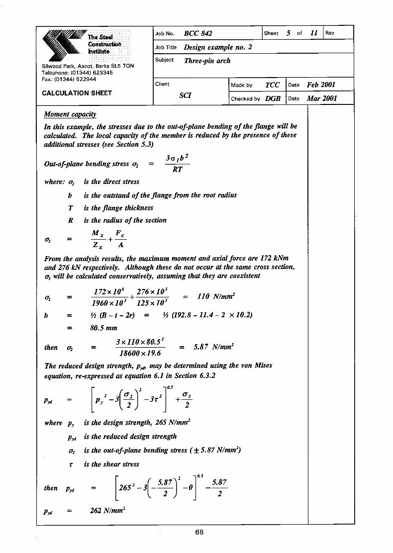
The SteelConstructionInstitute
Silwood Park, Ascot, Berks SL5 7QN
Job No. BCC 842 Sheet 5 of 11 Rev
Job Title Design example no. 2
Subject Three-pin arch
Telephone: (01344) 623345Fax: (01344) 622944
CALCULATION SHEET
Client I Made by TCC Date Feb 2001SCI Checked by DGB Date Mar 2001
Moment capacity
In this example, the stresses due to the out-of-plane bending of the flange will becalculated. The local capacity of the member is reduced by the presence of theseadditional stresses (see Section 5.3)
3a b2Out-of-plane bending stress =
RT
where: cr1 is the direct stress
b is the outstand of the flange from the root radius
T is the flange thickness
R is the radius of the section
M P= —-I-—Z, A
From the analysis results, the maximum moment and axial force are 172 kNmand 276 kN respectively. Although these do not occur at the same cross section,c will be calculated conservatively, assuming that they are coexistent
172x106 276x103= + = 110 N/mm21960x103 125x102
b = '/2 (B—t—2r) = '/2 (192.8—11.4—2 xlO.2)
= 80.5 mm
3 110x805then o = • = 5.87 N/mm2
18600 x 19.6
The reduced design strength, p, may be determined using the von Misesequation, re-expressed as equation 6.1 in Section 6.3.2
, '..2 0.5
2 (°2 i 2 02P,a = p,, _3_j
—3r +—
where p, is the design strength, 265 N/mm2
p is the reduced design strength
q is the out-of-plane bending stress (± 5.87 N/mm2)
z is the shear stress
then Pyd =[2652 3 5.87)2 _0] —
5.87
t'yd= 262 N/mm2
68

The SteelConstructionInstitute
Silwood Park, Ascot, Berks SL5 7QN
Job No. BCC 842 Sheet 6 of 11 Rev
Job Title Design example no. 2
Subject Three-pin archTelephone: (01344) 623345Fax: (01344) 622944
CALCULATION SHEETClient i Made by TCC I Date Feb 2001
SCI Checked by DGB Date Mar 2001
Note that the out-of-plane bending stress is taken as negative, being the mostconservative approach. Note also that the shear stress has been taken as zero.This is because the shear stress is small, and also because the approach taken isconservative. An enhancement to the yield stress is available if the out-of-planebending stress is taken as positive, which has also been ignored
Reduced bending capacity
SCI P202
4.2.5.2
Cross-sectional capacity under axial load and moment
Note the substitution of the reduced bending stress, Pyd, in the following clause
F M M 4.8.3.2+ +
AgPyd
276x103 171 = 0.38,<1OK125x102x262 585
Member buckling resistance 4.8.3.3
Out-of-plane bending stresses do not affect the lateral buckling resistance so p,will be taken as 265 N/mm2 in the lateral buckling (Pu) and lateral torsionalbuckling (Mb) checks. The reduced design stress of 262 N/mm2 will be used inthe major axis buckling terms (M and P)
Two relationships must be satisfied. Firstly:
F mM mM÷PC PyZx
P is the smaller of P and Pt,,. Lateral restraints are provided at 3 m centres inthe minor axis. The maximum length is from node 1 to node 4 (see Sheet 2).Length from node 1 to node 4 = 2 x 1500 + 348 3348 mm
ForPg, = L = 3348 mm
A = 3348/43.3
pt,, = 182 N/mm2
Section is at least Class 2 compact
zt = Pyd S =262x2232x103
106= 585kNm
Pcy= Ag pcy =
4.8.3.3.1
4.7.3
4.7.2
4.7.5Table 23Table 24(3)
4.7.4(a)
= 77.3
125 x 102 x 182 x i0 = 2275 kN
69

The SteelCOnstRictionInstitute
Silwood Park, Ascot, Berks SL5 7QN
Job No. BCC 842 Sheet 7 of 11 Rev
Job Title Design example no. 2
Subject Three-pin archTelephone: (01344) 623345Fax: (01344) 622944
CALCULATION SHEETClient I Made by TCC I Date Feb 2001
SCI Checked by DGB Date Mar 2001
For
LE, the effective length in plane, is determined from Figure 6.13
24950A = ____ = 131
191
Pcx = 102 N/mm2
—l
0.33, therefore /3 = 1.15
1.15 X s (developed length to crown)
1.15 x 21696 = 24950 mm
P = Ag p = 125 X 102 x 102 x i0 = 1275 kN= minimum (2275, 1275) = 1275 kN
Equivalent uniform moment factor
4.8.3.3.4,Table 26
L
11.2 82f/L= =34.2
Therefore, LE =
LE =
4.7.2
Table 23Table 24(2)
4.7.4(a)
The equivalent uniform moment factor m is calculated for the general case
L= 21696 mm
M1Mmax
M2 M3 M4 M5
The bending moment diagram on the developed length to the crown is shown above
M1=0, M2=l48kNm, M3=l34kNm, M4=26.4kNm, M5=0
Mmt = 171 kNm, M24 = 171 kNm
70

0.1 x 148 + 0.6 x 134 + 0.1 x 26.40.2 + = 0.77
0.8M24but not less than MTherefore m = 0.8
= 0.8x17108171
:+ mMPC PYIIZX
276 0.8x171x106= ÷1275 262x1957x103
= 0.48, <1.0 OK4.8.3.3.1
Note the use of the reduced design strength in the above equation
The second relationship to be satisfied is:
Lateral torsional buckling can only occur between the restraints at 3 m centres.The maximum moment is 171 kNm and is only slightly less at the adjacentrestraints. A uniform moment is therefore assumed
mLT = 1.0 (/3 = 1.0)
Because the bending causes compression on the concave side, the resistance tolateral torsional buckling is taken as that for a straight member
A = LE/rY
u = 0.881
x = 25.7
69 / 25.7
v (Table 19), with , = 0.5; v = 0.92
Section is at least Class 2 (compact)
= 1.0
ALT = uvA[l= 0.881 x 0.92 x 69 x fi = 56
Given ALT = 56 and p 265 N/mm2
Pb = 217 N/mm2
The SteelConstructionInstitute
Siwood Park, Ascot, Berks SL5 7QN
Job No. BCC 842 Sheet 8 of 11 Rev
Job Title Design exwnple no. 2
Subject Three-pin arch
Telephone: (01344) 623345Fax: (01344) 622944
CALCULATION SHEETClient Made by
SCIIChecked by
TCC I Date Feb 2001
DGB Date Mar 2001
Therefore, m 171
F mLTMLTPCy M
m M,+
Pyzy
69
Aix =
300043.3
= 2.7
4.8.3.3.1
Table 18
4.3.6.7
SCI P202
SCI P202
Table 19
SCI P202
4.3.6.9
4.3.6.5
Mb = Pb5x217x2232x103
106= 484 kNm
71

72
Job No. BCC 842 Sheet 9 of 11 Rev
Job Title Design example no. 2
Subject Three-pin arch
Made by TCC Date Feb 2001
Silwood Park, Ascot, Berks SL5 7QN Telephone: (01344) 623345 Fax: (01344) 622944 CALCULATION SHEET
Client
SCI Checked by DGB Date Mar 2001
Then
0.1,47.0484
1710.1
2275
276
M
Mm
P
F
b
LTLT
cy
c <<==××
++==++ OK
Member has adequate buckling resistance
Note that the analysis assumes rigid supports. The extension of the tie between supports was checked and found to be negligible. The assumption of rigid supports was therefore considered to be reasonable
Check load case 2
The second load case produces compression on the convex side of the member, reducing the resistance to lateral torsional buckling. The following calculations demonstrate the determination of a reduced Mb , based on a reduced 88LT
The maximum moment (349 kNm) and axial load (87 kN) will again be assumed to be coexistent
Mcx (see Sheet 6) = 585 kNm, > 349 kNm OK
Cross-section capacity 4.8.2.3
1M
M
M
M
pA
F
cy
y
cx
x
ydg
c <<++++
Re-calculating pyd for this load-case (as demonstrated on Sheet 5) gives pyd = 260 N/mm2
585
349
26010125
10872
3
++××××
×× = 0.62, < 1 OK
Buckling resistance
Pc = 1275 kN (Sheet 7)
For the equivalent uniform moment factor mx
4.8.3.3.4 Table 26
M1 = 0, M2 = 182 kNm, M3 = 339 kNm, M4 = 381 kNm, M5 = 0
Mmax = 348 kNm, M24 = 348 kNm
mx = 0.2 +348
3181.03396.01821.0 ××++××++×× = 0.93
but not less than 8.0348
3488.0
M
M8.0
max
24 ==××
==
mx = 0.93
Then xy
xx
c
c
Zp
Mm
P
F++ =
3
6
101957260
1034893.0
1275
87
××××××××
++ = 0.70, < 1 OK 4.8.3.3.1

The SteelConstruction
,_L Institute4__T
Silwood Park, Ascot, Berks SL5 7QN
Job No. BCC 842 Sheet 10 of 11 Rev
Job Title Design example no. 2
Subject Three-pin arch
Telephone: (01344) 623345Fax: (01344) 622944
CALCULATION SHEET
Client Made by
sci Checked by
TCC Date Feb 2001
DGB Date Mar 2001
The second relationship to be satisfied is:
FmLTMLT 4.8.3.3.1
Mb J)yZy
In similar fashion to the first load case, a uniform moment between restraints has Table 18been assumed, and mLT = 1
The lateral torsional buckling resistance moment is calculated using a revisedequivalent slenderness ALT
2LT is calculated from the elastic critical buckling moment ME (see Section 6.5.3)
a = EI 205 x1U3 x2437 x104 = 5.00 xlO'2Nmm2
b = GJ+EHL2
E 3.1.3G = ,wherev=0.3
2(1+v)205x103 x121x104 t2 x205x103 xl.18x1012
b = +2(1÷0.3) 30002
= 361 xlO9Nmm2
c = a + b = 5 x10¹² + 361 x109 = 5.36 xlO'2Nmm2
C = —5.36x10'2 = —288x106R 18600
Note that R is positive for this segment, because the compression due to bending ison the convex side of the member
Then ME =
+ I(28sx1o6Y+41 2 —
1 ')x5.oox36lxlo2lL30002 186002)
2
ME = 1.27 xlO9Nmm = 1270 kNm
= x7t2E
MEPY
M,, = 592 kNm SCI P202
/592 ,r2x205x103I x = 59.71270 265
73

The SteelConstructionInstitute
Sliwood Park, Ascot, Berks SL5 7QN
Job No. BCC 842 Sheet 11 of 11 Rev
Job Tit'e Design example no. 2
Subject Three-pin arch
Telephone: (01344) 623345Fax: (01344) 622944
CALCULATION SHEETClient Made by
SCI Checked by
TCC
DGB
I Date
Date
Feb 2001
Mar 2001
87 1.0x348=2275 462
The hogging region also requires checking in similar fashion to load case 1
In summary:
Bending capacity
= 585 kNm, > 366 kNm OK
Capacity under axial load and moment
F M+AgPyd
87x103 366= +—125x102x260 585
= 0.65, <1 OK
871275
0.8x366x106260x1957x103
= 0.64,<1OK
F mLTMLTand —+Pc M,
87 1.0x366= +1275 484
= 0.82,<1OK
Section is satisfactory
74
Given ALT = 59.7 and p = 265 N/mm2, Pb = 207 N/mm2
207x2232x103Mb = PbSX =
Then !L+mLTMLT"cy Mb
106= 462 kNm
= 0.8,<1OK
4.6.3.5Table 16
4.8.3.3.1
4.2.5.2
4.8.3.2
4.8.3.3Buckling resistance
m (similar calculation to page 13) =
F mMThen —+'c OyZ3
0.8

75
Job No. BCC 842 Sheet 1 of 6 Rev
Job Title Design example no. 3
Subject Two-pin lattice arch
Made by TCC Date Mar 2001
Silwood Park, Ascot, Berks SL5 7QN Telephone: (01344) 623345 Fax: (01344) 622944 CALCULATION SHEET
Client
SCI Checked by ASM Date Apr 2001
TWO-PIN LATTICE ARCH
This relatively simple example demonstrates the modelling of curved members by using straight elements
The long span truss in this example has curved chords of 55 m radius. Both chords have the same radius. A more usual solution would be to have a common setting out point, with different radii for each chord, and internal members set out with respect to the radial directions
The abutments were initially modelled as rigid. As this was an unrealistic assumption, a horizontal spring was introduced at one support. The spring stiffness used was determined by an iterative process until a target movement of 20 mm was realised. This movement was considered to be compatible with the abutment construction and foundation. The importance of realistic modelling of the supports cannot be over-emphasised, as the forces within the truss members change considerably depending on the support stiffness
At the end of the example, alternative approaches to allow for the effects of curvature not modelled in the analysis are considered
All members are hot-finished hollow sections. Note that BS 5950–1:2000 also covers cold-formed hollow sections

76
Job No. BCC 842 Sheet 2 of 6 Rev
Job Title Design example no. 3
Subject Two-pin lattice arch
Made by TCC Date Mar 2001
Silwood Park, Ascot, Berks SL5 7QN Telephone: (01344) 623345 Fax: (01344) 622944 CALCULATION SHEET
Client
SCI Checked by ASM Date Apr 2001
Exhi
bitio
n ce
ntre
FFL
14
13
12
11
10
98
54
215
16
17
18
19
20
21
22
23
24
37
125
6
Bay
cen
tres
= 9
.0 m
*
Top
& b
otto
m c
hord
219.0
Ø x
6.3
CH
S -
S275
Inte
rnal
'di
agon
als'
76.2
Ø x
4.0
CH
S -
S275
Inte
rnal
' v
ertica
ls'
60.3
Ø x
4.0
CH
S -
S275
Pin
**
**
*
R = 55 m
R = 55 m
Loca
tion
s of
late
ral r
estr
aint
to
bott
om b
oom
2400
2400
2400
2400
2400
2400
2400
2400
2400
2400
2400
2400
2400
2400
2400
2400
2400
2400
2400
2400
1816
1000
1000
2400
2400
54495 m
m s
pan
2248 5752
Cla
ddin
g lin
e
2679
4600
921
Rei
nfor
ced
conc
rete
abut
men
t
4600
1784
2000
29216
25279
Col
d ro
lled
purli
ns
Rei
nfor
ced
conc
rete
abut
men
t
Pin
General arrangement

77
Job No. BCC 842 Sheet 3 of 6 Rev
Job Title Design example no. 3
Subject Two-pin lattice arch
Made by TCC Date Mar 2001
Silwood Park, Ascot, Berks SL5 7QN Telephone: (01344) 623345 Fax: (01344) 622944 CALCULATION SHEET
Client
SCI Checked by ASM Date Apr 2001
Member numbers
Joint numbers
Analysis results
With both chords continuous, all internals pinned, and a spring support, the maximum forces in the chords were:
Member 1 621 kN (compression) 2 kN shear 7 kNm bending moment
length from analysis model = 3264 mm (straight)
The following calculations demonstrate the checks on member 1. Other members would need to be checked following a similar process, notably member 22, which has a reduced axial load but an increased length compared with member 1
1
23
45
67
9 118
10 12 14 1613 1517 18
1920
2122
23
28 27
3334
3231
3029
43
44
45
42414039
3837
36
3546
4748
4950
51 52 53 54 55 56 57 58 59 60 6162 63
6465
24
2526
1
23
4
67 8
9 10 11 12 14 15 16 17 18 1920
21
23
225
13
34
33
3231
30 29 28 2726
25
24
2400 2400
Normal
Top chord
Bottomchord
55 m55 m

78
Job No. BCC 842 Sheet 4 of 6 Rev
Job Title Design example no. 3
Subject Two-pin lattice arch
Made by TCC Date Mar 2001
Silwood Park, Ascot, Berks SL5 7QN Telephone: (01344) 623345 Fax: (01344) 622944 CALCULATION SHEET
Client
SCI Checked by ASM Date Apr 2001
Over a length of 3264 mm, the maximum eccentricity between the true curve and the assumed straight element is 25 mm
As a conservative but simple approach, the moment due to the eccentricity from the straight analysis element will be added to the moment in the member
Additional moment due to eccentricity = 621 × 0.025 = 15.5 kNm
Total moment = 15.5 + 7 = 22.5 kNm
Check chord section
219.1 × 6.3 CHS – S275, therefore py = 275 N/mm2 Table 9
A = 42.1 cm2 Z = 218 cm3 D / t = 34.8 SCI P202
r = 7.53 cm S = 285 cm3
Cross-section capacity
Section is Class 1 (plastic) Table 12
Ag py = kN115810
101.422753
2
==××××
4.8.3.2
Mcx = pyS = kNm4.7810
102852756
3
=××
4.2.5.2
Then cy
y
cx
x
yg
cMM
MM
pAF
++ 4.8.3.2
= 0.1,82.04.78
5.22
1158
621<=+ OK
Lateral torsional buckling
Circular hollow sections do not need to be checked for lateral torsional buckling 4.3.6.1
e = 25 mm
L = 3264 mm
L = 3265 mmTop chord

Buckling resistance
ForPandP,LE = 3264 mm (from analysis model)
= 1082 kN
Table 23Table 24(1)
Taking MLT and M as 1.0 for simplicity
Note that Mb = Mfor CHS
Then + mLTMLTMb
621 1.0x22.5x106= +1082 275x285x103
Section satisfactory
Modelling issues
Modelling with chords as straight elements, and continuous, produces areasonable estimate of the bending moment in the member, particularly at largeradii
As an alternative, the truss was re-modelled with additional nodes introduced mid-way along each chord element
79
The SteelConstructionInstitute
Silwood Park, Ascot, Berks SL5 7QN
Job No. BCC 842 Sheet 5 of 6 Rev
Job Title Design example no. 3
Subject Two-pin lattice arch
Telephone: (01344) 62334Fax: (01344) 622944
CALCULATION SHEET
Client I Made by TCC Date Mar 2001SCI Checked by ASM Date Apr 2001
4.8.3.3.1
3264A = LE/r = = 43
75.3
Given A = 43 and p = 275 N/mm2, PC = 257 N/mm2
Therefore
257x42.1x102PC
= PCX= =
F mMPC PyZx
621 1.0x22.5x106= +1082 275x218x103
= 0.95,<1 OK
4.8.3.3.1
4.3.6.1
4.8.3.3.1
= 0.86, <1 OK

80
Job No. BCC 842 Sheet 6 of 6 Rev
Job Title Design example no. 3
Subject Two-pin lattice arch
Made by TCC Date Mar 2001
Silwood Park, Ascot, Berks SL5 7QN Telephone: (01344) 623345 Fax: (01344) 622944 CALCULATION SHEET
Client
SCI Checked by ASM Date Apr 2001
The bending moments along the critical chord (nodes 1 to 3) are shown below
4
2
1
3
3.5
3.4
5.8
15.0
0.5
In this case the axial load has reduced to 615 kN but the moment increased to 15 kNm
In this case, the equivalent uniform moment factor, m, may be determined from Table 26 to be 0.42
Hence ,67.010218275
101542.0
1082
6153
6
==××××××××
++ < 1 OK 4.8.3.3.1
If the truss had been modelled as pinned throughout, the axial force in the member would be 625 kN
Multiplying this force by the offset gives a moment of
625 × 0.025 = 16 kNm at mid-element
Substituting this combination in the buckling check, with an equivalent uniform moment factor, m, of 1.0 results in a unity value of 0.84
This example demonstrates that increasing refinement (additional nodes and use of the equivalent uniform moment factor) can be used to obtain a more economic section. For most purposes, however, a simple analysis that takes account of the eccentricity of the real structure from the straight-line analysis model will suffice

81
Job No. BCC 842 Sheet 1 of 7 Rev
Job Title Design example no. 4
Subject Portal frame
Made by NK Date Apr 2001
Silwood Park, Ascot, Berks SL5 7QN Telephone: (01344) 623345 Fax: (01344) 622944 CALCULATION SHEET
Client
SCI Checked by DGB Date May 2001
PORTAL FRAME
This example demonstrates the significant features of the design of a portal with a curved rafter. Although only curved to a moderate radius, the frame has been analysed elastically. A subsequent plastic analysis of a similar frame with straight members produced the same member sizes and, thus, in this instance, no penalty results from either the elastic analysis or the use of curved members
Checks that differ from the usual checks of straight members are included in this example. Where the curvature of the member gives beneficial effects (i.e. when the member resistances are conservatively taken as those of a straight member), no example calculations are included. The reader is referred to BS 5950-1[1] and other publications[7] covering the design of portal frames, where the details of the checks on straight members are illustrated

82
Job No. BCC 842 Sheet 2 of 7 Rev
Job Title Design example no. 4
Subject Portal frame
Made by NK Date Apr 2001
Silwood Park, Ascot, Berks SL5 7QN Telephone: (01344) 623345 Fax: (01344) 622944 CALCULATION SHEET
Client
SCI Checked by DGB Date May 2001
Geometry
The frame has the dimensions as detailed below, with purlins providing lateral restraint at 1.656 m centres
4300
200
7450
36 m span
LC
R = 40 m
Pin bases
UB457 x 191 x 67 curved rafter
UB610 x 229 x 101column
Procedure
In common with all portal frames, the following steps must be followed: 5.5.4
• determination of initial sizes
• check of in-plane stability
• check of member resistances
Initial sizes
Following an initial analysis, the members shown in the general arrangement were chosen In-plane stability
The portal geometry must be checked to ensure the (simple) sway-check method may be used to verify that the portal is stable in plane
5 × h = 5 × 7.450 = 37.25 m
span, L = 36 m, < 37.25 m OK
rise hr = 4.25 m (based on centre-line dimensions)
0.25 × span = 0.25 × 36 = 9 m, > 4.25 m OK
The sway-check method may therefore be used
The notional horizontal loads are taken as 0.5% of the base reaction, and applied horizontally in the same direction at the top of each column

This load case was analysed, and the maximum horizontal deflection at columntop was found to be 4.6 mm
Analysis
= 7450/1000 —
The rafter was modelled with 23 straight elements. Under a vertical UDL and thenotional horizontal loads, the bending moment diagram is as shown below
The checks on the columns are no different from those in portal frames with allstraight members, and are not included in this example.
Between A—B, and C-D, the curved rafter is in hogging. The bending momentproduces compression on the concave side of member, and the design resistance isat least that of a straight member. The regions A-B and C-D should be checkedas if straight, with full consideration of restraint positions etc.
Between points B and C, the curved rafter is in sagging. The bending momentproduces compression on the convex side of the member, reducing its capacity.The following checks illustrate how the member in this zone should be checked.
From the analysis, the maximum forces between B and C (assumed to coexist)were:
M = 319.3 kNm
= 113.2kN
9OkN
The SteelConstructionInstitute
Silwood Park, Ascot, Berks SL5 7QN
Job No. BCC 842 Sheet 3 of 7 Rev
Job Title Design example no. 4
Subject Portal frameTelephone: (01344) 623345Fax: (01344) 622944
CALCULATION SHEETClient I Made by NK I Date Apr 2001
SCI Checked by DGB Date May 2001
Limit h / 1000
4.6 < 7.45, therefore A, = 1.0
7.45 mm
5.5.4.2.2
5.5.1
A
Design
83

x191 x67UB S275
= 453.4 mm= 189.9 mm
= 8.5mm
= 12.7 mm
= 10.2 mm
= 85.5 cm2
= 37.1 cm4
Reduced design strength
= 1300 cm3
= 153 cm3
= 1470 cm3
= 1450 cm4
= 4.12 cm
= 18.5 cm
= 0.705 dm6
M F 319.3x10⁶ 113.2x103= + =Z, A 1300x103 85.5x102
= 2752 _3(1 9.9Pyd
L
0.5
2)] 2 = 270 N/mm2
84
Section6.3.2
The SteelCOnstructionInstitute
Silwood Park, Ascot, Berks SL5 7QN
Job No. BCC 842 Sheet 4 of 7 Rev
Job Title Design example no. 4
Subject PortaiframeTelephone: (01344) 623345Fax: (01344) 622944
CALCULATION SHEET
Client I Made by NK I Date Apr 2001SCI Checked by DGB Date May 2001
Rafter section properties
457
D
B
t
T
rA
J
zx
zy
SI
Iy
rr1
H
SCI P202
Section 5.3
Section 5.3
259 N/mm2
The curvature induces bending stresses in the flanges, which combine with theaxial stress to reduce the effective yield stress ofthe section. The reduced designstrength, Pyd, is calculated following the procedure given in Section 6.3.2:
Calculate the out-of-plane bending stress:
3cr,b202 =
RT
0i
b = '/2 (B-t—2r) = '/2 (189.9-8.5-2 xlO.2) = 80.5mm
3x259x80.52 2= = 9.9 N/mm40x103 x12.7
Calculate the reduced design strength from equation 6.1
f 0.5
2 (021 2Pyd = p 3t
(shear stress, r, is ignored)

The SteelConstructionInstitute
Silwood Park, Ascot, Berks SL5 7QN
Job No. BCC 842 Sheet 5 of 7 Rev
Job Title Design example no. 4
Subject Portal frameTelephone: (01344) 623345Fax: (01344) 622944
CALCULATION SHEET
Client I Made by NK I Date Apr 2001SCI Checked by DGB Date May 2001
Calculate effective slenderness
ALT = [M r2EVME P
If \2C ((C——+ II—RR
3.52x10¹² fr'3.s2x1o12"2 ( 2+41—
40x103 40x10 J 16562 (4OxlO3)2J2
85
Cross-section capacity
Calculated in accordance with BS 5950—1 Clause 4.8.3.2 but substituting PydforpThe relationship to be satisfied is:
F M M+ +AgPyd
Section is at least Class 2 (compact), and M = pS
Then:113.2x10³ + 319.3x10⁶ +0 = 0.85, < 1 OK
85.5x102 x270 1470x103 x270
Lateral torsional buckling
Lateral torsional buckling between purlin positions must be checked, because thebending moment produces compression on the convex side of the member, and theresistance of the member is reduced
(2—41 lab
LL2 R2)ME =2
a = EI = 205 x1U3 x1450 x104 = 2.97 xlO'2Nmm2
ir2EHb = GJ-i-
L2
205x103 x37.1x104 r2 x205x103 xO.705x1012___________________ = 5.49x10'1Nmm2
(1.656 x 10³)2
2.97 x 10 + 5.49 x 10" = 3.52 x 10¹² Nmm2
2(1+ 0.3)
C = a+b =
Therefore, ME =

86
Job No. BCC 842 Sheet 6 of 7 Rev
Job Title Design example no. 4
Subject Portal frame
Made by NK Date Apr 2001
Silwood Park, Ascot, Berks SL5 7QN Telephone: (01344) 623345 Fax: (01344) 622944 CALCULATION SHEET
Client
SCI Checked by DGB Date May 2001
= 2.38 × 10⁹ Nmm
ME = 2380 kNm
Then: 4.35270
10205
102380
101470270 32
6
3
LT ==××××
××××
××××==
ππλλ
The modified effective slenderness may now be used to calculate the buckling resistance of the member
Lateral torsional buckling resistance
To check lateral torsional buckling, Clause 5.5.2 directs the designer to Clause 4.8.3.3
5.5.2
Clause 4.8.3.3.2(a) contains two equations for members with moments about the major axis only For major axis in-plane buckling:
4.8.3.3.2(a)
1P
F5.01
M
Mm
P
F
cx
c
cx
xx
cx
c ≤≤
++++
and for out-of-plane buckling:
1M
Mm
P
F
b
LTLT
cy
c ≤≤++
The first of these is an in-plane check. In-plane stability has already been checked by the sway stability provisions (Clause 5.5.4) so, in general, only the second relationship (covering out-of-plane effects) need be satisfied
For Pcx , Le (eaves to apex) = 18.5 m approximately. Assuming a straight member without haunches:
yλλ = 2.41
1656 = 40, therefore pcy = 245 N/mm2
Table 24(b)
Pcy = Ag pcy = 8550 × 245 × 10–3 = 2095 kN
Over a length between purlins, the moment will be taken as constant,
therefore, mLT = 1.0 Table 18
with λλLT = 35, and py = 275 N/mm2, pb = 273 N/mm2 Table 16
Mb = pb Sx = 273 × 1470 × 10–3 = 401 kNm

87
Job No. BCC 842 Sheet 7 of 7 Rev
Job Title Design example no. 4
Subject Portal frame
Made by NK Date Apr 2001
Silwood Park, Ascot, Berks SL5 7QN Telephone: (01344) 623345 Fax: (01344) 622944 CALCULATION SHEET
Client
SCI Checked by DGB Date May 2001
Then b
LTLT
cy
c
M
Mm
P
F++
= 85.010401
103.3190.1
102095
102.1136
6
3
3
==××
××××++
××××
, <1 OK
Section is satisfactory between B and C. Rafter sections A–B and C–D, and the columns, must be checked as straight members
Reversal load case In the reversal load case shown below, the zone B–C will be checked as a straight member, between restraints (usually bracing from the purlins to the bottom flange). In zones A–B and C–D, the moment produces compression on the convex side of the member, reducing the capacity of the member
AB C
D
No guidance is offered on a procedure to check a curved tapered element. It is anticipated that for orthodox frames, inspection will show that the haunch is stable between restraint positions (typically at both ends of the haunch) under the much reduced reversal moment compared with the gravity load case. If doubt exists, the capacity of the tapered section should be calculated as if straight, then an appropriate reduction made. The reduction in resistance may be taken as the same proportion as for the un-haunched rafter
The section sizes used for the frame in this example are the same as those that would be used in a frame with straight rafters, illustrating the fact that curved sections need not be less economical than straight sections. While the maximum unity factor in the resistance checks is only 0.85, it is unlikely that a smaller rafter could be chosen, as other parts of the rafter are expected to be critical. The example has only checked the portion of the rafter subject to a sagging moment. The hogging regions, and columns, must be checked

88
Job No. BCC 842 Sheet 1 of 7 Rev
Job Title Design example no. 5
Subject Ellipse
Made by NK Date Apr 2001
Silwood Park, Ascot, Berks SL5 7QN Telephone: (01344) 623345 Fax: (01344) 622944 CALCULATION SHEET
Client
SCI Checked by DGB Date May 2001
ELLIPSE
This example demonstrates the design of curved steel members used as elliptical shaped supports to the cladding around pedestrian walkways and similar structures
With such a relatively small frame, the example demonstrates that either the serviceability limit state or aesthetic requirements are likely to be critical when choosing a steel section. Nevertheless, this example demonstrates the ultimate limit state design procedure to be followed, which will become critical for larger, more heavily loaded frames
In practice, for the size of frame in this example, a hollow section would probably be used
A preliminary analysis showed that a suitable hollow section would not need to be checked for lateral torsional buckling, so a small I section was chosen to demonstrate the calculation process

89
Job No. BCC 842 Sheet 2 of 7 Rev
Job Title Design example no. 5
Subject Ellipse
Made by NK Date Apr 2001
Silwood Park, Ascot, Berks SL5 7QN Telephone: (01344) 623345 Fax: (01344) 622944 CALCULATION SHEET
Client
SCI Checked by DGB Date May 2001
Geometry
B C
A D Pinnedbase
R = 1.64
R =
2.5
0
R = 1.64
3.00
4.33
3.10
0.70
The ellipse is constructed as a three-point circle giving the shape of an ellipse while eliminating the constantly changing radius of a true ellipse. In practice, this may be more economical to roll than a constantly changing radius
Purlins provide lateral restraint at 1 m centres around the hoop perimeter
Analysis
The analysis model and first load case are shown above. Point loads were applied at purlin positions; the model had additional nodes midway between purlin positions
It should be noted that the other load cases should be checked

90
Job No. BCC 842 Sheet 3 of 7 Rev
Job Title Design example no. 5
Subject Ellipse
Made by NK Date Apr 2001
Silwood Park, Ascot, Berks SL5 7QN Telephone: (01344) 623345 Fax: (01344) 622944 CALCULATION SHEET
Client
SCI Checked by DGB Date May 2001
The bending moment diagram resulting from an elastic analysis is shown below
A D
= Node used in analysis= Purlin position
B C
*
* *
* *
*
*
*
*
*
*
Between A–B and C–D, the bending produces compression on the concave side of the member. In these zones, the member should be checked as if it were straight
Between B and C, the bending produces compression on the convex side of the member, which reduces its resistance to lateral torsional buckling. The following calculations illustrate the design checks in this region
Member between B and C (compression on convex face)
Design – try 152 × 89 × 16 UB, S275
D = 152.4 mm Zx = 109 cm3
B = 88.7 mm Zy = 20.2 cm3
t = 4.5 mm Sx = 123 cm3
T = 7.7 mm Iy = 89.8 cm4
r = 7.6 mm rx = 6.41 cm
A = 20.3 cm2 ry = 2.10 cm
J = 3.56 cm4 H = 0.0047 dm6

91
Job No. BCC 842 Sheet 4 of 7 Rev
Job Title Design example no. 5
Subject Ellipse
Made by NK Date Apr 2001
Silwood Park, Ascot, Berks SL5 7QN Telephone: (01344) 623345 Fax: (01344) 622944 CALCULATION SHEET
Client
SCI Checked by DGB Date May 2001
Between B and C, the maximum values of moment, axial compression and shear (assumed coincident) were:
Mx = 11.4 kNm
Fc = 1.6 kN
Fv = 5 kN
The out-of-plane bending stress is calculated, and used to determine a reduced design stress following the procedure in Section 6.3.2
Out-of-plane bending stress, RT
b3 21
2
σσσσ ==
Section 5.5
Direct stress, 2
3
3
6
103.20
106.1
10109
104.11
A
F
Z
M
××
+××
=+= c
x
x1σ = 105 N/mm2
(( )) 5.34)6.725.47.88(r2tBb 21
21 ==××−−−−==−−−−== mm
5.197.72500
5.341053 2
==××××××
==2σσ N/mm2
Calculate the reduced design strength from equation 6.1 Section 6.3.2
pyd = 2
32
3p 2
5.0
2
2
22y
σσττ
σσ−−
−−
−−
pyd = 2
5.19
2
5.193275
5.022 −−
−−
pyd = 265 N/mm2

92
Job No. BCC 842 Sheet 5 of 7 Rev
Job Title Design example no. 5
Subject Ellipse
Made by NK Date Apr 2001
Silwood Park, Ascot, Berks SL5 7QN Telephone: (01344) 623345 Fax: (01344) 622944 CALCULATION SHEET
Client
SCI Checked by DGB Date May 2001
Cross-section capacity
Section is not slender SCI P202
The relationship to be satisfied is:
1M
M
M
M
pA
F
cy
y
cx
x
ydg
c ≤≤++++ 4.8.3.2
,35.0026510123
104.11
265103.20
106.13
6
2
3
=+××
×+
××
×< 1 OK
Note the use of the design yield stress in the above equation
Member buckling resistance
Out-of-plane bending stresses do not affect lateral buckling resistance of I sections, so py will be taken as 275 N/mm2 in the lateral buckling and lateral torsional buckling checks. The reduced design stress of 265 N/mm2 will be used in the major axis buckling term
Two relationships must be satisfied, firstly: 4.8.3.3
1Zp
Mm
Zp
Mm
P
F
yy
yy
xy
xx
c
c ≤≤++++
Pc is the smaller of Pcx and Pcy. In the minor axis, restraints are provided at 1 m centres. In the major axis, the effective length is taken as the distance between points of contraflexure, which is 3.95 m (taken from the detailed analysis)
For Pcx , λλ = 621.64
3950==
with λλ = 62, and using Table 24(1), pc = 236 N/mm2 Table 23 Table 24(1)
For Pcy , λλ = 480.21
1000==
Table 23 Table 24(3)
with λλ = 48, and using Table 24(3), pc = 239 N/mm2
Pcx = 236 × 2030 × 10-3 = 479 kN
Pcy = 239 × 2030 × 10-3 = 485 kN

The SteelConstructionInstitute
Silwood Park, Ascot, Berks SL5 7QN
Job No. BCC 842 Sheet 6 of 7 RevJob Title Design example no. 5
Subject EllipseTelephone: (01344) 623345Fax: (01344) 622944
CALCULATION SHEETClient
SCII Made by
Checked by
NK
DGB
Date
Date
Apr 2001
May 2001
Then taking m as 1.0 for simplicity,
mMPC PYZX
1.6 11.4x10'479 265x109x103
= 0.4,<1 OK
F mLTMLT mM—+ +Mb OyZy
ir 2 2—c Il(c Hr 1—+ Ill—I ÷41——-—— abR LL2 R2
The second relationship to be satisfied is:
The lateral-torsional buckling resistance moment is calculated using a revisedslenderness ALT, which is calculated from the elastic critical buckling moment ME
(see Section 6.5.3)
a = EI = 205 x x 89.8 x i04 = 1.84 x 10¹¹ Nmm2
,r2EHb = GJ+L2
— 205x103 x3.56x104 7t2 x205x103 xO.0047x1012—
2(1+0.3)+
(1.oxlo3)2= 1.23 xlO'° Nmm2
c = a+b=1.96x10¹¹ Nmm2
1 OL 1,111—c 1.7U X.L!F 6— = = —78.4x10 NmmR 2500
Note R is positive, because compression due to bending is on the convex face
Then
ME
—78.4x10⁶ + /[(78.4xlO6 +412
— 1 x1.84x1.23x1021L10002 25002)
2x10⁶
2
93

The SteelCOnstnjctionInstitute
Silwood Park, Ascot, Berks SL5 7QN
Job No. BCC842 Sheet 7 of 7 RevJob Title Design example no. 5
Subject EllipseTelephone: (01344) 623345Fax: (01344) 622944
CALCULATION SHEETClient I Made by NK Date Apr 2001
SCIChecked by DGB Date May 2001
ME = 114 kNm
= IMcxxlt2xE\l MEPY
= 265 x123 xlO3 = 32.6 kNm
A,LT = /32.6x106 xt2 x205x103114x106x275
Given 2LT = 45.9 andp = 275 N/mm2,
= PbSX = 248 x 123 x io- =
Then, taking mLT as 1.0 for simplicity
F mLTMLT mM+Pcy ml, PYZY
30.5 kNm
1.6 1.Oxll.4x10'= —+485 30.5x106
= 0.38,<1 OK
As explained in the introduction to this example, the section appears to be anunduly conservative choice at ultimate limit state. This is because an I sectionwas chosen to demonstrate the calculation process. In practice, eitherserviceability considerations or aesthetic considerations would dominate the choiceof member
94
then 2LT
= 45.9
Mb
Pb = 248 N/mm2 4.3.6.5Table 16

95
Job No. BCC 842 Sheet 1 of 11 Rev
Job Title Design example no. 6
Subject Curved balcony member
Made by NK Date Apr 2001
Silwood Park, Ascot, Berks SL5 7QN Telephone: (01344) 623345 Fax: (01344) 622944 CALCULATION SHEET
Client
SCI Checked by DGB Date May 2001
CURVED BALCONY MEMBER
This example demonstrates the design of a steel member curved on plan. Members used in this way are subject to both vertical bending moments and torsion, which can complicate the design of the section. This example demonstrates the design of an I section and of a square hollow section. Hollow sections have a high torsional stiffness and are generally recommended for use in these situations. When using software, designers should pay careful attention to the default settings proposed by the program, paying particular attention to support fixity and the inclusion (or otherwise) of warping stresses by the software

96
Job No. BCC 842 Sheet 2 of 11 Rev
Job Title Design example no. 6
Subject Curved balcony member
Made by NK Date Apr 2001
Silwood Park, Ascot, Berks SL5 7QN Telephone: (01344) 623345 Fax: (01344) 622944 CALCULATION SHEET
Client
SCI Checked by DGB Date May 2001
Geometry
CL
12
3
4
5
6
7
8
9
1011
Nodenumber
PLAN
R = 5000 mmBeam curved on plan
Moment connection in vertical planePin connection on plan
I section design
The design process commences by analysing the structure under the externally applied loads to determine the bending moments, shear forces and axial loads. The vertical bending moment produces compression in the top flange, which, due to the curvature on plan, has a radial component. The radial forces are calculated and applied to the flange, producing a horizontal bending moment
The critical compression flange may then be checked for its cross-sectional resistance and buckling capacity, under these combined forces

97
Job No. BCC 842 Sheet 3 of 11 Rev
Job Title Design example no. 6
Subject Curved balcony member
Made by NK Date Apr 2001
Silwood Park, Ascot, Berks SL5 7QN Telephone: (01344) 623345 Fax: (01344) 622944 CALCULATION SHEET
Client
SCI Checked by DGB Date May 2001
Vertical bending moment
The curved member has been divided into 10 equal, straight elements and a uniformly distributed load applied vertically. The resulting bending moment diagram is shown below
1
23 5
6
7
11
9
253 14865
53
65
253148
65
10
53
4
4
48
Maximum moment: Mx = 253 kNm
Maximum axial force: F = 25.6 kN
At each node, the vertical bending moment is converted into an equivalent flange force by dividing the moment by an assumed depth between centres of flanges. Due to the curvature on plan, these flange forces have a radial component, which is inward where the flange is in tension and outward where the flange is in compression. This radial component (in force/metre) is calculated by dividing the flange force by the radius, R
T
T
D
F
M
F
F
F
F
Radial load on top flangeRadial component of flange forceEquivalent flange forces

98
Job No. BCC 842 Sheet 4 of 11 Rev
Job Title Design example no. 6
Subject Curved balcony member
Made by NK Date Apr 2001
Silwood Park, Ascot, Berks SL5 7QN Telephone: (01344) 623345 Fax: (01344) 622944 CALCULATION SHEET
Client
SCI Checked by DGB Date May 2001
For this example, the depth between centres of flanges was assumed to be 500 mm. The radial force was calculated at each node point, and assumed to vary linearly between node points. This system of radial loads was applied horizontally to the beam, resulting in the horizontal bending moment diagram shown below. The ends of the curved member were assumed to be pinned on plan
1
2
3
4 8
9
10
11
20
80
120
80
124
149
20
56
7
124
149
Maximum horizontal bending moment in compression flange: Mycf = 149 kNm
The axial force, F, induced in the flanges, from the vertical loading is accounted for by increasing the bending moment by F × Db , where Db is the depth between centres of flanges. The radial component of the axial force induced by the vertical bending moments is small and is ignored
Thus the maximum moments, which are assumed to act at the same point, are:
MH = 149 kNm
MV = 253 + (25.6 × 0.5) = 265.8 kNm
Beam design
Try 838 × 292 × 226 UB, S275
D = 850.9 mm Tb
= 5.48
T = 26.8 mm ry = 6.27 cm
Zx = 7990 cm3 Zy = 773 cm3

99
Job No. BCC 842 Sheet 5 of 11 Rev
Job Title Design example no. 6
Subject Curved balcony member
Made by NK Date Apr 2001
Silwood Park, Ascot, Berks SL5 7QN Telephone: (01344) 623345 Fax: (01344) 622944 CALCULATION SHEET
Client
SCI Checked by DGB Date May 2001
Section classification
As explained in Section 8.6, classification limits of sections with flanges curved on plan are more onerous than straight sections
Following the guidance in Section 8.6
Tb
= 5.48, < 8⋅⋅5εε Satisfactory
In addition, as explained in Section 8.8.1, the moment capacity, Mcx , will be limited to the elastic capacity, pyZ
T = 26.8 mm, therefore py = 265 N/mm2 Table 9
Compression flange cross-sectional capacity Section 8.8.3
Cross-sectional capacity of the flange may be checked using Clause 4.8.3.2. The minor axis bending capacity is taken as the minor axis bending capacity of a single flange, because the flange resists the horizontal bending moments. For simplicity, the elastic modulus of the flange, Zycf , is taken as half the minor axis elastic modulus of the whole section
Thus, Zycf = 0.5Zy = 0.5 × 773 = 386.5 cm3
Then 1Zp
M
M
M
pA
F
ycfy
ycf
cx
x
yg
c ≤≤++++ Setionc 8.8.3
= ,58.1105.386265
10149
107990265
108.2650
3
6
3
6
==××××
××++
××××××
++ > 1 Unsatisfactory
This unsatisfactory result is primarily due to the horizontal bending of the flange. The horizontal bending moment may be reduced by using a more accurate depth of section to determine the flange force
Depth between centres of flanges = 850.9 – 26.8 = 824 mm
The horizontal bending, Mycf , may be reduced in proportion to the actual depth, and Mycf becomes
Mycf = 149 × 824500
= 90.4 kNm
and Mv = 253 + (25.6 × 0.824) = 274.1 kNm

100
Job No. BCC 842 Sheet 6 of 11 Rev
Job Title Design example no. 6
Subject Curved balcony member
Made by NK Date Apr 2001
Silwood Park, Ascot, Berks SL5 7QN Telephone: (01344) 623345 Fax: (01344) 622944 CALCULATION SHEET
Client
SCI Checked by DGB Date May 2001
The revised cross-sectional check becomes
0 + 01.1105.386265
104.90
107990265
101.2743
6
3
6
==××××
××++
××××××
(Considered acceptable because the check has ignored the beneficial torsional resistance)
Buckling checks
The effective length for horizontal buckling is taken as half the developed length of curve (see Section 6.4.2)
LE = ½ππ × 5000 = 7854 mm
Undeformedshape
Buckledshape
The first equation to be satisfied (see Section 8.8.4) is
1Zp
Mm
Zp
Mm
P
F
ycfy
ycfy
xy
xx
c
c ≤≤++++
mx is determined for the developed length between supports using the general case. To calculate mx:
M1 = -253 kNm M2 = -34.5 kNm
M3 = 65 kNm M4 = -34.5 kNm
M5 = -253 kNm Mmax = 253 kNm
M24 = 65 kNm
mx = 253
)5.341.0()656.0()5.341.0(2.0
−−××++××++−−××++
= 0.33 4.3.6.2
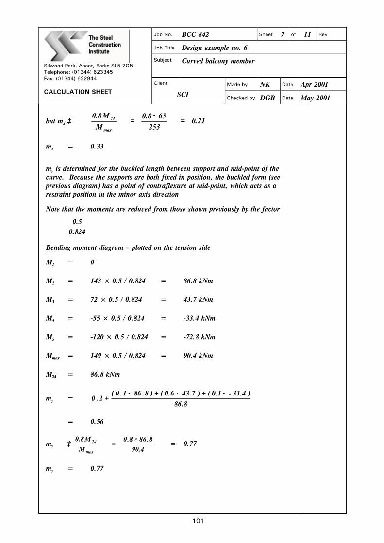
101
Job No. BCC 842 Sheet 7 of 11 Rev
Job Title Design example no. 6
Subject Curved balcony member
Made by NK Date Apr 2001
Silwood Park, Ascot, Berks SL5 7QN Telephone: (01344) 623345 Fax: (01344) 622944 CALCULATION SHEET
Client
SCI Checked by DGB Date May 2001
but mx ≥≥ 21.0253
658.0
M
M8.0
max
24 ==××
==
mx = 0.33
my is determined for the buckled length between support and mid-point of the curve. Because the supports are both fixed in position, the buckled form (see previous diagram) has a point of contraflexure at mid-point, which acts as a restraint position in the minor axis direction
Note that the moments are reduced from those shown previously by the factor
824.05.0
Bending moment diagram – plotted on the tension side
M1 = 0
M2 = 143 × 0.5 / 0.824 = 86.8 kNm
M3 = 72 × 0.5 / 0.824 = 43.7 kNm
M4 = -55 × 0.5 / 0.824 = -33.4 kNm
M5 = -120 × 0.5 / 0.824 = -72.8 kNm
Mmax = 149 × 0.5 / 0.824 = 90.4 kNm
M24 = 86.8 kNm
my = 8.86
)4.331.0()7.436.0()8.861.0(2.0
−−××++××++××++
= 0.56
my ≥≥ 4.90
8.868.0
M
M8.0 ×=
max
24 = 0.77
my = 0.77

rTh SteelCenstructuonInstitute
ISilwood Park, Ascot, Berks SL5 7QN
Job No. BCC 842 Sheet 8 of 11 Rev
Job Title Design example no. 6
Subject Curved balcony member
Telephone: (01344) 623345Fax: (01344) 622944
CALCULATION SHEETClient I Made by NK I Date Apr 2001
SCI Checked by DGB Date May 2001
F mM mM1Then —-+ X V '
PC PYZX
0.33x253x106 0.77x90.4x106= 0+ 3+ 3= 0.72,<1 OK
265x 7990x10 265x386.5x10
The second equation to be satisfied (section 8.8.4) is
+ m7M37. + �M, J)yZy1
The member is not curved in the plane of the web, so Mb is calculated as for astraight member
For Mb, 2LT = UVA.,fji
A. = LE / ry = 7854 / 62.7 = 125
taking uv as 0.9 and fiN = 1 for simplicity,
= 0.9 x 125 x 1 = 112.5
Then Pb = 104 N/mm2
Lateral torsional buckling resistance
Mb is based on the length between restraints, which is taken as the developedlength from support to the effective restraint at the mid-point of the curve
for mLT,
M1 = 253 kNm M2 = 127 kNm
M3 = 34.5 kNm M4 = 39 kNm
M5 = 65 kNm M = 253 kNm
mLT 0.2+ (0.15x127)+(O.5x34.5)+(0.15x23) = 0.36
4.3.6.7
Table 16
Table 18
253
102

The SteelConstructionInstitute
Silwood Park, Ascot, Berks SL5 7QN
Job No. BCC 842 Sheet 9 of 11 Rev
Job Title Design example no. 6
Subject Curved balcony member
Telephone: (01344) 623345Fax: (01344) 622944
CALCULATION SHEETClient Made by
SCI Checked by
NK
DGB
Date
Date
Apr 2001
May 2001
But 0.44, therefore mLT = 0.44
m, as before = 0.77
then + mLTMLT + m,M,1 �Pc, pyzycf
0.44x274.1x106 0.77x90.4x106= 0+ +104 x 7990 x io 265 x 386.5 x i03
Hollow section design
= 0.82,<1 OK
For a comparison, a 300 x 200 x 12.5 rectangular hollow section S355 will bechecked as a replacement for the I section previously designed
The design process for a hollow section curved on plan is quite different from thatfor an I section
The I section in the previous calculation resists the resulting torque primarily bywarping, so the flanges were designed to resist the induced horizontal forces. Inhollow sections, the torsional rigidity means thai warping stresses generally do notneed to be considered. The torsional effects are accounted for by calculating theshear stress due to torsion, adding this to the shear stress due to externally appliedloads, and calculating a reduced design strength, Pyd
In the absence of any externally applied horizontal loads or moments, no minoraxis bending need be considered. The design of hollow sections for theseapplications is therefore much simpler than the design of open sections
Section properties
A = 117 cm2
D = 300 mm
B = 200 mm
zx
1•
C
= 952 cm3
= 8.02 cm
= 1220 cm3
As explained in Section 8.7.2, the shear and torsion must be taken into account bycalculating a reduced design yield stress, p
From the analysis, the maximum shear force, F = 77.6kN
From the analysis, the maximum torque was 37.6 kNm
103
SCI P202

104
Job No. BCC 842 Sheet 10 of 11 Rev
Job Title Design example no. 6
Subject Curved balcony member
Made by NK Date Apr 2001
Silwood Park, Ascot, Berks SL5 7QN Telephone: (01344) 623345 Fax: (01344) 622944 CALCULATION SHEET
Client
SCI Checked by DGB Date May 2001
Shear stress = )BD(/AD
106.77 3
++××
4.2.3
= )200300(/)30010117(
106.772
3
++××××××
= 11.1 N/mm2
torsional stress = 3
66
101220
106.37
C
106.37
××××
==××
= 30.8 N/mm2
then ττ, the sum of shear and torsion stresses = 11.1 + 30.8 = 41.9 N/mm2. Because there is no externally applied horizontal moment, σσ2 = 0, and
(( )) 5.022 3pp ττ−−== yyd Section 8.7.2
= [[ ]] 5.022 )9.41(3355 −− = 347.5 N/mm2
Cross-sectional capacity (see Section 8.7.4)
1M
M
M
M
pA
F
cy
y
cx
x
ydg
c ≤≤++++
but Fc = 0 as there is no externally applied axial force, and My = 0 as there is no externally applied minor axis moment
Mcx is the elastic moment capacity, using the reduced design strength pyd Section 6.3.1
then 0109525.347
108.2650
3
6++
××××
××++ = 0.80, < 1 OK

105
Job No. BCC 842 Sheet 11 of 11 Rev
Job Title Design example no. 6
Subject Curved balcony member
Made by NK Date Apr 2001
Silwood Park, Ascot, Berks SL5 7QN Telephone: (01344) 623345 Fax: (01344) 622944 CALCULATION SHEET
Client
SCI Checked by DGB Date May 2001
Compression face buckling (see Section 8.7.5)
Two equations must be satisfied. Firstly: 1Zp
Mm
Zp
Mm
P
F
yy
yy
xyd
xx
c
c ≤≤++++
In this example, there is no externally applied axial force or minor axis moment so both Fc and My = 0
mx (identical to I section) = 0.33
then 1,27.0109525.347
108.26533.0
Zp
Mm3
6
yd
<=××××
=x
xx OK
The second equation to satisfy:
1Zp
Mm
M
Mm
P
F
yy
yy
b
LTLT
cy
<<++++
For the rectangular hollow section, D / B = 300 / 200 = 1.5 4.3.6.1
then the limiting value of LE / ry = 515 (275 / 355) = 399 Table 15
LE / ry = 7854 / 80.2 = 98, < 399
Therefore, Mb = Mcx
mLT (identical to I section) = 0.44
then 3
6
b
LTLT
109525.347
108.26544.0
M
Mm
××××××××
== = 0.35, <1 OK
It will be appreciated that the chosen hollow section is a conservative choice, based on the ultimate limit state calculations above, because the governing cross-sectional capacity check results in a usage factor of 0.8
However, the contrast of member weights (226 kg/m for the I section and 91.9 kg/m for the hollow section) demonstrates the suitability of closed sections, compared with I sections when members are subject to combined bending and torsion
Designers should note that serviceability limit state checks will often be critical in the design of members curved on plan.
106
10 REFERENCES
1 BRITISH STANDARDS INSTITUTION BS 5950: Structural use of steelwork in building BS 5950–1:2000 Code of practice for design: rolled and welded sections BSI, 2001 2 BRITISH STANDARDS INSTITUTION BS 5500: Specification for unfired fusion welded pressure vessels
(Withdrawn) BSI, 1997
3 PACKER, J.A. and HENDERSON, J.E. Hollow structural sections; Connections and trusses Canadian Institute of Steel Construction, 1997
4 DEUTSCHES INSTITUT FÜR NORMUNG DIN 18 800, Part 2 Structural steelwork – analysis of safety against buckling of linear members and frames (1996 Amendment) DIN, 1996
5 GALAMBOS, T.V. (Editor) Guide to stability design criteria for metal structures, Fifth edition John Wiley & Sons Inc., 1998
6 THE STEEL CONSTRUCTION INSTITUTE AND THE BRITISH CONSTRUCTIONAL STEELWORK ASSOCIATION Steelwork design guide to BS 5950-1:2000 Volume 1: Section properties and member capacities, 6th Edition (SCI P202) The Steel Construction Institute, 2001
7 KING, C.M. In-plane stability of portal frames to BS 5950-1:2000 The Steel Construction Institute, 2001
8 VACHARAJITTIPHAN, P. and TRAHAIR, N.S. Flexural-torsional buckling of curved members ASCE, Journal of the Structural Division, June 1975
9 TIMOSHENKO, S.P. Theory of elastic stability McGraw Hill, 1961
10 BAKER, J. The steel skeleton, Volume 2. Plastic behaviour and design Cambridge University Press, 1965
11 TRAHAIR, N.S. Flexural-torsional buckling of structures E & FN Spon, 1993

SCI-P281 Design of Curved Steel
107
APPENDIX A LATERAL TORSIONAL BUCKLING OF CURVED BEAMS
A.1 General In BS 5950-1:2000 the elastic critical buckling stress, pE, is used to derive the slenderness, λLT, which gives the appropriate value of bending stress, pb.
BS 5950-1 assumes that members are straight in the unstressed condition, so this publication gives formulae from which λLT may be derived for beams that are curved in the plane of the bending moment, as given in Section 6.5.3.
Curved members resisting a bending moment that compresses the convex flange are less stable than straight members, so λLT should be modified by the approach given in Section 6.5.3.
Curved members resisting a bending moment that compresses the concave flange are more stable than straight members in terms of resistance to lateral torsional stability. However, it is recommended that the stability is taken as equal to a straight member unless further studies (and perhaps testing) are conducted into the following effects:
(i) Radial compression in the web
Radial compression is caused in the web because the inner flange in compression reacts radially outwards and the outer flange in tension reacts radially inwards. The published solutions for the elastic critical buckling moment do not appear to consider this compression, which should be expected to reduce the stability of the member. In members with the opposite bending moment, the web carries a radial tension, which will not destabilise the section.
(ii) The buckling stress curve, pb, versus λLT
The form of buckling curves is given in the code by a formula, but this formula is derived principally from test results. The general form is shown in Figure A.1, and is in three parts.
• At low slenderness, pb forms a plateau at py.
• At intermediate slenderness, pb lies below both py and the elastic critical buckling stress pE.
• At high slenderness, pb approaches the elastic critical buckling pE.

SCI-P281 Design of Curved Steel
108
LTλλλ 0
Stress
p y
p E
p b
Figure A.1 Buckling stress curve, pb
In the region of the plateau, the values of pb depend greatly on test results because the elasto-plastic behaviour of real sections including residual stresses is very complex. In the region of the plateau, the flanges become plastic, so lateral bending stiffness reduces towards zero. Therefore, curved beams derive less benefit (in lateral torsional resistance) from the effect of curvature than predicted by elastic critical buckling theory. Whereas tests have demonstrated the buckling resistance of straight members, no such tests exist for curved members. For this reason, it is not advisable to use the effect of curvature to improve the stability without further study of what the relationship of pb and λLT should be for curved members.
A.2 Derivation of ME
A.2.1 General The formula given for ME in Section 6.5.3 can be derived from the work of numerous authors[8,9,10]. Derivations from the equations presented by two of these authors are given in the following sections. Later work by Trahair[11] gives a more generalised solution for curved members. This gives a slightly different solution, but for the range of applications of this document the differences are not significant. The formula derived from the earlier work has been used because it is more generally available in design offices through references such as Flexural-torsional buckling of curved members[8] and Theory of elastic stability[9].

SCI-P281 Design of Curved Steel
A.2. 1 .1 From Vacharajittiphan and Trahair
Equations 27 and 28 of Flexural-torsional buckling of curved members'8 give
(El +'yGJ I(EI +yGJ"2 (2 1M= I 1±11'
I +I————IEIyGJ (27)2R ) 2R ) L2 R2)
'
in which =11 + itEI(28)
( GJL2)
( 2j\ 2E1:.7GJ=I1+ W IGJ=GJ+
I GJL2) L2
The above uses the opposite sense for R positive to that in this document. Inthis document, R positive indicates compression on the outer flange.Section 6.5.3 defines:a = E4
2EH itElb = GJ+" =GJ+
L2 L2
c = a+bME = elastic critical buckling moment.
Writing equation 27 in terms of 6.5.3
1' 2 (2ME = —---± II—--I +I———lab
2R '. 2R) L2 R2)
Retaining only the positive solution (negative ME is meaningless)
c I(c2 (2 1—---+ it — I +41 tab
R 1R) L2 R2)ME = as 6.5.3.2
A.2.2 From Timoshenko and GoreFrom Theory of elastic stability, 2nd edition91, Article 7.10, page 313:
The Timoshenko formula uses C for the torsional stiffness term. C, as defined,does not include the warping stiffness because the member considered is a thinstrip curved in plane. To use it for normal structural sections, the torsionalstiffness must include both the pure torsional stiffness and the warping stiffness.Therefore, C is redefmed as:
C in Timoshenko = b of 6.5.3
EI in Timoshenko = a of 6.5.3
oR in Timoshenko = Lof6.5.3RinTimoshenko = -Rof6.5.3
109

SCI-P281 Design of Curved Steel
110
Equation 7-33[9] gives the positive root of the equation as
Mcr = 22
2x
2xx
22 α
π
R
CEI
R
CEI
R
CEI+
−+
+
Writing in terms of 6.5.3
ME = ++
−Rba
2
π+
−−
2
22
2 Lab
Rba
= 2
42
2
2
2
22
abLR
baba
Rc
π+
+−
+
= 2
442
2
2
22
22
abLR
ab
R
babaRc
π+−
+++
= 2
14
22
22
abRLR
cRc
−
π+
+−
as 6.5.3.

SCI-P281 Design of Curved Steel
111
APPENDIX B SPECIALIST CONTACT DETAILS
The following specialist companies will be pleased to supply information on any aspect of curved steel.
The Angle Ring Company Limited Bloomfield Road Tipton West Midlands DY4 9EH Tel. 0121 557 7241 Fax. 0121 522 4555
www.anglering.co.uk
Barnshaws Steel Bending Group Tipton Road Tividale Oldbury West Midlands B69 3HY Tel. 0121 557 8261 Fax. 0121 557 5323
www.barnshaws.com

SCI-P281 Design of Curved Steel
112
APPENDIX C PHOTOGRAPHIC CREDITS
Front cover (top) National Botanical Gardens of Wales Client: National Botanical Gardens of Wales Engineer: Anthony Hunt Associates Architect: Sir Normal Foster Partnership Front cover (bottom) Visitors Centre, Fountains Abbey Client: The National Trust Engineer: Jampel Davison and Bell
Architect: Edward Cullinan Architects
Figure 2.3 Trafford Centre Client: Peel Holdings Engineer: Bingham Cotterell & Partners Architect: Leach Rhodes and Walker Figure 2.4 Lenzie Academy Sports Hall Client: East Dunbartonshire Council Engineer: Charles Scott & Partners Architect: East Dunbartonshire Council Figure 2.5 Velodrome – National Cycling Arena Client: Manchester City Council Engineer: AMEC Architect: FaulknerBrowns Figure 2.6 Poplar High Level Walkway Client: LDDC/Wetherby Engineer: Maunsell & Partners Architect: Ahrends Burton & Koralek Figure 2.7 The Rotunda, Broadgate Development Client: Rosehaugh Stanhope Developments plc Engineer: Arup Associates Architect: Arup Associates