Embed Size (px)
Citation preview
AC 2007-3083: DESIGN OF DATA ACQUISITION SYSTEM FOR COMPUTERENGINEERING EDUCATION
Yoon Kim, Virginia State UniversityYOON G. KIM is an Assistant Professor of Computer Engineering in the Department ofEngineering and Technology at Virginia State University. He earned his M.S. and D.Sc. degreesin Electrical Engineering from Washington Univ. in St. Louis in 2000 and 2005, respectively. Hejoined the faculty at VSU in 2004. He has over 11 years of industrial experience in the area oftelecommunication systems. His research interests include Internet traffic engineering, wirelesssensor networks, and data acquisition.
Shahzad Akbar, Dr. Shahzad Akbar received his PhD in Electrical Engineering from Cornell University and hisMS from MIT. He has many years of industrial Research and Development experience at IBMMicroelectronics, Sematech, DuPont, Hewlett-Packard and Siemens. Presently, he is a facultymember and coordinator of the Computer Engineering Program in the Engineering Department atVirginia State University.
© American Society for Engineering Education, 2007
Page 12.459.1
Design of Data Acquisition System for Computer Engineering
Education
Abstract
A microcontroller based data acquisition system presented is designed for computer engineering
students to enhance their knowledge of both microcontrollers and analog circuits, such as A/DC
(analog-to-digital conversion), D/AC and integrated-circuit temperature sensors. The system also
provides students real-world examples of microcontrollers application and helps students
understand how a microcontroller, C language programming, and analog circuits work together
to become an embedded system. In addition, it provides a tool for the students to program
hardware specific driver codes and to test the system to meet design requirements. The design
involves integration of an 8051-based microcontroller, a 12-bit serial A/D converter, an 8-bit
D/A converter, an instrumentation operational amplifier, a keypad, and a liquid crystal display.
Once the C-language code is compiled, students can download the machine-language code to the
system using a PC serial port and do not need any external EPROM burner. The data acquisition
system has non-volatile flash memory to hold the code, which allows students to run their code
in a stand-alone mode.
Introduction
Computer engineering is a discipline that combines both computer science and electrical
engineering and prepares students for careers that deal with software and hardware components
of modern computer systems 1. To educate computer engineering students effectively and
practically one needs to provide hands-on activity in class. It would be beneficial if they were
exposed to real-world engineering problems, which involve both software and hardware
components of computer systems. Utilizing a computer platform to build an embedded system
could provide hands-on and practical examples for students 2. In this paper, we employ a
microcontroller based data acquisition system as the platform.
Data acquisition involves sampling of signals and processing the signals to generate useful
information. These are usually achieved by microprocessor/microcontroller related hardware and
software. Courses in microprocessors and microcontrollers are standard parts of computer
engineering curriculum in general. Computer Engineering at Virginia State University (VSU)
offers computer system related courses such as CPEG 307 (Linear System Analysis) that covers
subjects on sampling and discrete-time signals, ENGR 204 (Object-Oriented Programming),
CPEG 303 (Intro. to Electronics), CPEG 208 (Microprocessors), CPEG 416 (Adv.
Microcontrollers), and CPEG 404 (Data Acquisition and Control System).
The design of data acquisition system allows computer engineering students to weave together
the knowledge gained from these courses in the curriculum. The system also provides students
real-world examples of microcontrollers applications and helps students understand how a
microcontroller, C language programming, and analog circuits all work together to become an
embedded system. In addition, it provides a tool for the students to program hardware specific
driver codes and to test the system to meet design requirements.
Page 12.459.2

Hardware Platform
The block diagram of the data acquisition system is shown in Figure 1. The D/A conversion
circuits are used to generate arbitrary waveforms such as a saw tooth waveform, a pulse, and a
PWM waveform. Each waveform is generated by a C language program running on the
microcontroller board. The voltage regulators are required to supply +5 and –5 Volts to the
analog circuits in both conversion circuits. The serial A/D converter is used to save the number
of input/output (I/O) pins of the microcontroller. The notation Px.y in Figure 1 implies x port and
y pin of the microcontroller I/O. The microcontroller board, keypad, and LCD module are off-
the-shelf products. The microcontroller in the board is DS89C420 7 that is compatible with Intel
8051.
D/A Conversion
Circuits
Analog
Output +5/-5 Voltage
Regulators for
Analog Circuits
9V
DC
120V
AC
9V
DC
A/D Conversion
Circuits
Analog
Input
Microcontroller
Board (MDE8051)
Keypad
4 x 4 Matrix LCD Module
20 x 2 Characters
3
+5, 0, -5 V
3P3.7~P3.5
8P2.7~P2.0
P0.7~P0.0
8
3
P3.4, P3.2, P1.7
P3.3
9V
DC
(Temp.
Sensor)
(Arbt.
Wave)
Figure 1. Block Diagram of Data Acquisition System
The platform includes the following blocks and associated components in each block.
• Digital-to-Analog Conversion
o 8-bit D/A Converter DAC0800 3
o TTL Buffer 74LS244
Page 12.459.3
• Voltage Regulator for Analog Circuits
o +5 Volt Regulator 7805
o -5 Volt Regulator 7905
o Filter Capacitors and LEDs
• Analog-to-Digital Conversion
o 12-bit Serial A/D Converter MCP3202 4
o Instrumentation Operational Amplifier OP07 5
• Microcontroller Board MDE8051 6
o Intel 8051 Compatible Microcontroller DS89C420 7
o 16KB Flash Memory
o 256 Byte RAM
o In-System Programmable through RS-232 Serial Port
o Two RS-232 Serial Ports
• LCD Module 08LCD11 8
o 20 x 2 LCD Character Module
• Keypad 17KP1604 9
o 4 x 4 Matrix
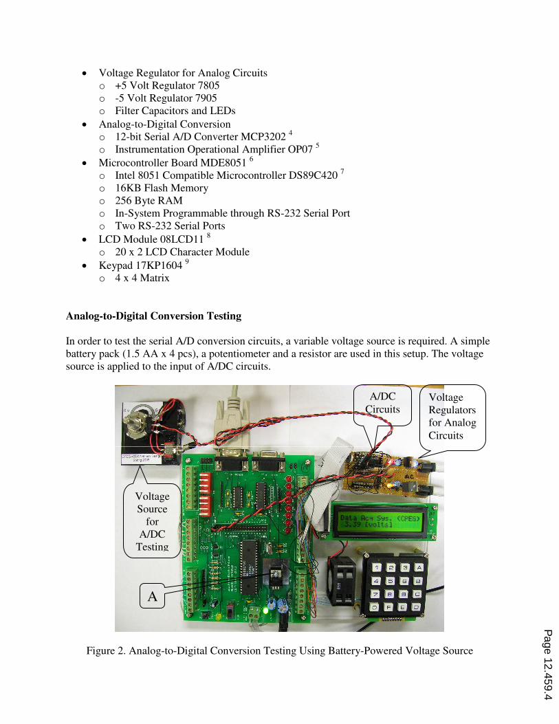
Analog-to-Digital Conversion Testing
In order to test the serial A/D conversion circuits, a variable voltage source is required. A simple
battery pack (1.5 AA x 4 pcs), a potentiometer and a resistor are used in this setup. The voltage
source is applied to the input of A/DC circuits.
Figure 2. Analog-to-Digital Conversion Testing Using Battery-Powered Voltage Source
A
Voltage
Source
for
A/DC
Testing
A/DC
Circuits Voltage
Regulators
for Analog
Circuits
Page 12.459.4
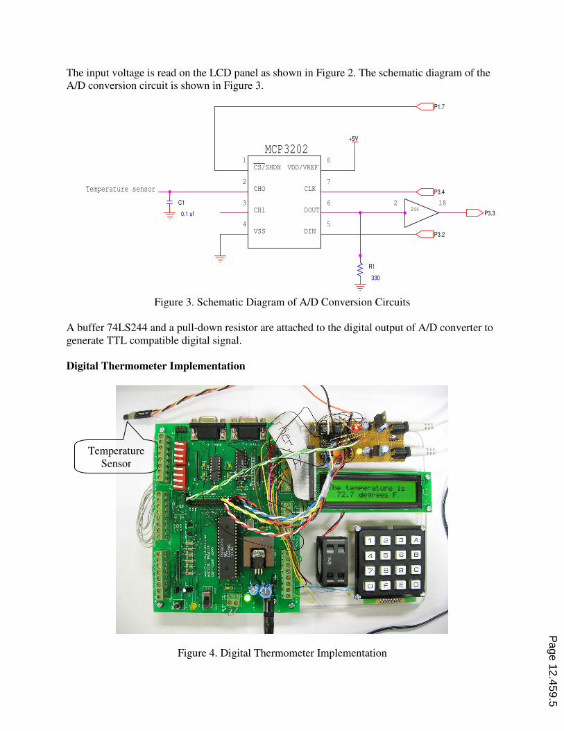
The input voltage is read on the LCD panel as shown in Figure 2. The schematic diagram of the
A/D conversion circuit is shown in Figure 3.
Figure 3. Schematic Diagram of A/D Conversion Circuits
A buffer 74LS244 and a pull-down resistor are attached to the digital output of A/D converter to
generate TTL compatible digital signal.
Digital Thermometer Implementation
Figure 4. Digital Thermometer Implementation
3
4
C1
0.1 uf
5
6244
CLK7
8
P3.2
DOUT
Temperature sensor
18
+5V
DIN
CS/SHDN
MCP3202
P3.4CHO
P1.7
CH1
VSS
P3.3
1
2
R1
330
2
VDD/VREF
Temperature
Sensor
Page 12.459.5
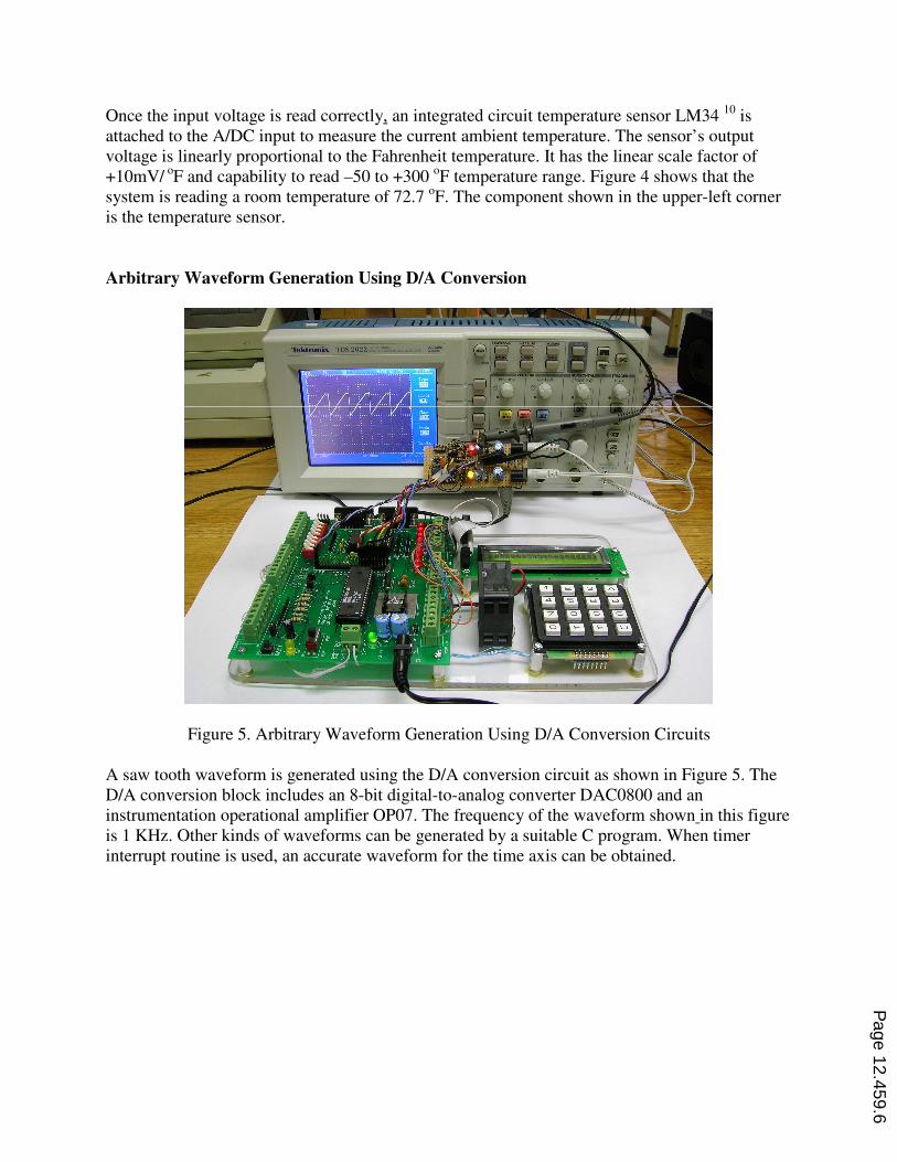
Once the input voltage is read correctly, an integrated circuit temperature sensor LM34 10
is
attached to the A/DC input to measure the current ambient temperature. The sensor’s output
voltage is linearly proportional to the Fahrenheit temperature. It has the linear scale factor of
+10mV/ oF and capability to read –50 to +300
oF temperature range. Figure 4 shows that the
system is reading a room temperature of 72.7 oF. The component shown in the upper-left corner
is the temperature sensor.
Arbitrary Waveform Generation Using D/A Conversion
Figure 5. Arbitrary Waveform Generation Using D/A Conversion Circuits
A saw tooth waveform is generated using the D/A conversion circuit as shown in Figure 5. The
D/A conversion block includes an 8-bit digital-to-analog converter DAC0800 and an
instrumentation operational amplifier OP07. The frequency of the waveform shown in this figure
is 1 KHz. Other kinds of waveforms can be generated by a suitable C program. When timer
interrupt routine is used, an accurate waveform for the time axis can be obtained.
Page 12.459.6
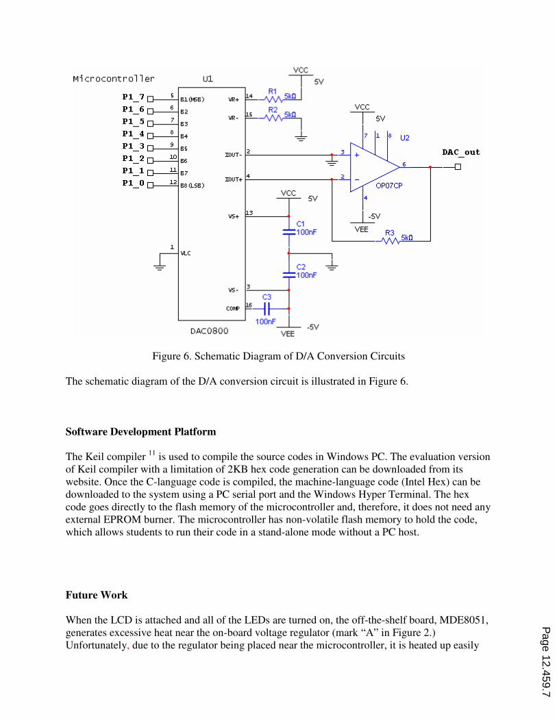
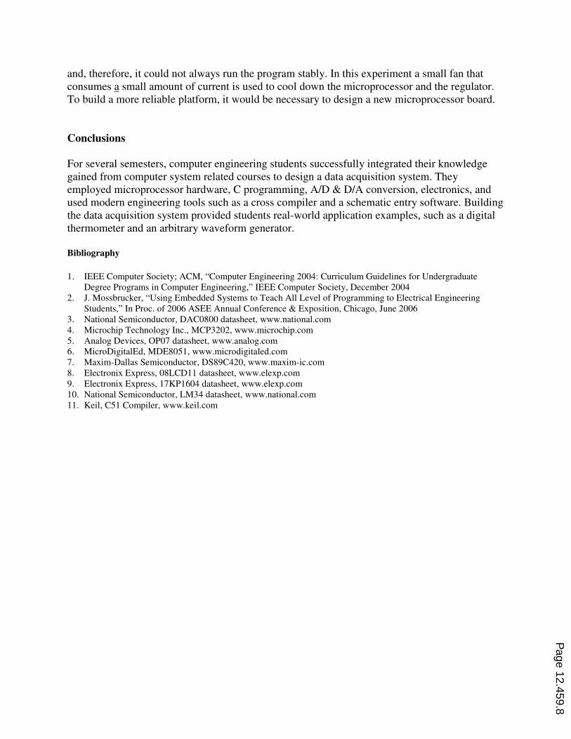
Figure 6. Schematic Diagram of D/A Conversion Circuits
The schematic diagram of the D/A conversion circuit is illustrated in Figure 6.
Software Development Platform
The Keil compiler 11
is used to compile the source codes in Windows PC. The evaluation version
of Keil compiler with a limitation of 2KB hex code generation can be downloaded from its
website. Once the C-language code is compiled, the machine-language code (Intel Hex) can be
downloaded to the system using a PC serial port and the Windows Hyper Terminal. The hex
code goes directly to the flash memory of the microcontroller and, therefore, it does not need any
external EPROM burner. The microcontroller has non-volatile flash memory to hold the code,
which allows students to run their code in a stand-alone mode without a PC host.
Future Work
When the LCD is attached and all of the LEDs are turned on, the off-the-shelf board, MDE8051,
generates excessive heat near the on-board voltage regulator (mark “A” in Figure 2.)
Unfortunately, due to the regulator being placed near the microcontroller, it is heated up easily
Page 12.459.7
and, therefore, it could not always run the program stably. In this experiment a small fan that
consumes a small amount of current is used to cool down the microprocessor and the regulator.
To build a more reliable platform, it would be necessary to design a new microprocessor board.
Conclusions
For several semesters, computer engineering students successfully integrated their knowledge
gained from computer system related courses to design a data acquisition system. They
employed microprocessor hardware, C programming, A/D & D/A conversion, electronics, and
used modern engineering tools such as a cross compiler and a schematic entry software. Building
the data acquisition system provided students real-world application examples, such as a digital
thermometer and an arbitrary waveform generator.
Bibliography
1. IEEE Computer Society; ACM, “Computer Engineering 2004: Curriculum Guidelines for Undergraduate
Degree Programs in Computer Engineering,” IEEE Computer Society, December 2004
2. J. Mossbrucker, “Using Embedded Systems to Teach All Level of Programming to Electrical Engineering
Students,” In Proc. of 2006 ASEE Annual Conference & Exposition, Chicago, June 2006
3. National Semiconductor, DAC0800 datasheet, www.national.com
4. Microchip Technology Inc., MCP3202, www.microchip.com
5. Analog Devices, OP07 datasheet, www.analog.com
6. MicroDigitalEd, MDE8051, www.microdigitaled.com
7. Maxim-Dallas Semiconductor, DS89C420, www.maxim-ic.com
8. Electronix Express, 08LCD11 datasheet, www.elexp.com
9. Electronix Express, 17KP1604 datasheet, www.elexp.com
10. National Semiconductor, LM34 datasheet, www.national.com
11. Keil, C51 Compiler, www.keil.com
Page 12.459.8